1
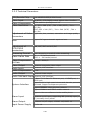
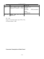
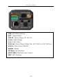
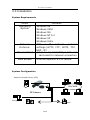
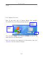
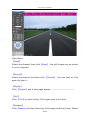
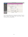
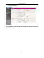
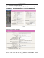
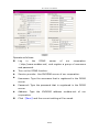
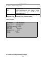
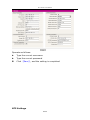
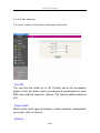
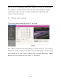
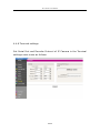
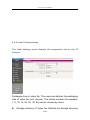
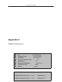
IP Camera User Manual VNS IP Camera User Manual English Version VNS IP Camera User Manual Thank you for using the IP Camera of our corporation! IP Camera User Manual Intended Use The IP Camera is a high-performance web-ready camera. Also it can be part of a flexible surveillance system. This manual explains how to operate the IP Camera. As this section gives tip on User Manual, read it before you operate the camera. If you have any problems please contact our technical support or the dealer. The IP Camera is a network device and its user should be straight forwards to those who have basic network knowledge. It is important to check and ensure that all the contents received are complete according to the list in the Package Contents chapters. Read carefully and follow the instructions in Installation chapter to avoid damages due to faulty assembly and installation. The Operating the Camera chapter suggests the best way to utilize IP Camera and ensure proper operation. The IP Camera refers to network camera; Click means left click; Double click means double left click. Attention: Our corporation reserves the right to make any modification to this manual or the information contained herein at any time without notice. IP Camera User Manual Table of Contents Intended Use......................................................................3 Overview............................................................................5 2.1 Package Contents.........................................................5 2.3 Features...................................................................................8 Installation...................................................................................11 3.3 Installation.............................................................................18 Operating the Camera.......................................................20 4.1 Check Connection...................................................................20 4.3 Visit IP Camera via Internet Explorer.....................................23 4.4 IP Camera Parameter Settings ...............................................27 4.4.1 System settings..................................................................................................... 29 4.4.3 User Manage settings........................................................................................... 37 4.4.4 Audio settings....................................................................................................... 38 4.4.5 Video settings....................................................................................................... 39 4.4.6 Motion alarm settings........................................................................................... 40 4.4.7 Sensor alarm settings............................................................................................ 42 4.4.8 Terminal settings.................................................................................................. 43 IP Camera User Manual Overview 2.1 Package Contents i ii iii iv v vi IP Camera DC 12V Power Adapter User Manual CD Certification & Reparation Warranty Reparation Warranty 1 1 1 1 1 1 Caution: Please check your package according to the list. If you find any damaged or missed items, please contact your dealer. This apparatus shall not be exposed to dripping or splashing and no objects filled with liquid, such as vases, shall be placed on the apparatus. 2.2 Technical Description 5/ 50 IP Camera User Manual 2.2.1 Introduction Responding to the growing demand for an affordable and easy-touse network camera, the IP Camera is introduced. The IP Camera offers a cost-effective network solution for a broad range of remote monitoring applications, such as small and mid-sized business office, retail as well as web casting. Thanks to the latest technique of High-density and programmable communication media processor SOC Hi3510 single chip solution (equipped with ARM9 and DSP high integration two processors), with the powerful RTOS (Real-time Operating System) the IP Camera can achieve the high performance and low cost digital multimedia process combining audio & video collection, compression and network transmission. It allows users to carry out remote monitoring and security surveillance over LAN and WAN. The IP Camera incorporates a variety of convenient features. The high frame-rate transmission of Optimized H.264 video compression algorithm supports the smooth viewing of high quality images. Within embed web server, images can be viewed and managed from a PC running a standard web browser. What’s more the central management software realizes integrated surveillance and management of multiple network cameras. It is ideally suitable for building a large video surveillance system over LAN and WAN. 6/ 50 IP Camera User Manual 2.2.2 Technical Parameters CPU/Encode Chip 32bit ARM926+DSP/H.264 Encode Video Input Video Compression PAL/NTSC; CCD/CMOS module digital video interface Video Resolution PAL: 352 x 288(CIF), 704 x 288(2CIF), 704 x 576(D1) NTSC: 352 x 240(CIF), 704 x 240(2CIF), 704 x 480(D1) H.264 baseline profile@Level 2.2 Adjustment of Video Brightness, hue, contrast, saturation and image quality Parameters Lens Support DC type automatic aperture lens. Adjustment of CCD/CMOS parameters Streaming Format AWB, AGC, BLC and ALC/ELC Video Frame Rate PAL: 1 - 25 frames/second NTSC: 1 - 30 frames/second Video Compression Bit Rate 16Kbit/S~8Mbit/S Video Output Audio Input 1 channel composite video output Audio Compression Audio Output G.726 Video streaming or audio & video streaming 1 channel, MIC interface 1 channel linear output Audio Talk-back Input 1 channel, MIC interface 10 Base-T/100 Base-TX Ethernet port, 1 RS485 port, 1 RS232 port System Interface Support built-in high-speed domes and decoder protocols download. Support transparent protocols. Support IEEE802.11b/g wireless network Support CDMA1X and GPRS mobile network Support video surveillance via the mobile phone. Alarm Input 1 channel on/off input, supporting NO (normally open) or NC (normally close) sense. Alarm Output 1 channel on/off output, 120VAC 1A/24VDC 1A Input Power Supply DC 12V 1A 7/ 50 IP Camera User Manual Maximum Power Less than 5W Operating Temperature -10 ~ +55 ℃ Operating Humidity 10 ~ 85% Storage Temperature -20 ~ +70 ℃ System Requirements Operating System: Microsoft Windows 98/ME/2000/XP/2003 Brower: Microsoft Internet Explorer 5.0 or above. Others: The PC graphics card used for installation is required to support conversion and zoom in & out of image color. The tested VGA are as follows: Nvidia Tnt/Tnt2, Geforce Mx200/400/420/440, Fx5200/5600 and its series. ATIR adeon 7000/7200/7500/8500/9000/9200/9500/9600 and its series, MatroxG450/550, INTEL845G/865G and its series 。 Please attend that the driving of graphics card must support hard wall zoom in & out function. 2.3 Features The IP Camera is a network camera equipped with a built-in Web server. The camera has the following features. High Quality Image With the high-functional programmable communication media processor Hi3510, SOC single chip solution, built-in (ARM +DSP), and high-speed video protocol 8/ 50 processor, the IP Camera IP Camera User Manual incorporates CCD or other CMOS sensors offers super high quality image with excellent sensitivity. The IP camera also supports image masking/image capturing. Selectable Image Quality and Size The IP Camera provides the flexibility to select image quality and image size according to network bandwidth. Image size can be selected from two modes: PAL (CIF 352 x 288, 2CIF 704 x 288, D1 704 x 576); NTSC (CIF 352 x 240, 2CIF 704 x 240, D1 704 x 480). What’s more the IP Camera supports variable bit rate from 16Kbps to 2Mbps (with a variable up to maximum 30 fps frame rate), providing high quality image. Image/Video Storage With its CF card or USB storage, the IP Camera can save image or video. High Frame Rate The IP Camera produces images with a maximum frame rate of 30 fps, allowing for clear and smooth frame-accurate images to be viewed. The frame rate can be fixed or set to a variable rate that automatically adjusts to the available bandwidth. Remote Monitoring/Control Over Networks The IP Camera is equipped with a 10Base-T/100Base-TX interface and a built-in web server. This allows PC running a standard web browser to monitor live imagines and control the camera without the need of additional software. Up to 10 simultaneous users can access and monitor the images of a single IP Camera. With the single chip solution, and H.264 baseline profile@Level 2.2, the IP Camera realizes the transmission of high definition video over low network bandwidth. 9/ 50 IP Camera User Manual The IP camera is ideally suitable for surveillance, remote monitoring and versatile web-casting applications. It supports dynamic IP address, LAN and Internet (ADSL & Cable Modem). Furthermore it supports WiFi/802.11b/g wireless network, CDMA1X and GPRS mobile network and surveillance via mobile phone. Multilateral Network Protocols and Transparent Protocols The IP Camera supports HTTP, TCP/IP, UDP, SMTP, PPPOE, DDNS, DNS, SNTP, BOOTP, DHCP, FTP, and SNMP Network protocols. With RS485 / RS232 serial port companied with several built-in highspeed domes and decoder protocols, it supports transparent protocols. Alarm Function The IP camera provides video lost 、 motion detection and sensor alarm functions (Area & Sensitivity can be set). The IP camera is equipped with a built-in motion detection function that can generate an alarm through alarm-output port. Unlike conventional activity detection, the IP camera provides video lost. Audio Monitoring Incorporation with the built microphone and external microphone input, the IP Camera allows users to monitor audio in addition to video images. The line out-put jack allows connection of a commercially available speaker system with built in amplifier so that the sound transmitted via the network can be out put from the connected speaker system. Auto-recovery and Auto-connection Functions The IP Camera has auto recovery function when exception occurs. It can auto-connect with Internet when the network is interrupted. 10/ 50 IP Camera User Manual Furthermore the system supports remote-system-upgrade. Installation 3.1 Physical Description Mass Dimension (W×H×D) Power requirement Power consumption Operating temperature Storaging temperature 0.8 kg 74mm×40mm×158mm 12 V < 5W -10 ~ +55 ℃ -22 ~ +70 ℃ 11/ 50 IP Camera User Manual Operating humidity Operating system Processor 10 ~ 85% Microsoft Windows 98/ME/2000/XP/2003 SOC single chip solution (ARM9&DSP) 3.2 System Structure Connector description of Main Board 12/ 50 IP Camera User Manual * The pins denoted by “ 口 ” (J1-J9) in the figure are listed as follows: Pin J1 Function I/O pin interface,10 core 13/ 50 Core Function 1:RS485- IP Camera User Manual 2:RS485+ 3:LINE OUT ( Audio Output ) 4:ALARM IN 5:ALARM OUT A 6:ALARM OUT B 7:GND 8:RS232 RXD 9:RS232 TXD 10:NC J2 J3 J4 Auto aperture interface,4 core DC12V power interface,2 core pin pin Ethernet pin interface , 8 core Re. Auto aperture interface connect tech. 1:+12V 2:GND 1:TX+ 2:TX3:RX+ 4.5:with 75R 6:RX7.8:with 75R J5 Decoder Video output,2 core pin 1:VIDEO OUT 2:VIDEO GND (simulation video) J6 Audio output & input pin interface,4 core 1:LINE IN 2.3 : AUDIO GND(simulation audio ) 4:LINE OUT J7 Microphone input interface,2 core pin J8 CCD signal pin interface,5 core 1:MICROPHONE 2:AUDIO GND(simulation audio) 1:BLC 2:AGC 3:AI/EE 4:AWB 14/ 50 IP Camera User Manual 5:IRIS IN J9 CCD power and video signal pin interface,4 core 1:+12V/0.5A 2:GND 3:VIDIO video) 4:VIDEO IN JX2 JX3 match with HH9000-M JX2 JX3 of DC: 12V; Power of encoder board (non CCD): 3W; CCD and others: 10W. Connector Description of Back Panel 15/ 50 GND(simulation IP Camera User Manual Connector Description: LAN: RJ45 Ethernet Port RST: Reset Button DC12V: Power Supply, DC 12V/1A AUTO IRIS: Electrical Len’s control port, support DC Lens MIC: External Microphone connector I/O: as show in figure 4 I/O \ A-OUT: Audio Out 485A: RS485A 485B: RS485B ALM-IN: Alarm In (NO/NC) GND: Ground 232T: RS232TXD 232R: RS232RXD ALM-OA: Alarm Out-A (Relay Out, AC 120V/1A or DC 24V/1A) ALM-OB: Alarm Out-B (Relay Out, AC 120V/1A or DC 24V/1A) *WiFi&SD Model Back Panel 16/ 50 IP Camera User Manual LAN: RJ45 Ethernet Port RST: Reset Button DC12V: Power Supply, DC 12V/1A A out: Audio Output A in: Audio Input ALM out: Alarm Output (Relay Out, AC 120V/1A or DC 24V/1A) ALM in: Alarm Input (NO/NC) RS485: RS485 SD Card: SD Card Slot AUTO IRIS: Electrical Len’s Control ANT: WiFi Antenna 17/ 50 IP Camera User Manual 3.3 Installation System Requirements Items Operating System Network Protocols Ethernet Card WEB Brower contents Windows 98 Windows 2000 Windows ME Windows NT 5.0 Windows XP Windows Vista TCP / IP network protocol settings(HTTP,FTP,SMTP,TCP, UDP,IP) Adapt to all 10/100Mbps Ethernet card used for network connection Internet Explorer 6.0 or above. System Configuration Passive Infrared Sensor (PIR) LAN/WAN IP Camera Microphone Alarm Output Speaker 18/ 50 IP Camera User Manual Hardware Installation 1. Connect the IP Camera to the available Network or to your Personal Computer directly. 2. Install the IP Camera and make sure all cables are correctly and firmly connected. 3. Turn power on (DC 12V). 4. The Network Connection Light turns orange within 5 seconds under the normal situation after power on. It indicates that you have finished the physical connection of IP Camera successfully. 19/ 50 IP Camera User Manual Operating the Camera 4.1 Check Connection 1. The leave-factory settings of the IP Camera are as follows. IP: 192.168.1.1. Subnet mask: 255.255.255.0 Please change the IP Address of your computer. The network segment of your computer should be same as that of the IP Camera. For example: 192.168.1.69. and the subnet mask also same. 2. Press 【Start】→【Run】→【Command】to open window, then type ping 192.168.1.1. If the screen lists as follows. That means the IP Camera works normally and connects to network correctly. If the screen displays other information, please confirm the IP address settings of your personal computer are correct and check the network cables. Then use SearchNVS software to search and modify network parameters (such as IP address, subnet mask, gateway and so on). If the ping fails, check the settings and network cables. 20/ 50 IP Camera User Manual 4.2 Modify Network Parameters Instruction: Use SearchNVS software to search and modify network parameters (Such as IP address, subnet mask, gateway and so on). The SearchNVS running path is as following: 1. Find the Search NVS in 【tool software】 directory from the CD and copy it to PC. 2. Install the Central Management software, then follow below path to find SearchNVS: 【Start】---【all programs】--- 【NVS Center500】---【Search NVS】. Note:Run the SearchNVS software to search and modify IP Camera network parameters following the multicast protocol. The firewall forbids the multicast data packet. Please close the firewall first. 3. Click 【Search】button to run SearchNVS software as follow: 【 Local IP 】 connects the IP camera. If your PC is NIC or multiaddressed local IP, please select an IP address to access IP Camera. After searching you can get the following information: Device name, Device model, Channel num, IP address, Subnet mask, Gateway, Data port, Web port, Multicast IP, Multicast port, DNS and MAC. 4. Select the device to be modified, and then click 【 Parameter Setting】, the Network Setting Menu appears. 21/ 50 IP Camera User Manual Modify the network settings and click 【Save】, then the IP Camera will restart. 22/ 50 IP Camera User Manual 4.3 Visit IP Camera via Internet Explorer 4.3.1 Install ActiveX Control You need to install ActiveX Control when you visit IP Camera for the first time. You can install ActiveX Control in two ways: (1) Auto-Installation You need to lower the security level of the IE temporarily in order to install ActiveX Control into your PC as follows: Choose Internet Option: 【tools】→【Internet Option】. Click the label of 【Security】 and your current security setting is displayed. Set the security level low and click 【apply】. Enter your IP Camera address in the IE address line (for example: 192.168.55.234). If you see a dialogue as follows 【Do you want to install ActiveX Control】 Please click 【Yes】 and install ActiveX Control. Once finished installing your ActiveX Control, retrieve your security setup for default value. (2) Download Installation Download ActiveX Control compressed package from the IP Camera and decompress it to a temporary directory. Double-click the file named 【install. bat】 in the compressed directory at the end. 23/ 50 IP Camera User Manual Download Installation as follows: Download ActiveX When you finish the installation, the system will give you a hint that you have installed successfully. *ATTENTION When download ActiveX Control all other web pages must be 24/ 50 IP Camera User Manual closed. 4.3.2 Logging in as a user Open IE and enter your IP Camera address (For example: 192.168.55.160), the following dialogue appears: Download ActiveX Control Download ActiveX Control Data port (The username Admin and Password 123456 are set at the leave-factory for the Administrator.) Enter the username and password for Administrator, then click 【submit】, the main viewer will appear: 25/ 50 IP Camera User Manual Main Menu: 【Snap】 Select the channel then click【Snap】, the still image can be stored in your computer. 【Record】 Select the channel first then click 【Record】. You can start or click again to stop it. 【Replay】 Click 【Replay】and a play page appear. ------------------------【Call】 Click 【Call】to start calling. Click again and it will stop. 【Speaker】 Click【Speaker】to start listening. Click again and it will stop. Select 26/ 50 IP Camera User Manual different channel will result in different listen channel. 4.4 IP Camera Parameter Settings This section explains how to setup the IP Camera. Only when you are the Administrator of this system can you enter the parameter settings main viewer. Click 【Setup】the Main Viewer is as follow: 27/ 50 IP Camera User Manual The IP Camera setting menu is composed of nine tabs. Those are System, Network, User Manage, Audio, Video, Motion, Sensor, Terminal and Local Config Settings. 28/ 50 IP Camera User Manual 4.4.1 System settings You can set up time, device name, language, standard, encoding format and so on, 29/ 50 IP Camera User Manual Main Menu: 【upgrade】 Click 【browse】 and then select the correct file for upgrading. (Type must be correct). Click 【upgrade 】 to begin upgrade. After finish this, the IP camera will reboot automatically. Only the upgrade file special to this camera can be used. Otherwise problems will occur. Do not shut off the power supply or network until the upgrade completed. 【Restore default】 Resume all the IP Camera parameters (Including Network parameter except MAC address) to default factory settings. Be careful when use this function. 【Reboot】 Click 【Reboot】, the IP Camera will restart after 5 seconds. 30/ 50 IP Camera User Manual 4.4.2 Network Parameter Settings This main viewer is for setting the Basic Parameters, Connect Parameters, DDNS Parameters and PPPOE Parameters. Basic Parameters Settings In this menu, you can set up IP address, subnet mask, default 31/ 50 IP Camera User Manual gateway, MAC address, UDP port, TCP Data Transmission Port, Multicast Address, Multicast Port Number, and DNS address. If the IP camera is applied in LAN, do not set up the IP address same as computer address in LAN. Main Menu 【HTTP Port No.】 The modification of HTTP Port number can change the browser port provided by Web Server in IP camera. 【MAC】 MAC address is the physical address in IP camera. Do not modify it unless special necessity. 【DNS Address】 When DDNS server address or central address is the domain name, Please type the DNS address correctly. 【Connect parameters】 When IP Camera is active connect mode or front-end alarm capture. Please set central URL and port number correctly. 【Send out Parameters】 Low bandwidth data transmission mode can be selected and fit to wireless or low bandwidth network. IP camera DDNS Parameter Settings 32/ 50 IP Camera User Manual Operate as follows: Log in the DDNS server of our corporation (http://www.mvddns.net)and register a group of username and password. Turn on the DDNS function. Service provider: Use MVDDNS server of our corporation. Username: Type the username that is registered in the DDNS server. Password: Type the password that is registered in the DDNS server. Address: Type the MVDDNS address mvddns.net of our corporation. Click 【Save】and the current setting will be saved. 33/ 50 IP Camera User Manual IP camera default network port: TCP UDP Multicast Port 80(Web Port) 5000(Communication port. Audio & Video data transmission port. Talk-Back data transmission port) 5000 (Audio & Video data transmission port) Multicast Port +channel number Factory Default: IP Address: 192.168.55.200 Subnet Mask: 255.255.255. 0 Gateway: 192.168.55.1 Communication Port: 5000 Web port: 80 Multicast: 224.55.8.1 Multicast Port: 5000 DHCP: Close DDNS: Close IP Camera PPPOE parameter settings 34/ 50 IP Camera User Manual Operate as follows: Type the correct username Type the correct password Click 【Save】, and the setting is completed. NTP Settings 35/ 50 IP Camera User Manual Please enter the correct NTP server address and select the correct time zone. 36/ 50 IP Camera User Manual 4.4.3 User Manage settings The User Manage settings main viewer is as follow: You can setup three users for one IP Camera. The Administrator can set parameters for the IP Camera. However, other two general users (user1 and user2) can not. Default Administrator Name: Admin password: 123456 Default General User1’s Name: user1 password: 1 Default General User2’s Name: user2 password: 2 37/ 50 IP Camera User Manual 4.4.4 Audio settings The main viewer of the audio settings is as follow. 【on/off】 You can turn the audio on or off. If audio use is not necessary, please close the audio input, encoding and transmission to save DSP and network resource. (Notes: The factory default status is off.) 【Input type】 Select audio input type according to audio interface configuration you setup. (Mic or Line In) 【Save】 38/ 50 IP Camera User Manual Click 【Save】to save the current settings. 4.4.5 Video settings Set the video parameters of every channel: Title, Bit rate, I frame interval, frame rate, quality of the images (grade 1~30: grade 1 means the highest quality picture, and the bit rate is the biggest; grade 30 means the lowest quality picture and its bit rate is the smallest). Set the mask area: select mask area, you can set or cancel image mask of the current block. Adjust the image parameters: Brightness, chroma, contrast, and saturation. Click 【Save】to save the current settings. While adopting CBR, bit rate and quantity coefficient should be regulated at the same time, if bit rate is very low, coefficient should be strengthened correspondingly in quantity. For instance: (25 frames) when bit rate is set as under 384K, coefficient can be 39/ 50 IP Camera User Manual set as 7 or 8 in quantity. When the network is lower in bandwidth, for improve, transmit frame rate can with appropriate to reduce code frame rate, you can increase coefficient of quantity and reduce I frame interval. 4.4.6 Motion alarm settings The motion alarm settings menu is as follow Set video motion alarm parameters for each channel. The motive detective area (image) is divided into 22*18 blocks. Double-click one block to be set. Set or cancel the motive detection, alarm detective time, switch of the alarm, or sensitive. 40/ 50 IP Camera User Manual Main Menu: 【Area set】 Left click and drag the mouse to fix on the detection area. 【Clear】 Clear the detection area that you setup. 【All】 Setup the whole video areas as detection area. 【Time】 Setup the time quantum of motion alarm detection, such as everyday, or any period of time from Monday to Sunday. 【Detect On】 Turn this function on to get ready for motion alarm. 【Alarm Output】 When any motion is detected the alarm will be output. 【Alarm Delay】 Clear the alarm output time automatically after motion alarmed. 【Alarm Record】 Camera begins to record any motion detected. 41/ 50 IP Camera User Manual 【Save】 Validate the current settings. 4.4.7 Sensor alarm settings The main viewer of Sensor Alarm settings is as follow. You can setup alarm detection parameters for each sensor, including alarm detection time, alarm detection tap, sensor type, alarm delay and alarm output. After setting, click【Save】to validate the current settings. . 42/ 50 IP Camera User Manual 4.4.8 Terminal settings Set Serial Port and Decoder Protocol of IP Camera in the Terminal settings main menu as follows. 43/ 50 IP Camera User Manual 4.4.9 Local Config settings The Local settings menu displays the parameters set on the IP Camera. Packaging time of video file: The users can definite the packaging time of video file (unit: minute). The choice number (for example: 1, 5, 10, 15, 20, 25, 30, 60) can be chosen by users. Storage directory of Video file: Definite the storage directory 44/ 50 IP Camera User Manual of video file. The default path is C:\NDNVS. Storage Contents of snatching Photo: Definite the storage directory of snatching photo. The default path is C:\XDView. Decoder parameter settings: There are two preview modes (real-time priority or flowing priority) can be chosen. Click 【Save】button to save the settings. Appendix 1 FAQ Q: What shall I do if I forget my password? A: The only way to regain access to Vide Server is to utilize the default setting button on the back panel to restore the factory settings and reinstall it. Do not press the RESET button if you are laypeople. All parameters except network physical address will be restored to default parameters after Reset. Q: What shall I do if IP Camera can’t reset after it is upgraded abnormally? A: Firstly, press the RESET on the IP Camera back panel, plug in the IP Camera and unloose the RESET. After 12 seconds, the system will run backup programs. (The backup programs include upgrading and parameter settings. The functions of video & audio are not available). After re-upgrade the system programs, IP Camera will reset normally. Q: Why the ActiveX Control can not be found from IE Explorer? A: It is most probably that your PC has no ActiveX Control. You need to install the ActiveX Control. There are two ways: 45/ 50 IP Camera User Manual (1) Auto-Installation (2) Download Installation The details are described in the manual. Q: Why can not I access IP Camera through IE web browser? A: There are many possible scenarios regarding this problem. 1. If it is an error of network connection, do the following steps: Connect PC to network to test whether they work normally or not. 2. If it is the trouble from IP address, do the following steps: Cut off the connection of IP Camera and network, connect IP Camera and PC, then set IP address again according to recommendatory operation. 3. If IP address lies in different subnet, do the following steps: Check the IP and subnet mask, test the settings of gateway. 4. If the physical address of network conflict with IP Camera, please modify the physical address of IP Camera. 5. If the web port is modified by others, please contact administrators of networks to obtain relevant port information. 6. When the causes can not found, please restore IP Camera to default state, and connect IP Camera. (System default IP address: 192.168.55.160, mask address: 255.255.255.0) Q: Why can not I watch video via Video Server? A: There are many possible scenarios. 1. If you just installed the Video Server and could not watch the video, please check the video modulation on the Configuration page. 2. If this is the first time to access Video Server via Internet Explorer after Video Server is well installed, please adjust the security level of Internet Explorer to allow installation of plug-ins. 3. If the problem still unsolved after adjusting, maybe the current 46/ 50 IP Camera User Manual user is over system allows. Q: What shall I do if the color of image can’t be showed abnormally? A: As the different display cards, the image of IP Camera can’t be showed normally occasionally and the menu display green or other colors. Please do as follows: Run the config.exe file decompressed by ActiveX control package (or run C:\Winnt\system32\Config.exe); Set up cache area of show: automatic detection and fix up the use of display memory or EMS; Open IE and connect IP Camera again. Q: What shall I do if there isn’t voice when the speaker is on? A: There are many possible scenarios. 1. If the audio frequency input doesn’t connect, please check the audio frequency connection of the host. 2. If the relevant audio item of IP Camera doesn’t open, please set the relevant audio parameters. Q: What is the plug-in for? A: The plug-in provided by Video Server is used to display motion pictures on Internet Explorer. If your system does not allow installation of any plug-in software, the security level of the web browser may need to be lowered. It is recommended that you consult your network supervisors in your office regarding adjustment of the security level. Q: How fast is the video rate of the Video Server? A: The H.264 codec can process 30 frames per second internally. However the total performance is subject to many coefficients as follows: 47/ 50 IP Camera User Manual 1. Network throughput. 2. Bandwidth share. 3. Number of users. 4. The complicated objects in view result in large image file. 5. The level of your PC or notebook which is responsible for displaying images. In general, the transfer rate in general local network environment can achieve over kilobytes per second and approximately 10 to 20 pictures of a normal environment per second. Q: How to keep the Video Server as private as possible? A: The Video Server is designed for surveillance purposes and has many flexible interfaces. The user authentication and special confirmation in installation can keep the Video Server from unauthorized access. You may also change the H.264 port to nonpublic number. You can check the system log in to examine any abnormal activities and trace the origins. Q: I have a PTZ camera that is not on the supported list. How can I control it? A: The Video Server provides a custom camera command interface to control the cameras that are not supported. The details are described in the manual. Be sure the COM port settings are applied to the camera specification. The camera control cable included is shown in the package content. Prepare your own cable if it is necessary. The general PTZ commands are composed of one start command and one stop command. When editing both commands in the edit box of the configuration page, use commas to separate commands. Each comma represents 200 milliseconds. If the user has some serial control device other than the PTZ camera, the special URL is provided to send the desired commands. For quick access, integrate the URL to another homepage on your own web 48/ 50 IP Camera User Manual server. Appendix 2 IP Camera Ports Application TCP 80(Web Port) 5000(Communication port. Audio & Video data transmission port. Talk-Back data transmission port) UDP 5000 (Audio & Video data transmission port) Multicas t Port Multicast Port +channel number 49/ 50 IP Camera User Manual Appendix 3 Default Parameters IP : 192.168.55.160 Subnet Mask: 255.255.255.0 Gateway: 192.168.55.1 Communication Port: 80 Web port: 80 Multicast Address: 224.55.8.1 Multicast Port: 5000 DHCP: Closed Default Administrator: Admin Default General User 1: user1 password: 123456 password: 1 50/ 50 Default General User 2: user2 password: 2


![- [ [ [ ANSEL ] ] ]](http://vs1.manualzilla.com/store/data/005876018_1-a636cab6934c7a831e92a71c6eb2f063-150x150.png)