1
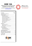
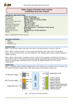
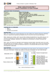
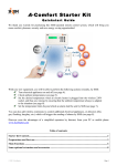
64-311-05_001-Manual-AGG-3_Rev1.0-ENG.doc
Page 1
AGG 3
Power generator controller.
Extension for SMS-operated Alarm & Switch Controller Sikom GSM 12A.
Installation and User Manual
1.
OVERVIEW OF AGG 3 ................................................................................................................. 2
2.
CONNECTIONS ............................................................................................................................. 3
2.1. CONNECTION TO GSM 12A .......................................................................................................... 3
2.2. CONNECTION TO THE POWER GENERATOR ..................................................................................... 3
2.3. CONNECTION TO THE POWER SUPPLY ............................................................................................ 3
3.
CONFIGURATION ........................................................................................................................ 5
3.1. ADJUSTING THE START-UP PARAMETERS ....................................................................................... 5
4.
OPERATING THE GENERATOR................................................................................................ 6
4.1. HOW TO SEND SMS COMMANDS ................................................................................................... 6
4.2. OPERATION BY MEANS OF SMS COMMANDS.................................................................................. 6
4.3. STARTING & STOPPING THE GENERATOR ....................................................................................... 6
4.3.1. Starting the generator............................................................................................................ 6
4.3.2. Possible faults ....................................................................................................................... 6
4.3.3. Stopping the generator .......................................................................................................... 7
5.
TROUBLESHOOTING .................................................................................................................. 7
6.
PRECONDITIONS AND ADVICE ................................................................................................ 8
7.
TECHNICAL SPECIFICATIONS ................................................................................................. 8
8.
RECYCLING INFORMATION..................................................................................................... 9
9.
WARRANTY................................................................................................................................... 9
© EcoStarter / Hulaas IT Solutions, 2010
Page 2
64-311-05_001-Manual-AGG-3_Rev1.0-ENG.doc
1. Overview of AGG 3
Push-buttons for controlling the generator manually:
stop
start
Output relays for start and ignition
Input for start detection
Data to/from GSM 12A
Output relay for load connection order
Fig. 1. Overview of AGG 3
•
•
•
•
•
3 output relays rated 16A 50VDC :
o ignition (”TENNING”)
o start (”START”)
o load connection (”LAST”).
2 push-buttons for local start/stop of generator.
4 LEDs:
o power (”POWER”, for AGG 3 itself)
o fault (”FEIL”)
o running status of generator: start (”START”) and running (”DRIFT”).
Input for monitoring of engine rotation (”SENSE”).
Data bus (”DATA A”, ”DATA B”) for connecting to GSM 12A.
64-311-05_001-Manual-AGG-3_Rev1.0-ENG.doc
Page 3
2. Connections
The following connections are required before using AGG 3.
2.1. Connection to GSM 12A
AGG 3 must be connected to GSM 12A in order to be operated remotely.
Connect terminals “DATA A” and “DATA B” of AGG 3 to “DATA A”, respectively “DATA B” of GSM 12A
(cf. Fig. 2).
2.2. Connection to the power generator
Relay contacts ”TENNING” (ignition) and ”START” (start) of AGG 3 are to be connected to the power
generator so that they replace the ignition key and the start switch (cf. Fig. 2).
The relay labelled ”LAST” (load) is designed to activate an auxiliary relay, which in turn connects the
load that consumes the generated power.
NB! This auxiliary relay must be rated to stand the load consumption!
The auxiliary relay is to be mounted in series on the live 230V phase output of the generator (cf. Fig. 2)
so that the load only gets connected once the generator has reached a sufficient rotational speed and the
engine has run warm enough. Some generators get damaged when started under load. The delay before
connecting the load is adjustable with AGG 3: please refer to the manual of the generator for adjusting
this delay correctly.
The terminal pair labelled ”SENSE” constitutes a voltage measurement input used by AGG 3 for
determining if the generator has started and is running.
This input is polarity independent. The starter motor will be disconnected when the voltage reaches a
user-defined threshold between the two SENSE–terminals or between one of the SENSE inputs and GND.
The generator engine will be considered as started and running as long as the measured voltage is higher
than this threshold. Max voltage on SENSE input: 16V.
Some generators have a 12V charging output that can be used for this purpose, but then the charging
output will not be usable simultaneously for charging. If the generator has no charging output, use instead
its 230VAC output with an auxiliary relay (depending on the generator type) to determine if the start is
successful or not.
A third alternative is to mount an RPM rotational speed monitor and to adjust it for use with AGG 3.
2.3. Connection to the power supply
Connect the power supply (necessary for powering on AGG 3) to terminals +12 volt and GND.
NB! Do not power on AGG 3 before all other connections are done.
© EcoStarter / Hulaas IT Solutions, 2010
Page 4
Fig. 2. Connections between AGG 3, GSM 12A and the power generator
64-311-05_001-Manual-AGG-3_Rev1.0-ENG.doc
64-311-05_001-Manual-AGG-3_Rev1.0-ENG.doc
Page 5
3. Configuration
AGG 3 must not be powered on before all connections have been made. Once powered, its LED labelled
”POWER” will turn on.
NB! DO NOT START TH E GENERATOR BEFORE ALL START-UP
PARAMETERS HAVE BEEN ADJUSTED!
3.1. Adjusting the start-up parameters
The start-up parameters of AGG 3 are set by sending SMS commands to GSM 12A. Several commands
may be combined within a single SMS message.
E.g.: the SMS 1234 F09 E00 H03 sets voltage threshold to 9V, start motor disconnection delay to 0
seconds, and load connection delay to 3 minutes.
F
Voltage threshold for start detection
Command F sets the voltage threshold that will disconnect the start motor as soon as the generator engine
is running. This threshold is influenced by the method used for monitoring the rotational speed.
The start motor gets disconnected once the “SENSE” input is higher than this threshold.
E.g.: 1234 F07 for disconnecting at 7V (the voltage is always written with 2 digits)
E.g.: 1234 F10 for disconnecting at 10V
NB!
Max. 15V!
E
Delay before disconnecting the start motor
Command E sets the delay before disconnecting the start motor, after the voltage threshold set with F has
been reached. This is to fine-tune the disconnection point.
E.g.: 1234 E00 sets no delay (the delay is always written with 2 digits)
E.g.: 1234 E13 sets a delay of 1.3 seconds before the disconnection
NB!
Max 1.5 seconds!
Voltage threshold and disconnection delay must be determined experimentally. Start with a low voltage
threshold and increase it gradually until an adequate level is found. Stop the generator with the left-hand
push-button of AGG 3 if the start engine does not get disconnected in time.
H
Delay before connecting the load
The connection of the load may be delayed for some minutes after the generator has started. This is to
prevent possible damage to the generator engine by letting it run warm before it gets loaded.
Command H is followed by the delay in minutes before the load is connected.
NB! Please refer to the manual of your generator for the recommended delay.
E.g.: 1234 H00 sets no delay (the delay is always written with 2 digits)
E.g.: 1234 H03 sets a delay of 3 minutes after start before the load is connected
NB!
Max 15 minutes!
Page 6
64-311-05_001-Manual-AGG-3_Rev1.0-ENG.doc
4. Operating the generator
GSM 12A and AGG 3 are configured and controlled by means of regular SMS messages sent from
mobile phones. The factory-set personal access code 1234 will be used in the following examples. You
should set a new access code as soon as possible – and remember it!
4.1. How to send SMS commands
SMS messages must always contain the following:
• First, the 4-digit access code
• Then, any control commands (several can be sent in the same SMS)
Send SMS commands to AGG 3 by using the phone number of the SIM card inside your GSM 12A.
4.2. Operation by means of SMS commands
Q
Start/stop generator, request status
Command Q is followed either by 0 for stop, 1 for start or 2 for requesting current status and
configuration parameters.
E.g.:
E.g.:
E.g.:
1234 Q1 starts the generator
1234 Q0 stops the generator
1234 Q2 requests an SMS with current status and configuration parameters
4.3. Starting & stopping the generator
The generator can be started/stopped manually (with the push-buttons of AGG 3) or with SMS messages.
Error and start/stop follow-up messages are sent to the mobile phone number stored inside GSM 12A.
However, explicitly requested status messages (with command Q2) are sent to the requesting phone.
4.3.1. Starting the generator
Once the start button has been depressed (during approx. 1 second), or an SMS containing the start
command has been received, the LED labelled ”START” will turn on and the ignition start. After a few
seconds, the start motor will run until it has been detected that the generator engine has started. The start
motor will run for at most 15 seconds. A new attempt will take place after a pause of 30 seconds in case
of failure.
If the generator engine does not run after 5 attempts, ignition will be switched off and an SMS sent with
the message ”Error: Generator does not start!”. Further attempts may be ordered by sending
the start command again.
Once the generator engine has started, the load will be connected after some minutes (programmable
delay 0 – 15min). The LED labelled ”DRIFT” will then turn on and an SMS with the message
”Generator started!” sent off.
4.3.2. Possible faults
If the generator stops during operation (e.g. if it runs out of fuel), the load will get disconnected, ignition
switched off and the SMS message ”Error, generator stopped!” sent off.
64-311-05_001-Manual-AGG-3_Rev1.0-ENG.doc
Page 7
The LED labelled ”ERROR” will blink red to signal the fault. It will not be allowed to start the generator
again before the issue has been solved and the stop button of AGG 3 briefly pushed to reset the fault
status.
4.3.3. Stopping the generator
The generator is stopped either by depressing the stop button of AGG 3 or by sending the stop command
by SMS. The load will then be disconnected and ignition switched off.
AGG 3 will check if the generator engine has really stopped before sending the confirmation message
”Generator stopped!”. If the engine does not stop within 12 seconds (useful for diesel engines), the
message ”Error: Generator does not stop!” will be sent. The LED labelled ”ERROR” will
blink red to signal the fault. The stop button of AGG 3 must be briefly operated to stop the generator and
reset the fault status.
5. Troubleshooting
No light from any LED:
• Is the power supply of GSM 12A and AGG 3 connected (terminals +12V and GND) correctly?
• Does the battery (or other power supply) provide sufficient voltage/power?
LED labelled ”ERROR” blinks:
• The generator has stopped because of a fault (no fuel?).
• The generator did not stop at command.
• Problem with RPM (engine rotation speed) monitoring.
No contact by SMS:
• Please consult the manual of GSM 12A.
Message ”Generator does not stop” is received:
• Please consult the manual of the generator.
Page 8
64-311-05_001-Manual-AGG-3_Rev1.0-ENG.doc
6. Preconditions and advice
• In an SMS, 1 always means ON and 0 (zero) is always OFF.
• Uppercase and lowercase letters can be used equally in commands.
E.g., S is the same as s.
• The 4-digit personal access code always comes as the first 4 characters of a message.
• Space characters (blanks) may be used between commands, but not inside a command:
e.g., 1234 R1 is valid, but 1234 R 1 will not be understood.
• Commands sent to GSM 12A/AGG 3 may be combined inside a same SMS message:
e.g., 1234 R1 S activates relay #1 and requests a status message.
• Always wait 1 minute or more between each SMS message sent to GSM 12A (messages may take
some time to be delivered).
7. Technical specifications
Manufacturer:
Sikom AS, Norway
Model:
AGG 3
Operating voltage:
7.5 – 15.0 V DC
Relays:
16A - 50V (use an auxiliary relay for connecting the load to the generator!)
Max voltage on SENSE input: 16V
Consumption:
22 mA (standby)
Operating temperature:
-20 to +50 ºC
Dimensions (LxDxH):
111 x 28 x 62 mm
Weight:
130g
AGG 3 is designed for indoor use only.
This equipment complies with the European R&TTE directive.
Further information may be obtained by contacting either the Swiss importer through
www.EcoStarter.com or the manufacturer:
Sikom AS
Jernbanegata 16/18
P.O. Box 223
7601 Levanger
Norway
Internet address: www.sikom.no
64-311-05_001-Manual-AGG-3_Rev1.0-ENG.doc
Page 9
8. Recycling information
The WEEE (Waste Electrical and Electronic Equipment) symbol indicates that this product must not be
disposed of along with other household waste. It is the customer's responsibility to dispose of the product
properly by taking it to a designated site for recycling. To locate a recycling/disposal site near you,
contact your local city recycling program, your regular waste disposal service or the agent from whom
you purchased this product.
For Switzerland, this product includes in its purchase price a contribution (the advanced recycling fee) to
the SWICO Recycling Warranty, which means that used equipment can be handed in free of charge for
recycling. Collection sites are listed at www.swicorecycling.ch.
9. Warranty
Sikom A.S. products are covered by a two years warranty against any faults due to material flaws or
manufacturing errors, which limit or render useless certain functions described for the product. The
warranty requires the customer to present the original bill, with date of purchase and type of equipment
clearly readable.
What is covered by the warranty?
During the warranty period, Sikom A.S. reserves the right to repair the product or to replace defective
parts with functionally equivalent parts. If, after several attempts, Sikom A.S. is unable to correct the
problem, and the product does not work as described in the manual, Sikom may elect to refund the
purchase price or to replace the product with a functionally equivalent one. All replaced parts and
products become the property
of Sikom A.S.
What is not covered by the warranty?
• Indirect damage to life, health, property, revenue and environment caused by circuits and
appliances connected to the unit (install and use this product responsibly).
• Costs related to (re)installing, transporting and dismantling units; recycling may be governed by
special rules (see the relevant chapter).
• Damages caused by use outside of the operating conditions specified in the manual.
• Malfunctions caused by transport damages.
• Any unauthorized repair, modification or disassembly.
• Use of non-original parts.
• External factors, such as lightning, power supply issues, mobile network issues, flood damage or
fire.
• Units with modified, removed or unreadable serial number.
Sikom assumes no responsibility for any errors that may appear in this manual.
Information contained herein is subject to change without notice.