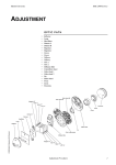
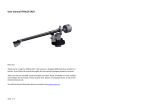
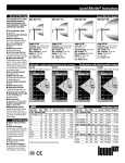
1
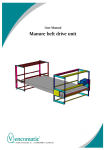
Installation Manual Vencobelt 40 ALU IM Vencobelt-02-en/March ’04 Vencomatic B.V. - Nederland © 2001 Vencomatic ® B.V. – Nederland All rights reserved. The provided information can in no way be reproduced and/or published, in any form or by any means (electronic of mechanical), without prior written permission from Vencomatic ® B.V. The provided information is based on general data concerning the -at the time of the release known- constructions, material characteristic and work methods, so changes are reserved. The provided information is valid for the product in the standard type. Vencomatic ® B.V. can therefore not be held responsible for damage resulting from a standard type deviant specification of the product. The provided information is made with all possible care, but Vencomatic ® B.V. cannot be held responsible for errors or the results of errors in the information. The by Vencomatic ® B.V. used usernames, trading names, trademarks, etc can according to trading laws not be used. Table of contents Vencobelt 40 ALU ................................................................................................................................ 1 1 FOREWORD...............................................................................................................................5 1.1 1.2 1.3 1.4 1.5 1.6 1.7 1.8 1.9 1.10 1.11 1.12 2 2.1 3 3.1 3.2 3.3 3.4 3.5 3.6 4 4.1 5 5.1 6 6.1 6.2 6.3 6.4 7 7.1 7.2 7.3 7.4 7.5 7.6 7.7 7.8 8 8.1 8.2 8.3 9 9.1 9.2 This installation manual ....................................................................................................... 5 Document codes .................................................................................................................. 5 Stickers on the machine ...................................................................................................... 6 Icons in this document ......................................................................................................... 7 Available documentation...................................................................................................... 7 List of terms.......................................................................................................................... 8 Service and technical support ............................................................................................. 8 Identification of the system .................................................................................................. 9 The machine and the environment ...................................................................................... 9 Discard the machine ............................................................................................................ 9 General safety instructions ................................................................................................ 10 Tools................................................................................................................................... 11 GENERAL DESCRIPTION.....................................................................................................12 Description Vencobelt ........................................................................................................ 12 TECHNICAL DATA..................................................................................................................13 Technical data drive unit .................................................................................................... 13 Technical data section ....................................................................................................... 14 Technical data corner ........................................................................................................ 15 Technical data incline / decline set.................................................................................... 16 Technical data return unit .................................................................................................. 17 Technical data oil lubrication system................................................................................. 18 TRANSPORT............................................................................................................................19 Transport safety regulations .............................................................................................. 19 STORAGE .................................................................................................................................20 Storage safety regulations ................................................................................................. 20 PREPARATIONS.....................................................................................................................21 Preparing safety regulations .............................................................................................. 21 Bill of material system ........................................................................................................ 21 Unpack ............................................................................................................................... 21 Preparing installation ......................................................................................................... 21 INSTALLATION........................................................................................................................22 Drive unit ............................................................................................................................ 22 Connecting plate ................................................................................................................ 23 Legs.................................................................................................................................... 24 Incline / decline set ............................................................................................................ 27 Section ............................................................................................................................... 29 Corner ................................................................................................................................ 30 Return unit.......................................................................................................................... 30 Oil lubrication unit .............................................................................................................. 31 ADJUSTMENTS.......................................................................................................................33 Adjusting height of the machine ........................................................................................ 33 Level the machine.............................................................................................................. 33 Secure the machine........................................................................................................... 33 FINISHING.................................................................................................................................34 Slide profile ........................................................................................................................ 34 Chain guides ...................................................................................................................... 36 IM Vencobelt-02-en/March ’04 3 9.3 9.4 9.5 Brushes .............................................................................................................................. 38 Dirt tray............................................................................................................................... 38 Laminaeplug....................................................................................................................... 39 10 OPTIONS..........................................................................................................................40 10.1 10.2 10.3 Paper roll ............................................................................................................................ 40 Corner with bend 0-180 degrees ....................................................................................... 40 Drive unit type VB40ALU NEMA-flange / Japan ............................................................... 40 11 INDEX ...............................................................................................................................41 IM Vencobelt-02-en/March ’04 4 1 Foreword 1.1 This installation manual This manual is meant as reference book for the machine that is represented on the cover of this document. Only authorized technicians and authorized users are allowed to move, install and place this equipment in operation in a safe and responsible way. You can find information about the operation, periodic adjustment, cleaning and maintenance on the machine in the user manual. All chapters and paragraphs have a document code. You will find this code at the bottom of every page. 1.2 Document codes The document codes consists of six parts: • • • • • • Field 1: document type Field 2: product type Field 3: version number Field 4: language code Field 5: month of publication Field 6: year of publication IM Vencobelt-02-en/March ’04 5 1.3 Stickers on the machine Following stickers are applied to the machine. See picture below. IM Vencobelt-02-en/March ’04 6 1.4 Icons in this document In the manual of this machine the following icons are used: Careful Procedures that can cause damage to the product, surroundings or environment. This damage can occur if procedures are not carried out carefully. Warning Danger for electricity / electrical power. Remarks, suggestions and advices. Pull out the plug first before proceeding operation. Consult the indicated Information source first. Protect against water and moisture. Watch out! Procedure that needs extra attention. 1.5 Available documentation The following documentation of the Vencobelt is available: • • user manual (Vencobelt 01-en/August-2001) installation manual (Vencobelt-01-en/August-2001) IM Vencobelt-02-en/March ’04 7 1.6 List of terms In this manual the following terms are used: Technician A trained -and therefore acquainted with the applied technique- expert familiar with the possible dangers of the machine. Technicians have a minimum age of 19 years. The have a solid knowledge of transport techniques. Technicians are authorized to transport, install, place in operation and repair the machine. Authorized user See 'User'. The 'authorized user' is also authorized to install and commision the machine. User The customer using the machine according to the purpose recorded in the concerning user manual. The user is responsible for the operation and the in the user manual described periodic adjustment, cleaning and maintenance of the machine. Conveyor belt system Indication for all possible versions of this machine. Component Identification for every separate connectable part of the machine. Flock Indication for the economic life cycle of the chickens. 1.7 Service and technical support When an item is not discussed in this manual contact your local Vencomatic dealer for information about specific procedures. If you need to call your dealer, always mention the registration number of the machine. You can find this number on the production label of the machine on the drive unit. See 'Identification of the system'. IM Vencobelt-02-en/March ’04 8 1.8 Identification of the system The production label is placed on the drive unit. See picture below. The number on the production label represents the order number. 1.9 The machine and the environment 1.9.1 Packaging material The packaging material mainly consists of: • • • (corrugated) cardboard (untreated) wood plastic packaging material Inform the customer to inquire about the possibilities for recycling and environmentally friendly disposal \ re-use of the packaging materials. 1.10 Discard the machine Discarded machines should be disposed of in an environmentally friendly way according to the local regulations. The used materials can be subdivided roughly in: • • • • • • plastic (egg carrier on chain, dirt tray, various plugs) untreated metal (shafts) coated metal (motor and bearing block) galvanized metal (sheet metal, fastening materials, legs) aluminum (side profiles of section) oil and grease (in motor, bearing block and oil lubrication system) If an electrical control panel is supplied: The printed circuit board(s) and their components in the control panel are electrical waste. IM Vencobelt-02-en/March ’04 9 1.11 General safety instructions Vencomatic B.V. will not accept any claim for damage or injury caused by not following the safety regulations and safety instructions, or carelessness during: • • • • • • transport, installation, commissioning, operation, maintenance, troubleshooting and repair, of the machine and possible accessories. Depending on specific working circumstances or additional accessories, additional safety regulation can be needed. If during previous the aforementioned activities a potential danger occurs, please contact Vencomatic B.V. immediately. 1.11.1 • • • • Installation manual / user manual Every technician has to know the contents of the installation manual. The technician must follow the instructions in the installation manual conscientiously. Every (authorized) user has to know the contents of the user manual and follow the instructions in the user manual conscientiously. Never change the order of the “to do” actions. Store this manual carefully. 1.11.2 Stickers and instructions on the machine Stickers, symbols and instructions are an integral part of this machine’s safety precautions. It is therefore not allowed to cover them up and / or remove them. They have to be present and legible during the whole life cycle of the system. • Replace or repair illegible stickers, symbols and instructions immediately. 1.11.3 Technician Transport, installation and commissioning of the machine is allowed for authorized and trained technicians only. (See 'Terms and Definitions'.) While carrying out their work they are always fully responsible for compliance of local safety regulations and guidelines. Temporary personnel and persons in training are allowed to work with the machine under supervision of an authorized technician only. 1.11.4 Authorized users An authorized user is the customer using the machine. This use is in accordance with the purpose of the user guide. The user is responsible for the operation of the machine. The user takes care of periodic adjustment, cleaning and maintenance of the machine. These items are written down in the user manual. The ‘authorized user’ is also authorized for installation and commissioning of the machine. 1.11.5 Technical specifications The technical specifications cannot be changed. IM Vencobelt-02-en/March ’04 10 1.11.6 Modifications Modification of (parts of) the machine is not allowed. Use original (spare)parts advised by the manufacturer only. 1.12 Tools 1.12.1 Added tools The following tools have been included with your system: • • • • crosshead bit for taptite screw 7 mm iron drill 5,5 mm iron drill 10 mm/¼” drive socket wrench 1.12.2 Remaining tools: All other tools which are necessary for installation of the machine are shown as icons in the following drawings. IM Vencobelt-02-en/March ’04 11 2 General description 2.1 Description Vencobelt The Vencobelt is made up of modular components. This means that –depending on the use of the component- different positions are possible. • • The maximum capacity of the Vencobelt is 25,000 eggs per hour. The belt speed is 4.5 meter/minute with the electric motor running at 50 Hz. The following components can be part of the Vencobelt. • • • • • • • 319500/6/7/10/11 319501 319503 319504/8/9 319502 316634 949114 : : : : : : : IM Vencobelt-02-en/March ’04 drive unit section incline / decline set corner return unit oil lubrication system binder with bill of material and manuals 12 3 Technical data 3.1 Technical data drive unit 3.1.1 General drive unit Omschrijving Torque (Nm) Max. effective Vencobelt length (m) (ft) VB40ALU 110 Nm 110 25 82 VB40ALU 210 Nm 210 50 164 VB40ALU 310 Nm 310 100 328 VB40ALU NEMA-flange * variable 75 246 VB40ALU Japan 310 100 328 * motor type to be installed after consultation with dealer. 3.1.2 Dimensions drive unit All motor versions have the same dimensions. IM Vencobelt-02-en/March ’04 13 3.1.3 Electrical installation drive unit Description Power Mains voltage VB40ALU 110 Nm 370 Watt 3x230 / 3x400 V VB40ALU 210 Nm 550 Watt 3x230 / 3x400 V VB40ALU 310 Nm 550 Watt 3x230 / 3x400 V VB40ALU NEMA-flen* 0.5 hp 0.75 hp 550 Watt 1x230 V 60Hz 1x230 V 60Hz 3x230 / 3x400 V VB40ALU Japan * motor type to be installed after consultation with dealer. Electrical data is subject to changes. 3.2 Technical data section 3.2.1 General section Description General Material Aluminum 3.2.2 Dimensions section IM Vencobelt-02-en/March ’04 14 3.3 Technical data corner 3.3.1 General corner Description Angle of corners Corner VB40ALU 90 degrees 90 degrees Corner VB40ALU 45 degrees 45 degrees Corner VB40ALU degrees 0-90 degrees 3.3.2 Dimensions corner IM Vencobelt-02-en/March ’04 15 3.4 Technical data incline / decline set 3.4.1 General incline / decline set Description An incline / decline set always contains an inclining, a declining component and a plough. The maximum angle is 28 degrees. 3.4.2 Dimensions incli ne / decline set IM Vencobelt-02-en/March ’04 16 3.5 Technical data return unit 3.5.1 General return unit Description On the return unit a rotating cleaning brush is mounted. The cleaning brush cleans the egg carriers on the chain. 3.5.2 Dimensions return unit IM Vencobelt-02-en/March ’04 17 3.6 Technical data oil lubrication system 3.6.1 General oil lubrication system Description Quantity / unit Manufacturer Buijer Qmax 0,01 cc/minute Pmax 4,1 bar Volume oil reservoir 1.8 liter Oil type Paraffinum perliquidum PH. EUR. 99 3.6.2 Dimensions oil lubrication unit 3.6.3 Electrical installation oil lubrication system Description Unit Frequency 50/60 Hz Voltage 230 Volt Capacity Max. 5 Watt IM Vencobelt-02-en/March ’04 18 4 Transport 4.1 Transport safety regulations See also 'General safety instructions'. IM Vencobelt-02-en/March ’04 19 5 Storage 5.1 Storage safety regulations • • • • • See also 'General safety instructions'. Respect the surrounding conditions. Never store the system in a room where the temperature can get under +10 °C. Lower temperatures can damage sensitive parts. Store the conveyor belt system in a dry and dust free room. Place the conveyor belt system on a level floor. Never place heavy products on top of lighter products. IM Vencobelt-02-en/March ’04 20 6 Preparations 6.1 Preparing safety regulations • • • Always carefully look at the icons in the drawings before starting. Icons give information about which tools to use or the actions to be taken for correct assembly. Take care of scaffolding materials in case work has to be done on a higher level. See also 'General safety instructions'. 6.2 Bill of material system Check if all components and parts are supplied conform to the bill of material. When a component or part is not present contact the local Vencomatic dealer. See ‘Service and technical support’. 6.3 Unpack All boxes are numbered. The numbers on the boxes correspond with the numbers on the bill of material. Leave all components and parts in the boxes as long as possible, this makes the installation easier. 6.4 Preparing installation Make sure that before starting the installation: • • • • the room temperature is 10 °C minimum. the floor is level and paved. all electrical connections are ready for use. the building is ready. IM Vencobelt-02-en/March ’04 21 7 Installation Read ‘This installation manual’ first before starting installation. 7.1 Drive unit 7.1.1 Fixing adjustable foot 1. Turn the drive unit (319500) up side down on a soft floor. 2. Thread the adjustable foot (314327) into the legs, fasten them by hand. 3. Put the drive unit back in normal position again. 7.1.2 Adjusting height drive unit 7.1.2.1 Adjusting height drive unit with collecting table 1. Loosen the adjustable foot (314327) nut. 2. Adjust the height of the drive unit (319500). 3. Lock position of the adjustable foot with the nut. Make sure the working height (H) of the collecting table is adjusted to the length of the person working to the collecting table. Bear in mind the local labour legislation. IM Vencobelt-02-en/March ’04 22 7.1.2.2 Drive unit height adjustment when using an egg packer 1. Loosen the adjustable foot (314327) nut a little. 2. Adjust the height of the drive unit (319500). 3. Fasten the adjustable foot (314327) with the nut. Make sure the height of the drive unit is adjusted to the length of the packer. The height normally varies between 950 en 1050 mm. 7.1.3 Electrical installation drive unit Electrical installation has to be carried out by an official installer. 7.2 Connecting plate Always fix the connecting plate to the inside of the component. 7.2.1 Join two components together 1. Attach the two connectingplates (314314) with two taptites each (911062) to one of the components. 2. Connect the two components. 3. Screw in the remaining taptites. IM Vencobelt-02-en/March ’04 23 7.2.2 Join a section and a bend together 1. Attach the two connetingplates (314314) with two taptites (911049) each to the bend (319503). 2. Connect the two components. 3. Screw in the remaining taptites. 7.3 Legs 7.3.1 Leg for floor positioning 7.3.1.1 Assemble leg for floor positioning 1. Saw off the leg (314288) in correct length with a hacksaw. 2. Push the laminaeplug (314328) into the leg. 3. Screw the adjustable foot (314327) in the leg. 7.3.1.2 Attach leg holder Attach leg holder (314302) with 2 taptites M6 x 12 (911553). Always use connectingplate (911553). IM Vencobelt-02-en/March ’04 24 7.3.1.3 Fix leg for floor positioning 1. Slide the leg (314288) into the leg holder (314302). 2. Adjust the height and lock into position with M8 x 16 bolt (311192). 7.3.2 Leg for ceiling positioning 7.3.2.1 Assemble leg for ceiling positioning 1. Drill 2 holes in the ceiling. 2. Fix the adjustable foot (314327) on the ceiling with the head wood screws (911499) the washers (311199) and the anchors (922129). 3. Saw off the leg (314288) to correct length with a hacksaw. 4. Push the laminaeplug (314328) into the leg. 5. Screw the adjustable foot (314327) in the leg. 6. Drill a ∅ 5,5 hole in the leg. 7. Screw the taptite M6 x 10 (911049) into the laminaeplug (314328). IM Vencobelt-02-en/March ’04 25 7.3.2.2 Fix leg holder ceiling positioning See ‘Fix leg holder‘. 7.3.2.3 Fix leg holder ceiling positioning 1. Slide the leg holder (314302) over the leg (314288). 2. Adjust the hight and fasten bolt M8 x 16 (311192). 7.3.3 Additional leg This action is applicable to ceiling- and floor positioning. Use the little holes in the leg holder as template for the section. Attention! Make sure the centerline of the holes pierce the upper and lower line of the section. 1. Drill 2 holes ∅ 5,5 in the section. 2. Put the leg holder (314302) against the section with the little holes. 3. Fasten 2 M6 x 12 countersunk taptites (911553). IM Vencobelt-02-en/March ’04 26 7.4 Incline / decline set 7.4.1 Fixing incline / decline set IM Vencobelt-02-en/March ’04 27 7.4.2 Maximum incline / decline angle The maximum incline / decline angle is 28°. When the angle is larger than 28° there is a possibility that the eggs will roll back. 7.4.3 Attaching incline / decline set 7.4.3.1 Join together incline / decline set to drive unit 1. Fix the short sections (314354) to the drive unit (319500). See ‘join together two components’. 2. Fix the short section to the incline / decline set and to drive unit. See ‘Join together incline / decline set to a section’. IM Vencobelt-02-en/March ’04 28 7.5 Section 7.5.1 Preassembly Fix the side profile (314305) and distance bar (314304) with the taptites (911062). 7.5.2 Cut off profile 1. Saw off side profile (314305) to correct length with a hacksaw. 2. Place one side plate with the end holes on top off the shortened side profile; make sure the ends are placed equally. 3. Mark and drill the holes. 7.5.3 Fixing section See ’Join together’. IM Vencobelt-02-en/March ’04 29 7.6 Corner 7.6.1 Corner variations The various corners (314504/8) can be used in both left and right hand configurations. 7.6.2 Fixing corners See ‘Join together two components’. 7.7 Return unit 7.7.1 Fixing return unit The return unit is supplied assembled. See “Join together two components”. IM Vencobelt-02-en/March ’04 30 7.8 Oil lubrication unit 7.8.1 Fixing oil lubrication unit Fasten oil lubrication unit (316634) to the drive unit (319500) with 2 taptites (911049). This is possible on position (A) as well as on position (B). 7.8.2 Pre-assembly oil brush 1. Attach the oil brushsystem (316631) to the bracket lubricationbrush (310441). 2. Attach the coupling oil lubricationunit (316633) to the brush lubricationunit (316631). 3. Attach the dosager oil lubricationunit (316632) to the coupling oil lubricationunit (316633). 4. Slide the cutring bold (316636) on the hose oil lubricationunit (316638). 5. Slide the cutring bold (316635) on the hose oil lubricationunit (316638). 6. Attach the cutring bold (316636) to the dosager oil lubricationunit (316632). 7.8.3 Fixing oil brush to drive unit 1. Attach the brush block to the distance holder with M6 x 40 bolt (131132) and nut (641061). 2. Feed the oil line trough the hole (A) in side plate. IM Vencobelt-02-en/March ’04 31 7.8.4 Connecting oil lubrication unit 1. Slide the cutring nut (316637) on the hose oil lubrication unit (316638). 2. Slide the cutring nut (316635) on the hose oil lubrication unit (316638). 3. Attach the cutring nut (316637) to the oil lubrication unit (316634). IM Vencobelt-02-en/March ’04 32 8 Adjustments 8.1 Adjusting height of the machine Rough adjustment: 1. Loosen the bolt (311192) on the leg holder (314302). 2. Adjust the height. 3. Fasten the bolt. Precise adjustment: 4. Turn the nut of the adjustable foot (314327) left (=up) or right (=down). 8.2 Level the machine Start leveling the return unit and work your way towards the drive unit. 1. Place the water-level on the component. Level the water-level by changing the height of the adjustable foot. 2. Repeat this action in the order of the pattern on the drawing. 3. Level all components this way (using the water-level). See also ‘Adjusting height of the machine’. 8.3 Secure the machine 1. Drill 2 holes. 2. Secure the machine with the hexagonal head wood screws (311499), washers (311199) and the plugs (922129). IM Vencobelt-02-en/March ’04 33 9 Finishing Read ‘This installation manual’ first before starting installation. 9.1 Slide profile 9.1.1 Preparation of slide profile If the room temperature is approximately 10 to 15 °C: Put the slide profile (314306) in water of approximately 20 °C for 10 minutes.The material will become supple and easy to handle. 9.1.2 Required room condition slide profile The slide profile is much easier to work with if the room temperature is approximately 20° C (68°F). 9.1.3 Fixing top slide profile 9.1.3.1 1. 2. 3. 4. 5. 6. Fixing slide profile near return station Push the slide profile (314306) into the channel section. Drill a hole ∅ 5,5 mm through the slide profile in the channel section. Pull slie profile back out of groves. Re drill the hole in the slide profile a little with a countersink bore. Push the slide profile (314306) in the channel section. Fasten the slide profile with a countersunk head taptite (911553) to the channel section. IM Vencobelt-02-en/March ’04 34 9.1.3.2 Fixing slide profile on section 1. Hold the slide profile (314306) perpendicular to the channel section. 2. Push the slide profile solidly into the channel section. 9.1.3.3 Fixing slide profile on incline bent 1. Place the slide profile (314306) tension free in the incline corner (319503). 2. Re drill the hole in the slide profile a little with a countesink bore. 3. Fasten the slide profile with a countersunk head taptite (911553) to the plastic block. 9.1.3.4 Fixing slide profile near drive unit See ‘Fixing slide profile near return unit’. IM Vencobelt-02-en/March ’04 35 9.1.3.5 Fixing slide profile on bend Carry out this action with 2 persons. 1. Wrap a hot cloth around the slide profile, it will now become supple. 2. Hold the slide profile (314306) perpendicular to the channel section. 3. Fasten the slide profile. 9.2 Chain guides 9.2.1 Adjust and fasten chain guide 1. Place the chain guide in the middle. 2. Fasten the chain guide with two adjusting rings. 3. Repeat this aktion for all chain guides. 9.2.2 Prepare chain assembly When enough room is available: Unwind the ‘egg carrier+chain’ (314807) on the floor. Do this at the return unit (318306) side. Otherwise place the box in front off the return unit. 9.2.3 Chain assembly 9.2.3.1 Feed chain in return unit Feed in the chain (314807) carefully at the bottom of the return unit (318306). IM Vencobelt-02-en/March ’04 36 9.2.3.2 Feed-through chain in bend Feed the chain (314807) carefully trough the guide profile of the bend (319054/8/9). 9.2.3.3 Chain lead through in drive unit Lead the chain (314807) carefully through the drive unit (319500) till 0.5 meter past the drive wheel. 9.2.3.4 Join together chain ends 1. Cover up the teeth of the return unit with cardboard. 2. Pull the chain (314807) over the belt up to the drive unit. 3. Saw off the chain in the correct length. The chain should be pulled taut enough. 4. Join the chain ends using the chain-closing link (316505). 5. Mark the egg carrier near the chain-closing link with paint, this makes it easy to find the link in the future. IM Vencobelt-02-en/March ’04 37 9.2.4 Tighten chain Tighten or loosen tensioner bolt in order to tighten chain (314807) to the correct tension. 9.3 Brushes 9.3.1 Place and adjust brush slat Fix the brush slat (314293) on the conveyer (319500) with 2 taptites (911062) in the predrilled holes. Fix the brush slat on an equal level with the adjoining component. This is done to prevent damaging the eggs. 9.4 Dirt tray 9.4.1 Placing dirt tray to the return unit Hang the dirt tray (336270) with the groove to the boss. IM Vencobelt-02-en/March ’04 38 9.4.2 Placing dirt tray to the drive unit Hang the dirt tray (336270) in the brace and let it rest on the drive unit (319500). 9.5 Laminaeplug 9.5.1 Place laminaeplug on legs IM Vencobelt-02-en/March ’04 39 10 Options 10.1 Paper roll 10.2 Corner with bend 0-180 degrees 10.3 Drive unit type VB40ALU NEMA-flange / Japan IM Vencobelt-02-en/March ’04 40 11 Index A Adjustable feet ................................................................................................................................... 22 Adjusting height.................................................................................................................................. 33 Adjustments ....................................................................................................................................... 33 Authorized user .................................................................................................................................... 8 B Brushes .............................................................................................................................................. 38 C Chain assembly.................................................................................................................................. 36 Chain guides ...................................................................................................................................... 36 Component........................................................................................................................................... 8 Connecting plate ................................................................................................................................ 23 Conveyor belt system .......................................................................................................................... 8 Corner .......................................................................................................................................... 30; 40 technical data ................................................................................................................................. 15 Cut off profile ...................................................................................................................................... 29 D Dirt tray............................................................................................................................................... 38 Discard................................................................................................................................................. 9 Document codes .................................................................................................................................. 5 Drive unit ...................................................................................................................................... 22; 40 adjustable feet ................................................................................................................................ 22 adjusting height .............................................................................................................................. 22 electrical installation ....................................................................................................................... 23 height adjustment........................................................................................................................... 23 technical data ................................................................................................................................. 13 F Finishing ............................................................................................................................................. 34 Flock..................................................................................................................................................... 8 I Icons ..................................................................................................................................................... 7 Identification of the system .................................................................................................................. 9 Incline / decline set ............................................................................................................................ 27 fixing ............................................................................................................................................... 27 maximum incline / decline angle .................................................................................................... 28 technical data ................................................................................................................................. 16 Installation .......................................................................................................................................... 22 preparing ........................................................................................................................................ 21 J Join together two components........................................................................................................... 23 L Laminaeplug....................................................................................................................................... 39 Leg...................................................................................................................................................... 24 Leg for ceiling positioning .................................................................................................................. 25 Leg for floor positioning ..................................................................................................................... 25 Leg for floor postitioning .................................................................................................................... 24 List of terms.......................................................................................................................................... 8 M Machine discard.............................................................................................................................................. 9 Modifications ...................................................................................................................................... 11 IM Vencobelt-02-en/March ’04 41 O Oil brush............................................................................................................................................. 31 Oil brush............................................................................................................................................. 31 Oil lubrication systen technical data ................................................................................................................................. 18 oil lubrication unit ............................................................................................................................... 32 Oil lubrication unit .............................................................................................................................. 31 Options ............................................................................................................................................... 40 P Packaging material .............................................................................................................................. 9 Paper roll ............................................................................................................................................ 40 Preparations ....................................................................................................................................... 21 Preparing safety regulations .............................................................................................................. 21 Production label ............................................................................................................................... 8; 9 R Required room condition slide profile ................................................................................................ 34 Return unit.......................................................................................................................................... 30 technical data ................................................................................................................................. 17 S Safety instructions.............................................................................................................................. 10 Safety regulations preparing ........................................................................................................................................ 21 Section ............................................................................................................................................... 29 fixing ............................................................................................................................................... 29 technical data ................................................................................................................................. 14 Service ................................................................................................................................................. 8 Slide profile ........................................................................................................................................ 34 preparation ..................................................................................................................................... 34 Stickers........................................................................................................................................... 6; 10 Storage............................................................................................................................................... 20 Storage safety regulations ................................................................................................................. 20 T Technical data.................................................................................................................................... 13 Technical specifications..................................................................................................................... 10 Technical support................................................................................................................................. 8 Technician responsibilities ................................................................................................................................ 10 Technician............................................................................................................................................ 8 Transport............................................................................................................................................ 19 Transport safety regulations .............................................................................................................. 19 U Unpack ............................................................................................................................................... 21 User...................................................................................................................................................... 8 responsibilities ................................................................................................................................ 10 V Vencobelt description ...................................................................................................................................... 12 IM Vencobelt-02-en/March ’04 42