1
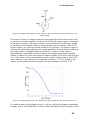
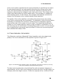
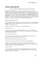
4. Tube Saturator
of the circuit nodes is specified as the input and another is specified as the output.
At each sampling period, the input sample determines the voltage at the input
node. Then the simulator uses iterative numerical methods to solve the set of
equations, determining the voltage at each node in the circuit. The voltage of the
output node determines the output sample value. This procedure is repeated at
each sampling period. In this manner, the simulator automatically converts the
analog circuit schematic into a realtime digital effects algorithm.
The upside of this is the capability to simulate with great accuracy any analog
circuit just by entering the circuit schematic. The downside is that circuit simulation
technology is extremely CPU intensive. Furthermore the computation expense
grows as the cube of the number of circuit nodes. This means that doubling the
number of circuit nodes requires a factor of eight increase in computation. So, for
the time being we are restricted to simulating fairly small circuits. A circuit as large
as a complete guitar amp would require perhaps 50 times more processing power
than available with today's CPUs.
4.4 Tube Saturator Schematics
Tube Saturator combines a Baxandall 3-band equalizer and a two stage triode
preamp. The circuit schematic for the equalizer is given in Figure 4-8.
Figure 4-8. Baxandall style equalizer used in Tube Saturator, derived from version by Chu Moy,
http://www.headwize.com/projects/equal_prj.htm.
The bass control implements a low shelving filter with a transition frequency of
approximately 100 Hz, that is the frequency at which the shelf is at half-height. For
example, when the height is set at +12 dB, the response will be +6 dB at 100 Hz.
23