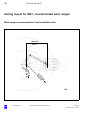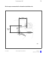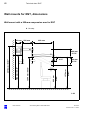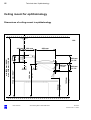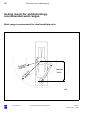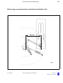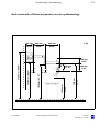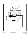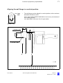
1
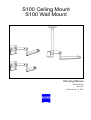
S100 Ceiling Mount
S100 Wall Mount
Planning Manual
M-30-1385-en
Issue 6.0
Printed on 05. 11. 2007
Key to symbols
Different symbols used in this user's manual draw your attention to safety
aspects and useful tips. The symbols are explained in the following.
Warning!
The warning triangle indicates potential sources of danger which may
constitute a risk of injury for the user or a health hazard.
Caution:
The square indicates situations which may lead to malfunction, defects,
collision or damage of the instrument.
Note:
The hand indicates hints on the use of the instrument or other tips for the
user.
OPMI®
OPMI® is a registered trademark of Carl Zeiss.
Contents
M-30-1385-en
S100 product range
5
Ceiling mount
6
Wall mounts
6
Support units
6
General technical data
7
Minimum distances and pivot points
8
Motion ranges of S100 suspension systems
10
Standby positions
17
Installation sites in the OR or the treatment room
18
Technical data / Dentistry
23
Ceiling mount for dentistry
24
Ceiling mount for dentistry, recommended work ranges
26
Wall mounts for dentistry, dimensions
28
Wall mounts for dentistry, recommended work ranges
30
S100 Centro suspension system for dentistry
32
Technical data / ENT
33
Alternative mounting possibilities for OPMI pico in ENT
34
Ceiling mount for ENT
36
Ceiling mount for ENT, recommended work ranges
38
Wall mounts for ENT, dimensions
40
Wall mounts for ENT, recommended work ranges
42
Technical data / Ophthalmology
45
Ceiling mount for ophthalmology
46
Ceiling mount for ophthalmology,
recommended work ranges
48
Wall mounts for ophthalmology
50
Wall mounts for ophthalmology,
recommended work ranges
52
S100 Ceiling Mount S100 Wall Mount
Issue 6.0
Printed on 05. 11. 2007
M-30-1385-en
Technical data of examination units
55
S100 examination unit, with illumination module
56
S100 examination unit including light guide
57
CustomerPs preparatory responsibilities
59
Customer's responsibilities
60
Planning the electrical installation
64
Anchoring of the S100 ceiling mount
66
Anchoring of the S100 wall mount
70
Confirmation of the structural calculation and execution
of installation
75
Index
77
S100 Ceiling Mount S100 Wall Mount
Issue 6.0
Printed on 05. 11. 2007
5
S100 product range
S100 product range
M-30-1385-en
Ceiling mount
6
Wall mounts
6
Support units
6
S100 Ceiling Mount S100 Wall Mount
Issue 6.0
Printed on 05. 11. 2007
6
S100 product range
Ceiling mount
Cat. No.: 1151-515
Wall mounts
with 950mm suspension arm
with 600 mm suspension arm
Cat. No.: 1080-347
Cat. No.: 1148-883
Support units
for attachment to external including light guide and CZ illu- including light guide
examination unit,
mination module
Cat. No.: 1095-091
M-30-1385-en
S100 Ceiling Mount S100 Wall Mount
Cat. No.: 1095-094
Issue 6.0
Printed on 05. 11. 2007
7
General technical data
General technical data
Minimum distances and pivot points
8
Motion ranges of S100 suspension systems
10
Motion range of S100 ceiling mount
10
Motion range of the wall mount with a 950mm suspension arm
12
Motion range of the wall mount with a 600mm suspension arm
14
Standby positions
17
Possible standby positions of the wall mounts
17
Installation sites in the OR or the treatment room
18
Ceiling mount: ideal installation above the patient
18
Ceiling mount: alternative installation to the patient's side
19
Wall mount with a 950mm suspension arm, possible installation sites 20
Wall mount with a 600mm suspension arm, possible installation sites 21
M-30-1385-en
S100 Ceiling Mount S100 Wall Mount
Issue 6.0
Printed on 05. 11. 2007
8
General technical data
Minimum distances and pivot points
Minimum distances
For the installation of the wall mount, please observe the necessary minimum distances from walls as a function of the selected standby position;
also see the drawing below. Please also make sure that the mount cannot
collide with doors or other examination configurations.
Any collisions with doors and other examination configurations must also
be avoided in the case of the ceiling mount.
320 mm
12.60Z
550 mm
21.65Z
1:20
M-30-1385-en
S100 Ceiling Mount S100 Wall Mount
Issue 6.0
Printed on 05. 11. 2007
9
General technical data
Determining the pivot points
The specifications for the installation areas always refer to the pivot points
of the mounts. The illustration below shows you the positions of the pivot
points.
Key
1
Pivot point of wall mount
2
Pivot point of ceiling mount
1
M-30-1385-en
2
S100 Ceiling Mount S100 Wall Mount
Issue 6.0
Printed on 05. 11. 2007
10
General technical data
Motion ranges of S100 suspension systems
Motion range of S100 ceiling mount
Notes:
\ The motion and work range of the suspension system is determined
by the 45° and 122° positions between the suspension arm and the
carrier arm. The system can be easily moved between these two positions, allowing reliable positioning of the surgical microscope.
Plan the location of the suspension system relative to the patient in
such a way that you normally work exactly in the middle between
these two positions. It is possible to move the arms a little beyond the
positions given.
\
The ceiling mount provides a circular motion and work range of 360°.
This is achieved by the swivel range of the carrier arm mounted on the
column of 163° and the possibility of also folding the suspension arm
toward the carrier arm in the opposite direction.
Key
M-30-1385-en
1
45° position of the suspension arm relative to the carrier arm,
corresponds to a radius of 700 mm (27.56")
2
122° position of the suspension arm relative to the carrier arm,
corresponds to a radius of 1,300 mm (51.18")
3
Carrier arm, length 500 mm (19.69"), provides a swivel range of ±163°
about the column, supports the suspension arm
4
Motion and work range of the ceiling mount
5
Suspension arm, length 950 mm (37.40"), provides a swivel range of
±163° relative to the carrier arm
Caution:
When planning and installing the mount, make sure that the orientation of the swivel range is correct.
6
Center of the carrier arm's swivel range relative to the ±163° stops
Caution:
When planning and installing the mount, make sure that the orientation of the swivel range is correct.
S100 Ceiling Mount S100 Wall Mount
Issue 6.0
Printed on 05. 11. 2007
11
General technical data
3
2
6
1
m
m
0
70 6Z
R 2 7 .5
R
m
00 m
3
1
R
.18Z
R 51
4
163°
3°
16
163°
163°
5
5
163°
16
3°
163°
R 51
R 13 .18Z
00 m
m
R
R 27.5
70 6Z
0m
m
163°
4
6
3
M-30-1385-en
2
1
S100 Ceiling Mount S100 Wall Mount
1:20
Issue 6.0
Printed on 05. 11. 2007
12
General technical data
Motion range of the wall mount with a 950mm suspension arm
Notes:
\ The motion and work range of the suspension system is determined
by the 45° and 122° positions between the suspension arm and the
carrier arm. The system can be easily moved between these two positions, allowing reliable positioning of the surgical microscope.
Plan the location of the suspension system relative to the patient in
such a way that you normally work exactly in the middle between
these two positions. It is possible to move the arms a little beyond these positions.
\
The wall mount with a 950mm suspension arm provides a semi-circular motion and work range of 180°. This is achieved by the swivel range of the carrier arm of 105° and the possibility of also folding the
suspension arm toward the carrier arm in the opposite direction.
Key
M-30-1385-en
1
45° position of the suspension arm relative to the carrier arm,
corresponds to a radius of 700 mm (27.56")
2
122° position of the suspension arm relative to the carrier arm,
corresponds to a radius of 1,300 mm (51.18")
3
Carrier arm, length 500 mm (19.69"), provides a swivel range of
±105°, supports the suspension arm
4
Length of the suspension arm, 950 mm (37.40")
5
Center of the carrier arm's swivel range relative to the ±105° stops
6
Motion and work range of the wall mount
S100 Ceiling Mount S100 Wall Mount
Issue 6.0
Printed on 05. 11. 2007
13
General technical data
6
105°
1
m
0m Z
0
6
7
R 27.5
R
2
0 mm
R 130
8Z
R 5 1 .1
5
3
105°
105°
R 950 mm
R 37.40Z
R 37.40Z
R 950 mm
4
4
3
R
R 27.5
70 6Z
0m
m
2
R 51.1
8Z
R 130
0 mm
5
1
105°
6
1:20
M-30-1385-en
S100 Ceiling Mount S100 Wall Mount
Issue 6.0
Printed on 05. 11. 2007
14
General technical data
Motion range of the wall mount with a 600mm suspension arm
Notes:
\ The motion and work range of the suspension system is determined
by the 45° and 122° positions between the suspension arm and the
carrier arm. The system can be easily moved between these two positions, allowing reliable positioning of the surgical microscope.
Plan the location of the suspension system relative to the patient in
such a way that you normally work exactly in the middle between
these two positions. It is possible to move the arms a little beyond these positions.
\
The wall mount with a 600 mm suspension arm provides a semi-circular motion and work range of 180°. This is achieved by the swivel range of the carrier arm of 105° and the possibility of also folding the
suspension arm toward the carrier arm in the opposite direction.
Key
M-30-1385-en
1
45° position of the suspension arm relative to the carrier arm,
corresponds to a radius of 700 mm (27.56")
2
122° position of the suspension arm relative to the carrier arm,
corresponds to a radius of 1,300 mm (51.18")
3
Carrier arm, length 500 mm (19.69"), provides a swivel range of
±105°, supports the suspension arm
4
Suspension arm, length 600 mm (23.62"), provides a swivel range of
±163° relative to the carrier arm
Caution:
When planning and installing the mount, make sure that the orientation of the swivel range is correct.
5
Center of the carrier arm's swivel range relative to the ±105° stops
6
Motion and work range of the wall mount
S100 Ceiling Mount S100 Wall Mount
Issue 6.0
Printed on 05. 11. 2007
15
General technical data
6
105°
1
m
0mZ
4
2
4
R 17.3
R
2
0 mm
R 96 80Z
.
R 37
5
3
163°
°
163
163
°
105°
R 60
0 mm
R 23
.62Z
4
105°
.62Z
R 23
0 mm
R 60
4
163°
3
5
R
R 17.3
44 2Z
0m
m
2
1
R 37
.
R 96 80Z
0 mm
105°
6
1:20
M-30-1385-en
S100 Ceiling Mount S100 Wall Mount
Issue 6.0
Printed on 05. 11. 2007
16
General technical data
M-30-1385-en
S100 Ceiling Mount S100 Wall Mount
Issue 6.0
Printed on 05. 11. 2007
17
General technical data
Standby positions
Possible standby positions of the wall mounts
The following illustrations show the possible standby positions for the wall
mounts with 950mm and 600mm suspension arms.
490mm
19.29Z
525mm
20.67Z
9.65Z
21.26Z
265mm
530mm
10.43Z
20.87Z
260mm
525mm
10.24Z
20.67Z
M-30-1385-en
S100 Ceiling Mount S100 Wall Mount
480mm
18.90Z
520mm
20.47Z
480mm
18.90Z
520mm
1:20
16.54Z
530mm
20.87Z
540mm
20.47Z
483mm
19.02Z
245mm
420mm
540mm
21.26Z
420mm
420mm
16.54Z
Wall mount with a 600mm suspension arm
16.54Z
Wall mount with a 950mm suspension arm
1:20
Issue 6.0
Printed on 05. 11. 2007
18
General technical data
Installation sites in the OR or the treatment room
Ceiling mount: ideal installation above the patient
200 mm / 7.87Z
200 mm / 7.87Z
1000 mm
39.37Z
1:20
M-30-1385-en
S100 Ceiling Mount S100 Wall Mount
Issue 6.0
Printed on 05. 11. 2007
19
General technical data
Ceiling mount: alternative installation to the patient's side
200mm 200mm
7.87Z
7.87Z
1:20
1000 mm / 39.37Z
M-30-1385-en
S100 Ceiling Mount S100 Wall Mount
Issue 6.0
Printed on 05. 11. 2007
20
General technical data
Wall mount with a 950mm suspension arm, possible installation sites
1300 mm
51.18Z
200mm
7.87Z
1:20
200mm
7.87Z
M-30-1385-en
S100 Ceiling Mount S100 Wall Mount
Issue 6.0
Printed on 05. 11. 2007
21
General technical data
Wall mount with a 600mm suspension arm, possible installation sites
1000 mm
39.37Z
200mm
7.87Z
200mm
7.87Z
1:20
M-30-1385-en
S100 Ceiling Mount S100 Wall Mount
Issue 6.0
Printed on 05. 11. 2007
22
General technical data
M-30-1385-en
S100 Ceiling Mount S100 Wall Mount
Issue 6.0
Printed on 05. 11. 2007
23
Technical data / Dentistry
Technical data / Dentistry
M-30-1385-en
Ceiling mount for dentistry
24
Dimensions of ceiling mount used in dentistry
24
Determining the ceiling height for dentistry
25
Ceiling mount for dentistry, recommended work ranges
26
Work range recommended for ideal installation site
26
Work range recommended for alternative installation site
27
Wall mounts for dentistry, dimensions
28
Wall mount with a 950mm suspension arm for dentistry
28
Wall mount with a 600mm suspension arm for dentistry
29
Wall mounts for dentistry, recommended work ranges
30
Work ranges recommended for wall mount with a
950 mm suspension arm
30
Work ranges recommended for wall mount with a
600mm suspension arm
31
S100 Centro suspension system for dentistry
32
S100 Ceiling Mount S100 Wall Mount
Issue 6.0
Printed on 05. 11. 2007
24
Technical data / Dentistry
Ceiling mount for dentistry
Dimensions of ceiling mount used in dentistry
250mm
500 mm
950 mm
19.69Z
37.40Z
330 mm
12.99Z
9.84Z
230mm
400 mm
15.75Z
9.06Z
M-30-1385-en
400 mm
15.75Z
S100 Ceiling Mount S100 Wall Mount
55.91Z
28.50Z
1420 mm
± 163°
724 mm
± 163°
1394 mm / 54.88Z
296mm
11.65Z
1504 mm / 59.21Z
min. 2010 mm / 79.13Z
max. 3310 mm / 130.31Z
1:20
Issue 6.0
Printed on 05. 11. 2007
25
Technical data / Dentistry
Determining the ceiling height for dentistry
Caution:
d Taking the notes into account, please answer the following questions.
Only then will Carl Zeiss be able to process your order properly and to
install the ceiling mount correctly.
d
Enclose a completed copy of this page with each order.
Order No.:
Customer address / Delivery address:
d
Please measure exactly and enter the results here:
Ceiling height
(room height from floor to structural ceiling):
........................................ mm
The column length of the ceiling mount will be adapted to the ceiling
height specified in the order.
For dentistry, determine the column length of the ceiling mount as follows:
Ceiling height - 1810 mm (71.26")
=
column length
.................... mm - 1810 mm (71.26") = ........................ mm
Note:
The maximum possible column length is 1500 mm (59.06")!
The minimum possible column length is 200 mm (7.87")!
This results in the following limit values for the room height in dentistry:
maximum 3310 mm (130.31"), minimum 2010 mm (79.13")
Should you obtain a different value in your calculation, please contact Carl
Zeiss.
The ceiling flange must be mounted by the customer. See "Anchoring of
the S100 ceiling mount", page 66.
M-30-1385-en
S100 Ceiling Mount S100 Wall Mount
Issue 6.0
Printed on 05. 11. 2007
26
Technical data / Dentistry
Ceiling mount for dentistry, recommended work ranges
m
R 700 m
Z
R 27.56
R1
300
mm
R5
1 .1 8
Z
Work range recommended for ideal installation site
800 mm
31.50Z
1:20
700 mm
27.56Z
M-30-1385-en
S100 Ceiling Mount S100 Wall Mount
Issue 6.0
Printed on 05. 11. 2007
27
Technical data / Dentistry
R 51.18Z
R
7
R 00
27 m m
.5
6Z
R 1300 mm
Work range recommended for alternative installation site
600 mm
23.62Z
M-30-1385-en
S100 Ceiling Mount S100 Wall Mount
900 mm
35.43Z
1:20
Issue 6.0
Printed on 05. 11. 2007
28
Technical data / Dentistry
Wall mounts for dentistry, dimensions
Wall mount with a 950mm suspension arm for dentistry
A No stop
320 mm
500 mm
950 mm
12.60Z
19.69Z
37.40Z
230 mm
400 mm
15.75Z
296 mm
11.65Z
400 mm
15.75Z
1420 mm
55.91Z
A
724 mm
28.50Z
± 105°
1394 mm / 54.88Z
1504 mm / 59.21Z
1928 mm / 75.91Z
9.06Z
1:20
M-30-1385-en
S100 Ceiling Mount S100 Wall Mount
Issue 6.0
Printed on 05. 11. 2007
29
Technical data / Dentistry
Wall mount with a 600mm suspension arm for dentistry
320 mm
500 mm
600 mm
12.60Z
19.69Z
23.62Z
230 mm
300 mm
11.81Z
296mm
11.65Z
300 mm
11.81Z
1420 mm
55.91Z
± 163°
824 mm
32.44Z
± 105°
1394 mm / 54.88Z
1504 mm / 59.21Z
1928 mm / 75.91Z
9.06Z
1:20
M-30-1385-en
S100 Ceiling Mount S100 Wall Mount
Issue 6.0
Printed on 05. 11. 2007
30
Technical data / Dentistry
Wall mounts for dentistry, recommended work ranges
Work ranges recommended for wall mount with a 950 mm suspension arm
320 mm
1000 mm
39.37Z
12.60Z
120 mm
4.72Z
R
m
0m Z
70 .56
27
R
R1
3
R 5 00 m
1.1 m
8Z
1:20
M-30-1385-en
S100 Ceiling Mount S100 Wall Mount
Issue 6.0
Printed on 05. 11. 2007
31
Technical data / Dentistry
700 mm
27.56Z
440 mm
17.32Z
Work ranges recommended for wall mount with a 600mm suspension arm
R 960 mm
R 37.80Z
320 mm
12.60Z
155 mm
6.10Z
M-30-1385-en
S100 Ceiling Mount S100 Wall Mount
1:20
Issue 6.0
Printed on 05. 11. 2007
32
Technical data / Dentistry
S100 Centro suspension system for dentistry
The S100 Centro suspension system is an S100 suspension system
without column. This version has been specially designed for installation
on the Centro column from KaVo.
An adapter from KaVo (KaVo Cat. No.: 1.002.0345) permits the S100
Centro suspension system to be installed on the Centro column.
Interface (1) between the Centro column and the S100 Centro suspension
system (i.e. the axis of adapter 1.002.0345) must be aligned in a vertical
position (max. deviation ± 0.5°).
1
Interface between Centro column and S100 Centro suspension system
400 mm
500 mm
950 mm
M-30-1385-en
± 105°
S100 Ceiling Mount S100 Wall Mount
(*)
± 400 mm
1570 mm
425 mm
330 mm
2400 mm - 3400 mm
1
Issue 6.0
Printed on 05. 11. 2007
33
Technical data / ENT
Technical data / ENT
M-30-1385-en
Alternative mounting possibilities for OPMI pico in ENT
34
Ceiling mount for ENT
36
Dimensions of ceiling mount for ENT
36
Determining the ceiling height for ENT
37
Ceiling mount for ENT, recommended work ranges
38
Work range recommended for ideal installation site
38
Work range recommended for alternative installation site
39
Wall mounts for ENT, dimensions
40
Wall mount with a 950mm suspension arm for ENT
40
Wall mount with a 600mm suspension arm for ENT
41
Wall mounts for ENT, recommended work ranges
42
Work ranges recommended for wall mount with a
950 mm suspension arm
42
Work ranges recommended for wall mount with a
600mm suspension arm
43
S100 Ceiling Mount S100 Wall Mount
Issue 6.0
Printed on 05. 11. 2007
34
Technical data / ENT
Alternative mounting possibilities for OPMI pico in ENT
1
Direct vertical mounting of OPMI pico in the downward direction on the
S100 suspension arm via the microscope's support arm.
2
Mounting of OPMI pico with a 120° coupling on the S100 suspension
arm.
1
20mm
0.79Z
230 mm
9.06Z
79 mm
3.11Z
2
229 mm
9.02Z
20mm
0.79Z
119 mm
4.69Z
M-30-1385-en
S100 Ceiling Mount S100 Wall Mount
Issue 6.0
Printed on 05. 11. 2007
35
Technical data / ENT
M-30-1385-en
S100 Ceiling Mount S100 Wall Mount
Issue 6.0
Printed on 05. 11. 2007
36
Technical data / ENT
Ceiling mount for ENT
Dimensions of ceiling mount for ENT
1:20
500 mm
950 mm
19.69Z
37.40Z
12.99Z
330 mm
9.84Z
400 mm
15.75Z
210 mm
8.27Z
M-30-1385-en
400 mm
15.75Z
S100 Ceiling Mount S100 Wall Mount
61.81Z
1570 mm
37.80Z
960 mm
± 163°
± 163°
1544 mm / 60.79Z
1654 mm / 65.12Z
min. 2250 mm / 88.58Z
max. 3450 mm / 135.83Z
250 mm
Issue 6.0
Printed on 05. 11. 2007
37
Technical data / ENT
Determining the ceiling height for ENT
Caution:
d Taking the notes into account, please answer the following questions.
Only then will Carl Zeiss be able to process your order properly and to
install the ceiling mount correctly.
d
Enclose a completed copy of this page with each order.
Order No.:
Customer address / Delivery address
d
Please measure exactly and enter the results here:
Ceiling height
(room height from floor to structural ceiling):
Admissible limit values for ENT
....................................... mm
Maximum height: 3,450 mm
(138.98")
Minimum height: 2,250 mm (88.58")
The column length of the ceiling mount will be adapted to the ceiling
height specified in the order.
For ENT, determine the column length of the ceiling mount as follows:
Ceiling height - 1,960 mm (77.17") = length of the column
.................mm - 1,960 mm (77.17")
= ........................ mm
Note:
The maximum possible column length is 1,500 mm (59.06")!
The minimum possible column length is 200 mm (7.87")!
Should you obtain a different value in your calculation, please contact Carl
Zeiss.
The ceiling flange must be mounted by the customer. See "Anchoring of
the S100 ceiling mount", page 66.
M-30-1385-en
S100 Ceiling Mount S100 Wall Mount
Issue 6.0
Printed on 05. 11. 2007
38
Technical data / ENT
Ceiling mount for ENT, recommended work ranges
Work range recommended for ideal installation site
1000 mm
R
m
m
00 8Z
13 1.1
5
R
mm
R 700
6Z
R 2 7 .5
39.37Z
1:20
M-30-1385-en
S100 Ceiling Mount S100 Wall Mount
Issue 6.0
Printed on 05. 11. 2007
39
Technical data / ENT
Work range recommended for alternative installation site
700 mm
27.56Z
700 mm
27.56Z
R7
0
R2 0m
7 .5 m
6Z
R 1300 mm
R 51.18Z
1:20
M-30-1385-en
S100 Ceiling Mount S100 Wall Mount
Issue 6.0
Printed on 05. 11. 2007
40
Technical data / ENT
Wall mounts for ENT, dimensions
Wall mount with a 950mm suspension arm for ENT
A No stop
320 mm
500 mm
950 mm
12.60Z
19.69Z
37.40Z
210 mm
8.27Z
± 105°
400 mm
15.75Z
61.81Z
1570 mm
960 mm
37.80Z
A
1544 mm / 60.79Z
1654 mm / 65.12Z
2078 mm / 81.81Z
400 mm
15.75Z
1:20
M-30-1385-en
S100 Ceiling Mount S100 Wall Mount
Issue 6.0
Printed on 05. 11. 2007
41
Technical data / ENT
Wall mount with a 600mm suspension arm for ENT
320 mm
500 mm
600 mm
12.60Z
19.69Z
23.62Z
210 mm
8.27Z
300 mm
11.81Z
1570 mm / 61.81Z
1544 mm / 60.79Z
1060 mm / 41.73Z
± 163°
± 105°
1654 mm / 65.12Z
2078 mm / 81.81Z
300 mm
11.81Z
1:20
M-30-1385-en
S100 Ceiling Mount S100 Wall Mount
Issue 6.0
Printed on 05. 11. 2007
42
Technical data / ENT
Wall mounts for ENT, recommended work ranges
Work ranges recommended for wall mount with a 950 mm suspension arm
320 mm
1000 mm
39.37Z
12.60Z
R
120 mm
4.72Z
70
m
m
0
6Z
.5
27
R
R1
R5
300
m
1 .1 m
8Z
1:20
M-30-1385-en
S100 Ceiling Mount S100 Wall Mount
Issue 6.0
Printed on 05. 11. 2007
43
Technical data / ENT
Work ranges recommended for wall mount with a 600mm suspension arm
155 mm
6.10Z
320 mm
700 mm
12.60Z
27.56Z
4 40 m m
17.32Z
R
R
96
0
0Z
.8
37
m
m
1:20
M-30-1385-en
S100 Ceiling Mount S100 Wall Mount
Issue 6.0
Printed on 05. 11. 2007
44
Technical data / ENT
M-30-1385-en
S100 Ceiling Mount S100 Wall Mount
Issue 6.0
Printed on 05. 11. 2007
45
Technical data / Ophthalmology
Technical data / Ophthalmology
M-30-1385-en
Ceiling mount for ophthalmology
46
Dimensions of ceiling mount in ophthalmology
46
Determining the ceiling height for ophthalmology
47
Ceiling mount for ophthalmology,
recommended work ranges
48
Work range recommended for ideal installation site
48
Work range recommended for alternative installation site
49
Wall mounts for ophthalmology
50
Wall mount with a 950mm suspension arm for ophthalmology
50
Wall mount with a 600mm suspension arm for ophthalmology
51
Wall mounts for ophthalmology,
recommended work ranges
52
Wall mount with a 950mm suspension arm
52
Wall mount with a 600mm suspension arm
53
S100 Ceiling Mount S100 Wall Mount
Issue 6.0
Printed on 05. 11. 2007
46
Technical data / Ophthalmology
Ceiling mount for ophthalmology
Dimensions of ceiling mount in ophthalmology
1:20
250 mm
500 mm
950 mm
19.69Z
37.40Z
12.99Z
330 mm
400 mm
15.75Z
296 mm
11.65Z
M-30-1385-en
400 mm
15.75Z
S100 Ceiling Mount S100 Wall Mount
64.96Z
1650 mm
± 163°
954 mm
37.56Z
± 163°
1624 mm
63.27Z
1734 mm / 68.27Z
min.2250 mm / 88.58Z
max. 3530 mm / 138.98Z
9.8Z
Issue 6.0
Printed on 05. 11. 2007
47
Technical data / Ophthalmology
Determining the ceiling height for ophthalmology
Caution:
d Taking the notes into account, please answer the following questions.
Only then will Carl Zeiss be able to process your order properly and to
install the ceiling mount correctly.
d
Enclose a completed copy of this page with each order.
Order No.:
Customer address / Delivery address
d
Please measure exactly and enter results here:
Ceiling height
(room height from floor to structural ceiling):
Admissible limit values for ophthalmology:
....................................... mm
Maximum height: 3,530 mm
(138.98")
Minimum height: 2,250 mm (88.58")
The column length of the ceiling mount will be adapted to the ceiling
height specified in the order.
For ophthalmology, determine the column length of the ceiling mount as
follows:
Ceiling height - 2,040 mm (80.31") = length of the column
....................
(80.31")
mm - 2,040
mm = ........................ mm
Note:
The maximum possible column length is 1,500 mm (59.06")!
The minimum possible column length is 200 mm (7.87")!
Should you obtain a different value in your calculation, please contact Carl
Zeiss.
The ceiling flange must be mounted by the customer. See "Anchoring of
the S100 ceiling mount", page 66.
M-30-1385-en
S100 Ceiling Mount S100 Wall Mount
Issue 6.0
Printed on 05. 11. 2007
48
Technical data / Ophthalmology
Ceiling mount for ophthalmology,
recommended work ranges
Work range recommended for ideal installation site
m
00 m
R 7 .5 6 Z
7
R2
m
m
00 18Z
3
.
1
51
R
R
1000 mm
39.37Z
1:20
M-30-1385-en
S100 Ceiling Mount S100 Wall Mount
Issue 6.0
Printed on 05. 11. 2007
49
Technical data / Ophthalmology
Work range recommended for alternative installation site
1000 mm
39.37Z
R
m
0m Z
70 . 56
27
R
R1
3
R 5 00 m
1.1 m
8Z
1:20
M-30-1385-en
S100 Ceiling Mount S100 Wall Mount
Issue 6.0
Printed on 05. 11. 2007
50
Technical data / Ophthalmology
Wall mounts for ophthalmology
Wall mount with a 950mm suspension arm for ophthalmology
A No stop
320 mm
500 mm
950 mm
12.60Z
19.69Z
37.40Z
400 mm
15.75Z
± 105°
400 mm
15.75Z
1650 mm
64.96Z
954 mm
37.56Z
A
1624 mm / 63.27Z
1734 mm / 68.27Z
2158 mm / 84.96Z
296 mm
11.65Z
1:20
M-30-1385-en
S100 Ceiling Mount S100 Wall Mount
Issue 6.0
Printed on 05. 11. 2007
51
Technical data / Ophthalmology
Wall mount with a 600mm suspension arm for ophthalmology
320 mm
500 mm
600 mm
12.60Z
19.69Z
23.62Z
1:20
M-30-1385-en
296 mm
11.65Z
300 mm
11.81Z
S100 Ceiling Mount S100 Wall Mount
64.96Z
1650 mm
41.50Z
1054 mm
± 163°
± 105°
1624 mm / 63.27Z
1734 mm / 68.27Z
2158 mm / 84.96Z
300 mm
11.81Z
Issue 6.0
Printed on 05. 11. 2007
52
Technical data / Ophthalmology
Wall mounts for ophthalmology,
recommended work ranges
Wall mount with a 950mm suspension arm
Ideal site of installation and work range for ophthalmology
320 mm
1000 mm
39.37Z
12.60Z
120 mm
4.72Z
R
m
m
Z
0
70 .56
27
R
R1
30
R 5 0 mm
1 .1
8Z
1:20
M-30-1385-en
S100 Ceiling Mount S100 Wall Mount
Issue 6.0
Printed on 05. 11. 2007
53
Technical data / Ophthalmology
Wall mount with a 600mm suspension arm
Ideal site of installation and work range for ophthalmology
155 mm
6.10Z
320 mm
700 mm
12.60Z
27.56Z
440 m m
17.32Z
R
R
96
0
0Z
.8
37
m
m
1:20
M-30-1385-en
S100 Ceiling Mount S100 Wall Mount
Issue 6.0
Printed on 05. 11. 2007
54
Technical data / Ophthalmology
M-30-1385-en
S100 Ceiling Mount S100 Wall Mount
Issue 6.0
Printed on 05. 11. 2007
55
Technical data of examination units
Technical data of examination units
M-30-1385-en
S100 examination unit, with illumination module
56
S100 examination unit including light guide
57
S100 Ceiling Mount S100 Wall Mount
Issue 6.0
Printed on 05. 11. 2007
56
Technical data of examination units
S100 examination unit, with illumination module
500 mm
950 mm
19.69Z
37.40Z
26 mm
1.02Z
9.84Z
330 mm
12.99Z
5.35Z
250mm
136 mm
S100 examination unit for attachment to an external system carrier
(incl. light guide and CZ illumination module)
400 mm
15.75Z
400 mm
15.75Z
± 163°
± 163°
1:20
M-30-1385-en
S100 Ceiling Mount S100 Wall Mount
Issue 6.0
Printed on 05. 11. 2007
57
Technical data of examination units
S100 examination unit including light guide
S100 examination unit for attachment to an external system carrier
(including light guide)
500 mm
950 mm
19.69Z
37.40Z
400 mm
15.75Z
400 mm
15.75Z
± 163°
± 163°
1:20
M-30-1385-en
S100 Ceiling Mount S100 Wall Mount
Issue 6.0
Printed on 05. 11. 2007
58
Technical data of examination units
M-30-1385-en
S100 Ceiling Mount S100 Wall Mount
Issue 6.0
Printed on 05. 11. 2007
59
Customerks preparatory responsibilities
CustomerPs preparatory responsibilities
M-30-1385-en
Customer's responsibilities
60
Checking the installation conditions
60
Building vibrations
62
Planning the electrical installation
64
Anchoring of the S100 ceiling mount
66
Mounting the ceiling flange
66
Aligning the column in a vertical position
68
Constructional requirements for the ceiling mount
68
Anchoring of the S100 wall mount
70
S100 wall flange (1244-708)
70
Aligning the wall flange in a vertical position
71
Wall plate for S100 wall mount
72
Constructional requirements for wall mounts
74
Confirmation of the structural calculation and execution
of installation
75
S100 Ceiling Mount S100 Wall Mount
Issue 6.0
Printed on 05. 11. 2007
60
Customerks preparatory responsibilities
Customer's responsibilities
Checking the installation conditions
Note:
Zeiss service staff can mount the ceiling or wall mount only if all points of
the following checklist applicable to the relevant installation conditions
have been fulfilled.
The actual load on the ceiling or wall depends on a large number of different factors, which must be determined in detail by a structural engineer
on a case-to-case basis.
\
Constructional requirements for ceiling mounts, see page 68,
\
Constructional requirements for wall mounts, see page 74.
Caution:
d Make sure that a structural engineer checks the installation conditions
during the planning procedure. Structural verification must be performed prior to the installation of the mount.
We recommend filing the structural verification in the ceiling or wall
mount documentation.
M-30-1385-en
d
Obtain a written confirmation from a structural engineer stating that
the applicable national codes and regulations have been complied
with.
d
Please add a copy of the "Confirmation of structural calculation" to
your order (see page 75).
d
If any differences exist between the planning documents and the actual on-site situation, please inform your contact at Carl Zeiss or the
planning expert prior to the installation of the ceiling or wall flange or
of the pre-installation set.
d
The system should be installed on a hard, level surface, e.g. concrete.
Do not countersink the ceiling flange, pre-installation set or wall
flange, but mount it directly on the respective surface.
d
On-site conditions also include building vibrations, which the structural
engineer responsible must take into account right during the planning
phase (see page 62).
Obtain a written confirmation from your structural engineer stating that
possible building vibrations have been taken into account (see page
75).
S100 Ceiling Mount S100 Wall Mount
Issue 6.0
Printed on 05. 11. 2007
61
Customerks preparatory responsibilities
d
Obtain the structural verification for an existing substructure from a
structural engineer, i.e. make sure that the engineer confirms the effective strength of the existing anchors.
Structural verification must be performed prior to the installation of the
mount.
Please add a copy of the "Confirmation of structural calculation" to
your order (see page 75).
d
If an existing substructure is to be used, make sure that the maximum
inclination of the ceiling anchor plate under load does not exceed 0.5°
d
The structural engineer must check that no modifications have been
made to the substructure since the original installation.
d
When ordering a ceiling mount for installation on an existing substructure, you have to take into account the height of the existing substructure in the calculation of the column length.
Warning!
d If an existing flange plate or intermediate piece must be exchanged,
never re-use the old anchors. New anchor holes must be drilled.
When calculating the effective strength of the new anchors, the structural engineer must take into account the weakening effect of the old
holes in the ceiling or wall.
Planning the installation
M-30-1385-en
d
Inspect the mounting components supplied for completeness and
damage.
d
Prior to the installation of a ceiling or wall mount, you must always
check that the actual installation conditions - in particular the room
height for ceiling mounts - correspond to the specifications in the
drawing.
d
Make sure that the anchors calculated by your structural engineer are
properly installed, that the nuts and washers required to mount the
Zeiss flange are readily available at the installation site and that the
maximum tightening torque for the nuts is indicated.
d
For new installation, the ceiling flange must be mounted before the
false ceiling is attached.
S100 Ceiling Mount S100 Wall Mount
Issue 6.0
Printed on 05. 11. 2007
62
Customerks preparatory responsibilities
Building vibrations
The on-site requirements also include the low-vibration design of the
ceiling in the OR. This must be taken into account right during the planning phase for the ceiling mount.
The following information primarily refers to the ceiling mount, but it can
also be applied to a wall mount or floor stand.
Two types of excitation factors must be distinguished:
Single events which excite short-term vibration
Induced by inadvertent knocks against the suspension system or strong
impact against ceiling, wall or floor. This is the most frequent, but least
critical type of excitation. The ZEISS ceiling mount features excellent
damping against this type of vibration and displays a short recovery time.
In extreme cases, surgery has to be interrupted for a few moments.
Constant excitation causing sustained vibration
The excitation energy of factors such as elevators, air conditioning systems, construction work, traffic does not easily reach the ceiling mount via
the building. This type of excitation is extremely rare, but may lead to permanent vibration of the ceiling mount in extreme cases. This becomes
particularly visible at high magnifications as used in the surgical microscope.
The following result of a study is intended to help you understand constant
vibration excitation occurring in rare cases in ceiling mounts, eliminate it
or prevent it from the outset in new installations.
Like any kinematic system, the Zeiss ceiling mount displays eigenfrequencies (=resonance frequencies) that range between 2 and 80 Hz depending on the position of the system and the accessories attached to it.
The ZEISS ceiling mount provides very effective damping in particular
against higher frequencies above 10 Hz which are typical of buildings with
electrical excitation factors. Nevertheless it may happen in rare cases,
when the ceiling mount's suspension arm is in a specific position, that
even high frequencies which are critical for this particular constellation
lead to vibrations (e.g.: 17 Hz, ..., 19 Hz, ...).
Such excitation factors can usually be suppressed by the following measures:
M-30-1385-en
\
elimination of the excitation source (e.g. repair of damping of the air
conditioning system)
\
constructional damping measures in the ceiling installation
S100 Ceiling Mount S100 Wall Mount
Issue 6.0
Printed on 05. 11. 2007
63
Customerks preparatory responsibilities
Due to the large number of parameters involved and the variety of potential building/ceiling mount constellations, Carl Zeiss Surgical is unable to
give an absolute guarantee for the vibration-free suspension of the ceiling
mount, even if the building meets the applicable ISO standards.
However, it is highly improbable that constant vibrations are transferred
to the ceiling mount if all requirements regarding vibrations in the OR
ceiling are met.
\
Max. vibration velocity (RMS) at the installation points for the ceiling
mount.
\
Vmax < 0.1 mm / s or Vmax < 4 milli-inches / s or below the curves (diagram) for the specified frequency range.
Sources: Carl Zeiss Surgical (in-house study), ISO 10811, recommendations for ORs.
RMS of vibration velocity (mm / sec)
1
0,1
0,01
4
5
6,3
8
10
12,5
16
20
25 31,5
40
50
One-third octaveband center frequencles (Hz)
63
90
4
5
6,3
8
10
12,5
16
20
25 31,5
40
50
One-third octaveband center frequencles (Hz)
63
90
RMS of vibration velocity (mili-inch / sec)
100
10
4
1
M-30-1385-en
S100 Ceiling Mount S100 Wall Mount
Issue 6.0
Printed on 05. 11. 2007
64
Customerks preparatory responsibilities
Planning the electrical installation
The following work is the customer's responsibility:
d
A socket with a properly installed protective ground connection must
be provided at the installation site near the ceiling flange. Terminals
for power connection are located on the ceiling mount.
d
Make sure that the power outlet has a properly connected protective
ground connector.
d
Potential equalization: take the necessary actions in the building to incorporate the system in protective "potential equalization" measures.
Installation of conduits
d
In the planning process, make appropriate allowance for conduits required for additional future applications (communications, video, monitors, etc.).
Power requirements at the installation site
d
Please note the applicable national codes and regulations concerning
the line cross section and fuse strength.
d
Please use the following electrical specifications as a basis for on-site
electrical protection measures:
Rated voltage
115 VAC, (100 - 120) VAC ± 10%
230 VAC, (220 - 240) VAC ± 10%
Rated frequency 50 - 60 Hz
Current
consumption
Current consumption of halogen light source:
Max. 2.0 A at 115 VAC
Max. 1.0 A at 230 VAC
Current consumption of xenon light source:
Max. 5.0 A at 115 VAC
Max. 2.5 A at 230 VAC
Electrical
standard
Complying with IEC 60601-1 / EN 60 601-1;
UL 60 601-1, CAN / CSA-C22.2 601.1 -M90
Protection class I, degree of
protection IPXO, Type B equipment
The system has been designed for continuous operation.
M-30-1385-en
S100 Ceiling Mount S100 Wall Mount
Issue 6.0
Printed on 05. 11. 2007
65
Customerks preparatory responsibilities
M-30-1385-en
S100 Ceiling Mount S100 Wall Mount
Issue 6.0
Printed on 05. 11. 2007
66
Customerks preparatory responsibilities
Anchoring of the S100 ceiling mount
For recommended installation sites of the ceiling mount, please see the
illustrations from page 18.
Caution:
The ceiling mount must only be installed on the original ceiling flange supplied by the company Carl Zeiss.
Mounting the ceiling flange
Caution:
When planning and installing the system, make sure that the orientation
of the swivel range is correct:
\
The swivel range of the carrier arm about the column is limited by two
stops at ±163°. In accordance with the installation drawings, the swivel
range of ±163° must be marked on the column and ceiling flange with
a waterproof pen.
The two stops determine the range beyond which the carrier arm cannot reach.
\
Two stops at ±163° determine the range which the suspension arm
cannot reach.
Key
A Ceiling flange, dia. 300 mm (11.81")
B Ceiling height
2,250 mm (88.58")
Maximum 3,300 mm (129.92")in dentistry
Maximum 3,450 mm (135.83") in ENT
Maximum 3,530 mm (138.98")in ophthalmology
C Cover, dia. 361 mm (14.21")
D Column, dia. 60 mm (2.36")
E Column length
M-30-1385-en
S100 Ceiling Mount S100 Wall Mount
Issue 6.0
Printed on 05. 11. 2007
67
Customerks preparatory responsibilities
6x
60
°
mm
0
27
Z
.63
0
/1
∅361mm/14.21Z
∅300mm/11.81Z
130 mm / 5.12Z
100 mm / 3.94Z
50 mm / 1.97Z
74 mm / 2.91Z
∅ 12 mm / 0.47Z
E
A
172 mm / 6.77Z
B
D
C
1 : 10
M-30-1385-en
S100 Ceiling Mount S100 Wall Mount
Issue 6.0
Printed on 05. 11. 2007
68
Customerks preparatory responsibilities
Aligning the column in a vertical position
t = 1 mm
0.04"
d
The column must be aligned in a vertical position, with a maximum admissible deviation of ±0.5°:
\ Use C-type washers 305497-0002-000 to level out any unevenness of the mounting surface.
t = 1 mm /0.04", thickness of the C-type washer
26 mm
1.02"
\ Or, if the mounting surface is very uneven, you can use longer
threaded bolts with additional nuts and washers to align the flange
component.
60 mm / 2.36"
Constructional requirements for the ceiling mount
The actual load on the ceiling depends on a large number of different factors. The requirements to be met by the ceiling or substructure result from
the addition of perpendicular forces and torques produced by the suspension system and accessories. These are the forces to be transmitted into
the structural ceiling via the ceiling anchors,
The column must be aligned in a vertical position (max. deviation ± 0.5°).
Forces and torques
Warning!
The structural engineer must ensure in each individual case that the structural ceiling has a sufficient load capacity for the forces and torques listed
below. He must also take into account any additional loads on the ceiling
and add an appropriate safety margin, and must observe the applicable
national codes and regulations.
Caution:
\ The perpendicular forces and torques specified below include an additional load of 100 kg (220 lb), which is generated when a person
hangs on the end of the suspension arm (or the microscope). Further
safety margins have not been incorporated.
M-30-1385-en
\
The perpendicular forces and torques have been calculated on the basis of the maximum permissible load on the suspension arm.
\
For an S100 ceiling mount installed on the ceiling flange, the structural
ceiling must have the following load capacity:
\ Perpendicular force:
min. 1200 N (min. 270 lbf)
\ Torque:
min. 1350 Nm (min. 996 lbf.ft)
S100 Ceiling Mount S100 Wall Mount
Issue 6.0
Printed on 05. 11. 2007
69
Customerks preparatory responsibilities
M-30-1385-en
S100 Ceiling Mount S100 Wall Mount
Issue 6.0
Printed on 05. 11. 2007
70
Customerks preparatory responsibilities
Anchoring of the S100 wall mount
For recommended installation sites of the wall mount, please see the illustrations from page 20.
Caution:
The wall mount must only be installed on the original wall flange or, if necessary, on the original wall plate from Carl Zeiss.
S100 wall flange (1244-708)
Caution:
When planning and installing the mount, make sure that the orientation of
the swivel range is correct:
\
Two stops at ±163° determine the range which the carrier arm cannot
reach.
\
In the wall mount with a 600mm suspension arm, two stops at ±163°
determine the range which the suspension arm cannot reach.
Key
A Cover, W x H = 213 x 426 mm (8.39 x 16.77")
B S100 wall flange (1244-708)
C Distance of top row of bores from floor
1910 mm (75.20") for dentistry
2060 mm (81.10") for ENT
2140 mm (84.25") for ophthalmology
t = 12 mm / 0.47" thickness of the wall flange plate
M-30-1385-en
S100 Ceiling Mount S100 Wall Mount
Issue 6.0
Printed on 05. 11. 2007
71
Customerks preparatory responsibilities
Aligning the wall flange in a vertical position
t = 1 mm
0.04"
d
The wall flange must be aligned in a vertical position, with a maximum
admissible deviation of ±0.5°:
Use C-type washers 305497-0002-000 to level out any unevenness of
the mounting surface.
t = 1 mm / 0.04", thickness of the C-type washer
26 mm
1.02"
60 mm / 2.36"
140 mm
19 mm / 0,75Z
5.51Z
7.09Z
180 mm
∅ 12 mm / 0.47Z
t = 12 mm / 0.47"
A
B
C
1 : 10
M-30-1385-en
S100 Ceiling Mount S100 Wall Mount
Issue 6.0
Printed on 05. 11. 2007
72
Customerks preparatory responsibilities
Wall plate for S100 wall mount
The wall plate is used to install the wall mount on less stable walls. Compared with direct installation using the wall flange only, the wall plate distributes the torques over a larger area, thus reducing the load on individual points.
The wall plate is the main component of the mounting kit "Adapter for
S100, complete" (1277-816).
The mounting kit also includes caps for covering any bores in the wall
plate which you do not need.
Caution:
d The original wall flange from Carl Zeiss must always be used to install
the wall mount on the wall plate. The wall plate must not be inclined
by more than 0.2° under the load of the wall mount.
1
Wall plate for S100 wall mount (1277-816)
shown here with screwed-on S100 wall flange (1244-708)
2
S100 wall flange (1244-708)
C Installation height of wall plate and wall flange
Distance of row of bores from floor:
1910 mm (75.20") for dentistry
2060 mm (81.10") for ENT
2140 mm (84.25") for ophthalmology
t = 12 mm / 0.47" thickness of the wall plate
M-30-1385-en
S100 Ceiling Mount S100 Wall Mount
Issue 6.0
Printed on 05. 11. 2007
73
Customerks preparatory responsibilities
t = 12 mm / 0.47"
∅ 9,5 mm / ∅ 0.37" (10x)
1
M-30-1385-en
S100 Ceiling Mount S100 Wall Mount
550 mm / 21.65"
520 mm / 20.47"
467 mm / 18.39"
350 mm / 13.78"
m
/7
.09
"
m
/
1
50
5.9
0m
8"
m
/1
9.6
9"
40
6m
287 mm / 11.30"
C
18
0m
30 mm
1.18"
180 mm / 7.09"
2
Issue 6.0
Printed on 05. 11. 2007
74
Customerks preparatory responsibilities
Constructional requirements for wall mounts
The actual load on the wall depends on a large number of different factors. The requirements to be met by the wall or substructure result from
the addition of perpendicular forces and torques produced by the suspension system and accessories. These are the forces to be transmitted into
the structural wall via the wall mount.
The customer is responsible for providing a wall with sufficient load capacity. Light-construction walls, for example, can be reinforced by additional, high-stability posts.
The wall flange must be aligned in a vertical position, with a max. deviation of ± 0.5°).
Forces and torques
Warning!
The structural engineer must ensure in each individual case that the structural wall has a sufficient load capacity for the forces and torques listed
below. He must also take into account any additional loads on the wall
and add an appropriate safety margin, and must observe the applicable
national codes and regulations.
Caution:
\ The perpendicular forces and torques specified below include an additional load of 100 kg (220 lb), which is generated when a person
hangs on the end of the suspension arm (or the microscope). Further
safety margins have not been incorporated.
\
The perpendicular forces and torques have been calculated on the basis of the maximum permissible load on the suspension arm, i.e. a surgical microscope with maximum admissible accessories.
\
For an S100 wall mount, the structural wall must be able to accept the
following forces and torques:
S100 wall mount with a 950mm suspension arm
\ Perpendicular force:
min. 1,110 N (min. 250 lbf)
\ Torque, vertical:
min. 1,690 Nm (min. 1,250 lbf.ft)
\ Torque, horizontal:
min. 1,340 Nm (min. 990 lbf.ft)
S100 wall mount with a 600mm suspension arm
\ Perpendicular force:
min. 1,090 N (min. 245 lbf)
M-30-1385-en
\ Torque, vertical:
min. 1,350 Nm (min. 1,000 lbf.ft)
\ Torque, horizontal:
min. 1,020 Nm (min. 755 lbf.ft)
S100 Ceiling Mount S100 Wall Mount
Issue 6.0
Printed on 05. 11. 2007
75
Customerks preparatory responsibilities
Confirmation of the structural calculation and execution
of installation
Sales order no.:
...........................................................................................
Customer address /
Delivery address:
...........................................................................................
...........................................................................................
...........................................................................................
By signing below, the following persons confirm that they have performed their work in a proper and orderly way:
The structural engineer for
\ the selection and layout of the installation site, taking possible building vibrations into account
\ the structural calculation, taking into account the applicable national
regulations and the planning manual
\ the structural checking of an existing substructure
\ the structural calculation of a substructure built on site
\ the final checking and release of the structural calculations:
Name and address of
the structural engineer:
...........................................................................................
...........................................................................................
...........................................................................................
..............................
..................................................................
Date
Signature
The installer for
the proper mounting of the pre-installation set or the
ceiling or wall flange from Carl Zeiss:
Name and address of
the executing company
and installerks name:
...........................................................................................
...........................................................................................
...........................................................................................
...........................................................................................
M-30-1385-en
..............................
..................................................................
Date
Signature
S100 Ceiling Mount S100 Wall Mount
Issue 6.0
Printed on 05. 11. 2007
76
Customerks preparatory responsibilities
M-30-1385-en
S100 Ceiling Mount S100 Wall Mount
Issue 6.0
Printed on 05. 11. 2007
77
Index
Index
A
Adapter for S100 wall mount, compl. (1277-816) 72
Additional load of 100 kg 68, 74
Aligning the column in a vertical position 68
Anchoring of S100 ceiling mount 66
Anchoring of S100 wall mount 70
B
Building vibrations 60, 62
C
Carrier units, technical data 55
Ceiling flange 66
Ceiling flange, mounting of 66
Ceiling flange, original from Carl Zeiss 66
Ceiling height 25, 37, 47, 66
Ceiling mount 6
Ceiling mount for dentistry 24
Ceiling mount for dentistry, recommended work ranges 26
Ceiling mount for ENT 36
Ceiling mount for ENT, recommended work ranges 38
Ceiling mount for ophthalmology 46
Ceiling mount for ophthalmology, recommended work ranges 48
Ceiling mount, alternative installation on patientks side 19
Ceiling mount, ideal installation above the patient 18
Centro suspension system 32
Checking the installation conditions 60
Collision with other examination configurations 8
Column diameter 66
Column length 66
Column length for dentistry 25
Column length for ENT 37
Column length for ophthalmology 47
Column, vertical alignment 68
Conduits, installation of 64
Confirmation of execution of installation 75
Confirmation of structural calculation 75
Constructional requirements 60
Constructional requirements for ceiling mount 68
Constructional requirements for wall mounts 74
Cover 66, 70
C-type washers (305497-0002-000) 68, 71
Customer's responsibilities 60
M-30-1385-en
S100 Ceiling Mount S100 Wall Mount
Issue 6.0
Printed on 05. 11. 2007
78
Index
Customerks preparatory responsibilities 59
D
Dentistry, technical data for 23
Determining the ceiling height for dentistry 25
Dimensions of ceiling mount for dentistry 24
E
ENT, technical data for 33
Execution of installation, confirmation of 75
F
Forces and torques 68, 74
I
Installation conditions, checking of 60
Installation height of wall plate and wall flange 72
Installation site 60
Installation site, layout 75
Installation sites in OR or treatment room 18
Installation, proper 75
K
Key to symbols 2
L
Load on the ceiling or wall 60
Load on the ceiling, actual 68
Load on the wall, actual 74
Loads on the wall, additional 74
M
Minimum distances 8
Motion range of S100 ceiling mount 10
Motion range of wall mount with 600mm suspension arm 14
Motion range of wall mount with 950mm suspension arm 12
Mounting height, determining 25, 37, 47
Mounting possibilities for OPMI pico in ENT 34
O
Ophthalmology, technical data 45
Original ceiling flange 66
Original wall flange 70, 72
Original wall plate 70
P
Perpendicular force 68, 74
Pivot point of ceiling mount 9
Pivot point of wall mount 9
Pivot points 8
Planning the electrical installation 64
M-30-1385-en
S100 Ceiling Mount S100 Wall Mount
Issue 6.0
Printed on 05. 11. 2007
79
Index
Potential equalization 64
Power requirements at installation site 64
Product range 5
Protective ground connection socket 64
R
Reinforcing the light-construction walls 74
Review and release 75
Row of bores, distance from floor 70
S
S100 examination unit incl. light guide 57
S100 examination unit, with illumination module 56
S100 product range 5
Signature, confirm by 75
Standby position 8
Standby positions 17
Structural calculation 75
Structural calculation, confirmation of 75
Structural engineer 60, 68, 74, 75
Structural engineer, obligatory written confirmation 60
Structural verification 60
Substructure, produced on-site 75
Substructures, existing 60
Support units 6
Swivel range, orientation of 66, 70
T
Technical data / Dentistry 23
Technical data / ENT 33
Technical data for ophthalmology 45
Technical data of examination units 55
Threaded bolts, longer 68
Torque 68
Torque, horizontal 74
Torque, vertical 74
V
Vibration, short-term 62
Vibration, sustained 62
W
Wall flange 70
Wall flange, original from Carl Zeiss 72
Wall flange, vertical alignment 71
Wall mount 6
Wall mount for ENT 40
Wall mount on less stable walls 72
Wall mount with 600mm suspension arm, possible installation sites 21
M-30-1385-en
S100 Ceiling Mount S100 Wall Mount
Issue 6.0
Printed on 05. 11. 2007
80
Index
Wall mount with 600mm suspension arm, standby position 17
Wall mount with 950mm suspension arm, possible installation sites 20
Wall mount with 950mm suspension arm, standby position 17
Wall mount, constructional requirements 74
Wall mount, ENT, with 600mm suspension arm 41, 50, 51
Wall mounts for dentistry, dimensions 28
Wall mounts for dentistry, recommended work ranges 30
Wall mounts for ENT, dimensions 40
Wall mounts for ENT, recommended work ranges 42
Wall mounts for ophthalmology 50
Wall mounts for ophthalmology, recommended work ranges 52
Work ranges, recommended, ceiling mount for dentistry 26
Work ranges, recommended, ceiling mount for ENT 38
Work ranges, recommended, ceiling mount for ophthalmology 48
Work ranges, recommended, wall mount for ophthalmology 52
Work ranges, recommended, wall mounts for dentistry 30
Work ranges, recommended, wall mounts for ENT 42
Z
Zeiss service 60
M-30-1385-en
S100 Ceiling Mount S100 Wall Mount
Issue 6.0
Printed on 05. 11. 2007
81
M-30-1385-en
S100 Ceiling Mount S100 Wall Mount
Issue 6.0
Printed on 05. 11. 2007
Carl Zeiss Surgical GmbH
A Carl Zeiss Meditec Company
73446 Oberkochen
Germany
M-30-1385-en
Fax: ++49 (0) 7364-20 48 23
Email: [email protected]
Internet: www.meditec.zeiss.com
Printed in Germany
CG-ST