1
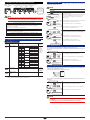
8. SETTING ALARM-RELATED PARAMETERS
8.2 Setting Alarm Output-Related Parameters
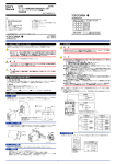
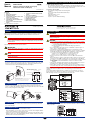
This section describes an example of setting the alarm-1 action (AL1) to “12” (PV low-limit
alarm, with stand-by action), alarm-1 setpoint (A1) to “0” (°C), alarm-1 hysteresis 1 (HY1)
to “5” (°C), alarm ON delay (OND) to “5” (sec.) and alarm OFF delay (OFD) to “5” (sec.)
with the range code No. (IN) set to “62” (instrument input range: -199.9 to 200.0°C).
(Parameters relating to alarm 2 to alarm 4 can be set in the same way as the procedure
below.)
8.1 Setting Ranges and Factory-Set Values of Alarm-Related Parameters
The followings are the factory-set values for the range code No. 61.
They may differ depending on the range code No. specified at the time of order.
Operation Parameter Screen
Parameter
Symbol
Parameter Name
Factory-Set
Value
Setting Range
Alarm-1 setpoint
(A1)
Within the instrument input range.
Operation Parameter Screen
20.0
Alarm-2 setpoint
(A2)
2 points of alarms: 80.0
4 points of alarms: 30.0
Alarm-3 setpoint
(A3)
70.0
Alarm-4 setpoint
(A4)
80.0
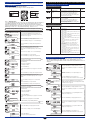
When the power is turned on, the PV screen of the
Operation Parameter Screen appears.
Power ON
Press this key for
more than 3 sec.
Setup Parameter Screen 1
Press
Step 2
Parameter Name
Setting Range
Alarm-1 action
(AL1)
See the Alarm Action Type Codes table.
Alarm-3 action
(AL3)
1
Alarm-4 action
(AL4)
1
The value resulting from adding a hysteresis value
to an alarm setpoint should be within the
instrument input range.
This completes the process for
setting the alarm-1 action.
Press
Alarm-4 Hysteresis
(HY4)
3.0
Setting range: 0 to 999 sec.
Setting resolution: 1 sec.
0
Alarm OFF delay
(OFD)
Setting range: 0 to 999 sec.
Setting resolution: 1 sec.
0
Setpoint
(SP)
Within the instrument input range.
to display "A1." Press the SET/ENT key to display parameter "A1."
Press
or
Press the UP or DOWN key to display a low-limit alarm
value "0.0" (°C) that is set to the DATA display.
The decimal point blinks during
data change.
Press
Press the SET/ENT key to accept low-limit alarm "0.0"
(°C).
.
This completes the process for
setting the alarm-1 setpoint.
Setup Parameter Screen 1
Minimum
value of the
instrument
input range
Press the UP or DOWN key to display "5.0" (°C) on the
DATA display.
Press
or
to display "5.0."
The decimal point blinks during
data change.
<Alarm Action Type Codes>
Press
Alarm Action Type Code
Without Stand-by
Action
Alarm Type
Deenergized
under
Normal
Condition
Alarm Action
With Stand-by
Action
Energized Deunder
energized
Normal under
Condition Normal
Condition
This completes the process for
setting the alarm-1 hysteresis.
Energized
under
Normal
Condition
Press
"OND."
or
to display "5."
Alarm
Press the SET/ENT key to display parameter "OND."
Press the UP or DOWN key to display "5" (sec.) on the
DATA display.
Press
Normal
PV
to display
The decimal point blinks during
data change.
Alarm setpoint
Press
Hysteresis
PV low-limit
alarm
Alarm
PV
.
This completes the process for
setting the alarm ON delay.
Press the SET/ENT key again to display parameter
"OFD."
Normal
Press
Press the SET/ENT key to accept alarm ON delay "5"
(sec).
.
Setting the alarm ON delay
Hysteresis
PV high-limit
alarm
Press the SET/ENT key to accept alarm-1 hysteresis "5.0"
(°C).
.
Setting the hysteresis
Alarm ON delay
(OND)
Press
to display "0.0."
3.0
3.0
for more
than 3 sec.
Then to set the alarm setpoint, press the SET/ENT key for
more than 3 sec. to display the Operation Parameter
Screen. (To set the hysteresis parameter and successive
settings, press the SET/ENT key to display the next
parameter.)
Operation Parameter Screen
3.0
Alarm-3 hysteresis
(HY3)
.
Setting the alarm setpoint
2 points of alarms: 1
4 points of alarms: 2
Alarm-2 hysteresis
(HY2)
Press the SET/ENT key to accept alarm-1 action "12."
Press
2
Alarm-2 action
(AL2)
Alarm-1 hysteresis
(HY1)
The decimal point blinks during
data change.
Factory-Set
Value
Setting the alarm action
Press the UP or DOWN key to display "12" on the DATA
display.
or
to display "12."
Setup Parameter Screen 1
Parameter
Symbol
When the SET/ENT key is pressed for more than 3 sec.
with the Operation Parameter Screen displayed, the Setup
Parameter Screen 1 appears with parameter "AL1"
displayed.
Alarm setpoint
Normal
PV
Alarm
The decimal point blinks during
data change.
Setpoint
Hysteresis
Deviation
low-limit
alarm
Deviation setpoint
Press
This completes the process for
setting the alarm OFF delay.
PV
Press
Normal
Alarm
PV
Press the SET/ENT key for more than 3 sec.
for more
than 3 sec. This causes the Operation Parameter Screen to appear.
To the Operation Parameter Screen
Alarm
9. INPUT ADJUSTMENTS
Deviation setpoint
Hysteresis
Deviation
within high
and low-limit
alarm
Press the SET/ENT key to accept alarm OFF delay "5"
(sec).
.
Normal
Alarm
Deviation setpoint Setpoint
Hysteresis Hysteresis
Deviation
high and
low-limit
alarm
Press the UP or DOWN key to display "5" (sec.) on the
DATA display.
Press
or
to display "5."
Setting the alarm OFF delay
Hysteresis
Deviation
high-limit
alarm
Setpoint
Normal
Alarm
Deviation setpoint
Hysteresis
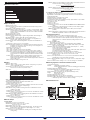
9.1 Setting Ranges and Factory-Set Values of Adjustment-Related Parameters
Setup Parameter Screen 2
Normal
PV
Deviation setpoint
Setpoint
Parameter
Symbol
Deviation setpoint
No alarm
(Parameters A1 to A4 are not displayed.)
Stand-by Action
Normal
Abnormal
(Alarm ON)
Power ON
Low-limit
alarm
setpoint
Factory-Set
Value
OFF (0) or ON (1)
(This parameter is used (set to ON) to reset adjusted values.)
OFF
Input adjustment point
⫾10% of the instrument input range span (and BL < BH)
Minimum value of
the instrument
input range
⫾10% of the instrument input range span (and AL < AH)
Minimum value of
the instrument
input range
Input adjustment
LOW (AL)
If an alarm type code with
stand-by action is set, alarm
action is turned off during the
start-up control.
This function is useful at power
ON or when changing the alarm
type.
Setting Range
Input adjustment reset
(RST)
LOW (BL)
PV
Regarded
as normal
Parameter Name
value of
Input adjustment point ⫾10% of the instrument input range span (and BL < BH) Maximum
the instrument
HIGH (BH)
Input adjustment
HIGH (AH)
input range
⫾10% of the instrument input range span (and AL < AH)
Maximum value of
the instrument
input range
Time
4
IM 77J04R31-01E 1st Edition : 2006.08.31-00