1
When the input range corresponding to the output scaling converted into resistance is
less than 130 Ω in the instrument input range H:
14. MAIN SPECIFICATIONS
■ Model and Suffix Codes
Accuracy=
Model
MVRK
Type
Suffix Codes
-0 0
-
/
-0
0
3
6
Power Supply
-U
-Z
Input Signal
1
2
Output Signal
6
A
P
N
Monitor Output
U
D
N
Burnout
Optional Specification
/SN
Description
Digital Limit Alarm (RTD Input Type)
General use type
Always 0
24 V DC±10%
100-240 V AC/DC (Operating range: 85 to 264 V AC/DC)
RTD input
Custom order
Alarm output (transfer contact [1a1b] ), 2 points
Alarm output (NO contact), 4 points
1 to 5 V DC
4 to 20 mA DC
Communication function (RS-485)
No monitor output
UP
DOWN
OFF (No burnout)
Without socket
±0.1 (%) ⫻ 130 (Ω)
(%)
Input range converted into resistance (Ω)
When the input range corresponding to the output scaling converted into resistance is
less than 38.6 Ω in the instrument input range M :
Accuracy=
±0.1 (%) ⫻ 38.6 (Ω)
(%)
Input range converted into resistance (Ω)
● Communication Output (RS-485)
The MVRK can be connected to a personal computer, graphic panel, Yokogawa’s
programmable controller FA-M3 or programmable controllers of other manufacturers.
Standards: EIA RS-485
Maximum number of connectable units: 31 units
Maximum communication distance: 1200 m
Communication method: 2-wire half duplex, start-stop synchronization, non-procedural
Baud rate: 1200, 2400, 4800 or 9600 bps
Data length: 8 or 7 bits
Stop bit: 1 or 2 bits
Parity: Even, odd or none
Communication protocol: PC link, PC link with SUM, MODBUS ASCII, MODBUS RTU or
Ladder
PC link communication: Communication protocol with a personal computer, graphic
panel or UT link module of FA-M3
MODBUS communication: Communication protocol with a personal computer
(SCADA).
Ladder communication: Communication protocol with ladder communication module of
FA-M3 and programmable controller of other manufacturers.
■ Input and Display
Number of inputs: 1 point
Input signal: Set the measured input range within the instrument input range. (Refer to
Section 7.1.)
Input resistance: 1 MΩ (4 kΩ during power off)
Allowable leadwire resistance: [Input span (°C ) ⫻ 0.4 (Ω)] or 10 Ω per leadwire, equal or
less than whichever is smaller. (Make the resistance of each wire the same.)
However, when used with BARD-700, this value can be added to the BARD
internal resistance.
Detective current: Approx. 0.5 mA
Maximum allowable input: ±4 V DC
PV (measured value) display: 4-digit, 7-segment, red/green LED, character height of
13.5 mm
Data display: 4-digit, 7-segment, green LED, character height of 9 mm
Alarm indicator lamp: 2 orange LEDs for 2 points of alarms or 4 orange LEDs for 4
points of alarms. Lights up if an alarm occurs.
Economical mode: Turns off the indicating LED if no keystroke is made within the set
time.
Setting range: 0 (does not go off) or 1 to 60 minutes
Active color PV display (PV display color changing function): This function changes the
PV display color from green to red or from red to green according to the set
PV display color mode shown below.
[PV display color mode to be set]
Link to alarm 1: Links to alarm 1.
Link to alarm 1 and alarm 2: Links to alarm 1 and alarm 2.
Link to alarm 1 to alarm 4 (only for 4 points of alarms): Links to alarm 1 to alarm 4.
SP deviation: Changes the PV display color according to whether measured value is
less than SP deviation high limit or SP deviation high limit or more; whether
measured value is more than SP deviation low limit or SP deviation low limit
or less.
PV limit: Changes the PV display color according to whether measured value is less
than measured range high limit or measured range high limit or more;
whether measured value is more than measured range low limit or measured
range low limit or less.
Fixed color: Fixes PV display color in green or red.
■ Standard Performance
Input display accuracy: ±0.1%±1 digit of instrument input range span
Alarm action point setting accuracy: ±0.1%±1 digit of instrument input range span
Response speed: 500 ms (Time to alarm output when the input change is 10 to 90% and
alarm setpoint is 50%. When the alarm delay setting and hysteresis are
minimum.)
Burnout: UP, DOWN or OFF
Burnout time: 60 seconds or less
Action: High-limit alarm output for UP, Low-limit alarm output for DOWN
Insulation resistance: 100 MΩ/500 V DC between inputs, alarm outputs, power supply
and monitor output mutually.
Withstand voltage: 2000 V AC/minute between inputs, (alarm outputs 1, 2, 3 and 4),
monitor output and power supply mutually.
However, the following is excluded.
1000 V AC/minute between (alarm outputs 1 and 4) and (alarm outputs 2 and
3) and between inputs and monitor output.
(For 2 points of alarms, alarm outputs 3 and 4 are excluded.)
Power supply voltage: 24 V DC±10%, 100-240 V AC/DC (-15%, +10%) 50/60Hz
Power consumption: 24 V DC 2.7 W, 110 V DC 2.5 W, 100 V AC 4.2 VA,
200 V AC 5.4 VA
Effect of power supply fluctuation: ±0.1% of span or less for the fluctuations within the
allowable range of each power supply specification
Effect of ambient temperature change: ±0.2% of span or less for a temperature change
of 10°C
Effect of leadwire resistance change: ±0.2°C or less for a change of 10 Ω/leadwire
■ Output
■ Mounting, Appearance and Environmental Conditions
Signal type: Relay contact
Number of outputs: 2 points of contact outputs (transfer contact [1a1b] ) or 4 points of
contact outputs (NO contact)
Contact rating: 120 V AC/1 A, 220 V AC/0.5 A (resistance load)
30 V DC/1 A, 120 V DC/0.1 A (resistance load)
Alarm action:
Relay action
PV low-limit alarm
Energized or de-energized under normal condition
Deviation high-limit alarm
Energized or de-energized under normal condition
Deviation low-limit alarm
Energized or de-energized under normal condition
Deviation high and low-limit alarm
De-energized under normal condition
Deviation within high and low-limit alarm De-energized under normal condition
Alarm setting range: Within the input range
Setting resolution: 1 digit (0.1°C)
Setpoint setting: Virtual setpoint when the deviation alarm occurs
Setting range: Within the input range
Setting resolution: 1 digit (0.1°C)
Hysteresis setting range: The value resulting from adding a hysteresis value to an alarm
setpoint should be within the set input range.
Setting resolution: 1 digit (0.1°C)
Alarm ON delay setting: Condition monitoring time from the establishment of alarm
conditions to its output
Setting range: 0 to 999 seconds
Setting resolution: 1 second (However, about 0.2 second is to be added to the set time
to prevent wrong operation.)
Alarm OFF delay setting: Condition monitoring time from the establishment of return-tonormal conditions to its output
Setting range: 0 to 999 seconds
Setting resolution: 1 second (However, about 0.2 second is to be added to the set time
to prevent wrong operation.)
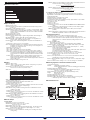
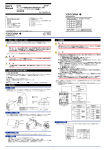
■ External Dimensions
Unit: mm
Main unit
Socket
40
86.5
80
2-Ø4.5
Mounting hole
(depth: 24.5)
85
Energized or de-energized under normal condition
81
PV high-limit alarm
35.4
Alarm action
Construction: Plug-in type
Material:
Casing; ABS resin (black), UL94 V-0
Socket; Modified polyphenylene oxide resin, including glass fiber (black),
UL94-V1
Mounting method: Wall or DIN rail mounting
Connection method: M3.5 screw terminal for input/output and power supply
3-pin 2-piece connector for monitor output
External dimensions: 51 (W)⫻86.5 (H)⫻133 (D) mm (including a socket)
Weight:
Main unit; approx. 270 g
Socket; approx. 80 g
Operating temperature range: 0 to 50°C
Operating humidity range: 5 to 90% RH (no condensation)
Operating conditions: Avoid installation in such environments as corrosive gas like
sulfide hydrogen, dust, sea breeze and direct sunlight.
DIN rail
Monitor output
terminal *1
50
103
10
133
30
11-M3.5⫻7
screw
3.3
7.8
51 max.
*1 To be added when the monitor output is specified.
■ Monitor Output
● Analog Output
Output signal: 1 to 5 V DC or 4 to 20 mA DC
Allowable load resistance: 2 kΩ or more for 1 to 5 V DC
350 Ω or less for 4 to 20 mA DC
Output variable range: -6 to +106%
Output scaling: Set any value within the measured input range. (Set the value so that
the input range corresponding to the output scaling is 10°C or more.)
Output accuracy: ±0.1% of output span
However, the accuracy is limited in the following cases according to the output
scaling setting.
8
IM 77J04R31-01E 1st Edition : 2006.08.31-00