1
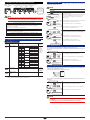
10. SETTING ACTIVE COLOR PV DISPLAY (PV DISPLAY COLOR CHANGING FUNCTION)
9.2 Instrument for Adjustments
• 6-dial variable resistor (Yokogawa Meters & Instruments’ 2793 01 or equivalent): 1
10.1 Setting Ranges and Factory-Set Values
9.3 Input Adjustment
Setup Parameter Screen 1
9.3.1
Connecting the Adjustment Instrument
Connect the input and supply voltage as shown in the figure below.
8
Power supply
7 L+
7
6
5
4
(SUPPLY)
8 N–
9
10 11
3
1
Parameter
Symbol
Input signal
6-dial
variable
resistor
A
4
B
5
B
6
2
9.3.2
Adjusting Inputs
Carry out input adjustments between two points, or the minimum value (BL: input adjustment
point LOW) and maximum value (BH: input adjustment point HIGH) that have been set
within the adjustment range (see Section 9.1). This subsection describes an example of
making an input adjustment between two points within the range of -50.0 to 150.0°C with the
MVRK range code No. set to “62” (instrument input range: -199.9 to 200.0°C).
Parameter
Symbol
Operation Parameter Screen
When you press the SET/ENT key for more than 3 sec.
with the Operation Parameter Screen displayed, the Setup
Parameter Screen 1 appears.
Setup Parameter Screen 1
Press
Press
Press the SET/ENT key to display parameter "LOC."
to display
"LOC."
to display
"-1."
Press the DOWN key to display "-1" on the DATA display.
The decimal point blinks during
data change.
Press
Press the SET/ENT key to display the Setup Parameter
Screen 2.
.
Setup Parameter Screen 2
Press
Press
Press the SET/ENT key to display parameter "BL."
to
display "BL." In this case, the DATA display shows "-199.9," the
minimum value of instrument input range of the set range
code No.
to display
"-50.0." Press the UP key to display "-50.0" on the DATA display.
The decimal point blinks during
data change.
Press
.
Press
.
Low limit for PV
display color change
(PCL)
When PV display color mode (PCM) is 6 or 7:
-1999 to PCH-1digit
When PV display color mode (PCM) is 8 or 9:
-100.0 to 100.0% of the measured input range
* The setting range depends on the setting of the
decimal point position (SDP).
⫺
⫺
Parameter Name
Factory-Set
Value
Setting Range
1
*: PV display color is changed linking to the setting range of high limit (PCH) and low limit (PCL) for PV display color change.
Press the SET/ENT key to accept this data.
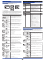
10.2 Setting Active Color PV Display
Using the 6-dial variable resistor, apply resistance equivalent
to the input -50°C to the MVRK.
or
This section describes an example of setting the PV display color mode (PCM) to “6,”
high limit for PV display color change (PCH) to “70.0” and low limit (PCL) to “20.0.”
The procedure below begins with the condition in which the Setup Parameter Screen 2 is
displayed.
This causes parameter "AL" and the measured value to
appear alternately.
Press the UP or DOWN key.
The decimal point blinks.
.
Setup Parameter Screen 2
Press
.
to display
"PCM."
Press the SET/ENT key.
"-52.2" appears on the
DATA display.
or
Press
to display "6."
" The decimal point blinks during
The value before adjustment (-52.2) appears on the DATA
display.
Press the SET/ENT key to display parameter "PCM."
Press the UP or DOWN key to display "6" on the DATA
display.
data change.
Press
.
Press
Press the SET/ENT key to display the next parameter "BH."
to display
"150.0."
The decimal point blinks during
data change.
Press
.
Press
.
Press
for more
Press the SET/ENT key for more than 3 sec.
than 3 sec. This causes the Operation Parameter Screen to appear.
Operation Parameter Screen
Press the DOWN key to display "150.0" on the DATA
display.
Press this key for
more than 3 sec.
Press the SET/ENT key to accept this data.
Setup Parameter Screen 1
Using the 6-dial variable resistor, apply resistance equivalent
to the input 150°C to the MVRK.
.
Press
or
to display "70.0."
Press the SET/ENT key.
Press
This completes the input adjustment for the MVRK.
If additional re-adjustment must be made, take the following steps and then perform the
procedure above.
Press
Press
to display
"RST."
to display
"ON."
.
The previously adjusted value
will be reset.
.
to display
"PCL."
Press
or
to display "20.0."
Press the SET/ENT key to accept the high limit for PV
display color change "70.0."
Press the SET/ENT key to display parameter "PCL."
Press the UP or DOWN key to display "20.0" on the DATA
display.
The decimal point blinks during
data change.
Press the SET/ENT key to display parameter "RST."
Press
.
This completes the process for
setting the low limit for PV display
color change.
Press the UP key to display "ON" on the DATA display.
Press
The decimal point blinks during
data change.
Press
Press the UP or DOWN key to display "70.0" on the DATA
display.
This completes the process for
setting the high limit for PV display
color change.
The value before adjustment (153.9) appears on the DATA
display.
This completes the input
adjustment.
Press the SET/ENT key to display parameter "PCH."
The decimal point blinks during
data change.
Press the UP or DOWN key.
The decimal point blinks.
Press
.
to display
"PCH."
Press the SET/ENT key.
This resets the previously adjusted value.
Press the SET/ENT key to accept the low limit for PV
display color change "20.0."
Setting the high and low limits for PV display color change
or
Press
This causes parameter "AH" and the measured value to
appear alternately.
The decimal point blinks.
Press
When you press the SET/ENT key for more than 3 sec.
with the Operation Parameter Screen displayed, the Setup
Parameter Screen 1 appears.
Press the SET/ENT key to display the next parameter.
The measured value and
parameter AH are displayed
alternately.
Press
Press the SET/ENT key to accept PV display color
mode "6."
This completes the process for
setting the PV display color mode.
In this case, the DATA display shows "200.0," the
maximum value of instrument input range of the set range
code No.
Press
.
Setting the PV display color mode
The decimal point blinks.
Press
When PV display color mode (PCM) is 6 or 7:
PCL+1digit to 9999
When PV display color mode (PCM) is 8 or 9:
-100.0 to 100.0% of the measured input range
* The setting range depends on the setting of the
decimal point position (SDP).
Press the SET/ENT key to display the next parameter.
The measured value and
parameter AL are
displayed alternately.
Press
High limit for PV
display color change
(PCH)
PV display color mode 0: Fixed in green
(PCM)
1: Fixed in red
2: Link to alarm 1
(under normal condition: green; at alarm status: red)
3: Link to alarm 1
(under normal condition: red; at alarm status: green)
4: Link to alarm 1 and alarm 2
(under normal condition: green; at alarm status: red)
5: Link to alarm 1 and alarm 2
(under normal condition: red; at alarm status: green)
6: PV limit*
(when more than PCL, less than PCH: green;
when PCL or less, PCH or more: red)
7: PV limit*
(when more than PCL, less than PCH:red;
when PCL or less, PCH or more: green)
8: SP deviation*
(when more than SP-PCL, less than SP+PCH: green;
when SP-PCL or less, SP+PCH or more: red)
9: SP deviation*
(when more than SP-PCL, less than SP+PCH: red;
when SP-PCL or less, SP+PCH or more: green)
10: Link to alarm 1 to alarm 4
(under normal condition: green; at alarm status: red)
11: Link to alarm 1 to alarm 4
(under normal condition: red; at alarm status: green)
When the power is turned on, the PV screen of the
Operation Parameter Screen appears.
Press this key for
more than 3 sec.
Factory-Set
Value
Setting Range
Setup Parameter Screen 2
The MVRK enters the operable status as soon as the power is turned on, but requires 10 to 15 minutes
of warm-up to meet the performance requirements.
Power ON
Parameter Name
Press the SET/ENT key for more than 3 sec.
for more
than 3 sec. This causes the Operation Parameter Screen to appear.
To the Operation Parameter Screen
5
IM 77J04R31-01E 1st Edition : 2006.08.31-00