1
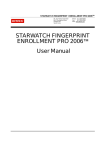
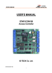
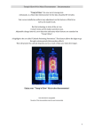
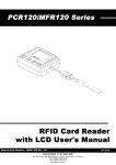
Quick Installation Guide
Proximity & PIN
Time & Attendance Access Controller
※ 505R/IP505R/SR505 QUICK INSTALLATION GUIDE
1. IMPORTANT SAFETY INSTRUCTIONS
The description below is to keep user‟s safety and prevent any product damage. Please fully read these instruction
and use the product properly.
Danger: This symbol indicates that incorrect handling of the product may result in serious injury or
death.
Warning: This symbol indicates that incorrect handling of the product may result in injury or
property damage.
Cautions about power
- Only use the standard voltage (DC +12V/ 350mA).
- If the product emits smoke or smells, stop using the product. Unplug the product from DC power source and
contact nearest service center.
Cautions about installation
- Do not install the product in humid, dust (metallic dust) and sooty place.
- Do not install the product in a place subject to high or low temperature and high humidity
- Do not install the product with tools such as driver in hand when power has been supplied.
Cautions about usage
- Do not drop liquid like water and give a shock severely.
- Do not place magnetic objects near the product.
- Do not replace the wiring cables installed by experts.
- Do not use the product near direct sunlight and heating apparatus.
- If you want to relocate the installed product, turn power off and then move and reinstall it.
- Do not use the product near flammable spray or objects.
- Do not disassemble, repair or modify the product by yourself. If the product needs service or repair, contact
nearest service center.
- If liquid has been spilled on the product, unplug it and contact nearest service center.
Cautions about cleaning
- Do not clean the product with water. Clean gently with dry cloth or towel.
- Do not use chemicals such as benzene, thinner or acetone for cleaning.
2
※ 505R/IP505R/SR505 QUICK INSTALLATION GUIDE
2. WHAT’S INCLUDED
Please unpack and check the contents of the box. If any of these parts are missing, please contact a nearby distributor
or IDTECK.
Main Unit
Wall Mount
O-ring
User’s Manual
(1ea)
(1ea)
(5ea)
(1ea)
Screws
3.5 x 12 mm (4ea)
3.5 x 40 mm (4ea)
Anchor bolt 6 x 30 mm (4ea)
Cable / Diode
300mm 2P
300mm 3P
300mm 4P
300mm 7P
300mm 10P
UF4004 DIP
3
(1ea)
(1ea)
(1ea)
(1ea)
(1ea)
(2ea)
※ 505R/IP505R/SR505 QUICK INSTALLATION GUIDE
3. PARTS CODE AND DESCRIPTION
3.1 Front Panel
1 LCD Display
○
5 Card Reading
○
Status LED
2 3LEDs
○
3 16 Keypad
○
4 Function Key
○
Figure: Star 505R Front Panel
1 LCD Display:
○
LCD displays Star 505R‟s status.
2 3LEDs:
○
When the power is supplied to Star 505R, the red LED is turned on.
When the Relay #1 is operated, the green LED is turned on.
When the Relay #2 is operated, the yellow LED is turned on.
3 16 Keypad:
○
You can operate Star 505R manually by using the keypad.
4 Function Key:
○
The Star 505R has four Function keys: [F1], [F2], [F3], [F4]
5 Card Reading Status LED:
○
When a card is read, the card reading status LED turns on green.
4
※ 505R/IP505R/SR505 QUICK INSTALLATION GUIDE
3.2 The Back of Panel
1 Initialization Switch
○
Button
3 Tamper Switch
○
2 Communication Display LED
○
Figure: Star 505R Rear Panel
1 Initialization Switch
○
This switch is used to initialize Star 505R. For initialization, press down this switch and then keep it more than 2
seconds. Refer to „8.2 System Initialization‟ of the main manual for more details.
2 Communication Display LED
○
# 3, 4(yellow, green) LED will twinkle during RS232, RS422 and TCP/IP communication.
If the LAN is connected normally during TCP/IP communication, green LED will turn on. But in the
collision status, the #2 LED (red) turns on.
1 2
3
4
Figure: Magnification of the Communication Display LED in the Rear Panel
3 Tamper Switch
○
If someone takes off installed Star 505R on the wall by force, this tamper switch is activated then buzzer makes
sound.
5
※ 505R/IP505R/SR505 QUICK INSTALLATION GUIDE
3.3 Connection and Color Code Table
CON6
CON4
CON3
CON2
CON5
CON7
IO PORT NAME
POWER
Main Power(+12V)
Power Ground
OUTPUT
Door Relay(COM)
Door Relay(NC)
Door Relay(NO)
Alarm Relay(COM)
Alarm Relay(NC)
Alarm Relay(NO)
INPUT
Exit Button
Door Sensor
Aux Input 1
Aux Input 2
EXTRA READER PORT
Wiegand Data0
Wiegand Data1
OUTPUT
TTL Output1
TTL Output2
OK Signal Out
Error Signal Out
Tamper Switch Out
RS232 INTERFACE
RS232-TX
RS232-RX
Ground
RS422 INTERFACE
RS422-TX(-)
RS422-TX(+)
RS422-RX(-)
RS422-RX(+)
TCP/IP Communication
SIGNAL NAME
CON7
DC +12V
GND
CON4
COM(1)
NC(1)
NO(1)
COM(2)
NC(2)
NO(2)
CON4
EXIT
CONTACT
IN1
IN2
CON5
DATA0
DATA1
CON5
TTL1/ Weigand D0 Out
TTL2/ Weigand D1 Out
Not use
Not use
Tamper Switch Out
CON2
TXD
RXD
GND
CON3
TX(-)
TX(+)
RX(-)
RX(+)
CON6
TCP/IP Communication
6
COLOR CODED
Red
Black
Gray with Red Stripe
Blue with White Stripe
White with Red Stripe
White
Purple with White Stripe
Purple
Orange
Yellow with Red Stripe
Green
Green with White Stripe
Pink
Cyan
Orange with White Stripe
Brown with White Stripe
Green with Red Stripe
Blue with Red Stripe
Yellow with White Stripe
Black with White Stripe
Read with White Stripe
Black
Yellow
Gray
Blue
Brown
8PIN Connecter Module
※ 505R/IP505R/SR505 QUICK INSTALLATION GUIDE
3.4 TCP/IP Module (Optional)
Optional TCP/IP Module is required to use TCP/IP communication
4. INSTALLATION CHECKPOINTS & TIPS
4.1 CHECK POINTS BEFORE INSTALLATION
4.1.1 Installation Layout
Door Lock
Door Lock
Exit Button
Exit Button
Figure: System Installation Layout
4.1.2 Recommended Cable Type and Permissible Length of Cable
Reference
Description
Cable Specification
Maximum
Distance
①
Star 505R Power (DC12V)
DC Power -> Star 505R
Belden #9409, 18 AWG
2 conductor, unshielded
30m
②*
Reader (Power and Data)
Extra Reader -> Star 505R
③
Door Contact
Exit Button
Belden #9512, 22 AWG
4 conductor, shielded
Belden #9514, 22 AWG
8 conductor, shielded
Belden #9512, 22 AWG
4 conductor, shielded
7
150m
300m
※ 505R/IP505R/SR505 QUICK INSTALLATION GUIDE
Sensor Input
Belden #9514, 22 AWG
Input -> Star 505R
8 conductor, shielded
Door Lock, Alarm Device
Belden #9409, 18AWG
300m
④
Lock (Alarm) -> Star 505R
2 conductor, unshielded
RS232 Cable
Belden #9829, 24 AWG
15m
⑤
Converter -> Host P.C.
2-twisted pair, shielded
RS485 Cable
Belden #9829, 24 AWG
Star 505R -> Star 505R
2-twisted pair, shielded
Star 505R -> Converter
1,200m
⑥
RS422 Cable
Belden #9830, 24 AWG
Star 505R -> Star 505R
3-twisted pair, shielded
Star 505R -> Converter
* Requires thicker wire if you connect the reader with high current consumption.
4.2 CHECK POINTS DURING INSTALLATION
4.2.1 Termination Resistor
Termination resistors are used to match impedance of the network to the impedance of the transmission line being
used. When impedance is mismatched, the transmitted signal is not completely absorbed by the receiver and a portion
of signal is reflected back into the transmission line.
A 120Ω resistor can be used for termination resistor in parallel between the receiver lines “A” and “B” for 2 wires
RS485 system or “RX+” and “RX-” for 4 wires RS422 system. A termination resistor of less than 90Ω should not be
used and no more than 2 terminations should be used in one networking system.
4.2.2 How to Connect Termination Resistors
Figure: Termination Resistors for 2 Wire RS485 Communication System
RS422/RS232
Figure: Termination Resistors for 4 Wire RS422 Communication System
4.2.3 Grounding System for Communication Cable
We recommend to using proper grounding system on the communication cable. The best method for grounding
system is to put the shield wire of the communication cable to the 1st class earth grounding; however it is not so easy
to bring the earth ground to the communication cable and also the installation cost is raised.
There will be three grounding points where you can find during installation;
1) Earth Ground
2) Chassis Ground
3) Power Ground
8
※ 505R/IP505R/SR505 QUICK INSTALLATION GUIDE
The most important point for grounding system is not to connect both ends of shield wires to the grounding system; in
this case there will be a current flow through the shield wire when the voltage level of both ends of shield wire is not
equal and this current flow will create noise and interfere to communications.
For the good grounding, we recommend connecting ONLY one end of shield wire of communication cable to the
grounding system; If you find earth ground nearby, then connect one end of shield wire to earth ground; If you do not
have earth ground nearby, then find chassis ground and connect one end of shield wire to chassis ground; If you do
not find both earth ground and chassis ground, then connect one end of shield wire to power ground. (GND of Star
505R)
Note that if the chassis ground is not properly connected to the earth and floated from the ground level, then grounding
to the chassis ground will give the worst communication; in this case we recommend to using power ground instead of
chassis ground.
Figure: Grounding System
4.2.4 Reverse Diode Connection
If you connect an inductor (Door Locks or Alarm device) to the output relays, there will be a high surge voltage created
while the inductor is turning on and off. If you do not connect reverse diode, the surge voltage will transfer and damage
to the electronic circuit of the controller. It is strongly recommended to add a reverse diode between the inductor coils
to absorb this surge voltage.
Figure: Reverse Diode Connection
5. INSTALLATION
5.1 Wall Mount Installation
Real size template is on back of this manual. Tear off the template page and attach it to the wall. And then follow steps
below to install the Star 505R. (You can install the Star 505R directly, if the gang box is installed on the wall.)
1. Position the Wall Mount template to the location at which you want to install the unit and mark 2 drilling (two Tap #632 holes) positions and then drill it
9
※ 505R/IP505R/SR505 QUICK INSTALLATION GUIDE
2. Drill a 1/2” hole on the center of the wall mount.
3. Using two screws, install the wall mount to the hall.
4. Take out the cable through the center hole.
5. After connecting cables, initialize the Star 505R. And then test basic function. (Refer to „8.2 SYSTEM
INITIALIZATION‟ of the main manual)
6. Insert O-ring at 5 positions and then insert the bundle of cable to the center hole.
7. Put the Star 505R unit on the wall mount and push it until it is fixed up.
※ CAUTION
Before mounting the Star 505R unit to the Wall Mount bracket, operational test of the unit should be
completed, as the locking pins will lock the unit to the Wall Mount. Removing the unit from the Wall Mount
bracket after they have been installed together may cause damages to the bracket and render its effectiveness.
Insert 5 O-rings to the wall mount as indicated, then route the cable of the main unit through the center hole
and push the main unit to wall mount to lock the main unit and make sure that the main unit is locked with
wall mount.
10
※ 505R/IP505R/SR505 QUICK INSTALLATION GUIDE
5.2 SYSTEM INITIALIZATION
You have to initialize the Star 505R unit prior to installation.
Once power is supplied to the Star 505R, press down the initialization switch on the back of the Star 505R unit and
then keep it more than 2 seconds, then you can see displays below on the LCD. If you want initialization, press key
<1> otherwise press key <0>.
SYSTEM INIT.
1 – YES, 0 - NO
WAITING !!!
2
○
1
○
INIT. OK !!!
3
○
○
1 Press the key <1> if you wish to initialize the Star 505R.
○
2 Initialization is processing
○
3 Rebooted automatically after Initialization
Initialization Switch
Figure: The Position of Initialization Switch
11
※ 505R/IP505R/SR505 QUICK INSTALLATION GUIDE
5.3 WIRING
5.3.1 Power
Connect (+) wire of DC +12V power to the DC +12V (Red wire) of Star 505R.
Connect GND (-) wire of DC +12V power to the GND (Black wire) of Star 505R.
5.3.2 Input Connection
Exit Button Connection
- Connect one wire from an Exit Button to the Orange wire.
- Connect the other wire from the Exit Button to the GND.
Door Contact Sensor Connection
- Connect one wire (COM) from a Door Contact Sensor to the Yellow wire with Red stripe.
- Connect the other wire (NC) from the Door Contact Sensor to GND.
Auxiliary Input Connection
(Applied to Aux Input IN1, Aux Input IN2)
- Connect one wire from an Auxiliary Input Device to one of the Input IN1, IN2.
- Connect the other wire from the Auxiliary Input Device to GND.
Figure: Input Devices Connection
12
※ 505R/IP505R/SR505 QUICK INSTALLATION GUIDE
2.2K Resistance Connection for Cut Off Check
You have to connect a 2.2K Resistor between the input wire (e.g. Orange wire) and the GND to apply the Cut Off
Check feature.
First, select whether or not to check the Cut Off status of each device from “F2 SETUP MENU” -> “5. IN/OUT
DEFINE”-> “21.CUT OFF CHECK”.
Second, set the desired output that will be generated in the event of a cut off from “F2 SETUP MENU” -> “5. IN/OUT
DEFINE”-> 18. CUT OFF ALARM”.
Figure: 2.2 K Resistance Connections for Cut Off Check
5.3.3 Output Connections
Door Lock (Power Fail Safe) Connection (Relay 1)
- Connect COM port of Relay 1(Gray with Red Stripe) to + 12V (Red wire)
- Connect NC port of Relay 1(Blue with White Stripe) to (+) wire of Door Lock Device.
- Connect GND (Black wire) port to (-) wire of Door Lock Devices.
Door Lock (Power Fail Secure) Connection (Relay 1)
- Connect COM port of Relay 1(Gray with Red Stripe) to + 12V (Red wire)
- Connect NO port of Relay 1(White with Red Stripe) to (+) wire of Door Lock Device
- Connect GND (Black wire) port to (-) wire of Door Lock Devices
Alarm Device Connection (Relay 2)
- Connect COM port of Relay 2 (White) to + 12V (Red wire)
- Connect NO port of Relay 2 (Purple) to (+) wire of Alarm Devices.
- Connect GND (Black wire) port to (-) wire of Alarm Devices
Figure: Door Lock / Alarm Device Connection
CAUTION: Please add one diode as shown above. A fast recovery diode (Current: Min. 1A), 1N4001 - 1N4007
or similar, is recommended.
Wiegand Data Connection (Applicable to Reader Mode)
13
※ 505R/IP505R/SR505 QUICK INSTALLATION GUIDE
-Connect DATA0 IN wire of controller to TTL1/D0 (TTL Output) wire of 505R (Orange with White Stripe)
-Connect DATA1 IN wire of controller to TTL2/D1 (TTL Output2) wire of 505R (Brown with White Stripe)
CAUTION: If the controller and 505R use separate power sources, you must connect the GND between the controller
and 505R
5.3.4 Extra Reader Connections
Proximity Reader Connection
1. Connect (+) wire of the Proximity Reader to DC +12V (Red wire).
2. Connect (-) wire of the Proximity Reader to GND of Power (Black wire).
3. Connect Data-0 wire of the Proximity Reader to D0, the Pink wire.
4. Connect Data-1 wire of the Proximity Reader to D1, the Cyan wire.
CAUTION: If the Extra Reader and 505R use separate power sources, you must connect the GND between the
controller and 505R
Compatible Readers:
Star 505R/IP505R:
Standard 26bit Wiegand Format Proximity Readers.
Standard 26bit Wiegand+8bit Burst Format Proximity and Keypad Readers.
SR505:
Standard 34bitWiegand Format Proximity Readers.
Standard 34bitWiegand+8bit Burst Format Proximity and Keypad Readers.
Recommended Readers:
Star 505R/IP505R:
RF-TINY, RF10, RF20, RF30, RFK101, FGR006, FGR006EX, iP10, iP20, iP30, iPK101.
SR505:
SR10, SR20, SR30, SRK101, FGR006SR, FGR006SRB.
Figure: Star 505R/Reader Connection
14
※ 505R/IP505R/SR505 QUICK INSTALLATION GUIDE
6. COMMUNICATION
6.1 RS232 Communication Port Connection
A 9-PIN connector is required to connect the Star 505R to the PC via RS232 communication.
Please follow the instructions below:
- Connect RS232-TX (Black wire with White stripe) port of Star 505R to the PIN 2 of the 9-PIN connector.
- Connect RS232-RX (Red wire with White stripe) port of Star 505R to the PIN 3 of the 9-PIN connector.
- Connect GND of Star 505R to the PIN 5 of the 9-PIN connector.
- Plug in the 9-PIN connector to COM1 or COM2 port of the PC.
- Install and run Star 505R Application Software.
6.2 RS422 Communication Port Connection
6.2.1 RS422 Connection (Single connection of Star 505R)
An RS422/RS232 converter (INC400) is required to use RS422 communication between the Star 505R and the PC.
Please follow the instructions below:
- Connect RS422-TX (+) (Gray wire) of Star 505R to RS422-RX (+) port of converter.
- Connect RS422-TX (-) (Yellow wire) of Star 505R to RS422-RX (-) port of converter.
- Connect RS422-RX (+) (Brown wire) of Star 505R to RS422-TX (+) port of converter.
- Connect RS422-RX (-) (Blue wire) of Star 505R to RS422-TX (-) port of converter.
- Plug in the RS232 9PIN connector of the converter to the COM1 or COM2 port of the PC.
- Install and run Star 505R Application Software.
Figure: Single connection of Star 505R
6.2.2 RS422 Connection (Multiple Connection of Star 505Rs)
RS422/RS232 converter is required to use RS422 communication between multiple Star 505Rs and the PC. Please
follow the following instructions.
First, you have to connect all RS422 port of all Star 505Rs in parallel.
15
※ 505R/IP505R/SR505 QUICK INSTALLATION GUIDE
- Connect RS422-TX (+) of one Star 505R to RS422-TX (+) of another Star 505R.
- Connect RS422-TX (-) of one Star 505R to RS422-TX (-) of another Star 505R.
- Connect RS422-RX (+) of one Star 505R to RS422-RX (+) of another Star 505R.
- Connect RS422-RX (-) of one Star 505R to RS422-RX (-) of another Star 505R.
Second, you have to connect one of RS422 port of Star 505R to RS422/RS232 converter.
- Connect RS422-TX (+) of the one Star 505R to RX (+) port of the converter.
- Connect RS422-TX (-) of the one Star 505R to RX (-) port of the converter.
- Connect RS422-RX (+) of the one Star 505R to TX (+) port of the converter.
- Connect RS422-RX (-) of the one Star 505R to TX (-) port of the converter.
- Plug in the RS232 9PIN connector of the converter to the COM1 or COM2 port of the PC.
- Install and run Star 505R Application Software
Figure: Multiple connections of Star 505Rs
6.3 TCP/IP Communication Port Connection (optional)
Optional TCP/IP module is required to use TCP/IP communication between the Star 505R and the PC. Please follow
the following instructions below:
1. Connect the LAN cable of the network system to the RJ45 jack of the Star 505R.
2. Set the ID of the Star 505R.
3. Install and run the Star 505R Application Software.
Figure: TCP/IP Connection with Star 505R Device and PC
16
※ 505R/IP505R/SR505 QUICK INSTALLATION GUIDE
6.4 TCP/IP Converter (External converter)
When you use the TCP/IP converter, choose only one converter between RS232 and RS422.
Figure: TCP/IP Converter between Star 505R Device and PC
INTERFACE
RS232
RS422
STAR 505R
TX (CON2)
RX (CON2)
GND(CON2)
TX+ (CON3)
TX- (CON3)
RX+ (CON3)
RX- (CON3)
ILAN422
RX (RS232 DSUB9)
TX (RS232 DSUB9)
GND
RX+ (RS422 CONNECTOR)
RX- (RS422 CONNECTOR)
TX+ (RS422 CONNECTOR)
TX- (RS422 CONNECTOR)
LINE COLOR
BLACK+WHITE
RED + WHITE
BLACK
GRAY
YELLOW
BROWN
BLUE
7. INITIAL SETUP
7.1 system Initialization
Press and hold the initialization button.
Apply DC +12V power to the Star 505R. Release the button when the LCD displays “Initialize OK?”
After installation and cable connections are completed, apply power (DC12V) to the Star 505R with the initialization
button held down. (The initialization button can be found on the back of the Star 505R.) Then, the LCD will first display
“Initialize OK? 1: Yes 0: No”. Press <1> key if you want to initialize the system or <0> to cancel the initialization
procedure. After all the initialization process is completed, the system will be operating in the normal mode and the
LCD will display “Star 505R [F1], MM/DD hh : mm : ss”.
CAUTION: If initialization is completed, all of the existing data will be deleted.
7.2 Entering Setup Mode
To setup or to change the Star 505R settings, you have to enter the Setup Mode first. To do so, enter the Master ID
(default=00000000)* and press the <ENT> key. There are 4 main Setup menus and you automatically get into “SETUP
MENU F1” first. You can move to other Setup menus by pressing the <F1> key for “SETUP MENU F1”, <F2> key for
“SETUP MENU F2”, <F3> key for “SETUP MENU F3” and <F4> key for “SETUP MENU F4”. There are setting items in
the main Setup Menu and you can scroll up or down the menu by pressing the <4> or <6> key. If you press the <ESC>
key then the Star 505R will exit the Setup Mode and return to normal operation in Reader Mode.
*The default Master ID for the SR505 is 0000000000 (Press the <0> key 10 times)
17
※ 505R/IP505R/SR505 QUICK INSTALLATION GUIDE
7.3 Time / Date Setting
After you enter the Setup Mode, you will see the following screen with the current date and time. To adjust the time /
date setting, press <ENT>, then enter 15 Digits in a YYYYMMDDhhmmssW format, and then enter <ENT> again to
confirm.
1. TIME SETTING
MM/DD hh:mm:ss
YYYYMMDDhhmmssW
■
<ENT>
(NOTE: For the days of the week (W), 1 : Sun, 2 : Mon, 3 : Tue, 4 : Wed, 5 : Thu, 6 : Fri, 7 : Sat.
e.g. To input August 24, 2009, 13:30:15, Monday, enter 200908241330152.)
7.4 Setting Maximum Number of Cardholder IDs
You can set the maximum number of cardholder IDs that can be registered on the Star 505R. By default, the Star
505R is set to store up to 10,000 cardholders and 50,000 events and you can adjust this setting to increase the
cardholder capacity at the expense of event memory.
To change the ID memory setting, enter the Setup Mode. Press <F3>, and then press <6> 4 times until you can see
“5.ID memory” (Figure 1) on the LCD. Once the 5.ID memory item appears on the LCD, press <ENT>, and press <4>
or <6> to select “10000/50000”, “20000/40000”, “30000/30000”, “40000/20000” or “50000/10000” (No. of IDs / No. of
events), and then press <ENT> again to confirm.
NOTE : Prior to changing the maximum number of cardholders, you must clear the event data from the memory.
Because entering the Setup Mode itself generates an event, you must always initialize the event memory prior to
changing the maximum ID number setting. For additional information on how to intialize the event memory. If you
attempt to change the setting with some event data still in the memory, the LCD will display “EVENT MEMORY NOT
EMPTY” (Figure 2) error message.
NOTE: If you attempt to reduce the ID memory size to a value lower than the current number of IDs stored in
the memory, the LCD will display the “ID TOTAL COUNT WRONG” (Figure 3) error message. If this is the case,
please clear the card data from the memory.
5. ID MEMORY
10000/50000
Figure 1.
EVENT MEMORY
NOT EMPTY !!!
Figure 2.
ID TOTAL COUNT
WRONG !!!
Figure 3.
7.5 Registering Cardholder IDs
To add new cardholder IDs to the Star 505R, enter the Setup Mode, press <F3>. Once the “1.registration” item
appears on the LCD, press <ENT> to begin the ID registration process.
For detailed information on the ID registration process, please refer to 12.3.1 registration of the main manual.
18
※ 505R/IP505R/SR505 QUICK INSTALLATION GUIDE
8. OPERATION
8.1 Normal Operation
Power On
When the power is applied to Star 505R, the “RED LED” is turned on.
Registered Card Reading
When a registered card (or PIN) is read, the door (Relay1) will open for 3 seconds with the “LED” on.
Exit Button
To make a request for exiting from inside, an Exit Button (Or External Reader) can be used.
The Door (Relay1) will open for 3 seconds (Defaults) with the LED on.
Alarms (Unregistered / Password / Time Schedule / Door Error)
When an unregistered card is read, wrong password is input, over the Time Schedule, and access wrong door, the
access is denied and the alarm (Relay 2) will be activated for 3 seconds (Defaults) with “RED LED” on.
8.2 Default Setting
When you operate the Star 505R first time or you initialize the Star 505R, the controller will set up all values to
default settings (Factory Settings). You can change the settings for desired application. Please refer to the
“APPENDIX” section of the main manual for the default setting values.
19
※ 505R/IP505R/SR505 QUICK INSTALLATION GUIDE
9. Template
20