1
CATVisor™ Commander
Table of Contents
CATVisor™ Commander System Requirements......................................................................... 2
PC Hardware Requirements .................................................................................................... 2
PC Software Requirements...................................................................................................... 2
Communication Path Requirements ........................................................................................ 2
Installing CATVisor™ Commander.............................................................................................. 3
USB Driver Installation ............................................................................................................. 4
CATVisor™ Commander Tutorials .............................................................................................. 5
User Interface Principles .......................................................................................................... 5
Parts of the Connected View.................................................................................................... 5
Element Directory..................................................................................................................... 6
Configuration Display ............................................................................................................... 7
Event Log ................................................................................................................................. 7
Help Features ........................................................................................................................... 7
CATVisor™ Commander Menus ................................................................................................. 8
File Menu.................................................................................................................................. 8
Edit Menu ................................................................................................................................. 9
View Menu................................................................................................................................ 9
Connection Menu ................................................................................................................... 10
Settings Menu ........................................................................................................................ 10
Tools Menu............................................................................................................................. 11
Help Menu .............................................................................................................................. 12
Element Directory Menus ....................................................................................................... 14
Connection Settings ............................................................................................................... 16
Event Log Popup Menu.......................................................................................................... 17
Tool Bar .................................................................................................................................. 17
Starting CATVisor™ Commander.............................................................................................. 18
The Initial View ....................................................................................................................... 18
Establishing Connections........................................................................................................... 19
Adding a Connection .............................................................................................................. 19
Local Connections.................................................................................................................. 19
Remote Connections.............................................................................................................. 20
Local Connection Shortcuts ................................................................................................... 21
Saving an Element Directory.................................................................................................. 21
Opening a Saved Connection Database................................................................................ 22
Removing Devices from the Headend ................................................................................... 22
Adding Devices to the Element Directory............................................................................... 22
Using the Configuration Display................................................................................................. 23
Status Page ............................................................................................................................ 23
Properties Page...................................................................................................................... 23
Editing the Settings ................................................................................................................ 24
Refreshing the Device Information......................................................................................... 24
Monitored Parameter Values.................................................................................................. 24
On-line Helps for Configuration Displays ............................................................................... 25
Commander Special Features and Options............................................................................... 26
Customising the Commander User Interface ......................................................................... 26
Customising the Event Log Appearance................................................................................ 26
Using Flag Suppression ......................................................................................................... 27
Background Scanning and Backup Files ............................................................................... 28
Starting with Command Line Parameters .............................................................................. 29
Starting Viewer Only Mode..................................................................................................... 30
Using the Connection Database file name as a Command Line Parameter ......................... 31
Updating the Device Software................................................................................................ 32
SNMP......................................................................................................................................... 35
General Overview................................................................................................................... 35
ii
Table Of Contents
MIB Database......................................................................................................................... 35
Viewer Database .................................................................................................................... 37
Device Database .................................................................................................................... 38
Default Settings ...................................................................................................................... 39
iii
Manual Version: 2.7
An Introduction to CATVisor™ Commander
Welcome, and thank you for choosing Teleste's CATVisor™ Commander.
CATVisor™ Commander is a configuration and diagnostics software. It provides you with the
features that help you to configure and monitor all Teleste Broadband Cable products.
CATVisor™ Commander is intended for use with Microsoft Windows XP operating system. It is a
full 32-bit software application, so that when using it you can benefit from Windows XP operating
system attributes.
You can connect to the network elements either using a local serial connection, USB
connection or an IP (Internet protocol) connection over a Local Area Network (LAN).
This CATVisor™ Commander manual contains:
•
CATVisor™ Commander installation details
•
A tutorial outlining all features of CATVisor™ Commander
1
Introduction
CATVisor™ Commander System Requirements
PC Hardware Requirements
Basic Configuration
•
Pentium 400 MHz or higher
•
256 MB RAM
•
1 GB of free hard disk space
•
CD-ROM drive
•
Network Interface Card (e.g. 10/100Base-T)
Recommended Configuration
•
Pentium 800 MHz or higher
•
512 MB RAM
•
2 GB of free hard disk space
•
CD-ROM drive
•
Network Interface Card (e.g. 10/100Base-T)
•
RS-232 serial port (for local connections)
•
Display with minimum 1024 x 768 resolution and 256 colours
PC Software Requirements
Operating System
•
Windows NT, Windows 2000 and Windows XP
•
SP6 or higher for Windows NT, SP2 or higher for Windows 2000
•
Internet Explorer 5.0 or higher
•
Recommended operating system is Windows XP
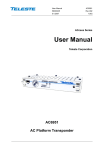
Communication Path Requirements
For serial connections: one of the connection cables connected between your PC and the desired
network element according to the following illustrations:
Local System Management interfaces
System
Connector
type
D-9 male
Connector
type
RS 232
Adapter
Cable
DVX
Interface
module
DVP3XX/432
none
(optional)
DVP3XX/432
RJ-45
DVX BUS
none
null
modem
DVX021
DVX+HFC
DMM200/201
D-9 male
RS-232
none
BK
DMM100
DBM100
BKC901/902
D-9 female
D-9 female
D-9 male
RS-232
RS-232
LMT
none
none
none
BKC900
RJ-45
BKSG
BK housing
D-9 female
-
(optional)
Connection
mode
DVX bus
Data Rate
serial IP
serial IP
serial IP
BK LMT
115200
115200
115200
none
null
modem
DBC200
DBC200
null
modem
DVX021
default
(19200)
default
(19200)
115200
BK bus
BKK901
DVX021
BK bus
default
(19200)
default
(19200)
DVX bus
2
Introduction
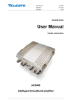
Device point-to-point interfaces
System
Connector
label
USB
Adapter
Cable
-
USB cable
AC6910/6950
Connector
type
USB miniB
RJ-45
-
none
DVX021
BKC901/902
D-9 male
LMT
none
BUA200
BUA200
-
none
null
modem
-special-
BXC100
D-9 female
SERVICE
none
DBC200
BXC900
D-9 female
SERVICE
none
DBC200
BXC901
RJ-45
SERVICE
none
DVX021
BXC902
D-9 male
SERVICE
none
DBM100
D-9 female
RS-232
none
DMM100
D-9 female
RS-232
none
null
modem
null
modem
DBC200
DMM200/201
D-9 male
RS-232
none
DSM100
D-9 female
RS-232
none
DVDXX1
PS2
RS 232
DVX021
DVO701
RJ-45
NMS
none
null
modem
DVX021
EMT100/110
D-9 female
-
EBA100
DVX021
EMT101/120
D-9 female
-
EBA100
DVX021
Vivace
D-9 male
CONTROL
none
XMT100
D-9 female
SERVICE
EBA100
null
modem
DVX021
AC6951/3000
null
modem
DBC200
Connection
mode
point-topoint
point-topoint
point-topoint
point-topoint
point-topoint
point-topoint
point-topoint
point-topoint
point-topoint
point-topoint
point-topoint
point-topoint
point-topoint
point-topoint
point-topoint
point-topoint
point-topoint
point-topoint
Data Rate
38400
115200
19200
38400
38400
19200
115200
115200
115200
115200
115200
19200
19200
19200
38400
19200
38400
Remarks:
- Teleste null modem cable type: DBC202
- DVX021 = RS-232 to RS-485 converter
Installing CATVisor™ Commander
Before beginning:
Please read the Teleste Software End-User Licence Agreement.
For new installations: Have the CD package available, as the installation program will prompt you
to type in the serial number on the package.
For upgrade installations: Write down the serial number of the existing release, as you must use
the same serial number when installing the upgrade. This can be found under the Help -> About
Commander… menu.
We advise that you uninstall any former CATVisor™ Commander versions on your system.
Installing
1. Install the CATVisor™ Commander by placing the CD-ROM in your CD/DVD) drive. The
installation program's start up screen will appear. If the start up screen does not appear
3
CATVisor™ Commander
automatically on your PC, launch the setup.exe file from the software package of your
CATVisor™ Commander CD-ROM.
2. Follow on-screen instructions. The set up program will simply guide you through the
installation.
3. Install the ‘Device DLLs’ by placing the ‘Device User Interface DLL Collection’ CD-ROM
in your CD/DVD drive.
4. Follow the on-screen instructions. The set up program will simply guide you through the
installation.
Uninstalling
Use the "Add/Remove Programs" feature in Windows Control Panel to uninstall CATVisor™
Commander.
Installing on Windows NT
1. You must first install the upgrade packet 'CD\Redist\vc6redistsetup_enu.exe'
2. Install Commander normally
3. Restart WinNT
Note! Service Pack 6 must be installed to run Commander
USB Driver Installation
The first time a Teleste USB device is connected to the PC, Windows will ask for drivers. They
should be automatically found and just require some user selections. If not they can be found in
"C:\Program Files\Common\Teleste\Drivers"
Select the telestecdc.inf to install.
During the installation Windows will ask if it should stop the installation. Select "Continue Anyway"
Note! On some laptops equiped with the IBM/Lenovo TrackPoint, Commander crashes with USB
connections. To resolve this issue disable the SynTPEnh and SynTPLpr drivers.
4
CATVisor™ Commander Tutorials
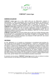
User Interface Principles
After you have opened a new or a previously saved connection, click an element in the Element
Directory (see the picture below). The CATVisor™ Commander connected view will appear
showing different types of information in three separate frames:
Parts of the Connected View
This section contains a short description of the functions of CATVisor™ Commander's frames
and menus. They will be discussed in more detail later.
Element Directory displays the structure of connections, Host Controllers as well as headend or
network segments and individual devices in them. The structure is shown in the readable form of
a hierarchical tree, showing the network elements' relative positions within the network.
5
CATVisor™ Commander
Configuration Display's display depends on the element selected in the Element Directory:
Selection in the
Element Directory
Configuration Display
Serial connection
List of connected network or headend segments with Status Flags and
information about Background Scanning and Backup Files.
USB connection
List of connected network or headend segments with Status Flags and
information
Gateway device
The gateway’s Configuration Display Pages.
DVX or HFC segment
List of devices within the segment with status flags and information
about background scanning.
Individual device
The device's configuration display pages.
Event Log lists the alarms of all elements in the Element Directory, with . date, time, source,
address, severity and message
Pull-Down Menus function as in standard Windows applications. By using them you can connect
to headends, save connection combinations, change views, update software, set the connection
properties etc.
Tool Bar contains shortcut icons for some of the Pull-Down Menus' functions as in standard
Windows applications.
Status Bar shows keyboard status information as in standard Windows applications.
Element Directory
The Element Directory displays a graphical organisation of connections, DVX/BK bus and HFC
segments and individual devices that the Commander is connected to. The directory can consist
of the following types of network elements:
Serial connection
IP Gateway device
HFC
ATMux™ Node connection
DVX/BK bus
Individual device (network element)
USB connection
The directory shows these elements in hierarchical order. Connections and segments are
displayed above individual devices and with bold font.
Alarms and Warnings
Alarms and warnings are displayed in the Element Directory with a status symbol in front of the
network element.
If a network element has a multiple alarms/warnings, only the highest severity symbol is shown.
6
CATVisor™ Commander Tutorials
Selecting Elements
When you highlight a network element in the Element Directory by clicking the desired item, the
Configuration Display will show more detailed information about it.
It is also possible to open a configuration display in a separate window e.g. for viewing/editing
several devices simultaneously.
Configuration Display
The configuration display is the device type specific display that opens when you select a device
in the Element Directory. The configuration display contains a variable number of pages for
viewing and editing the device operating parameters.
In most configuration displays the ability to edit parameters depends on the user level.
Configuration display for a connection or a DVX/BK bus/HFC segment
By clicking one of these elements, a list of devices connected through this element is shown. The
list shows each element’s current status with some basic identification data.
You can sort the element list by any column by clicking the column header. Clicking the same
header toggles between descending and ascending order.
You can change the column order by dragging the column header to the desired position.
Configuration display for an individual device
By clicking a device, the element specific configuration display is opened. Each element has its
own configuration display module with a specific selection of pages.
Event Log
The Event Log displays the alarms reported by the devices. Three severity levels are used:
Alarm, Warning and Notice. Each clearing of an alarm is indicated also as a Notice.
You can sort the Event Log by any column by clicking the column header. Clicking the same
header toggles between descending and ascending order.
You can change the column order by dragging the column header to the desired position.
Help Features
You can get help for CATVisor™ Commander in the following ways:
•
Help Menu (a pull-down menu in the program)
•
User Manual (a printed document)
7
CATVisor™ Commander
CATVisor™ Commander Menus
File Menu
New
Opens a new connection to the headend. Note that this command closes the current connections.
If you wish to open a connection in addition to the active ones, use the Connection > Add New...
function in the Connection Menu.
Open
Opens a previously saved Element Directory from file. Note that this command closes the
connections already open. If you wish to open a connection in addition to previous ones, use the
Connection > Add New... function in the Connection Menu.
Save
Saves the Element Directory database without changing its name, connection type or location.
Save As
Opens the Save As window. In this window you can select the desired connection type and file
location as well as name the Element Directory database file.
Print
In the printing options the Event Log and the Element Directory are currently available.
If you select the Event Log to be printed the standard Windows Print window opens.
If you select the Element Directory to be printed the following dialog opens:
8
CATVisor™ Commander Tutorials
•
Properties of the Selected Element prints a list of basic information about the selected
element.
•
List of All Elements prints a list of elements with Alias Names and rack positions.
•
Properties of All Elements prints a list of elements with all property fields as listed by
the Element Properties function.
Printer Setup
Opens the standard Windows Printer Setup window.
Exit
Ends your CATVisor™ Commander session and closes the program.
Note! This menu also lists up to four previously saved connections. Click one for quick access.
Edit Menu
The Edit Menu for standard Windows editing functions Undo/Cut/Copy/Paste is currently not
available. However, you can right-click in a text entry field and use these functions from the pulldown menu that opens.
View Menu
Use the View menu to hide or show parts of CATVisor™ Commander's initial view.
•
Click an item in the list to hide it and click again to show it.
•
A checked item in the list is showing.
Language Selection
On installation Commander sets the language of alarm messages to the user default language
set in the control panel of the operating system. EMS partially or fully supports the following
•
US English
•
Spannish
If Commander is on default language selection it checks if the user language is one of the
supported languages and attempts to display the alarms in that language.
If the user language is not supported the Event log will display the alarm messages as a group of
question marks "<???>". To correctly display the alarms in one of the fully supported languages
select your language preference under "view>language selection"
Commander can display all dialogs and the main program in two languages. These are
•
English
•
Spannish
9
CATVisor™ Commander
An alternative method to correctly display the alarms in one of the supported languages use
"Regional Options" in Window's control panel and set your language preference to one of the
supported or partially supported languages.
Connection Menu
Add New
Use this command to establish a new connection to the headend.
•
Click Connection > Add New... to open the Add New Connection window.
•
For more information about adding a connection, please see Adding a Connection.
Commands
This option contains some of the functions of the Element Directory Menus with which you can
modify the connection.
The Connection menu also lists the communication paths that you are using.
Settings Menu
Options
Clicking Options opens the following window:
10
CATVisor™ Commander Tutorials
By enabling Multirow pagetabs the tabs of the Configuration Display pages (see Configuration
Display Pages) will be arranged in rows. This is useful if there are so many tabs that you cannot
see all the headings.
Connection Buttons
You can customise the shortcut button settings to fit your serial port settings and frequently used
connections.
User Profile
By clicking this option you can change your user profile "on-the-fly". If you change it "upwards" to
a profile that has more privileges than your current one, the program asks for password.
Changing "downwards" can be done without a password.
Serial Number
Normally you have to enter a valid Commander serial number at the installation. However, if you
want to enable certain Commander functions afterwards with a new serial number, you can type it
in here. You will get a serial number by purchasing a license for the specific function.
PSI/IS key
If you want to enable the PSI/SI processing features, you have to type in a special PSI/SI
processing key. You will get the key by purchasing a license for the PSI/SI editor.
Tools Menu
Note! Some of these options are not available for the user profile "Guest". For other user profiles
this menu contains additional options. For example, users with at least "Service" level user profile
can update device software from this menu see Updating the Device Software.
11
CATVisor™ Commander
Load/Save Element Configuration
Note! Load/Save Element Configuration is NOT supported under Windows NT
The 'Settings Saver' function is used to store device configuration data into XML files. The stored
configuration can then be downloaded back into a module without the need to manually configure
the operating parameters. This enables quick and easy module configuration restoration in case
of e.g. device failure. With sufficient knowledge it is even possible to edit the configuration files
off-line and use them for quick installation of new modules.
The Settings Saver function is activated by the "Load Element Configuration..." and "Save
Element Configuration..." selections under the Tools menu. These selections are active only for
element types that have Settings Saver support installed. Please note that the Settings Saver
option needs the DSS 100 license that must be purchased separately for each Commander
license.
Note! While saving an elements configuration you should select the Status page and not change
viewer pages during loading/saving element settings.
Note! Only copying of settings between devices of same HW-model are possible
Send SW Reset
With this option you can send a Reset command to the selected device. Please note that a
software reset may cause a service outage in the network.
Update Element Software
With this function you can download new software to the selected element. For details please
refer to section Updating the Device Software
Broadcast Update Element Software
With this function you can download a new software to multiple elements. For details please refer
to section ‘Updating Element Software’.
Set Element Product Key
You can purchase additional properties for ATMux™ products. These properties are activated
with a product key that you will receive from a Teleste representative. Select the product in the
Element Directory, click Product key and enter your product key in the window that opens:
Help Menu
12
CATVisor™ Commander Tutorials
Help Topics
Opens the on-line help's Help Topics window. Simply follow the instruction given in this window.
About Commander…
Opens the About Commander pop-up window. It contains basic information about the program's
version, producer and copyrights. The serial number and other information in the following
example window are illustrative only.
By clicking Components or Viewers you can open windows containing Commander's
components and their version numbers. By clicking Save Info you can save this information to a
text file. Our technical support may ask you to send this file as an e-mail attachment to them for
better service.
13
CATVisor™ Commander
Element Directory Menus
Click on an element with the right mouse button in the Element Directory to open a pull-down
menu:
Menu for IP connections
Depending on the element, some of these options may not be available.
Open
Re-opens the connection.
Open New Window
Opens the element's Configuration Display as a separate, additional window. This is useful, for
example, when you want to compare the settings of two devices of same type.
Refresh
Updates the connection or device information.
Expand/Collapse (Only for IP connections)
Modifies the Element Directory's appearance as explained in Modifying the Element Directory
Appearance. These commands activate alternately.
Rename
This is a standard Windows function for renaming.
Connect/Disconnect (Not available for segments)
A disconnected element will not be in use but remains visible in the directory. Click Connect to
establish the connection again.
14
CATVisor™ Commander Tutorials
Remove
Removes the element from use and from the directory.
Element Properties
Opens the Element Properties pop-up window. This window shows basic read-only information
about the element.
Connection Settings (Not available for segments)
Click Settings to open the Connection settings window. In this window you can monitor and
change connection settings. The connection settings will be explained in more detail in chapter
Connection Settings.
Element Directory Settings
Click Element Directory Settings to open the View Settings window.
IP Address/Slot Position: Select to show the IP Address or DVX slot position
Alias name
Select to show the Alias name
Element type
Select to show the element hardware type
Either the Alias name or the Device Type must be selected. Alias name is read from the element.
If you want to change it you must do it on the device's Properties Page.
Bus address is a device's position
Select to display either the bus address or the subrack slot position. This selection is effective
only with DVX or BK bus connections.
Automatic sort arranges the directory's elements by IP address in ascending order or by Alias
name/Element type in alphabetical order.
Lookup Latest Event Message
Use this command to highlight the element's latest event message in the Event Log. See also
Event Log .
15
CATVisor™ Commander
Print
This is the same print command as in File menu. See File Menu.
Connection Settings
This dialogue is available only for connection elements. It displays the connection type with the
background scanning settings. Background scanning is a process during which Commander
automatically looks for possible new network elements on the DVX bus and refreshes the status
flags shown in the Element Directory
Interval
defines the Background Scan interval for each bus address..
Enabled
Enables the Background Scanning. If disabled, new network elements will not be found on the
DVX/BK bus.
Addresses
You can limit the scanned bus address range e.g. to prohibit from scanning non-existent DVX
subracks.
Parameters
You can change the initial connections settings here.
For more information about these settings please refer to Adding a Connection.
Click Apply to make the new settings valid or click Cancel to restore the original settings.
16
CATVisor™ Commander Tutorials
Event Log Popup Menu
You can right-click any event in the Event Log to open a pull-down menu
Save
Opens a standard Windows Save window for saving the Event Log into a text file for further
analysis.
Print
Opens a standard Windows Print window for printing of the Event Log.
Event Log Settings
See section ‘Customising the Event Log'
Tool Bar
The Toolbar contains buttons for frequently used functions.
•
Place the cursor on an icon and a tool tip will appear showing the function of this icon.
The Status Bar at the bottom of the Configuration Display shows you a longer description
of this function at the same time.
The Tool Bar also contains shortcut buttons for opening local connections (DVX, PP, RS IP, BK
LMT, BK and USB). The connection settings can be modified by using the Options command in
the Settings Menu.
17
Using Commander for Configuring and Monitoring the Network Elements
Starting CATVisor™ Commander
First, please make sure that
•
You have the CATVisor™ Commander software installed.
•
For a serial port connection: You have a suitable serial cable and/or adapter available for
the serial connection.
•
All DVX 001/002 installation frames (sub-racks) are inter-connected and each frame has
a unique subrack address (please refer to the DVX 001/002 installation instructions).
•
For an LAN/IP connection: Your PC and the network element you wish to connect to are
connected to the LAN/WAN and there is a proper IP route between them. If needed, test
the IP route by the PING command.
The Initial View
The installation program automatically places a shortcut icon to CATVisor™ Commander on your
desktop.
Click this icon to start Commander. Your screen will initially appear as seen below:
Click this icon to start Commander. Your screen will initially appear as seen below:
The program is now running, but not yet connected to any headend.
18
Using Commander for Configuring and Monitoring the Network Elements
Note! the three separate frames in the display. These frames are the basis of the program's
operation. In the next section you will open a connection to a headend to see better how these
frames function.
Establishing Connections
Adding a Connection
1. Select the Connection pull-down menu.
2. Click Add New.... to open the Add New Connection dialog.
3. Select the desired connection type from four options in the pull-down menu:
•
Serial Port establishes a local serial connection either to all DVX bus/ BK bus devices or
a point-to-point connection to a single device. See Communication Path Requirements.
The Properties field changes according to the connection type you select.
Local Connections
19
CATVisor™ Commander
Mode
The local connection modes are as follows:
•
BK Bus establishes a connection to BK bus devices.
•
BK LMT establishes a connection to the BK controller.
•
DVX Bus establishes a connection to DVX bus devices.
•
Point-to-Point establishes a connection to a specific device.
•
Serial IP establishes an IP connection over the serial connection. This connection mode
is functionally identical to the IP Gateway connection type but uses the serial connection
instead of a LAN or USB connection. It is supported only by DBM100 and DMM200.
•
USB establishes an USB connection. This connection mode is functionally identical to the
point-to-point connection type but uses the USB connection instead of a LAN or serial
connection. See USB Driver Installation
Note! The BK LMT connection is subset of the Serial IP connection with a fixed data rate and
some special features.
Properties
•
Serial Port Select the COM port that you are using for this connection from the pull-down
menu.
•
Baudrate The correct baud rate depends on the controller or the device type. Please
refer to the picture in the section ‘Communication Path Requirements’ or to the device's
installation instructions.
Note! For the BK LMT connection type the baud rate is fixed and no selection is available.
•
Poll Range This selection is available only with DVX bus and BK bus connection modes.
It allows you to limit the bus address space that is scanned when looking for installed
devices.
Remote Connections
20
Using Commander for Configuring and Monitoring the Network Elements
Mode
The remote connection modes are as follows:
•
ATMux™ Node establishes an IP connection to an ATMux™ node (Vivace or Presto)
and all ATMux™ modules reachable over the Inband communications network.
•
Direct IP (Point-to-Point) establishes an IP connection a single individual device.
•
IP Gateway (IP Host) establishes an IP connection to an IP Gateway device (DBM100,
DMM100/200, DSM100, Vivace or Presto) and to all DVX bus and HFC devices under
the gateway module.
•
IP via Serial Port connection is actually an IP Gateway connection but over the serial
line. Serial IP connections are currently supported only by DBM100 and DMM200.
•
SNMP Element uses the SNMP protocol to communicate with an element. See.
Appendix: SNMP
Properties
•
Enter the IP address or Host Name of the device you want to connect to.
Local Connection Shortcuts
You can open local connections with the Add Local selections or by the toolbar connection
buttons. Shortcuts are available for DVX bus, point-to-point, Serial IP, USB, BK LMT, BK bus
local connections and USB.
You can customise the shortcut settings with the ‘Tools-Options’ menu to fit your serial port
settings and frequently used connections.
Saving an Element Directory
Once you have made a connection you can save the element directory on to a file. This can be in
'*.eml' or '*xml' format
Note! While saving an elements configuration you should not change viewer pages during
loading/saving element settings.
21
CATVisor™ Commander
Opening a Saved Connection Database
If you have saved a connection database you can open it to the Element Directory using the
‘Open…’ command in the File menu. Opening a connection database will close all current
connection and replace them with the connections in the saved database.
Opening a saved connection database may be substantially faster than opening a new
connection, since the Commander does not have scan through the system to find the devices.
There is also the advantage that any non-communicating modules are immediately discovered.
Removing Devices from the Headend
If a device is physically removed from the system that you are connected to, a red cross symbol
appears in front of this device in the Element Directory indicating that the device is no more
communicating with the Commander:
This symbol also appears in the Configuration Display when the device is not responding. If the
device has been permanently removed from the system, you must remove it manually from the
connection database. Select the device and choose ‘Remove’ from the secondary mouse button
menu or from the ‘Connection’ toolbar menu.
Of course, you can always ‘clean out’ the Element Directory by opening a new connection and rediscover all existing elements. However, this is a slower method especially if there are a large
number of devices is the system.
Note: If you re-open a stored connection database, a removed device will reappear. To update
the connection database, remove the device manually or re-open the connection and then save
the connection database (eventually with the old name).
Adding Devices to the Element Directory
If a device is physically added to the system you are connected to while Commander is running,
the program will automatically discover the new elements. If you wish to add this device to your
Element Directory database as well, remember to save the connection database before exiting
(Commander also suggests saving upon exit).
22
Using Commander for Configuring and Monitoring the Network Elements
Using the Configuration Display
This section gives only basic information about configuring and monitoring the devices. For
LEGATO, STACCATO and VIVACE, please see On-line Helps for Configuration Displays for
more information. For other devices, please refer to their installation instructions for more
information about their Configuration Displays.
The configuration display is the device type specific display that opens when you select a device
in the Element Directory. The configuration display contains a variable number of pages for
viewing and editing the device operating parameters.
In most configuration displays the ability to edit parameters depends on the user level.
Status Page
The Status Page is always the first page in a configuration display. It is identical for all device
types and displays the device’s current alarms (alarms, warnings and notices).
The devices report alarms by raising Alarm Flags. The Commander polls the alarm flags and
interprets the information to the Status Page, the Element Directory and the Event Log.
By default the Status Page displays all alarms but you may hide the warnings and notices by
checking the corresponding check boxes. The hiding functions are non-persistent so you have to
recheck them every time you re-enter a Status Page.
The Status page is automatically updated with an interval of approximately three seconds.
Note! The alarm polling of the Element Directory and the Event Log is substantially slower than
the Status Page polling and therefore these displays may be temporarily out of sync.
Properties Page
The Properties page is normally the last page in a Configuration Display. There are a number of
different configuration pages for different device types. In all cases it shows information about the
device's hardware and software, as shown in the example below.
23
CATVisor™ Commander
On a Properties page you can also set the Alias name for selected device. The Alias name will
also be displayed in the Element Directory.
Note! ATMux™ devices have a Save Button on the Properties page. Clicking it opens the
standard Windows Save window where you can save the information on this page to a text file.
This function is needed, for example, if you need technical support from Teleste. Our technical
support may ask you to send the saved file to them for better service.
Editing the Settings
The device specific pages display the device’s operating parameters and settings. With End-user
and Service user profiles you are allowed to edit the settings. The different information is
displayed with different Windows controls, including Edit boxes, Tables, Check boxes, and Radio
buttons.
There are at least three types of information:
Read-only information may be changed only by the device itself and the user has no direct
access to this information. Read-only fields are usually shown grayed out.
Note! Fields can have read-only status also because of the current user level that does not allow
editing of all fields. With level Guest all fields should be read-only but some older configuration
displays do not support the Guest level.
Off-line editable information: Most of the numerical, alphanumerical and table type information in
the configuration displays is off-line editable. This means you can immediately select a field and
type in a new value (or Press Del or Backspace) the field updating is halted and you may type in
a new value. However, the value will be sent to the device only by pressing the ‘Apply’ button.
You may edit several fields simultaneously and send all values to the device with one ‘Apply’.
The ‘Apply’ button only becomes active after you have edited one or more values.
If do not wish to store the new value into the device, just click ‘Cancel’ and the display will re-read
the original values from the device.
On-line editable information: Certain parameters are such that it is more convenient to send the
new value immediately to the device without needing the ‘Apply’ button. Such controls are
typically radio buttons or slide controls. When using such controls, the ‘Apply’ button will not
activate and the new value will be automatically sent to the device and then re-read to give
immediate feedback.
Note! Especially with HFC devices the communication speed limits the amount of commands you
can send to the device. This can make e.g. slide controllers somewhat tricky to use and therefore
there is usually the possibility to set the controller value manually.
Refreshing the Device Information
The Configuration Displays for devices have a Refresh button. Click that button to update the
information shown on the Configuration Display pages.
Monitored Parameter Values
Parameters that are being monitored by the device itself are usually shown with a background
colour indicating the status of the parameter. The colours are analogous to the Element Directory
symbols and are as follows:
24
Using Commander for Configuring and Monitoring the Network Elements
Green: the value is within limits
Yellow: the value has exceeded one of the warning limits
Red: the value has exceeded one of the alarm limits
Blue: the value has exceeded one of the notification limits
If a parameter background is other than green, the corresponding alarm flag will be displayed on
the Status page.
On-line Helps for Configuration Displays
Currently LEGATO, STACCATO, VIVACE and PRESTO have their own on-line documentation
for their Configuration Displays included with CATVisor™ Commander. These helps work by
clicking the Help button of the Configuration Display.
Other devices' Configuration Displays do not have the Help button or it is inactive. Please refer to
their installation instructions for more information about their Configuration Displays.
25
Commander Special Features and Options
Customising the Commander User Interface
•
The minus (-) and plus (+) symbols in front of network elements function as in standard
Windows applications. You can click them to hide or show subdirectories of the Element
Directory.
•
· For IP connections that can contain very large numbers of connected elements there
are Collapse and Expand commands in the Element Directory Menus. Click Expand to
view all elements under the connection or click Collapse to see only the connection's
name. The default method for showing an IP connection is collapsed because an
automatic start for scanning large networks could cause network congestion.
Element Directory, a detailed view Element Directory, an overall view
Customising the Event Log Appearance
The Event Log can be customized by the Selection ‘Event Log Settings’. It opens the following a
dialog window:
26
Commander Special Features and Options
Show alarms/warning/notifications:
You can hide each of the severity levels by unchecking a category.
Show only latest message for each device:
When checked, only the latest alarm event for each device is shown on the Event Log.
Show Alias Name changes:
Uncheck if you don’t want to see Alias Name change events.
Show New Elements:
Uncheck if you don’t want to see New Element events.
Lookup Device:
Selects the corresponding element in the Element Directory and opens it’s configuration display.
Using Flag Suppression
Some devices support the Flag Suppression function on the Status Page. With Flag
Suppression you can set the selected device not to report some alarms that you don’t want.
Note! Flag suppression is a property of the element’s software so you have to do it separately for
every element.
The Flag Suppression button is available only for users with "Service" user profile. Clicking Flag
Suppression opens the following window:
27
CATVisor™ Commander
The window lists all possible alarm flags and their descriptions for the selected element. Deselect
the ones you want to disable. Confirm your selections by clicking Apply.
By default, all alarm flags are enabled. You can enable all of them by clicking Set All and disable
all by clicking Clear All.
If the device does not support Flag Suppression, you will see a Notice.
Background Scanning and Backup Files
When a serial connection or a headend/network segment is selected, the Configuration Display
also displays a bar showing background scanning information.
Poll addr
Displays a running number indicating the bus address being scanned. The full address range is 0
to 255.
Restart poll
By clicking this button you can start the background scanning process again from the beginning
of the address range.
Backup files
This button is used for saving device settings in files and for loading settings from files into
devices. Currently not all devices support this function. This command is useful, for example,
when a device is physically replaced with a device of the same type. Configuring the new device
is easy from a file containing the settings of the replaced device.
Note! a device must be selected in the device list to activate this button.
28
Commander Special Features and Options
Starting with Command Line Parameters
You can also start Commander by using command line parameters. By using command line
parameters you can e.g. make Windows shortcuts that automatically open a certain type
connection. This will ease up program startup and make your work more efficient.
The command line option are as follows:
Connection type
•
/s = serial connection
•
/d = LAN connection: Direct IP
•
/h = LAN connection: IP host
•
/a = LAN connection: ATMux element
Note! Currently there is no command line for USB connections.
Additional interface parameters only for serial port, delimiter = colon:
Port:
•
com1, com2 etc.
Data rate:
•
19200, 38400 or 115200
Connection mode:
•
dvx (DVX bus)
•
bk (BK Bus)
•
pp (Point-to-Point)
•
bklmt (BK LMT)
For all LAN connections an IP address is required as a parameter
Examples:
DVX bus via com1:
"c:\program files\teleste corporation\catvisor commander\commander.exe" /s com1:19200:dvx
Point-to-point connection to DMM200 via com2:
"c:\program files\teleste corporation\catvisor commander\commander.exe" /s com2:115200:pp
BK LMT via com1:
"c:\program files\teleste corporation\catvisor commander\commander.exe" /s com1:115200:bklmt
IP Host (DBM100, DMM100/200, Vivace, Presto) in IP 10.2.15.88
"c:\program files\teleste corporation\catvisor commander\commander.exe" /h 10.2.15.88
29
CATVisor™ Commander
ATMux™ node (Vivace, Presto) in IP 192.34.5.67:
"c:\program files\teleste corporation\catvisor commander\commander.exe" /a 192.34.5.67
Note! The path in the examples is Commander's default installation path. Use the path selected
during installation.
Starting Viewer Only Mode
You can start Commander from the command line or create a shortcut so that it will show only the
viewer pages for a device.
The supported connection types are:
•
DirectIP
•
Serial Point-to-point
Examples:
DirectIP
"c:\program files\teleste corporation\catvisor commander\commander.exe" /d 10.2.15.140:plain
30
Commander Special Features and Options
Serial Point-to-point
"c:\program files\teleste corporation\catvisor commander\commander.exe" /s
com1:115200:pp:plain
Note! The path in the examples is Commander's default installation path. Use the path selected
during installation.
On connection you will be presented with a window that contains only the viewer pages.
Using the Connection Database file name as a Command Line Parameter
To open a stored database immediately at startup, you can use the file name as a command line
parameter. Simply add the filename (and the path if necessary) after the Commander executable
(the connection database is also called 'Element management library').
Example:
"c:\program files\teleste corporation\Commander" d:\data\network.eml
For more information about saving and Element Directory, see chapter ‘Saving an Element
Directory’.
31
CATVisor™ Commander
By using these command line parameters it is also possible to create shortcuts on your desktop
for easy program startup:
1. Right-click your mouse on the desktop.
2. Select New/Shortcut
3. Type a command line in the Create Shortcut window that opens.
Updating the Device Software
With the help of CATVisor™ Commander you can load application software updates to the
devices. S-record files with extensions srec and s2 also accept firmware as update target.
Element software can be updated only by users with at least "Service" level user profile. There is
also the Broadcast Update Element Software option for updating several devices of same type at
the same time. For this you will need to enter a broadcast address but after that the process is
the same as described below.
1. Select a device in the Element Directory.
2. Click Update Element Software… in the Tools menu to open the Open window.
3. Browse for the update file (in .hex, .srec, .s2 or .mot formats) and click Open. The
update preprocess starts automatically.
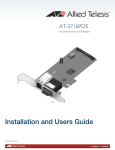
4. The blue indicator bars in the Preprocess field show the progress and remain full when
preprocessing is finished. The Software Update window will then appear as below:
32
Commander Special Features and Options
Under download options you will find more detailed settings are available.
CAUTION! Uncheck the Bus reserved safemode enabled check box only if you are sure
that your PC is the only master of the bus. The update process may be a little faster when
Bus reserved safemode is disabled, but the process will fail if some other device takes
control of the bus during the download.
5. Enter the Device model and HW version if prompted. You will find them on the
Properties page. Select the Download method from the pull-down menu:
Synchronised
Synchronous communication is used in downloading. Each packet will be checked before
sending the next.
Send and Check
Asynchronous communication is used in downloading. Each packet will be checked before
sending the next.
Fast
Asynchronous communication is used in downloading. Packets are sent on regular
intervals until no packets are left.
33
CATVisor™ Commander
Combined Lines
As many data lines as possible will be combined into each packet. Asynchronous
communication is used in downloading. Packets are sent and stored to a communication
buffer on regular intervals until no packets are left.
6. Click Update. The updating process may take a few minutes. The blue indicator bars in
the Software update field and the text field at the bottom of the window show the
progress.
7. When the process is finished, a Software updated successfully notification appears
briefly and the blue bars remain full indicating that the application software is updated.
Close the Software Update window by clicking Close.
8. Some digital devices need the Reset command in the Tools menu to start the new
application software. If the Reset command is not available, just select the device in the
Element Directory again.
Note! With some devices a physical power-off and on will be required. Please refer to the
device's installation instructions for more details.
34
Commander Special Features and Options
SNMP
General Overview
Commander 2.5 and higher versions provide limited SNMP functions. SNMP network elements
can be manually added to the element directory one by one to establish a common system view
with traditional non-SNMP elements. The directory contents can then be stored on disk and the
next time Commander is used the connections can be quickly restored without the need to
manually add all the SNMP elements again.
When adding an SNMP element to an element directory, the user must define the IP address and
change the SNMP read and write communities and the UDP destination port number, if the
defaults can not be used. The user may also type a name for the element, to distinguish it from
other SNMP elements on the directory tree.
Once added to the element directory, SNMP elements can be configured in the same way as
traditional network elements. This requires that a compatible SNMP viewer DLL is installed and
configured to the system. The exact functions available depends on the viewer properties.
The following limitations apply to SNMP elements:
•
only LAN (IP) connections are supported
•
there is no automatic discovery available, all SNMP elements must be added manually to
the element directory, one-by-one
•
no identification data is automatically retrieved to the element directory from the element
•
the presence or alarms of SNMP elements are not monitored
MIB Database
MIB database consists of a number of files of special format, which store MIB information used by
the product to view and edit SNMP variables of the target devices.
MIB database files are located in a dedicated directory. By default this is "C:\Program
Files\Common Files\Teleste\MibBase"
Preloading information
Since MIB information can potentially consist of many MIB variables described in a big number of
files, loading the whole set of MIB information at once may slow down the system. Instead, MIB
35
CATVisor™ Commander
information is loaded on demand by viewers and other components that want to use MIB
information.
A viewer or other component typically knows exactly what kind of MIB information it needs (and
therefore can ask MIB database to load the needed files). However, in some cases this
knowledge might is not available to the viewer (e.g. when working with MIB variables which
reference other MIB variables, like HMS alarm information).
To let viewers and other components access all MIB information they might need, it is possible to
specify that some MIB databases are preloaded. This is achieved with the help of MIB preloading
information.
MIB preloading information is be specified in a file named “MibInfo.txt”. This file is located in the
product installation directory and uses the standard Windows '.ini' file format.
MIB preloading can be done either based on sysOID or on IP address. If both are specified, the
IP address takes precedence. Section name “All” defines the MIB files preloaded for all elements.
Example:
; MIB files to use with address 10.2.14.165
[IP-10.2.14.165]
MIB-2-System.txt
bkModules1.txt
bkStation.txt
If you want to specify which MIB files must be loaded when the application works with an SNMP
agent with a specific MIB-2 sysObjectId, add section with name “OID-sysObjectId” to the file and
specify the list of MIB files as entries in the section.
Example:
; MIB files to use with 1.3.6.1.4.1.4761 (NuDesign)
[OID-1.3.6.1.4.1.4761]
Teleste-EMS.txt
If you want to specify which MIB files must be always loaded, add section with name “All” to the
file and specify the list of MIB files as entries in the section.
Example:
; MIB files that are always loaded
[All]
MIB-2-System.txt
Note! MIB database supports full and relative file paths. If the relative path is given, it is
appended to the end of the MIB file path pre-configured in the Registry.
Example:
; Full and relative file path example
[All]
; Full path
c:\mibfiles\MIB-2-System.txt
36
Commander Special Features and Options
; Relative path – will be expanded to <MibFilePath>\hms\HMS-commonIdent.txt
hms\HMS-commonIdent.txt
Note! If the same file is specified in MIB preloading information more than once, it does not cause
any significant performance overhead. This is because MIB database checks if a file is already
loaded, and does not load already loaded files again.
Complete example:
; MIB files which are always loaded
[All]
MIB-2-System.txt
; MIB files to use with all SNMP Wizard installations
[OID-1.3.6.1.4.1.4761]
Teleste-EMS.txt
; MIB files to use with the device at 10.2.14.165
[IP-10.2.14.165]
bkModules1.txt
bkStation.txt
HMS-commonIdent.txt
HMS-propertyIdent.txt
Viewer Database
The Viewer Database defines the viewer pages displayed for each HMS/SNMP element type,
using the MIB-2 sysOID as the key.
Location
The viewer database is the file “Userviewers.txt” located in the product installation directory.
File format details
Userviewers.txt uses standard Windows '.ini' file format, where section names contain the
sysOID of the agent and a list of viewer pages to be displayed for that device.
If a line starts with a ‘;’ character, it is considered a comment.
If you want to use a specific set of viewer pages for a device type you can add, remove and
reorder the viewer page definitions, or add completely new sections.
Put the device's sysOID in square brackets and place the list of viewer page identifiers beneath.
The viewer programmatic ID can be specified. The viewer pages will be displayed exactly in the
order defined.
The programmatic IDs of each viewer page are given in the viewer DLL documentation.
37
CATVisor™ Commander
Example:
; BK Station
[1.3.6.1.4.1.3715.3.1]
HmsPages.HmsStatusPage
BKSnmp.DevicePage
HmsPages.HmsAlarmLogPage
;HmsPages.HmsCommonPage
HmsPages.AnalogAlarmsPage
HmsPages.DiscreteAlarmsPage
;HmsPages.HmsMACPage
MIB2.Mib2SystemPage
;MIB2.Mib2SnmpPage
Note! If a non-standard viewer layout is needed for selected devices, it can be defined in the
Device Database.
Device Database
The Device database stores SNMP specific information for selected devices, using IP address as
the key. For any device, it is possible to specify the following information:
Address
IP address of the device
Port*
UDP target port number that should be used to communicate
with the device.
Read community*
SNMPv1 read community used in communications with the
device.
Write community*
SNMPv1 write community used in communications with the
device.
Viewer (CLSID or
programmatic ID)
The Viewer that should be used for this device. Either viewer
CLSID or programmatic ID can be specified. If both are
specified, CLSID takes precedence.
Location
Device database is located in the product installation directory, in the file with name
“Devices.txt”.
File format details
Device database uses standard Windows '.ini' file format, where section names contain the IP
addresses of the devices. There is also section named “Default”, which is used to specify default
values for all settings which are not specified in their device’s section in the file.
Settings are specified as entries under the corresponding section, where entry name and value
are separated by ‘=’ character.
If a line is started with ‘;’ character, it is considered a comment.
38
Commander Special Features and Options
List of settings:
Setting
Entry Name
Example
Port
Port
port=161
Read community
ReadCommunity
ReadCommunity=public
Write community
WriteCommunity
WriteCommunity=private
Viewer CLSID
Viewer
Viewer= {E33F888B-A3BC-4C5C-9E2C2731EA0F7216}
Viewer programmatic
ID
ViewerProgID
ViewerProgID=BKSnmp.BKSnmpViewer.1
Example:
; Default settings
[Default]
Port=161
ReadCommunity=public
WriteCommunity=private
Viewer={E33F888B-A3BC-4C5C-9E2C-2731EA0F7216}
; Settings for localhost
[127.0.0.1]
Port=171
; Settings for 10.2.14.167
[10.2.14.167]
ViewerProgID=BKSnmp.BKSnmpViewer.1
See:
Default Settings
* In Commander and EMS Explorer, this information is overridden by the corresponding data in
the Element database.
Default Settings
Destination address
127.0.0.1
Destination port
161
Read community
public
Write community
private
Viewer
MIB-2 System and SNMP pages
The following items are the main changes in this version of CATVisor™ Commander help.
•
USB Driver Installation
•
USB connection
39
CATVisor™ Commander
Contact Information
Teleste Corporation produced this document. For more information about this document please
quote product code:
PEM303-E
Teleste Corporation
P.O. Box 323
FIN-20101 Turku
FINLAND
http://www.teleste.com
If you need support from Teleste, please have the version & build numbers of your application
available. You can find them in the About section in the Help menu.
40