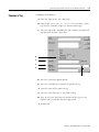
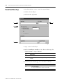
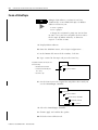
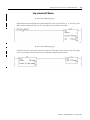
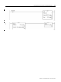
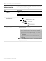
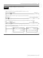
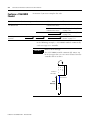
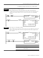
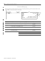
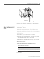
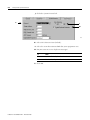
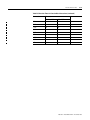
1
ControlLogix™ System 1756-L1, -L1Mx, -L55Mxx, -L63 User Manual File Name: AB_ControlLogix_1756_L1_L1Mx_L5Mxx_L63_user_D1101 Important User Information Because of the variety of uses for the products described in this publication, those responsible for the application and use of these products must satisfy themselves that all necessary steps have been taken to assure that each application and use meets all performance and safety requirements, including any applicable laws, regulations, codes and standards. In no event will Allen-Bradley be responsible or liable for indirect or consequential damage resulting from the use or application of these products. Any illustrations, charts, sample programs, and layout examples shown in this publication are intended solely for purposes of example. Since there are many variables and requirements associated with any particular installation, Allen-Bradley does not assume responsibility or liability (to include intellectual property liability) for actual use based upon the examples shown in this publication. Allen-Bradley publication SGI-1.1, Safety Guidelines for the Application, Installation and Maintenance of Solid-State Control (available from your local Allen-Bradley office), describes some important differences between solid-state equipment and electromechanical devices that should be taken into consideration when applying products such as those described in this publication. Reproduction of the contents of this copyrighted publication, in whole or part, without written permission of Rockwell Automation, is prohibited. Throughout this publication, notes may be used to make you aware of safety considerations. The following annotations and their accompanying statements help you to identify a potential hazard, avoid a potential hazard, and recognize the consequences of a potential hazard: WARNING ! ATTENTION ! IMPORTANT Identifies information about practices or circumstances that can cause an explosion in a hazardous environment, which may lead to personal injury or death, property damage, or economic loss. Identifies information about practices or circumstances that can lead to personal injury or death, property damage, or economic loss. Identifies information that is critical for successful application and understanding of the product. Summary of Changes Introduction This release of this document contains new and updated information. To find new and updated information, look for change bars, as shown next to this paragraph. Updated Information The document contains the following changes: This new or updated information: Starts on page: Communicate with an RSView Project over an EtherNet/IP Network 7-1 Communicate with 1771 I/O Over a ControlNet™ Network 9-1 Communicate with an RSView Project over a ControlNet™ Network 14-1 1 Communicate Over a Remote I/O Network 20-1 Program Motion Control 24-1 Estimate Battery Life 25-1 Estimate Execution Time B-1 Estimate Memory Use C-1 Reconfigure an I/O module E-1 Publication 1756-UM001D-EN-P - November 2001 Summary of Changes 2 Notes: Publication 1756-UM001D-EN-P - November 2001 Preface Purpose of this Manual This manual guides the development of projects for ControlLogix controllers. It provides step-by-step procedures on how to establish communications: • over the following networks – EtherNet/IP – ControlNet™ – remote I/O – DH+™ – DH-485 – serial • with the following devices – controllers – I/O – workstations – PanelView™ terminals This manual works together with the Logix5000 Controllers Common Procedures, publication 1756-PM001, which covers the following tasks: • • • • • • Who Should Use this Manual This manual is intended for those individuals who program applications that use ControlLogix controllers, such as: • • • • 1 Manage project files Organize your logic Organize tags Program routines Test a project Handle faults software engineers control engineers application engineers instrumentation technicians Publication 1756-UM001D-EN-P - November 2001 Preface 2 When to Use this Manual Use this manual: • when you are ready to integrate your application with the I/0 devices, controllers, and networks in your system. • after you perform these actions: – develop the basic code for your application – perform isolated tests of your application How to Use this Manual This manual is divided into the basic tasks that you perform while programming a ControlLogix controller. • Each chapter covers a task. • The tasks are organized in the sequence that you will typically perform them. As you use this manual, you will see some terms that are formatted differently from the rest of the text: Text that is: Identifies: Italic the actual name of an item that you Right-click User-Defined … see on your screen or in an example Right-click on the item that is named User-Defined. courier information that you must supply based on your application (a variable) You must identify the specific program in your application. Typically, it is a name or variable that you have defined. Publication 1756-UM001D-EN-P - November 2001 For example: Right-click name_of_program … Means: Table of Contents Chapter 1 Configure an EtherNet/IP Module When to Use This Procedure . . . . . . . . . . . . . . . . Before You Begin . . . . . . . . . . . . . . . . . . . . . . . . RSLogix 5000 Software . . . . . . . . . . . . . . . . . . RSLinx Software . . . . . . . . . . . . . . . . . . . . . . . BOOTP Server Software . . . . . . . . . . . . . . . . . How to Use This Procedure. . . . . . . . . . . . . . . . . Configure a Module Using RSLogix 5000 Software Connect the Hardware . . . . . . . . . . . . . . . . . . Connect to the Module. . . . . . . . . . . . . . . . . . Configure the Port . . . . . . . . . . . . . . . . . . . . . Check the Module . . . . . . . . . . . . . . . . . . . . . Configure a Module Using RSLinx Software . . . . . Connect the Hardware . . . . . . . . . . . . . . . . . . Configure the Port . . . . . . . . . . . . . . . . . . . . . Check the Module . . . . . . . . . . . . . . . . . . . . . Configure a Module Using BOOTP . . . . . . . . . . . Install BOOTPServer Software . . . . . . . . . . . . Connect the Hardware . . . . . . . . . . . . . . . . . . Enter the Default Network Settings . . . . . . . . . Configure the Module . . . . . . . . . . . . . . . . . . Disable BOOTP . . . . . . . . . . . . . . . . . . . . . . . Save the Relation List . . . . . . . . . . . . . . . . . . . Renew the IP Address of a 1794-AENx Module. . . Install BOOTPServer Software . . . . . . . . . . . . Set Up the Hardware . . . . . . . . . . . . . . . . . . . Enter the New Configuration . . . . . . . . . . . . . Send the Configuration. . . . . . . . . . . . . . . . . . Disable BOOTP . . . . . . . . . . . . . . . . . . . . . . . Save the Relation List . . . . . . . . . . . . . . . . . . . Test the Configuration. . . . . . . . . . . . . . . . . . . . . Connect Directly to a Controller. . . . . . . . . . . . . . Connect a Serial Cable . . . . . . . . . . . . . . . . . . Configure a Serial Driver . . . . . . . . . . . . . . . . . . . . . . . . . . . . . . . . . . . . . . . . . . . . . . . . . . . . . . . . . . . . . . . . . . . . . . . . . . . . . . . . . . . . . . . . . . . . . . . . . . . . . . . . . . . . . . . . . . . . . . . . . . . . . . . . . . . . . . . . . . . . . . . . . . . . . . . . . . . . . . . . . . . . . . . . . . . . . . . . . . . . . . . . . . . . . . . . . . . . . . . . . . . . . . . . . . . . . . . . . . . . . . . . . . . . . . . . . . . . . . . . . . . . . . . 1-1 1-2 1-3 1-4 1-5 1-6 1-7 1-7 1-8 1-10 1-12 1-13 1-13 1-13 1-15 1-16 1-16 1-16 1-17 1-18 1-19 1-19 1-20 1-20 1-20 1-21 1-22 1-22 1-23 1-24 1-24 1-24 1-26 . . . . . . . . . . . . . . . . . . . . . . . . . . . . 2-1 2-1 2-2 2-3 Chapter 2 Download and Go Online over an EtherNet/IP Network i When to Use This Procedure . How to Use This Procedure. . Configure an Ethernet Driver . Select a Path . . . . . . . . . . . . . . . . . . . . . . . . . . . . . . . . . . . . . . . . . . . . . . . . . . . . . . . . . . . . . . . . . . . . . . . . . Publication 1756-UM001D-EN-P - November 2001 Table of Contents ii Chapter 3 Communicate with 1756 I/O over an EtherNet/IP Network When to Use This Procedure . . . . . . . . . . . . . . Before You Begin . . . . . . . . . . . . . . . . . . . . . . How to Use This Procedure. . . . . . . . . . . . . . . Add the Local 1756-ENBx or -ENET Module . . . Add the Remote 1756-ENBx or -ENET Module . Add I/O Modules . . . . . . . . . . . . . . . . . . . . . . Create Aliases . . . . . . . . . . . . . . . . . . . . . . . . . Validate Connections. . . . . . . . . . . . . . . . . . . . . . . . . . . . . . . . . . . . . . . . . . . . . . . . . . . . . . . . . . . . . . . . . . . . . . . . . . . . . . . . . . . . . . . . . . . . 3-1 3-1 3-2 3-3 3-5 3-8 3-12 3-15 . . . . . . . . . . . . . . . . . . . . . . . . . . . . . . . . . . . . . . . . . . . . . . . . . . . . . . . . . . . . . . . . . . . . . . . . . . . . . . . . 4-1 4-2 4-2 4-3 4-5 4-8 4-11 4-13 When to Use This Procedure . . . . . . . . . . . . . . Before You Begin . . . . . . . . . . . . . . . . . . . . . . Select a Communication Method . . . . . . . . . . . Produce a Tag . . . . . . . . . . . . . . . . . . . . . . . . Add the Local 1756-ENBx or -ENET Module . . . Add the Remote 1756-ENBx or -ENET Module . Add the Other Controller. . . . . . . . . . . . . . . . . Consume a Tag. . . . . . . . . . . . . . . . . . . . . . . . Validate Connections. . . . . . . . . . . . . . . . . . . . Does Another Controller Require the Data? . . . Add the Local 1756-ENBx or -ENET Module . . . Enter a Message . . . . . . . . . . . . . . . . . . . . . . . Configure the Message . . . . . . . . . . . . . . . . . . Stagger the Messages. . . . . . . . . . . . . . . . . . . . Access ControlLogix Data . . . . . . . . . . . . . . . . . . . . . . . . . . . . . . . . . . . . . . . . . . . . . . . . . . . . . . . . . . . . . . . . . . . . . . . . . . . . . . . . . . . . . . . . . . . . . . . . . . . . . . . . . . . . . . . . . . . . . . . . . . . . . . . . . . . . . . . . . . . . . . . . . . . . . . . 5-1 5-1 5-2 5-3 5-4 5-6 5-9 5-11 5-12 5-13 5-14 5-16 5-18 5-22 5-23 Chapter 4 Communicate with 1794 I/O Over an EtherNet/IP Network When to Use This Procedure . . . . . . . . . . . Before You Use This Procedure. . . . . . . . . How to Use This Procedure. . . . . . . . . . . . Add the local 1756-ENBx or -ENET module Add the Remote 1794-AENx Module . . . . . Add I/O Modules . . . . . . . . . . . . . . . . . . . Address I/O . . . . . . . . . . . . . . . . . . . . . . . Validate Connections. . . . . . . . . . . . . . . . . . . . . . . . . . . . . . . . . Chapter 5 Communicate with Another Controller over an EtherNet/IP Network Publication 1756-UM001D-EN-P - November 2001 Table of Contents iii Chapter 6 ™ Communicate with a PanelView Terminal Over a EtherNet/IP Network When to Use This Procedure . . . . . . . . . . . . Before You Begin . . . . . . . . . . . . . . . . . . . . How to Use This Procedure. . . . . . . . . . . . . Add the Local 1756-ENBx or -ENET Module . Add the PanelView Terminal . . . . . . . . . . . . Organize Your Data . . . . . . . . . . . . . . . . . . Configure the PanelView Terminal. . . . . . . . Create PanelView Tags . . . . . . . . . . . . . . . . Validate Connections. . . . . . . . . . . . . . . . . . . . . . . . . . . . . . . . . . . . . . . . . . . . . . . . . . . . . . . . . . . . . . . . . . . . . . . . . . . . . . . . . . . . . . . . . . . . . . . . . . . . . . . . . . . . . . . . . . . . . 6-1 6-1 6-2 6-3 6-5 6-8 6-10 6-12 6-14 . . . . . . . . . . . . . . . . . . . . . . . . . . . . . . . . . . . . . . . . . . . . . . . . . . . . . . . . . . . . . . . . . . . . . . . . . . . . . . . . . . . . . . . . . . . . . . . . . . . . . . . . . . . . . . . . . . . . . . . . . . . . . . . . . . . . . . . . . . . . . . . . . . . . . . . . . . . . . . . . . . . . . . . . . . . . . . . . . . . . . . . . . . . . . . . . . . . . . . . . . . . . . . . . . 7-1 7-1 7-2 7-3 7-4 7-6 7-7 7-7 7-8 7-8 7-10 7-12 7-14 7-16 7-18 7-20 7-22 7-23 7-24 Chapter 7 Communicate with an RSView Project over an EtherNet/IP Network When to Use This Procedure . . . . . . . . . . . . How to Use This Procedure. . . . . . . . . . . . . Configure an Ethernet Driver . . . . . . . . . . . . Select a Communication Method . . . . . . . . . Create a Polled Topic . . . . . . . . . . . . . . . . . Create a Polled Node . . . . . . . . . . . . . . . . . Import Logix5000 Tags . . . . . . . . . . . . . . . . Create an .L5K File. . . . . . . . . . . . . . . . . Install the Logix 5000 Tag Import Utility . Use the Utility to Create a .CSV File . . . . Import the .CSV File. . . . . . . . . . . . . . . . Create a Polled Tag. . . . . . . . . . . . . . . . . . . Create a Unsolicited Topic. . . . . . . . . . . . . . Add the 1756-ENBx or -ENET Module . . . . . Enter a Message . . . . . . . . . . . . . . . . . . . . . Configure the Message . . . . . . . . . . . . . . . . Create an Unsolicited Node . . . . . . . . . . . . . Create an Unsolicited Tag . . . . . . . . . . . . . . Validate an RSView32 Tag . . . . . . . . . . . . . . Chapter 8 Communicate with 1756 I/O over a When to Use This Procedure . . . . . . . . . . . . . . . . . . . . . . . 8-1 How to Use This Procedure. . . . . . . . . . . . . . . . . . . . . . . . 8-1 ControlNet™ Network Add the Local 1756-CNB Module . . Add the Remote 1756-CNB Module Add I/O Modules . . . . . . . . . . . . . Create Aliases . . . . . . . . . . . . . . . . Schedule the ControlNet Network . Validate Connections. . . . . . . . . . . . . . . . . . . . . . . . . . . . . . . . . . . . . . . . . . . . . . . . . . . . . . . . . . . . . . . . . . . . . . . . . . . . . . . . . . . . . . . . . . . . . . . . . . . . . . . . . . . . . . . . . . . . . . . 8-2 8-4 8-6 8-10 8-13 8-14 Publication 1756-UM001D-EN-P - November 2001 Table of Contents iv Chapter 9 Communicate with 1771 I/O Over a When to Use This Procedure . . . . . . . . . . . . . . . . . . . . . . . 9-1 How to Use This Procedure. . . . . . . . . . . . . . . . . . . . . . . . 9-1 ControlNet™ Network Add the Local 1756-CNB Module . . . . . . . . . . . . . . . . . . . . 9-3 Add the 1771-ACN Module . . . . . . . . . . . . . . . . . . . . . . . . 9-5 Read or Write Data To or From a Block Transfer Module . . 9-7 Read Data From a Block Transfer Module . . . . . . . . . . . 9-8 Write Configuration or Output Data To a Block Transfer Module . . . . . . . . . . . . . . . . . . . . . . . . . . . . . . . . . . . . 9-10 Configure the Messages . . . . . . . . . . . . . . . . . . . . . . . . 9-11 Read or Write Data To or From Multiple Block Transfer Modules 9-12 Create a User-Defined Data Type . . . . . . . . . . . . . . . . . 9-13 Create the Array for the Input Data. . . . . . . . . . . . . . . . 9-14 Send a Block Transfer Read Message . . . . . . . . . . . . . . 9-15 Enter the BTR Properties for Each Module . . . . . . . . . . 9-17 Convert the INTs to DINTs . . . . . . . . . . . . . . . . . . . . . . 9-18 Step to the Next BT Module . . . . . . . . . . . . . . . . . . . . . 9-19 Write Data to Multiple Block Transfer Modules . . . . . . . 9-20 Address I/O . . . . . . . . . . . . . . . . . . . . . . . . . . . . . . . . . . . 9-22 Schedule the ControlNet Network . . . . . . . . . . . . . . . . . . . 9-24 Validate Connections. . . . . . . . . . . . . . . . . . . . . . . . . . . . . 9-25 Stagger the Messages. . . . . . . . . . . . . . . . . . . . . . . . . . . . . 9-27 Chapter 10 Communicate with 1794 I/O Over a When to Use This Procedure . . . . . . . . . . . . . . . . . . . . . . . 10-1 How to Use This Procedure. . . . . . . . . . . . . . . . . . . . . . . . 10-1 ControlNet™ Network Add the local 1756-CNB module . . Add the Remote 1794-ACN Module Add I/O Modules . . . . . . . . . . . . . Create Aliases . . . . . . . . . . . . . . . . Schedule the ControlNet Network . Validate Connections. . . . . . . . . . . . . . . . . . . . . . . . . . . . . . . . . . . . . . . . . . . . . . . . . . . . . . . . . . . . . . . . . . . . . . . . . . . . . . . . . . . . . . . . . . . . . . . . . . . . . . . . . . . . . . . . . . 10-2 . 10-4 . 10-6 10-10 10-13 10-14 When to Use This Procedure . . . . . . . . . . . How to Use This Procedure. . . . . . . . . . . . Step 1: Add the 1756-CNB Module. . . . . . . Step 2: Add the Remote 1756-CNB Module. Step 3: Add the 1788-CNC Module . . . . . . . Step 4: Add the Other Controller . . . . . . . . Step 5: Enter a Message. . . . . . . . . . . . . . . Step 6: Configure the Message . . . . . . . . . . Step 7: Stagger the Messages . . . . . . . . . . . Step 8: Access ControlLogix Data. . . . . . . . . . . . . . . . . . . . . . . . . . . . . . . . . . . . . . . . . . . . . . . . . . . . . . . . . . . . . . . . . . . . . . . . . . . . . . . . . . . . . . . . . . . . . . . . . . . . . . . . . . . . . . . . . . . . . . . 11-1 . 11-2 . 11-3 . 11-5 . 11-8 11-10 11-12 11-14 11-16 11-16 Chapter 11 Communicate with Another Controller over a ControlNet™ Network Publication 1756-UM001D-EN-P - November 2001 Table of Contents v Chapter 12 ® Route PLC-5 Messages Between When to Use This Procedure . . . . . . . . . . . . . . . . . . . . . . . 12-1 Route a ControlNet Message . . . . . . . . . . . . . . . . . . . . . . . 12-2 ControlNet™ Networks Chapter 13 Communicate with a PanelView™ ™ Terminal Over a ControlNet Network When to Use This Procedure . . . . . How to Use This Procedure. . . . . . Add the Local 1756-CNB Module . . Add the PanelView Terminal . . . . . Organize Your Scheduled Data . . . Organize Your Unscheduled Data . Configure the PanelView Terminal. Create PanelView Tags . . . . . . . . . Schedule the ControlNet Network . Validate Connections. . . . . . . . . . . . . . . . . . . . . . . . . . . . . . . . . . . . . . . . . . . . . . . . . . . . . . . . . . . . . . . . . . . . . . . . . . . . . . . . . . . . . . . . . . . . . . . . . . . . . . . . . . . . . . . . . . . . . . . . . . . . . . . . . . . . . . . . . . . . . . . . . . . . . . . . . . . . . . . . . . . . . . . . . . . . . . . . . . . . . . 13-1 . 13-2 . 13-2 . 13-5 . 13-8 13-10 13-12 13-14 13-16 13-17 When to Use This Procedure . . . . . . . . . . . . How to Use This Procedure. . . . . . . . . . . . . Configure a ControlNet Driver . . . . . . . . . . . Select a Communication Method . . . . . . . . . Create a Polled Topic . . . . . . . . . . . . . . . . . Create a Polled Node . . . . . . . . . . . . . . . . . Import Logix5000 Tags . . . . . . . . . . . . . . . . Create an .L5K File. . . . . . . . . . . . . . . . . Install the Logix 5000 Tag Import Utility . Use the Utility to Create a .CSV File . . . . Import the .CSV File. . . . . . . . . . . . . . . . Create a Polled Tag. . . . . . . . . . . . . . . . . . . Create a Unsolicited Topic. . . . . . . . . . . . . . Add the 1756-CNB Module . . . . . . . . . . . . . Enter a Message . . . . . . . . . . . . . . . . . . . . . Configure the Message . . . . . . . . . . . . . . . . Create an Unsolicited Node . . . . . . . . . . . . . Create an Unsolicited Tag . . . . . . . . . . . . . . Validate an RSView32 Tag . . . . . . . . . . . . . . . . . . . . . . . . . . . . . . . . . . . . . . . . . . . . . . . . . . . . . . . . . . . . . . . . . . . . . . . . . . . . . . . . . . . . . . . . . . . . . . . . . . . . . . . . . . . . . . . . . . . . . . . . . . . . . . . . . . . . . . . . . . . . . . . . . . . . . . . . . . . . . . . . . . . . . . . . . . . . . . . . . . . . . . . . . . . . . . . . . . . . . . . . . . . . . 14-1 . 14-1 . 14-2 . 14-3 . 14-4 . 14-6 . 14-7 . 14-7 . 14-8 . 14-8 14-10 14-12 14-14 14-16 14-18 14-20 14-22 14-23 14-24 Chapter 14 Communicate with an RSView Project over a ControlNet™ Network Chapter 15 Monitor Connections When To Use This Procedure . . . . . . . . . . . . . . . . . . . . . . 15-1 Monitor a Connection . . . . . . . . . . . . . . . . . . . . . . . . . . . . 15-2 Publication 1756-UM001D-EN-P - November 2001 Table of Contents vi Chapter 16 Communicate with a DeviceNet Device When to Use This Procedure . . . . . . . How to Use This Procedure. . . . . . . . Step 1: Add the 1756-DNB Module . . Step 2: Create Aliases . . . . . . . . . . . . Step 3: Set the Scanner to Run Mode . . . . . . . . . . . . . . . . . . . . . . . . . . . . . . . . . . . . . . . . . . . . . . . . . . . . . . . . . . . . . . . . . . . . . . . . . . . . . . . . . 16-1 16-1 16-1 16-4 16-6 . . . . . . . . . . . . . . . . . . . . . . . . . . . . . . . . . . . . . . . . . . . . . . . . . . . . . . . . . . . . . . . . . . . . . . . . . . . . . . . . . . . . . . . . . . . . . . . . . . . . . . . . . . . . . . . . . . . . . . . . . . . . . . . . . . . . . . . . 17-1 . 17-2 . 17-3 . 17-8 17-11 17-14 17-16 17-20 17-20 Chapter 17 Communicate with Another Controller Over a DH+™ Network When to Use This Procedure . . . . . How to Use This Procedure. . . . . . Configure Routing Tables . . . . . . . Configure a 1756-DHRIO Channel . Add a 1756-DHRIO Module. . . . . . Enter a Message . . . . . . . . . . . . . . Configure the Message . . . . . . . . . Stagger the Messages. . . . . . . . . . . Access ControlLogix Data . . . . . . . . . . . . . . . . . . . . . . . . . Chapter 18 ® ™ Route PLC-5 or SLC 500 When to Use This Procedure . . . . . . . . . . . . . . . . . . . . . . . 18-1 ™ Messages From a DH+ Network Configure Routing Tables . . . . . . . . . . . . . . . . . . . . . . . . . 18-2 Configure a PLC-5 or SLC 500 Message . . . . . . . . . . . . . . . 18-6 Chapter 19 Communicate with Another When to Use this Procedure . . . . . . . . . . . . . . . . . . . . . . . 19-1 Controller over a DH-485 Network How to Use This Procedure. . . . . . . . . . . . . . . . . . . . . . . . 19-2 Step Step Step Step Step Step Publication 1756-UM001D-EN-P - November 2001 1: 2: 3: 4: 5: 6: Connect the Controller to an AIC+ Configure the Serial Port . . . . . . . Enter a Message. . . . . . . . . . . . . . Configure the Message . . . . . . . . . Check the LED. . . . . . . . . . . . . . . Stagger the Messages . . . . . . . . . . . . . . . . . . . . . . . . . . . . . . . . . . . . . . . . . . . . . . . . . . . . . . . . . . . . . . . . . . . . . . . . . . . . . . . . . . . 19-3 . 19-4 . 19-6 . 19-8 19-10 19-10 Table of Contents vii Chapter 20 Communicate Over a Remote I/O Network When to Use This Procedure . . . . . . . . . . . . . . . . . . . . . . . 20-1 How to Use This Procedure. . . . . . . . . . . . . . . . . . . . . . . . 20-2 Add a 1756-DHRIO Module. . . . . . . . . . . . . . . . . . . . . . . . 20-3 Add a Remote I/O Adapter . . . . . . . . . . . . . . . . . . . . . . . . 20-6 Add a Block Transfer Module . . . . . . . . . . . . . . . . . . . . . . 20-9 Read or Write Data To or From a Block Transfer Module . 20-10 Read Data From a Block Transfer Module . . . . . . . . . . 20-11 Write Configuration or Output Data To a Block Transfer Module . . . . . . . . . . . . . . . . . . . . . . . . . . . . . . . . . . . 20-13 Configure the Messages . . . . . . . . . . . . . . . . . . . . . . . 20-14 Read or Write Data To or From Multiple Block Transfer Modules 20-15 Create a User-Defined Data Type . . . . . . . . . . . . . . . . 20-17 Create the Data Array. . . . . . . . . . . . . . . . . . . . . . . . . 20-18 Send the Message to a BT Module . . . . . . . . . . . . . . . 20-19 Enter the Message Properties for Each Module . . . . . . 20-21 Convert the INTs to DINTs . . . . . . . . . . . . . . . . . . . . . 20-22 Step to the Next BT Module . . . . . . . . . . . . . . . . . . . . 20-23 Write Data to Multiple Block Transfer Modules . . . . . . 20-24 Address I/O . . . . . . . . . . . . . . . . . . . . . . . . . . . . . . . . . . 20-26 Validate Connections. . . . . . . . . . . . . . . . . . . . . . . . . . . . 20-28 Stagger the Messages. . . . . . . . . . . . . . . . . . . . . . . . . . . . 20-30 Chapter 21 Download and Go Online over a Serial Cable When to Use this Procedure . . . How to Use This Procedure. . . . Step 1: Connect a Serial Cable . . Step 2: Configure a Serial Driver Step 3: Select a Path . . . . . . . . . . . . . . . . . . . . . . . . . . . . . . . . . . . . . . . . . . . . . . . . . . . . . . . . . . . . . . . . . . . . . . . . . . . . . . . . . . . . . . . . . . . . . . . . . . . . . . . . . . . . . 21-1 21-1 21-2 21-3 21-4 Chapter 22 Configure DF1 Master and Slave Communications When to Use this Procedure . . . . . . . . . . . . . . . . . . . . . . . 22-1 How to Use This Procedure. . . . . . . . . . . . . . . . . . . . . . . . 22-2 Step 1: Connect and Configure the Modems . . . . . . . . . . . . 22-2 Step 2: Select a Polling Mode. . . . . . . . . . . . . . . . . . . . . . . 22-3 Step 3: Configure the Master Controller for Standard Polling . . . 22-3 Step 4: Configure the Master Controller for Message-Based Polling . . . . . . . . . . . . . . . . . . . . . . . . . . . . . . . . . . . . . . . 22-8 Step 5: Configure a Slave Controller. . . . . . . . . . . . . . . . . 22-10 Step 6: Enter a Message. . . . . . . . . . . . . . . . . . . . . . . . . . 22-12 Step 7: Configure the Message . . . . . . . . . . . . . . . . . . . . . 22-14 Step 8: Stagger the Messages . . . . . . . . . . . . . . . . . . . . . . 22-17 Publication 1756-UM001D-EN-P - November 2001 Table of Contents viii Chapter 23 Configure Dial-Up Communications When to Use this Procedure . . . . . . . . . . . . . . . . How to Use This Procedure. . . . . . . . . . . . . . . . . Step 1: Connect and Configure the Modems . . . . . Step 2: Configure the Serial Port of the Controller. Step 3: Dial the Other Controller . . . . . . . . . . . . . Step 4: Send the Message . . . . . . . . . . . . . . . . . . Step 5: Configure the Message . . . . . . . . . . . . . . . Step 6: Hang-Up . . . . . . . . . . . . . . . . . . . . . . . . . Step 7: Stagger the Messages . . . . . . . . . . . . . . . . . . . . . . . . . . . . . . . . . . . . . . . . . . . . . . . . . . . . . . . . . . . . . . . . . . . . . . . 23-1 . 23-1 . 23-2 . 23-3 . 23-5 . 23-6 . 23-8 23-11 23-12 Chapter 24 Program Motion Control When to Use This Procedure . . . . . . . . . . . . . . . . . . . . . . . 24-1 How to Use This Procedure. . . . . . . . . . . . . . . . . . . . . . . . 24-2 Select a CST Master Device . . . . . . . . . . . . . . . . . . . . . . . . 24-2 Define the Controller as the CST Master . . . . . . . . . . . . 24-3 Define a 1756-SYNCH Module as the CST Master . . . . . 24-3 Add the Motion Module . . . . . . . . . . . . . . . . . . . . . . . . . . 24-4 1756-M08SE - Add the SERCOS Drive. . . . . . . . . . . . . . . . . 24-7 Create a Motion Group . . . . . . . . . . . . . . . . . . . . . . . . . . . 24-9 Assign the Properties of the Motion Group. . . . . . . . . . . . 24-10 Configure the Axis . . . . . . . . . . . . . . . . . . . . . . . . . . . . . 24-12 Display the Properties for the Axis . . . . . . . . . . . . . . . 24-12 Select an Axis Configuration. . . . . . . . . . . . . . . . . . . . 24-12 Assign Units for Measurements . . . . . . . . . . . . . . . . . . 24-13 Assign a Conversion Constant. . . . . . . . . . . . . . . . . . . 24-13 1756-M02AE - Select the Configuration of the Servo Drive . . 24-14 1756-M08SE - Select the Catalog Number of the Amplifier . . 24-15 1756-M08SE - Select the Motor and Feedback . . . . . . . 24-16 Run Hookup Tests . . . . . . . . . . . . . . . . . . . . . . . . . . . . . 24-17 Download Your Project and Go Online . . . . . . . . . . . 24-17 Display the Properties for the Axis . . . . . . . . . . . . . . . 24-18 Complete the Hookup Tests . . . . . . . . . . . . . . . . . . . . 24-18 Develop Logic for Motion Control . . . . . . . . . . . . . . . . . . 24-19 Handle Motion Faults. . . . . . . . . . . . . . . . . . . . . . . . . 24-20 Chapter 25 Maintain the 1756-BA1 Battery Publication 1756-UM001D-EN-P - November 2001 When to Use This Procedure . How to Use This Procedure. . Estimate Battery Life . . . . . . . Store Replacement Batteries. . Replace a Battery . . . . . . . . . . . . . . . . . . . . . . . . . . . . . . . . . . . . . . . . . . . . . . . . . . . . . . . . . . . . . . . . . . . . . . . . . . . . . . . . . . . . . . . . . . . . . . . . . . . . . . . . . . . . . . . . . . . . . . . 25-1 25-1 25-1 25-4 25-4 Table of Contents ix Appendix A Map a PLC/SLC Address When To Use This Procedure . . . . . . . . . . . . . . . . . . . . . . A-1 Map an Address . . . . . . . . . . . . . . . . . . . . . . . . . . . . . . . . A-1 Appendix B Estimate Execution Time When to Use This Procedure . . . . . . . . . . . . . . . . . . . Estimate Execution Time of a Ladder Instruction . . . . Estimate Execution Time of a Function Block Routine Estimate Execution Time of a Motion Action . . . . . . . . . . . . . . . . . . . . B-1 . B-1 B-23 B-28 . . . . . . . . . . . . . . . . . . . . . . . . . . . . Appendix C Estimate Memory Use Using This Appendix. . . . . . . . . . . . . . . . Data Conversions . . . . . . . . . . . . . . . . . . Sign-Extension Memory Requirements Zero-Fill Memory Requirements . . . . . Ladder Instructions . . . . . . . . . . . . . . . . . Function Block Instructions . . . . . . . . . . . Array Indexes . . . . . . . . . . . . . . . . . . . . . . . . . . . . . . . . . . . . . . . . . . . . . . . . . . . . . . . . . . . . . . . . . . . . . . . . . . . . . . . . . . . . C-1 C-1 C-1 C-2 C-3 C-7 C-9 Appendix D Determine When Data Is Updated . . . . . . . . . . . . . . . . . . . . . . . . . . . . . . . . . . . . . . . . . . . . D-1 Appendix E Reconfigure an I/O module Publication 1756-UM001D-EN-P - November 2001 Table of Contents x Publication 1756-UM001D-EN-P - November 2001 Chapter 1 Configure an EtherNet/IP Module When to Use This Procedure Use this procedure to configure any of the following modules: 1756-ENBx or -ENET module 1794-AENx module switch 42872 You can configure a module either: • before you install the module – Configure the module in a temporary location, such as a chassis that is on a test bench. – After you configure the module, install it in your system. • after you install the module in your system 1 Publication 1756-UM001D-EN-P - November 2001 1-2 Configure an EtherNet/IP Module Before You Begin The configuration of an EtherNet/IP module includes: • • • • • IP address (required) subnet mask (recommended) gateway address (optional) domain name (optional) DNS server addresses (optional) You use software to configure an EtherNet/IP module. (The modules do not have hardware switches to assign an address.) To configure a module, use one of these software: • RSLogix 5000 Software • RSLinx Software • BOOTP Server Software To determine which software lets you configure your module, use the following table: To configure this module: RSLogix 5000 RSLinx BOOTP server 1756-ENBx ✔ ✔ ✔ 1756-ENET ✔ ✔ ✔ 1794-AENx Publication 1756-UM001D-EN-P - November 2001 Use one of these software: ✔ Configure an EtherNet/IP Module 1-3 RSLogix 5000 Software RSLogix 5000 software lets you configure a 1756-ENBx or -ENET module via another module that is in the chassis. controller another communication module module to configure RSLogix 5000 software P/S ControlLogix chassis L 5 5 x x E N B P/S D H R I O C E N N B B E N B ControlLogix chassis network 1756-CP3 or 1747-CP3 serial cable Use RSLogix 5000 software to assign: • • • • • IP address (required) subnet mask (recommended) gateway address (optional) domain name (optional) DNS server addresses (optional) When you configure a module with RSLogix 5000 software, you enter an IP address or host name in two locations: On this tab: You: General (first screen of the Module Properties wizard) Identify the module on the EtherNet/IP network with which you want to connect Port Configuration Assign configuration information to the module, such as its IP address. This information is stored in the module and identifies the module on the EtherNet/IP network. Publication 1756-UM001D-EN-P - November 2001 1-4 Configure an EtherNet/IP Module RSLinx Software RSLinx software lets you configure a 1756-ENBx or -ENET module via another module in the chassis. controller another communication module module to configure RSLinx software P/S ControlLogix chassis L 5 5 x x E N B P/S D H R I O C E N N B B network 1756-CP3 or 1747-CP3 serial cable Use RSLinx software to assign: • • • • • Publication 1756-UM001D-EN-P - November 2001 IP address (required) subnet mask (recommended) gateway address (optional) domain name (optional) DNS server addresses (optional) E N B ControlLogix chassis Configure an EtherNet/IP Module 1-5 BOOTP Server Software To configure a module over an EtherNet/IP network, use any of the following BOOTP server software: • BOOTPServer software from Rockwell Automation • any BOOTP server software that is commercially available BOOTP server software P/S E N B ControlLogix chassis switch EtherNet/IP network P/S A E N Flex I/O The default setting for a Rockwell Automation EtherNet/IP module is to use BOOTP to get its configuration information. • At power-up, the module sends a message with its hardware address to the BOOTP server. • The BOOTP server sends the appropriate configuration to the module. The BOOTPServer software from Rockwell Automation lets you assign: • IP address (required) • subnet mask (recommended) • gateway address (optional) Publication 1756-UM001D-EN-P - November 2001 1-6 Configure an EtherNet/IP Module How to Use This Procedure Use the following table to find the information that you need: If you have this module: And you want: Then: See page: 1756-ENBx 1756-ENET configure the module via another module that is in the chassis (e.g., controller, 1756-CNB, 1756-DHRIO) Configure a Module Using RSLogix 5000 Software 1-7 or Configure a Module Using RSLinx Software 1-13 Note: Both software let you configure the module. Use the one that you prefer. 1794-AENx any configure the module directly over an EtherNet/IP network Configure a Module Using BOOTP 1-16. configure the module Configure a Module Using BOOTP 1-16. re-establish communication because either: • The configuration of the module is incorrect for your network. • You do not know the IP address of the module. Renew the IP Address of a 1794-AENx Module 1-20. make sure that you can communicate with the module Test the Configuration 1-24. Publication 1756-UM001D-EN-P - November 2001 Configure an EtherNet/IP Module Configure a Module Using RSLogix 5000 Software 1-7 To configure a module using RSLogix 5000 software: • • • • Connect the Hardware Connect to the Module Configure the Port Check the Module Connect the Hardware 1. Install the module. 2. Connect your computer to a module with which you can already communicate. The module must be in the same chassis as the module that you want to configure. TIP To set up communication between your computer and a controller, see “Connect Directly to a Controller” on page 1-24. 3. Turn on the power to the module. Publication 1756-UM001D-EN-P - November 2001 1-8 Configure an EtherNet/IP Module Connect to the Module 1. Open the RSLogix 5000 project offline. 42376 2. Right-click I/O Configuration and select New Module. 3. Select your type of ENB or ENET module and choose OK. Publication 1756-UM001D-EN-P - November 2001 Configure an EtherNet/IP Module 1-9 4. 7. 5. 42579 6. 4. Type a name for the module. 5. Type or select the slot number where the module is installed. 6. How closely must any module that is installed in this slot match the information on this tab? If: Then select: all information must match: • type • catalog number • vendor • major and minor revision number Exact Match Notes: all information except the minor revision number Compatible Module no information must match If you select Compatible Module, you can still replace a 1756-ENET/B module with a 1756-ENBT module. However, you cannot replace an ENBT module with an ENET/B module. Disable Keying 7. Type the IP address or host name of the module: To specify an: IP address host name Do this: Example: A. Select the IP Address button. B. Type the IP address Type the host name 130.151.136.164 aurora6 8. Click Finish. Publication 1756-UM001D-EN-P - November 2001 1-10 Configure an EtherNet/IP Module 9. From the File menu, choose Save. 10. Download the project to the controller. Configure the Port 1. In the controller organizer, right-click the ENB or ENET module and select Properties. 2. Click the Port Configuration tab. 4. 5. 6. 3. 42423 3. Clear (uncheck) the Enable Bootp check box. 4. Type the IP address of the module. 5. Type the subnet mask for the module, if you need one. 6. Type the gateway address for the module, if you need one. Publication 1756-UM001D-EN-P - November 2001 Configure an EtherNet/IP Module 1-11 7. Will you use host names to specify other EtherNet/IP devices? (I.e., When you send a message or configure a remote ENB or ENET module, will you use a host name instead of an IP address?) If: Then: Yes Go to step 8. No Go to step 10. 8. 9. 10. 42423 8. .Type the name of the domain of the module. 9. Type the IP address of the server or servers that contain the DNS database for the domain. 10. Choose Set. A dialog box asks you to confirm your changes. 11. To apply your changes, choose OK. 12. To close the Module Properties dialog box, choose OK. Publication 1756-UM001D-EN-P - November 2001 1-12 Configure an EtherNet/IP Module Check the Module To make sure that this procedure was successful, look at the front of the module: Publication 1756-UM001D-EN-P - November 2001 For this module: Check this indicator: For this indication: 1756-ENET OK LED solid green 1756-ENBx four character display IP address of the module Configure an EtherNet/IP Module Configure a Module Using RSLinx Software 1-13 To configure a module using RSLinx software: • Connect the Hardware • Configure the Port • Check the Module Connect the Hardware 1. Install the module. 2. Connect your computer to a module with which you can already communicate. The module must be in the same chassis as the module that you want to configure. TIP To set up communication between your computer and a controller, see “Connect Directly to a Controller” on page 1-24. 3. Turn on the power to the module. Configure the Port 1. Start RSLinx software. To expand a network one level, do one of the following: • Double-click the network. • Select the network and press the → key. − Workstation + Linx Gateways, Ethernet + AB_DF1-x, DF1 • Click the + sign. Publication 1756-UM001D-EN-P - November 2001 1-14 Configure an EtherNet/IP Module 2. Expand a network until you see the module. − Workstation + Linx Gateways, Ethernet − AB_DF1-x, DF1 − xx, 1756-Lx − Backplane, 1756-Ax + xx, 1756-ENB 3. Right-click the module and choose Module Configuration. 4. Click the Port Configuration tab. 5. 6. 7. 8. 10. 11. 42472 5. Clear (uncheck) the Obtain IP Address from Bootp Server check box. 6. Type the IP address for the module. 7. Type the subnet mask for the module, if you need one. 8. Type the gateway address for the module, if you need one. Publication 1756-UM001D-EN-P - November 2001 Configure an EtherNet/IP Module 1-15 9. Will you use host names to specify other EtherNet/IP devices? (I.e., When you send a message or configure a remote ENB or ENET module, will you use a host name instead of an IP address?) If: Then: Yes Go to step 10. No Go to step 12. 10. Type the IP address of the server or servers that contain the DNS database for the domain. 11. Type the name of the domain of the module. 12. Choose OK. Check the Module To make sure that this procedure was successful, look at the front of the module: For this module: Check this indicator: For this indication: 1756-ENET OK LED solid green 1756-ENBx four character display IP address of the module 1756-AENx NETWORK STATUS flashing green or steady green Publication 1756-UM001D-EN-P - November 2001 1-16 Configure an EtherNet/IP Module Configure a Module Using BOOTP To configure a module using BOOTP software: • • • • • • Install BOOTPServer Software Connect the Hardware Enter the Default Network Settings Configure the Module Disable BOOTP Save the Relation List Install BOOTPServer Software This procedure requires BOOTPServer software from Rockwell Automation. You can find the software at either of these locations: • RSLogix 5000 software CD, ENU \ TOOLS \ BootP Utility folder, BootPServer.exe • www.ab.com\networks Connect the Hardware 1. Install the module. 2. Connect the module to the network. 3. Turn on the power to the module. 4. Connect your computer to the same network subnet as the module. Publication 1756-UM001D-EN-P - November 2001 Configure an EtherNet/IP Module 1-17 Enter the Default Network Settings 1. Start the BOOTPServer software. The module sends its Ethernet address to the BOOTP server on a regular basis. 2. From the Tools menu, choose Default Network Settings. 3. 4. 42890 5. 3. Type the subnet mask for the module, if you need one. 4. Type the gateway address for the module, if you need one. 5. Choose OK. Publication 1756-UM001D-EN-P - November 2001 1-18 Configure an EtherNet/IP Module Configure the Module 1. 42858 1. Double-click the address of the module. 42859 2. 2. Type the IP address for the module. 3. Choose OK. The module shows up in the Relation List. The status line shows that the software sent the address to the module. 42860 Publication 1756-UM001D-EN-P - November 2001 Configure an EtherNet/IP Module 1-19 Disable BOOTP Each time you turn on the module, what do you want it to do? If you want the module to: Then: Notes: Use the same configuration Go to step 1. This disables BOOTP for the module. It no longer requests a configuration from BOOTP servers. Request a configuration from a BOOTP server Go to “Save the Relation List” on page 1-19. • This leaves BOOTP enabled for the module. When you turn off the module, it loses its configuration information. • Use this option only when a BOOTP server is continually available to configure the module.. 1. 2. 42860 1. In the Relation List, select the module. 2. Choose Disable. The status line shows that BOOTP is disabled for the module. 42892 Save the Relation List The relation list contains the configuration that you have just sent to a module. You can use it as a record of the configuration of each module or to re-configure the module in the future. 1. From the File menu, choose Save Relation List. 2. Type or select a file name. 3. Choose Save. Publication 1756-UM001D-EN-P - November 2001 1-20 Configure an EtherNet/IP Module Renew the IP Address of a 1794-AENx Module To renew (reset) the IP address of a 1794-AENx module: • • • • • • Install BOOTPServer Software Set Up the Hardware Enter the New Configuration Send the Configuration Disable BOOTP Save the Relation List Install BOOTPServer Software To renew the IP address of a 1794-AENx module, use BOOTPServer software from Rockwell Automation. You can find the software at either of these locations: • RSLogix 5000 software CD, ENU \ TOOLS \ BootP Utility folder, BootPServer.exe • www.ab.com\networks Set Up the Hardware 1. Cycle the power to the module. 00:00:BC:06:00:6A Ethernet Adapter 31247a 2. Write down the Ethernet address of the module. 3. Connect your computer to the same network subnet as the module. Publication 1756-UM001D-EN-P - November 2001 Configure an EtherNet/IP Module 1-21 Enter the New Configuration 1. Start the BOOTPServer software. 2. 42860 2. Choose New. 3. 4. 5. 6. 42891 3. Type the Ethernet address of the module (e.g., 00:00:BC:06:00:6A). 4. Type the IP address for the module. 5. Type the subnet mask for the module, if you need one. 6. Type the gateway address for the module, if you need one. 7. Choose OK. Publication 1756-UM001D-EN-P - November 2001 1-22 Configure an EtherNet/IP Module Send the Configuration 1. 2. 42860 1. In the Relation List, select the module. 2. Choose Renew. The software resets the module and sends the new IP address. 42860 Disable BOOTP Each time you turn on the module, what do you want it to do? If you want the module to: Then: Notes: Use the same configuration Go to step 1. This disables BOOTP for the module. It no longer requests a configuration from BOOTP servers. Request a configuration from a BOOTP server Go to “Save the Relation List” on page 1-23. Publication 1756-UM001D-EN-P - November 2001 • This leaves BOOTP enabled for the module. When you turn off the module, it loses its configuration information. • Use this option only when a BOOTP server is continually available to configure the module.. Configure an EtherNet/IP Module 1-23 1. 2. 42860 1. In the Relation List, select the module. 2. Choose Disable. The status line shows that BOOTP is disabled for the module. 42892 Save the Relation List The relation list contains the configuration that you have just sent to a module. You can use it as a record of the configuration of each module or to re-configure the module in the future. 1. From the File menu, choose Save Relation List. 2. Type or select a file name. 3. Choose Save. Publication 1756-UM001D-EN-P - November 2001 1-24 Configure an EtherNet/IP Module Test the Configuration 1. If you have not already done so: a. Connect the module to the network. b. Connect your computer to the same network subnet as the module. 2. From the Windows NT Start menu, select Programs → Command Prompt. 3. Type ping IP_address and press the Enter key. where: IP_address is the IP address of the module. 4. Did you receive a reply from the module? If: Then: Yes You have a valid configuration for the module. No Check your configuration. 5. Close the Command Prompt window. Connect Directly to a Controller To set up communications between your computer and a controller: • Connect a Serial Cable • Configure a Serial Driver Connect a Serial Cable 40043 Publication 1756-UM001D-EN-P - November 2001 Configure an EtherNet/IP Module 1-25 1. Obtain a 1756-CP3 serial cable. (You can also use a 1747-CP3 cable from the SLC product family, but once the cable is connected you cannot close the controller door.) TIP If you make your own serial cable: • Limit the length to 15.2m (50 ft). • Wire the connectors as follows: Workstation Controller I 1 CD 1 CD 2 RDX 2 RDX 3 TXD 3 TXD 4 DTR 4 DTR COMMON COMMON 6 DSR 6 DSR 7 RTS 7 RTS 8 CTS 8 CTS 9 9 42231 • Attach the shield to both connectors. 1756-CP3 cable 20884 2. Connect the cable to the controller and to your workstation. Publication 1756-UM001D-EN-P - November 2001 1-26 Configure an EtherNet/IP Module Configure a Serial Driver 1. Start RSLinx™ software. 2. From the Communications menu, select Configure Drivers. 3. From the Available Driver Types list, select RS-232 DF1 Devices. 4. Click Add New. 5. Click OK to accept the default name for the driver. 6. From the Comm Port drop-down list, select the serial port (on the workstation) that the cable is connected to. 7. From the Device drop-down list, select Logix 5550-Serial Port. 8. Click Auto-Configure. 9. Does the dialog box display the following message: Auto Configuration Successful! If: Then: Yes Click OK. No Go to step 6. and verify that you selected the correct Comm Port. 10. Click Close. Publication 1756-UM001D-EN-P - November 2001 Chapter 2 Download and Go Online over an EtherNet/IP Network When to Use This Procedure Use this procedure when you want to perform any of the following over an EtherNet/IP network: • download a project • go online and monitor a controller • upload a controller RSLogix 5000 Software eface ControlLogix Chassis with 1756-ENBx or -ENET Module 42473 switch How to Use This Procedure IMPORTANT Before you use this procedure, configure the 1756-ENBx or -ENET module that is in the chassis with the controller. Refer to "Configure an EtherNet/IP Module" on page 1-1. To complete this procedure, do the following tasks: • Configure an Ethernet Driver • Select a Path 1 Publication 1756-UM001D-EN-P - November 2001 2-2 Download and Go Online over an EtherNet/IP Network Configure an Ethernet Driver In this task, you configure an RSLinx driver to communicate with devices on an EtherNet/IP network. You can configure the driver to communicate with up to 63 devices on this network, such as 1756-ENET modules or PLC-5E controllers. A. Go to RSLinx software. B. From the Communications menu, choose Configure Drivers. C. From the Available Driver Types list, choose Ethernet devices. D. Choose Add New. E. If you want assign a descriptive name to the driver, change the default name. F. Choose OK. G. H. 42585 G. In the Host Name column, type the IP address or host name of an EtherNet/IP device with which you want to communicate. Examples: • aurora6 • 130.151.136.164 H. Do you want to communicate with another EtherNet/IP device on this network? If: Then: 1. Choose Add New. 2. Go to Step G. Yes No Go to the next step. I. Choose OK. J. Choose Close. Publication 1756-UM001D-EN-P - November 2001 Download and Go Online over an EtherNet/IP Network Select a Path 2-3 A. Open the RSLogix 5000™ project for the controller. B. From the Communications menu, select Who Active. To expand a network one level, do one of the following: • Double-click the network. • Select the network and press the → key. − Workstation + Linx Gateways, Ethernet + AB_DF1-x, DF1 + AB_ETH-x, Ethernet • Click the + sign. C. Expand the Ethernet driver to the level of the controller. − Workstation + Linx Gateways, Ethernet − AB_DF1-x, DF1 − AB_ETH-x, Ethernet − xxx.xxx.xxx.xxx, 1756-ENBx − Backplane, 1756-Ax + xx, 1756-Lx D. Select the controller and choose a button. You may have to confirm the action. To: Choose: monitor the project in the controller Go Online transfer a copy of the project from the controller to RSLogix 5000 software Upload transfer the open project to the controller Download Publication 1756-UM001D-EN-P - November 2001 2-4 Download and Go Online over an EtherNet/IP Network Notes: Publication 1756-UM001D-EN-P - November 2001 Chapter 3 Communicate with 1756 I/O over an EtherNet/IP Network When to Use This Procedure Use this procedure to monitor and control devices that wired to 1756 I/O modules: • local modules • remote modules where 1756-ENBx or 1756-ENET/B modules connect the local and remote chassis over an EtherNet/IP network Local I/O Controller Remote I/O ControlLogix Chassis with 1756-ENBx or -ENET/B Modules 42608 switch Before You Begin Before you use this procedure, do the following: 1. To communicate with 1756 I/O over an EtherNet/IP network, you must use 1756-ENBx or -ENET/B modules. If you have a 1756-ENET/A module, determine if you can update the module: For this 1756-ENET/A revision: Then: 1.18 or later (latch of the RJ--45 connector points to the left) Update the firmware of module to revision 2.6 or later. earlier than 1.18 (latch of the RJ--45 connector points to the right) Contact your Rockwell Automation representative or local distributor. 2. Configure the ENB or ENET modules in the local and remote chassis. Refer to "Configure an EtherNet/IP Module" on page 1-1. 1 Publication 1756-UM001D-EN-P - November 2001 3-2 Communicate with 1756 I/O over an EtherNet/IP Network How to Use This Procedure IMPORTANT If the all the I/O modules are in the same chassis as the controller (no remote I/O), go to Add I/O Modules on page 3-8. If you have not already done so in a previous procedure, do the following preliminary tasks: • Add the Local 1756-ENBx or -ENET Module • Add the Remote 1756-ENBx or -ENET Module To complete this procedure, do the following tasks: • Add I/O Modules • Create Aliases • Validate Connections Publication 1756-UM001D-EN-P - November 2001 Communicate with 1756 I/O over an EtherNet/IP Network Add the Local 1756-ENBx or -ENET Module 3-3 A. Open the RSLogix 5000 project offline. 42376 B. Is the local ENB or ENET module already in the I/O configuration of the controller? If: Then: yes Go to Add the Remote 1756-ENBx or -ENET Module no Right-click I/O Configuration and select New Module. C. Select your type of ENB or ENET module and choose OK. Publication 1756-UM001D-EN-P - November 2001 3-4 Communicate with 1756 I/O over an EtherNet/IP Network D. G. E. 42579 F. D. Type a name for the module. E. Type or select the slot number where the module is installed. F. How closely must any module that is installed in this slot match the information on this tab? If: Then select: all information must match: • type • catalog number • vendor • major and minor revision number Exact Match Notes: all information except the minor revision number Compatible Module no information must match If you select Compatible Module, you can still replace a 1756-ENET/B module with a 1756-ENBT module. However, you cannot replace an ENBT module with an ENET/B module. Disable Keying G. Type the IP address or host name of the module: To specify an: IP address host name H. Click Finish. Publication 1756-UM001D-EN-P - November 2001 Do this: 1. Select the IP Address button. 2. Type the IP address Type the host name Example: 130.151.136.164 aurora6 Communicate with 1756 I/O over an EtherNet/IP Network Add the Remote 1756-ENBx or -ENET Module − 3-5 I/O Configuration − [x] 1756-ENBx local_ENB/ENET A. Right-click local_ENB/ENET and select New Module. B. Select your type of ENB or ENET module and choose OK. C. D. E. 42580 F. C. Type a name for the module. Use a name that identifies the I/O in the chassis. D. Are most of the modules in the chassis non-diagnostic, digital I/O modules? If: Then select Yes Rack Optimization No None E. Type or select the slot number where the module is installed F. Type or select the number of slots in the remote chassis. Publication 1756-UM001D-EN-P - November 2001 3-6 Communicate with 1756 I/O over an EtherNet/IP Network H. 42580 G. G. How closely must any module in this slot match the information on this tab? If: Then select: all information must match: • type • catalog number • vendor • major and minor revision number Exact Match Notes: all information except the minor revision number Compatible Module no information must match If you select Compatible Module, you can still replace a 1756-ENET/B module with a 1756-ENBT module. However, you cannot replace an ENBT module with an ENET/B module. Disable Keying H. Type the IP address or host name of the module: To specify an: IP address host name I. Click Next. Publication 1756-UM001D-EN-P - November 2001 Do this: 1. Select the IP Address button. 2. Type the IP address Type the host name Example: 130.151.136.164 aurora6 Communicate with 1756 I/O over an EtherNet/IP Network 3-7 J. K. L. 42401 J. In step D., which Comm Format did you select? If: Then: Rack Optimization Type the rate at which the fastest device in the chassis must update. None No RPI is required. Go to the next step. K. Initially, do you want the module to communicate with the controller? If: Then: Notes: Yes Leave the check box cleared (unchecked). No Select the check box. When you test this portion of the system, clear the check box. L. If communication with the module fails, how do you want the controller to respond? ATTENTION ! If communication with a module fails, the controller operates on old data from the module. To avoid potential injury or damage, either monitor communications with modules or configure modules to produce a major fault if communications fail. If you want the controller to: Then: Notes: fault (major fault) Select the check box. continue operating Leave the check box cleared (unchecked). Monitor the connection using ladder logic. M. Click Finish. Publication 1756-UM001D-EN-P - November 2001 3-8 Communicate with 1756 I/O over an EtherNet/IP Network Add I/O Modules In this task, you add I/O modules to the I/O configuration of the controller. A. Is the module in the I/O configuration of another controller? If: And it is an: And you want to: no yes Then: Go to the next step. output module input module Go to the next step. maintain communication with the module if it loses communication with the other controller stop communication with the module if it loses communication with the other controller − 1. Copy the module from the I/O configuration of the other controller. 2. Paste the module into the I/O configuration of this controller. 3. Go to Create Aliases Go to the next step. I/O Configuration − Add a local I/O module here. [x] 1756-ENBx local_ENB/ENET [x] 1756-ENBx remote_ENB/ENET Add a remote I/O module here. B. Where is the module located? If it is in: Then: same chassis as controller right-click I/O Configuration and select New Module. remote chassis right-click the remote ENB or ENET module and select New Module. C. Select the type of module and click OK. D. E. F. 42420 D. Type a name for the module. E. Type or select the slot number where the module is installed. Publication 1756-UM001D-EN-P - November 2001 Communicate with 1756 I/O over an EtherNet/IP Network 3-9 F. Select a Comm Format: IMPORTANT If the module is also in the I/O configuration of another controller, then select the Listen Only version of the Comm Format (e.g., Listen Only - Input Data). If this module is a: And: And you want to: Then select: Full Diagnostics - Input Data diagnostic digital input non-diagnostic digital input local chassis time stamp a change in data CST Timestamped Input Data omit time stamps Input Data Rack Optimization remote chassis diagnostic digital output fused digital output non-diagnostic and non-fused digital output local chassis schedule when to apply outputs Full Diagnostics - Scheduled Output Data not schedule when to apply outputs Full Diagnostics - Output Data schedule when to apply outputs CST Timestamped Fuse Data Scheduled Output Data not schedule when to apply outputs CST Timestamped Fuse Data Output Data schedule when to apply outputs Scheduled Output Data not schedule when to apply outputs Output Data Rack Optimization remote chassis non-isolated analog input floating point mode provides sufficient sample time floating point mode does not provide sufficient sample time isolated or temperature measuring analog input 25 ms sample time or greater is sufficient sample time must be less than 25 ms analog output associated inputs are REALs associated inputs are INTs time stamp when the data is sampled CST Timestamped Float Data wiring_mode omit the time stamp Float Data - wiring_mode time stamp when the data is sampled CST Timestamped Integer Data wiring_mode omit the time stamp Integer Data - wiring_mode time stamp when the data is sampled CST Timestamped Float Data omit the time stamp Float Data time stamp when the data is sampled CST Timestamped Integer Data omit the time stamp Integer Data time stamp the data echo CST Timestamped Float Data omit the time stamp Float Data time stamp the data echo CST Timestamped Integer Data omit the time stamp Integer Data Publication 1756-UM001D-EN-P - November 2001 3-10 Communicate with 1756 I/O over an EtherNet/IP Network G. 42420 G. How closely must any module in this slot match the information on this tab? If this information must match: Then select all, including minor revision number Exact Match all except the minor revision number Compatible Module none Disable Keying H. Click Next. I. J. K. 42401 I. In step F., did you select Rack Optimization as the Comm Format? Publication 1756-UM001D-EN-P - November 2001 If: Then: No Type the rate at which the fastest device that is wired to the module must update. Yes No RPI is required. Go to the next step. Communicate with 1756 I/O over an EtherNet/IP Network 3-11 J. Initially, do you want the module to communicate with the controller? If: Then: Notes: Yes Leave the check box cleared (unchecked). No Select the check box. When you test this portion of the system, clear the check box. K. If communication with the module fails, how do you want the controller to respond? ATTENTION ! If communication with a module fails, the controller operates on old data from the module. To avoid potential injury or damage, either monitor communications with modules or configure modules to produce a major fault if communications fail. If you want the controller to: Then: Notes: fault (major fault) Select the check box. continue operating Leave the check box cleared (unchecked). Monitor the connection using ladder logic. L. Click Finish. Publication 1756-UM001D-EN-P - November 2001 3-12 Communicate with 1756 I/O over an EtherNet/IP Network Create Aliases In this task, you convert tags in your programs to aliases for I/O points or channels (devices). As an alias for an I/O point or channel, each tag: • provides a descriptive name for the device that is wired to the point or channel • represents the value of the point or channel. When one changes, the other reflects the change. EXAMPLE Create aliases The following logic was initially programmed using descriptive tag names, such as start and motor. Later, the tags were converted to aliases for the corresponding I/O devices. start is an alias for the push button that is wired to point 1 of the module that is in slot 2 of the local chassis. When the push button is on, start is on. stop <Local:2:I.Data.0> motor is an alias for the starter contactor that is wired to point 0 of the module that is in slot 0 of a remote chassis (named conveyor). When motor turns on, the starter contactor turns on. start <Local:2:I.Data.1> motor <conveyor:0:O.Data.0> motor <conveyor:0:O.Data.0> 42435 A. From the Logic menu, select Edit Tags. B. 42421 C. Publication 1756-UM001D-EN-P - November 2001 Communicate with 1756 I/O over an EtherNet/IP Network 3-13 B. Select the scope of the descriptive tag. C. To the right of the tag name, click the Alias For cell. The cell displays a ▼ D. Click the ▼ E. Click the Controller Scoped Tags button, if it is available. (All the data for I/O modules is at the controller scope.) F. Select the I/O device that the tag represents: If the device is: Then: digital 1. 2. 3. 4. Next to name:slot:X, click the + sign. Click the Data member. To the right of the Data member, click ▼ Click the point number of the device. analog 1. Next to name:slot:X, click the + sign. 2. Scroll down and double-click ChzData. Where: Is: name name of the chassis: If: Then the name is: local Local remote name of the communication module in the chassis, such as a 1756-ENBx or 1756-CNB module. slot slot number of the module X type of device: Chz If: Then: input I output O channel that the device is wired to G. Press the Enter key or click another cell. Publication 1756-UM001D-EN-P - November 2001 3-14 Communicate with 1756 I/O over an EtherNet/IP Network When you finish, the Tags window should look similar to the following: Tag Name Alias For Base Tag start conveyor:1:I.Data.1(C) conveyor:1:I.Data.1(C) start is an alias for point 1 of the input module that is in slot 1 of a remote chassis (named conveyor). TIP Even if the I/O module uses the Rack Optimization Comm Format, address the required point as described in step F. Tag Name Alias For Base Tag start conveyor:1:I.Data.1(C) conveyor:I.Slot[1].Data.1(C) start is an alias for point 1 of the input module that is in slot 1 of a remote chassis (named conveyor). Because the module uses the Rack Optimization format, a structure associated with the communication module in the remote chassis actually transfers the data. However, the ladder logic displays the address of the data within the structure for the communication module (e.g., ENB, CNB): start <conveyor:I.Slot[1].Data.1> 42435 Publication 1756-UM001D-EN-P - November 2001 Communicate with 1756 I/O over an EtherNet/IP Network Validate Connections Step: A. Determine if communications are established. 3-15 Is this task, you verify that the controller can communicate with the devices that you have just configured. Detailed actions: Is a ! over the I/O Configuration folder? If: Then: No The controller can communicate with the module. Yes Communications are not established. Go to the next step. B. Identify a fault. Start at the local communication module and work down through the tree. − ! − 1. I/O Configuration ! − 2. [x] 1756-YYY/x local_com_module ! 3. z 17xx-YYY adapter_1 ! [0] 17xx-YYY module_1 ! [1] 17xx-YYY module_2 1. Right-click the module and select Properties. 2. Click the Connection tab. C. Identify the fault code. 3. 42437 3. Identify the code for the fault. Publication 1756-UM001D-EN-P - November 2001 3-16 Communicate with 1756 I/O over an EtherNet/IP Network Step: D. Clear the fault. Detailed actions: 1. From the Help menu, select Contents. 2. Click the Index tab. 3. Type module faults. 4. 42439 4. Select the range for the code and click Display. 5. Scroll down to your fault code and follow the recommendations. E. Go to step A. Publication 1756-UM001D-EN-P - November 2001 Chapter 4 Communicate with 1794 I/O Over an EtherNet/IP Network When to Use This Procedure Use this procedure to monitor and control I/O devices that are wired to 1794 I/O modules when a: • 1756-ENBx or a 1756-ENET/B module connects the local chassis to a EtherNet/IP network. • 1794-AENx module connects the 1794 I/O modules to the same EtherNet/IP network. 1756-ENBx or -ENET module 1794-AENx module switch 1 42872 Publication 1756-UM001D-EN-P - November 2001 4-2 Communicate with 1794 I/O Over an EtherNet/IP Network Before You Use This Procedure Before you use this procedure, do the following: 1. To communicate with I/O modules over an EtherNet/IP network, you must use a 1756-ENBx or -ENET/B module in the local chassis. If you have a 1756-ENET/A module, determine if you can update the module: For this 1756-ENET/A revision: Then: 1.18 or later (latch of the RJ--45 connector points to the left) Update the firmware of module to revision 2.6 or later. earlier than 1.18 (latch of the RJ--45 connector points to the right) Contact your Rockwell Automation representative or local distributor. 2. Configure the following modules: • ENB or ENET module in the local chassis • AEN module Refer to "Configure an EtherNet/IP Module" on page 1-1. How to Use This Procedure If you have not already done so in a previous procedure, do the following preliminary step: • Add the local 1756-ENBx or -ENET module To complete this procedure, do the following steps: • Add the Remote 1794-AENx Module • Add I/O Modules • Address I/O To check your work, do the following step: • Validate Connections Publication 1756-UM001D-EN-P - November 2001 Communicate with 1794 I/O Over an EtherNet/IP Network Add the local 1756-ENBx or -ENET module 4-3 1. Open the RSLogix 5000 project offline. 42376 2. Is the local ENB or ENET module already in the I/O configuration of the controller? If: Then: Yes Go to Add the Remote 1794-AENx Module. No Right-click I/O Configuration and select New Module. 3. Select your type of ENB or ENET module and choose OK. Publication 1756-UM001D-EN-P - November 2001 4-4 Communicate with 1794 I/O Over an EtherNet/IP Network 4. 7. 5. 42579 6. 4. Type a name for the module. 5. Type or select the slot number where the module is installed. 6. How closely must any module that is installed in this slot match the information on this tab? If: Then select: all information must match: • type • catalog number • vendor • major and minor revision number Exact Match Notes: all information except the minor revision number Compatible Module no information must match If you select Compatible Module, you can still replace a 1756-ENET/B module with a 1756-ENBT module. However, you cannot replace an ENBT module with an ENET/B module. Disable Keying 7. Type the IP address or host name of the module: To specify an: IP address host name 8. Click Finish. Publication 1756-UM001D-EN-P - November 2001 Do this: A. Select the IP Address button. B. Type the IP address Type the host name Example: 130.151.136.164 aurora6 Communicate with 1794 I/O Over an EtherNet/IP Network Add the Remote 1794-AENx Module − 4-5 I/O Configuration − [x] 1756-ENBx local_ENB/ENET 1. Right-click local_ENB/ENET and select New Module. 2. Select the type of AEN module that you are using and click OK. 3. 4. 5. 42816 3. Type a name for the module. Use a name that identifies the I/O on this rail. 4. Are most of the modules on this rail digital I/O modules? If: Then select Yes Rack Optimization No None 5. Type or select the number of I/O modules on this rail. Publication 1756-UM001D-EN-P - November 2001 4-6 Communicate with 1794 I/O Over an EtherNet/IP Network 7. 42816 6. 6. How closely must any module in this slot match the information on this tab? If this information must match: Then select all, including minor revision number Exact Match all except the minor revision number Compatible Module none Disable Keying 7. Type the IP address or host name of the module: To specify an: IP address host name 8. Click Next. Publication 1756-UM001D-EN-P - November 2001 Do this: A. Select the IP Address button. B. Type the IP address Type the host name Example: 130.151.136.164 aurora6 Communicate with 1794 I/O Over an EtherNet/IP Network 4-7 9. 10. 11. 42401 9. In step 4., which Comm Format did you select? If: Then: Rack Optimization Type the rate at which the fastest device on the rail must update. None No RPI is required. Go to the next step. 10. Initially, do you want the module to communicate with the controller? If: Then: Notes: Yes Leave the check box cleared (unchecked). No Select the check box. When you test this portion of the system, clear the check box. 11. If communication with the module fails, how do you want the controller to respond? ATTENTION ! If communication with a module fails, the controller operates on old data from the module. To avoid potential injury or damage, either monitor communications with modules or configure modules to produce a major fault if communications fail. If you want the controller to: Then: Notes: fault (major fault) Select the check box. continue operating Leave the check box cleared (unchecked). Monitor the connection using ladder logic. 12. Click Finish. Publication 1756-UM001D-EN-P - November 2001 4-8 Communicate with 1794 I/O Over an EtherNet/IP Network Add I/O Modules In this task, you add I/O modules to the I/O configuration of the controller. 1. Is the module in the I/O configuration of another controller? If: And it is an: And you want to: Then: no yes Go to the next step. output module input module Go to the next step. maintain communication with the module if it loses communication with the other controller stop communication with the module if it loses communication with the other controller − A. Copy the module from the I/O configuration of the other controller. B. Paste the module into the I/O configuration of this controller. C. Go to the next task. Go to the next step. I/O Configuration − [x] 1756-ENBx local_ENB/ENET − z 1794-AENx/y name_of_rail Add a 1794 I/O module here. 2. Right-click the AEN module and select New Module. 3. Select the type of module and click OK. 4. 5. 6. 7. 42420 4. Type a name for the module. 5. Type or select the slot number where the module is installed. Publication 1756-UM001D-EN-P - November 2001 Communicate with 1794 I/O Over an EtherNet/IP Network 4-9 6. Select a Comm Format: IMPORTANT If the module is also in the I/O configuration of another controller, then select the Listen Only version of the Comm Format (e.g., Listen Only - Input Data). If this module is a: And the: And the module must: Then select: digital input Comm Format of the AEN is Rack Optimization update at the RPI of the AEN Rack Optimization update faster than the RPI of the AEN Input Data Input Data Comm Format of the AEN is None digital input/output Comm Format of the AEN is Rack Optimization update at the RPI of the AEN Rack Optimization update faster than the RPI of the AEN Data Data Comm Format of the AEN is None digital output Comm Format of the AEN is Rack Optimization update at the RPI of the AEN Rack Optimization update faster than the RPI of the AEN Output Data Comm Format of the AEN is None Output Data Data analog 7. How closely must any module in this slot match the information on this tab? If this information must match: Then select all, including minor revision number Exact Match all except the minor revision number Compatible Module none Disable Keying 8. Click Next. Publication 1756-UM001D-EN-P - November 2001 4-10 Communicate with 1794 I/O Over an EtherNet/IP Network 9. 10. 11. 42401 9. In step 6., did you select Rack Optimization as the Comm Format? If: Then: No Type the rate at which the fastest device that is wired to the module must update. Yes No RPI is required. Go to the next step. 10. Initially, do you want the module to communicate with the controller? If: Then: Notes: Yes Leave the check box cleared (unchecked). No Select the check box. When you test this portion of the system, clear the check box. 11. If communication with the module fails, how do you want the controller to respond? ATTENTION ! If you want the controller to: Then: fault (major fault) Select the check box. continue operating Leave the check box cleared (unchecked). 12. Click Finish. Publication 1756-UM001D-EN-P - November 2001 If communication with a module fails, the controller operates on old data from the module. To avoid potential injury or damage, either monitor communications with modules or configure modules to produce a major fault if communications fail. Notes: Monitor the connection using ladder logic. Communicate with 1794 I/O Over an EtherNet/IP Network Address I/O 4-11 To monitor or control an I/O device, assign the tag name of the device to an instruction in your logic: • For step-by-step instructions on how to enter logic and tag names, see the Logix5000 Controllers Common Procedures, publication 1756-PM001. • All the data for I/O modules is at the controller scope. As you assign addresses, click the Controller Scoped Tags button to see the I/O tags. • Use the following table to select the address of an I/O device: If the device is: And it Comm Format is: Then use this address: digital Data (e.g., Input Data, Output Data) name:slot:type. Data.bit Rack Optimization name:slot:type.bit analog input name:slot:type.Ch# InputData analog output name:slot:type.Ch# OutputData Where: Is: name name of the adapter module on the rail, such as an AEN or ACN module slot slot number of the I/O module type type of device: If: Then: input I output O bit point (bit) number of the device Ch# channel that the device is wired to Publication 1756-UM001D-EN-P - November 2001 4-12 Communicate with 1794 I/O Over an EtherNet/IP Network • When you choose rack optimization for an I/O module, its tags are created as aliases for the tags of the adapter module. In your logic, you see the tag of the device as aliases for a tag of the adapter module. (The tag name of the adapter is in angle brackets.) tag name of the I/O device tag name of the adapter conveyor:2:I.0 <conveyor:I.Data[2].0> 42435 Publication 1756-UM001D-EN-P - November 2001 Communicate with 1794 I/O Over an EtherNet/IP Network Validate Connections Step: A. Determine if communications are established. 4-13 Is this task, you verify that the controller can communicate with the devices that you have just configured. Detailed actions: Is a ! over the I/O Configuration folder? If: Then: No The controller can communicate with the module. Yes Communications are not established. Go to the next step. B. Identify a fault. Start at the local communication module and work down through the tree. − ! − 1. I/O Configuration ! − 2. [x] 1756-YYY/x local_com_module ! 3. z 17xx-YYY adapter_1 ! [0] 17xx-YYY module_1 ! [1] 17xx-YYY module_2 1. Right-click the module and select Properties. 2. Click the Connection tab. C. Identify the fault code. 3. 42437 3. Identify the code for the fault. Publication 1756-UM001D-EN-P - November 2001 4-14 Communicate with 1794 I/O Over an EtherNet/IP Network Step: D. Clear the fault. Detailed actions: 1. From the Help menu, select Contents. 2. Click the Index tab. 3. Type module faults. 4. 42439 4. Select the range for the code and click Display. 5. Scroll down to your fault code and follow the recommendations. E. Go to step A. Publication 1756-UM001D-EN-P - November 2001 Chapter 5 Communicate with Another Controller over an EtherNet/IP Network When to Use This Procedure Use this procedure to transfer data from one controller to another controller over an EtherNet/IP network: • ControlLogix controller to another ControlLogix controller • ControlLogix controller to a PLC-5E® or SLC 5/05™ controller • PLC-5E or SLC 5/05 controller to a ControlLogix controller ControlLogix Controller ControlLogix Controller switch PLC-5E Controller SLC 5/05 Controller 42607 Before You Begin Before you use this procedure, do the following: 1. To produce and consume tags over an EtherNet/IP network, you must use 1756-ENBx or -ENET/B modules. If you have a 1756-ENET/A module, determine if you can update the module: For this 1756-ENET/A revision: Then: 1.18 or later (latch of the RJ--45 connector points to the left) Update the firmware of module to revision 2.6 or later. earlier than 1.18 (latch of the RJ--45 connector points to the right) Contact your Rockwell Automation representative or local distributor. 2. Configure the ENB or ENET modules. Refer to "Configure an EtherNet/IP Module" on page 1-1. 1 Publication 1756-UM001D-EN-P - November 2001 5-2 Communicate with Another Controller over an EtherNet/IP Network Select a Communication Method To communicate with another controller, you have the following options: If the other controller is: And: Then: ControlLogix The data needs delivery at a specific rate. Produce and consume a tag. Go to Produce a Tag on page 5-3. The data is sent when a specific condition in your application occurs. Send a message. Go to Add the Local 1756-ENBx or -ENET Module on page 5-14. The ControlLogix controller sends the message. Send a message. Go to Add the Local 1756-ENBx or -ENET Module on page 5-14. The PLC-5 or SLC 5/05 sends the message. Send a message. Go to Access ControlLogix Data on page 5-23. PLC-5 SLC 5/05 Publication 1756-UM001D-EN-P - November 2001 Communicate with Another Controller over an EtherNet/IP Network Produce a Tag 5-3 A. Open the RSLogix 5000™ project for the controller that produces (sends) the data. B. From the Logic menu, select Edit Tags. IMPORTANT To produce a tag, the tag must meet be: • controller scope • one of these data types: – DINT – REAL – array of DINTs or REALs – user-defined • less than or equal to 500 bytes If the tag does not meet these requirements, reorganize the tag. C. From Scope, select name_of_controller(controller). (Only tags that are controller scope can produce data.) D. Select the tag that will produce the data and press the ALT + Enter keys. E. F. 42352 E. Select the Produced option button. F. Type or select the number of controllers that will consume (receive) the tag. G. Choose OK. Publication 1756-UM001D-EN-P - November 2001 5-4 Communicate with Another Controller over an EtherNet/IP Network Add the Local 1756-ENBx or -ENET Module A. Open the RSLogix 5000 project for the controller that consumes (receives) the data. 42376 B. Is the local ENB or ENET module already in the I/O configuration of the controller? If: Then: yes Go to the next step. no Right-click I/O Configuration and select New Module. C. Select your type of ENB or ENET module and choose OK. Publication 1756-UM001D-EN-P - November 2001 Communicate with Another Controller over an EtherNet/IP Network 5-5 D. G. E. 42579 F. D. Type a name for the module. E. Type or select the slot number where the module is installed. F. How closely must any module that is installed in this slot match the information on this tab? If: Then select: all information must match: • type • catalog number • vendor • major and minor revision number Exact Match Notes: all information except the minor revision number Compatible Module no information must match If you select Compatible Module, you can still replace a 1756-ENET/B module with a 1756-ENBT module. However, you cannot replace an ENBT module with an ENET/B module. Disable Keying G. Type the IP address or host name of the module: To specify an: IP address host name Do this: Example: 1. Select the IP Address button. 2. Type the IP address Type the host name 130.151.136.164 aurora6 H. Click Finish. Publication 1756-UM001D-EN-P - November 2001 5-6 Communicate with Another Controller over an EtherNet/IP Network Add the Remote 1756-ENBx or -ENET Module − I/O Configuration − [x] 1756-ENBx local_ENB/ENET A. Right-click local_ENB/ENET and select New Module. B. Select your type of ENB or ENET module and choose OK. C. D. E. 42580 F. C. Type a name for the module. Use a name that identifies the I/O in the chassis. D. Are most of the modules in the chassis non-diagnostic, digital I/O modules? If: Then select Yes Rack Optimization No None E. Type or select the slot number where the module is installed F. Type or select the number of slots in the remote chassis. Publication 1756-UM001D-EN-P - November 2001 Communicate with Another Controller over an EtherNet/IP Network 5-7 H. 42580 G. G. How closely must any module in this slot match the information on this tab? If: Then select: all information must match: • type • catalog number • vendor • major and minor revision number Exact Match Notes: all information except the minor revision number Compatible Module no information must match If you select Compatible Module, you can still replace a 1756-ENET/B module with a 1756-ENBT module. However, you cannot replace an ENBT module with an ENET/B module. Disable Keying H. Type the IP address or host name of the module: To specify an: IP address host name Do this: Example: 1. Select the IP Address button. 2. Type the IP address Type the host name 130.151.136.164 aurora6 I. Click Next. Publication 1756-UM001D-EN-P - November 2001 5-8 Communicate with Another Controller over an EtherNet/IP Network J. K. L. 42401 J. In step D., which Comm Format did you select? If: Then: Rack Optimization Type the rate at which the fastest device in the chassis must update. None No RPI is required. Go to the next step. K. Initially, do you want the module to communicate with the controller? If: Then: Notes: Yes Leave the check box cleared (unchecked). No Select the check box. When you test this portion of the system, clear the check box. L. If communication with the module fails, how do you want the controller to respond? ATTENTION ! If you want the controller to: Then: fault (major fault) Select the check box. continue operating Leave the check box cleared (unchecked). M. Click Finish. Publication 1756-UM001D-EN-P - November 2001 If communication with a module fails, the controller operates on old data from the module. To avoid potential injury or damage, either monitor communications with modules or configure modules to produce a major fault if communications fail. Notes: Monitor the connection using ladder logic. Communicate with Another Controller over an EtherNet/IP Network 5-9 Add the Other Controller − I/O Configuration − [x] 1756-ENBx local_ENB/ENET [x] 1756-ENBx remote_ENB/ENET A. Right-click remote_ENB/ENET and select New Module. B. Select the type of controller and choose OK. D. C. 42377 C. Type the name of the controller. D. Type or select the slot number of the controller: E. Click Next. Publication 1756-UM001D-EN-P - November 2001 5-10 Communicate with Another Controller over an EtherNet/IP Network F. G. 42398 F. Initially, do you want the module to communicate with the controller? If: Then: Yes Leave the check box cleared (unchecked). No Select the check box. EXAMPLE Inhibit a module To make it easier to test a system one module or section at a time: 1. Initially, inhibit all the modules. 2. To test a section of the system, clear the check boxes for the modules of that section (i.e., uninhibit the modules). G. If communication fails, how do you want the controller to respond? ATTENTION ! If you want the controller to: Then: fault (major fault) Select the check box. continue operating Leave the check box cleared (unchecked). H. Click Finish. Publication 1756-UM001D-EN-P - November 2001 If communication with a modules fails, the controller operates on old data from the module. To avoid potential injury or damage, either monitor communications with modules or configure modules to produce a major fault if communications fail. Notes: Monitor the connection using ladder logic. Communicate with Another Controller over an EtherNet/IP Network Consume a Tag 5-11 In RSLogix 5000 software: A. From the Logic menu, select Edit Tags. B. From Scope, select name_of_controller(controller). (Only tags that are controller scope can consume other tags.) C. Select the tag in this controller that will consume the produced tag and press the ALT + Enter keys. D. E. F. G. 42353 H. D. Select the Consumed option button. E. Select the controller that contains the produced tag. F. Type the name of the produced tag. G. Select the same data type as the produced tag. H. Type or select the time between updates of the tag. Use the highest value permissible for your application. I. Choose OK. Publication 1756-UM001D-EN-P - November 2001 5-12 Communicate with Another Controller over an EtherNet/IP Network Validate Connections Step: A. Determine if communications are established. Is this task, you verify that the controller can communicate with the devices that you have just configured. Detailed actions: Is a ! over the I/O Configuration folder? If: Then: No The controller can communicate with the module. Yes Communications are not established. Go to the next step. B. Identify a fault. Start at the local communication module and work down through the tree. − ! − 1. I/O Configuration ! − 2. [x] 1756-YYY/x local_com_module ! 3. z 17xx-YYY adapter_1 ! [0] 17xx-YYY module_1 ! [1] 17xx-YYY module_2 1. Right-click the module and select Properties. 2. Click the Connection tab. C. Identify the fault code. 3. 42437 3. Identify the code for the fault. Publication 1756-UM001D-EN-P - November 2001 Communicate with Another Controller over an EtherNet/IP Network Step: 5-13 Detailed actions: 1. From the Help menu, select Contents. 2. Click the Index tab. 3. Type module faults. D. Clear the fault. 4. 42439 4. Select the range for the code and click Display. 5. Scroll down to your fault code and follow the recommendations. E. Go to step A. Does Another Controller Require the Data? Multiple controllers can consume a produced tag: If: Then: another controller requires the same data Go to Add the Local 1756-ENBx or -ENET Module on page 5-4. no other controller requires the data You are done. Skip the rest of this procedure. Publication 1756-UM001D-EN-P - November 2001 5-14 Communicate with Another Controller over an EtherNet/IP Network Add the Local 1756-ENBx or -ENET Module A. Open the RSLogix 5000 project for the ControlLogix controller that sends the message. 42376 B. Is the local ENB or ENET module already in the I/O configuration of the controller? If: Then: yes Go to Enter a Message no Right-click I/O Configuration and select New Module. C. Select your type of ENB or ENET module and choose OK. Publication 1756-UM001D-EN-P - November 2001 Communicate with Another Controller over an EtherNet/IP Network 5-15 D. G. E. 42579 F. D. Type a name for the module. E. Type or select the slot number where the module is installed. F. How closely must any module that is installed in this slot match the information on this tab? If: Then select: all information must match: • type • catalog number • vendor • major and minor revision number Exact Match Notes: all information except the minor revision number Compatible Module no information must match If you select Compatible Module, you can still replace a 1756-ENET/B module with a 1756-ENBT module. However, you cannot replace an ENBT module with an ENET/B module. Disable Keying G. Type the IP address or host name of the module: To specify an: IP address host name Do this: Example: 1. Select the IP Address button. 2. Type the IP address Type the host name 130.151.136.164 aurora6 H. Click Finish. Publication 1756-UM001D-EN-P - November 2001 5-16 Communicate with Another Controller over an EtherNet/IP Network Enter a Message e e e e e e condition A. Enter a MSG instruction and associated input instruction (s). ? / MSG Message Message Control ? ... EN DN ER 42424 B. In the MSG instruction, type a name for the message control tag and press the Enter key. C. In the MSG instruction, right-click the message control tag and select New tag_name. (In older revisions of the software, the menu option is Create tag_name.) D. From the Scope list, select name_of_controller(controller), and click OK. e e e e e condition ? / E. MSG Type - Unconfigured Message Control message ... EN DN ER 42424 E. Enter message.EN. where: message is the message control tag from step B. F. If your message is to a PLC-5® or SLC 500™ controller and it reads or writes integers (not REALs), use a buffer of INTs in the message. • ControlLogix controllers execute more efficiently and use less memory when working with 32-bit integers (DINTs). Use the DINT data type for integers whenever possible. • PLC-5 and SLC 500 controllers require 16-bit integers. • Use an INT buffer in the message and move the data into or out of the buffer as required. Publication 1756-UM001D-EN-P - November 2001 Communicate with Another Controller over an EtherNet/IP Network 5-17 The following examples show how to use a buffer of INTs EXAMPLE Read integers from a PLC-5 controller When condition turns on, reads 16-bit integer values (INTs) and stores them in int_buffer. Then the FAL instruction moves the values to dint_array. This converts the values to 32-bit integers (DINTs), for use by other instructions in the ControlLogix controller. condition message.EN / MSG Type - Unconfigured Message Control message.DN fal_control RES FAL File Arith/Logical Control fal_control Length ? Position 0 Mode all Dest dint_array[fal_control.pos] Expression EXAMPLE message ... EN DN ER EN DN ER int_buffer[fal_control.pos] Write integers to a PLC-5 controller When condition turns on, moves the values in dint_array to int_buffer. This converts the values to 16-bit integers (INTs). Then the message instruction sends int_buffer to the other controller. e condition fal_control RES FAL File Arith/Logical Control fal_control Length ? Position 0 Mode all Dest int_buffer[fal_control.pos] Expression fal_control.DN message.EN / EN DN ER dint_array[fal_control.pos] MSG Type - Unconfigured Message Control message ... EN DN ER 42424 Where: Is an: dint_array array of DINTs that are used in the ControlLogix controller int_buffer array of INTs with the same number of elements as dint_array Publication 1756-UM001D-EN-P - November 2001 5-18 Communicate with Another Controller over an EtherNet/IP Network Configure the Message A. In the MSG instruction, click ... . B. Select a configuration for the message: Table 5.A Message to a ControlLogix controller If you want to: For this item: Type or select: read (receive) the data Message Type CIP Data Table Read Source Element first element of the tag that contains data in the other controller Number Of Elements number of elements to transfer Destination Tag first element of the tag (controller-scoped) in this controller for the data Message Type CIP Data Table Write Source Tag first element of the tag (controller-scoped) in this controller that contains the data Number Of Elements number of elements to transfer Destination Element first element of the tag for the data in the other controller write (send) the data Table 5.B Message to a SLC 500 controller If the data is: And you want to: For this item: Type or select: integer (s) read (receive) data Message Type SLC Typed Read Source Element data table address in the SLC 500 controller (e.g., N7:10) Number Of Elements number of integers to transfer Destination Tag first element of int_buffer Message Type SLC Typed Write Source Tag first element of int_buffer Number Of Elements number of integers to transfer Destination Element data table address in the SLC 500 controller (e.g., N7:10) Message Type SLC Typed Read Source Element data table address in the SLC 500 controller (e.g., F8:0) Number Of Elements number of values to transfer Destination Tag first element of the tag (controller-scoped) in this controller for the data Message Type SLC Typed Write Source Tag first element of the tag (controller-scoped) in this controller that contains the data Number Of Elements number of values to transfer Destination Element data table address in the SLC 500 controller (e.g., F8:0) write (send) data floating-point (REAL) read (receive) data write (send) data Publication 1756-UM001D-EN-P - November 2001 Communicate with Another Controller over an EtherNet/IP Network 5-19 Table 5.C Message to a PLC-5 controller If the data is: And you want to: For this item: Type or select: integer (s) read (receive) data Message Type PLC5 Typed Read Source Element data table address in the PLC-5 controller (e.g., N7:10) Number Of Elements number of integers to transfer Destination Tag first element of int_buffer Message Type PLC5 Typed Write Source Tag first element of int_buffer Number Of Elements number of integers to transfer Destination Element data table address in the PLC-5 controller (e.g., N7:10) Message Type PLC5 Typed Read Source Element data table address in the PLC-5 controller (e.g., F8:0) Number Of Elements number of values to transfer Destination Tag first element of the tag (controller-scoped) in this controller for the data Message Type PLC5 Typed Write Source Tag first element of the tag (controller-scoped) in this controller that contains the data Number Of Elements number of values to transfer Destination Element data table address in the PLC-5 controller (e.g., F8:0) write (send) data floating-point (REAL) read (receive) data write (send) data C. Click the Communication tab. D. Click Browse … E. Is the other controller in the I/O configuration? If: Yes No Then: 1. Select the other controller and choose OK. 2. Go to step K. Select the ENB or ENET module and choose OK. F. In the Path text box, type a comma [ , ]. Publication 1756-UM001D-EN-P - November 2001 5-20 Communicate with Another Controller over an EtherNet/IP Network G. Type the port number from which the message exits: For this port: Specify: backplane port from a 1756 controller or module 1 DF1 port from a 1756-L1 controller 2 ControlNet port from a 1756-CNB module EtherNet/IP port from a ENB or ENET module DH+ port over channel A from a 1756-DHRIO module DH+ port over channel B from a 1756-DHRIO module 3 H. Type a comma [ , ]. I. Type the address of the next hardware device (e.g., controller, module): Publication 1756-UM001D-EN-P - November 2001 For a device on a: Specify: ControlLogix backplane slot number DF1 network station address (0-254) ControlNet network node number (1-99 decimal) DH+ network 8# followed by the node number (1-77 octal) For example, to specify an octal node address of 37, type 8#37 EtherNet/IP network IP address (four decimal numbers separated by periods) or host name Communicate with Another Controller over an EtherNet/IP Network 5-21 J. Repeat steps F. through I. until you have specified the destination controller. The following examples depicts a communication path: EXAMPLE Communication path from a Logix5000 controller to a Logix5000 controller over an EtherNet/IP network Ethernet network 5 5 5 0 E N E T IP address 127.127.127.12 5 5 5 0 Message E N E T washer, 2, 127.127.127.12, 1, 0 where: indicates: washer name of the ENB or ENET module 2 Ethernet port of the ENB or ENET module 127.127.127.12 IP address of the ENB or ENET module in the destination chassis 1 backplane port of the ENB or ENET module in the destination chassis 0 slot number of the destination controller Publication 1756-UM001D-EN-P - November 2001 5-22 Communicate with Another Controller over an EtherNet/IP Network K. Complete the communication parameters: If the message is to a: Then: 1. Leave the CIP button selected. 2. Disregard the Cache Connection check box. PLC-5 controller SLC 500 controller Logix5000 controller: • ControlLogix controller • FlexLogix controller How many Logix5000 controllers does this controller send messages to? If: Then: 16 or less Logix5000 controllers Leave the Cache Connection check box selected (checked). more than 16 Logix5000 controllers 1. Select16 Logix5000 controllers that require the most frequent messages. 2. Is this message to one of those controllers? If: Then Yes Leave the Cache Connection check box selected (checked). No Clear the Cache Connection check box. L. Click OK. Stagger the Messages As you add messages to your project, you may have to coordinate the execution of the messages. To avoid errors and assure that each message is processed, follow these rules: Rule 1: Enable no more than 16 messages at one time (including block transfers). Rule 2: Enable no more than 10 of the following types of messages at one time: • CIP data table reads or writes that are not cached • CIP generic • PLC2, PLC3, PLC5, or SLC (all types) • block transfer reads or writes that are not cached If the number of messages in your application exceeds rules 1 and 2, then stagger the execution of your messages. Here are some options: • Send each message in sequence • Send the messages in groups that are within the limits of rules 1 and 2 Publication 1756-UM001D-EN-P - November 2001 Communicate with Another Controller over an EtherNet/IP Network Access ControlLogix Data 5-23 Complete this task for any message that a PLC-5 or SLC 5/05 controller sends to a ControlLogix controller over an EtherNet/IP network. IMPORTANT This procedure uses RSLogix 5™ or RSLogix 500™ software, revision 3.x. A. Using either RSLogix 5 or RSLogix 500 software, as required, open the project for the PLC-5 or SLC 5/05 controller. B. If the message is from a SLC 5/05 controller, in the MSG instruction, select PLC5. MSG Read/Write Message Type Peer-To-Peer Read/Write Read Target Device PLC5 Local/Remote Local Control Block N7:0 Control Block Length 93 Setup Screen 42474 C. Display the set-up screen for the message. D. Specify the following parameters: If the controller For this section: is a: And this item: Specify: PLC-5 Communication Command PLC-5 Typed Read or PLC-5 Typed Write Data Table Address starting address of the data in the PLC-5 controller Size in Elements number of elements to read or write Port Number 2 Data Table Address Type, in quotation marks [“ “], the name of the tag in the ControlLogix controller (e.g., “count”). MultiHop Select Yes. Communication Command PLC5 Read or PLC5 Write Data Table Address starting address of the data in the SLC 500 controller Size in Elements number of elements to read or write Channel 1 Data Table Address Type, in quotation marks [“ “], the name of the tag in the ControlLogix controller (e.g., “count”). MultiHop Select Yes. This PLC-5 Target Device SLC 500 This Controller Target Device Publication 1756-UM001D-EN-P - November 2001 5-24 Communicate with Another Controller over an EtherNet/IP Network E. Click the MultiHop tab. F. G. 42425 F. Type the IP address of the ENB or ENET module that is in the same chassis as the ControlLogix controller. G. Type the slot number of the ControlLogix controller. Publication 1756-UM001D-EN-P - November 2001 Chapter 6 Communicate with a PanelView™ Terminal Over a EtherNet/IP Network When to Use This Procedure Use this procedure to exchange data between a PanelView terminal and a ControlLogix controller over a EtherNet/IP network. 42817 switch Before You Begin Before you use this procedure, do the following: 1. To produce and consume tags over an EtherNet/IP network, you must use a 1756-ENBx or -ENET/B module. If you have a 1756-ENET/A module, determine if you can update the module: For this 1756-ENET/A revision: Then: 1.18 or later (latch of the RJ--45 connector points to the left) Update the firmware of module to revision 2.6 or later. earlier than 1.18 (latch of the RJ--45 connector points to the right) Contact your Rockwell Automation representative or local distributor. 2. Configure the ENB or ENET module in the local chassis. Refer to "Configure an EtherNet/IP Module" on page 1-1. 1 Publication 1756-UM001D-EN-P - November 2001 6-2 Communicate with a PanelView™ Terminal Over a EtherNet/IP Network How to Use This Procedure If you have not already done so in a previous procedure, do the following preliminary task: • Add the Local 1756-ENBx or -ENET Module To complete this procedure, do the following tasks: • • • • Add the PanelView Terminal Organize Your Data Configure the PanelView Terminal Create PanelView Tags To check your work, do the following task: • Validate Connections Publication 1756-UM001D-EN-P - November 2001 Communicate with a PanelView™ Terminal Over a EtherNet/IP Network Add the Local 1756-ENBx or -ENET Module 6-3 1. Open the RSLogix 5000 project offline. 42376 2. Is the local ENB or ENET module already in the I/O configuration of the controller? If: Then: Yes Go to Add the PanelView Terminal. No Right-click I/O Configuration and select New Module. 3. Select your type of ENB or ENET module and choose OK. Publication 1756-UM001D-EN-P - November 2001 6-4 Communicate with a PanelView™ Terminal Over a EtherNet/IP Network 4. 7. 5. 42579 6. 4. Type a name for the module. 5. Type or select the slot number where the module is installed. 6. How closely must any module that is installed in this slot match the information on this tab? If: Then select: all information must match: • type • catalog number • vendor • major and minor revision number Exact Match Notes: all information except the minor revision number Compatible Module no information must match If you select Compatible Module, you can still replace a 1756-ENET/B module with a 1756-ENBT module. However, you cannot replace an ENBT module with an ENET/B module. Disable Keying 7. Type the IP address or host name of the module: To specify an: IP address host name 8. Click Finish. Publication 1756-UM001D-EN-P - November 2001 Do this: A. Select the IP Address button. B. Type the IP address Type the host name Example: 130.151.136.164 aurora6 Communicate with a PanelView™ Terminal Over a EtherNet/IP Network Add the PanelView Terminal 6-5 You can establish up to eight connections (instances) with each PanelView terminal. For example, one controller can use all eight instances. Or eight controllers can each use one instance. Each PanelView instance gives you: • 100 DINTs of input data • 100 DINTs of output data For each instance, complete the following steps: − I/O Configuration − [x] 1756-ENBx local_ENB/ENET 1. Right-click local_ENB/ENET and select New Module. 2. Select ETHERNET-MODULE and choose OK. 3. 4. 5. 42820 3. Type a name for this PanelView instance. 4. Select Data - DINT. 5. Select the IP Address button and type the IP address of the PanelView terminal. Publication 1756-UM001D-EN-P - November 2001 6-6 Communicate with a PanelView™ Terminal Over a EtherNet/IP Network 6. 7. 42820 6. Type the assembly instance numbers for this PanelView instance. For this instance number: Type this Input Assembly Instance: Type this Output Assembly Instance: Type this Configuration Assembly Instance: 1 7 6 1 2 9 8 1 3 11 10 1 4 13 12 1 5 15 14 1 6 17 16 1 7 19 18 1 8 21 20 1 7. Type the following sizes for the input, output, and configuration data: For this size: Type: Input 100 Output 100 Configuration 1 8. Click Next. Publication 1756-UM001D-EN-P - November 2001 Communicate with a PanelView™ Terminal Over a EtherNet/IP Network 6-7 9. 10. 11. 42401 9. Type the rate that you want time-critical data to transfer with the PanelView terminal. 10. Initially, do you want the module to communicate with the controller? If: Then: Notes: Yes Leave the check box cleared (unchecked). No Select the check box. When you test this portion of the system, clear the check box. 11. If communication with the modules fails, how do you want the controller to respond? If you want the controller to: Then: Notes: fault (major fault) Select the check box. continue operating Leave the check box cleared (unchecked). Monitor the connection using ladder logic. 12. Click Finish. Publication 1756-UM001D-EN-P - November 2001 6-8 Communicate with a PanelView™ Terminal Over a EtherNet/IP Network Organize Your Data Organize your data for the PanelView based on how the data is used. For data that is: Do this: time-critical (e.g., controls a machine) Use the I/O tags of the PanelView. The tags for this data were created when you added the PanelView to the I/O configuration of the controller. They are similar to the tags of I/O modules. See Table 6.A. not time critical Create arrays to store the data: 1. For each PanelView screen, create a BOOL array with enough elements for the bit-level objects on the screen. For example, the BOOL[32] array gives you 32 bits for push buttons, indicators, etc. 2. For each PanelView screen, create a DINT array with enough elements for the word-level objects on the screen. For example, the DINT[28] array, give you 28 values for numeric entry controls, numeric displays, etc. To access the I/O tags of the PanelView, use the following address format: Table 6.A Address format for the I/O tags of a PanelView Publication 1756-UM001D-EN-P - November 2001 If the: Then use this address: PanelView writes the data name_of_panelview:I.Data[x].y PanelView reads the data name_of_panelview:O.Data[x].y Where: Is: name_of_panelview name of the PanelView instance in the I/O configuration of the controller x element of the PanelView input (I) or output (O) structure. y bit number within the input or output element Communicate with a PanelView™ Terminal Over a EtherNet/IP Network 6-9 To address the PanelView data in your logic, you can have the following options: • address the tags directly • copy the tags to other tags in your project • create alias tags EXAMPLE Address PanelView data This rung uses these I/O tags of the PanelView: pv_a:I.Data[2].0 and pv_a:I.Data[2].1. The rung controls a motor. When a push button on the PanelView is pressed, this rung clears a value. The push button uses bit 4 of the screen_a_bit array. This rung moves counter.ACC (a DINT value) to element 5 of the screen_a_DINT array. A numeric display on the PanelView shows the value. alarm_ack and alarm are aliases for the I/O tags of the PanelView. 42857 Publication 1756-UM001D-EN-P - November 2001 6-10 Communicate with a PanelView™ Terminal Over a EtherNet/IP Network Configure the PanelView Terminal 1. Start PanelBuilder32 software. 2. Open an existing PanelBuilder application or create a new application. 3. From the Application menu, select Settings. 4. Click the Comms Setup button. 5. 42818 5. Click the Ethernet Config button. 6. 7. 8. 9. 42819 6. Clear (uncheck) the DHCP Enable check box. 7. Type the IP address of the PanelView terminal. 8. Type the subnet mask for the PanelView terminal, if necessary. 9. Type the gateway address for the PanelView terminal, if necessary. 10. Choose OK. Publication 1756-UM001D-EN-P - November 2001 Communicate with a PanelView™ Terminal Over a EtherNet/IP Network 6-11 11. Under Node Name, right-click End of Node List and select Insert Node. 42818 12. 12. Select ControlLogix5000. 13. 42818 14. 15. 13. Type a name for the ControlLogix controller. 14. Type the IP address of the ENB or ENET module that is in the chassis with the controller. 15. Type the path to the ControlLogix controller. Use the following format: space 1 controller_slot where: controller_slot is the slot number of the ControlLogix controller. 16. Click OK. 17. Click OK. Publication 1756-UM001D-EN-P - November 2001 6-12 Communicate with a PanelView™ Terminal Over a EtherNet/IP Network Create PanelView Tags 1. On the PanelView screen, create the required object. 2. Double-click the object. 3. Click the Edit Tag button. 5. 4. 6. 7. 42856 4. Type a name for the object 5. In the ControlLogix controller, is the address of this tag a bit (BOOL) within an array of BOOLs? If: Then select: Yes bit No data type that matches the data type of the tag in the ControlLogix controller 6. Is this data time-critical (e.g., turn a machine on or off)? If: No Yes Publication 1756-UM001D-EN-P - November 2001 Then select: A. Network Address B. From the Node Name list, select the controller. Assembly Object Communicate with a PanelView™ Terminal Over a EtherNet/IP Network 6-13 7. Specify the name of the tag in the ControlLogix controller: If the message type is: And its data type is: And the: Specify: Network Address array_name[element] Assembly Object bit DINT PanelView writes the data AIx:y/z PanelView reads the data AO x:y/z PanelView writes the data AIx:y PanelView reads the data AO x:y Where: Is: array_name name of the array in the controller element element number within the array x instance number of this connection with the controller If the input assembly instance is: And the output assembly instance is: Then the instance number is: 7 6 1 9 8 2 11 10 3 13 12 4 15 14 5 17 16 6 19 18 7 21 20 8 y element of the PanelView input or output structure in the controller z bit number within the input or output element EXAMPLE Specify the address of a tag in the ControlLogix controller ControlLogix Controller: PanelView Application: name_of_panelview:I.Data[0].1 AI1:0/1 name_of_panelview:O.Data[3] AO1:3 screen_a[5] screen_a[5] 8. Click OK. 9. Click OK. Publication 1756-UM001D-EN-P - November 2001 Communicate with a PanelView™ Terminal Over a EtherNet/IP Network 6-14 Validate Connections Step: A. Determine if communications are established. Is this task, you verify that the controller can communicate with the devices that you have just configured. Detailed actions: Is a ! over the I/O Configuration folder? If: Then: No The controller can communicate with the module. Yes Communications are not established. Go to the next step. B. Identify a fault. Start at the local communication module and work down through the tree. − ! − 1. I/O Configuration ! − 2. [x] 1756-YYY/x local_com_module ! 3. z 17xx-YYY adapter_1 ! [0] 17xx-YYY module_1 ! [1] 17xx-YYY module_2 1. Right-click the module and select Properties. 2. Click the Connection tab. C. Identify the fault code. 3. 42437 3. Identify the code for the fault. Publication 1756-UM001D-EN-P - November 2001 Communicate with a PanelView™ Terminal Over a EtherNet/IP Network Step: D. Clear the fault. 6-15 Detailed actions: 1. From the Help menu, select Contents. 2. Click the Index tab. 3. Type module faults. 4. 42439 4. Select the range for the code and click Display. 5. Scroll down to your fault code and follow the recommendations. E. Go to step A. Publication 1756-UM001D-EN-P - November 2001 6-16 Communicate with a PanelView™ Terminal Over a EtherNet/IP Network Notes: Publication 1756-UM001D-EN-P - November 2001 Chapter 7 Communicate with an RSView Project over an EtherNet/IP Network When to Use This Procedure Use this procedure to communicate with tags in either of the following types of RSView projects: • RSView32 project. • RSView Machine Edition project (developed with RSView Studio software) RSView32 or RSView Machine eface Edition project ControlLogix Chassis with 1756-ENBx or -ENET Module 42473 switch How to Use This Procedure IMPORTANT Before you use this procedure, configure the 1756-ENBx or -ENET module that is in the chassis with the controller. Refer to "Configure an EtherNet/IP Module" on page 1-1. To communicate with an RSView project, you have two options: 1 If the data: Then use a: needs regular delivery at a rate that you specify polled message is sent when a specific condition occurs in your application unsolicited message Publication 1756-UM001D-EN-P - November 2001 7-2 Communicate with an RSView Project over an EtherNet/IP Network Configure an Ethernet Driver In this task, you configure an RSLinx driver to communicate with devices on an EtherNet/IP network. You can configure the driver to communicate with up to 63 devices on this network, such as 1756-ENET modules or PLC-5E controllers. A. Go to RSLinx software. B. From the Communications menu, choose Configure Drivers. C. From the Available Driver Types list, choose Ethernet devices. D. Choose Add New. E. If you want assign a descriptive name to the driver, change the default name. F. Choose OK. G. H. 42585 G. In the Host Name column, type the IP address or host name of an EtherNet/IP device with which you want to communicate. Examples: • aurora6 • 130.151.136.164 H. Do you want to communicate with another EtherNet/IP device on this network? If: Then: 1. Choose Add New. 2. Go to Step G. Yes No Go to the next step. I. Choose OK. J. Choose Close. Publication 1756-UM001D-EN-P - November 2001 Communicate with an RSView Project over an EtherNet/IP Network Select a Communication Method 7-3 Select a method for transferring the data: If the data: Then go to: needs regular delivery at a rate that you specify "Create a Polled Topic" on page 7-4 is sent when a specific condition occurs in your application "Create a Unsolicited Topic" on page 7-14 Publication 1756-UM001D-EN-P - November 2001 7-4 Communicate with an RSView Project over an EtherNet/IP Network Create a Polled Topic TIP RSLogix 5000 software, revision 10.0 or later, automatically creates DDE/OPC topics in RSLinx software whenever you: • create a project • save a project • change the revision of a project to 10.0 or later In some cases, you have to update the data source for the topic in RSLinx software, as shown in steps E - G of this section. A. Display RSLinx software. B. From the DDE/OPC menu, select Topic Configuration … C. In the bottom left corner of the window, click New. D. Type a name for the topic and press the Enter key. To expand a network one level, do one of the following: • Double-click the network. • Select the network and press the → key. Data Source − Workstation + AB_ETH-x, Ethernet • Click the + sign. E. On the Data Source tab, expand the AB_ETH-x driver until you see the ControlLogix controller. Data Source − Workstation − AB_ETH-x, Ethernet − xxx.xxx.xxx.xxx, 1756-ENBx − Backplane, 1756-Ax + xx, 1756-Lx F. Select the ControlLogix controller. G. Choose Apply and confirm the update. H. Click the Data Collection tab. Publication 1756-UM001D-EN-P - November 2001 Communicate with an RSView Project over an EtherNet/IP Network 7-5 I. Type the update rate (ms) for the data. J. Click the Use Symbols check box. 43083 42429 L. M. K. 43083 K. Select RSLogix 5000 (*acd). L. Select the RSLogix 5000 project for this topic. M. Choose Open. N. Choose Done and then Yes. Publication 1756-UM001D-EN-P - November 2001 7-6 Communicate with an RSView Project over an EtherNet/IP Network Create a Polled Node A. Open the RSView project. B. 43081 43082 B. Double-click Node. C. D. E. 42430 C. Click OPC Server. D. Type a name for the node. E. Click ... . F. Select RSLinx OPC Server and click OK. G. Click Accept. H. Click Close. Publication 1756-UM001D-EN-P - November 2001 Communicate with an RSView Project over an EtherNet/IP Network Import Logix5000 Tags 7-7 To import tags from an RSLogix 5000 project into your RSView project, use the Logix 5000 Tag Import utility: • • • • Create an .L5K File Install the Logix 5000 Tag Import Utility Use the Utility to Create a .CSV File Import the .CSV File Create an .L5K File A. Open the RSLogix 5000 project that contains the tags that you want to access. B. From the File menu, choose Save As. D. C. 43070 C. Select RSLogix 5000 Import/Export File (*.L5K). D. Choose Save. Publication 1756-UM001D-EN-P - November 2001 7-8 Communicate with an RSView Project over an EtherNet/IP Network Install the Logix 5000 Tag Import Utility A. Get your RSLogix 5000 software CD. B. On the CD, find the following file: language \Tools\Tag Import Utility\Logix+5000+Tag+Import.msi. where: language is the language of your software. For example, for software that is in English, open the Enu folder. C. Copy the file to your computer. D. To install the utility, open the file. Use the Utility to Create a .CSV File A. Start the Logix 5000 Tag Import utility. B. C. D. E. F. B. Type the name of the node from "Create a Polled Node." C. Select the .L5K file. D. Choose Search. Publication 1756-UM001D-EN-P - November 2001 43071 Communicate with an RSView Project over an EtherNet/IP Network 7-9 E. Select the tags to import. F. Type the name of the topic from "Create a Polled Topic." G. Choose OK. H. Choose Save. Publication 1756-UM001D-EN-P - November 2001 7-10 Communicate with an RSView Project over an EtherNet/IP Network Import the .CSV File A. Start the Database Import & Export wizard: • Start ⇒ Programs ⇒ Rockwell Software ⇒ RSView Studio Tools ⇒ Database Import & Export Wizard • Start ⇒ Programs ⇒ Rockwell Software ⇒ RSView32 Tools ⇒ Database Import & Export Wizard B. Complete the screens of the wizard: Import RSView CSV files or Import RSView Studio CSV files Next > CSV file Next > your option Next > Publication 1756-UM001D-EN-P - November 2001 Communicate with an RSView Project over an EtherNet/IP Network 7-11 RSView project Next > All correct? Finish Correct? OK 43072 Publication 1756-UM001D-EN-P - November 2001 7-12 Communicate with an RSView Project over an EtherNet/IP Network Create a Polled Tag To create RSView tags one tag at a time: A. 43081 43082 A. Double-click Tag Database. B. Click New. C. 42431 C. Specify the properties of the tag. D. E. G. 42432 D. Click Device. E. Click ... . F. Select the name of the node that you created in “Create a Polled Node” and click OK. G. Click Publication 1756-UM001D-EN-P - November 2001 ... . Communicate with an RSView Project over an EtherNet/IP Network + 7-13 (Node: <Local> ) H. Click the + sign. − (Node: <Local> ) + topic_1 + topic_2 I. Next to the topic from “Create a Polled Topic,” click the + sign. − tags in the offline RSLogix 5000 project (Node: <Local> ) + topic_1 − topic_2 tags in the ControlLogix controller + Offline + Online J. Next to Offline, click the + sign. − (Node: <Local> ) + topic_1 − topic_2 controller scope tags − Offline arrays and structures at the controller scope program scope tags array_1 counter_1 + + Program:MainProgram Online K. On the left, select the entry that contains the required tag (address). Publication 1756-UM001D-EN-P - November 2001 7-14 Communicate with an RSView Project over an EtherNet/IP Network − (Node: <Local> ) + topic_1 bool_1 − topic_2 dint_1 − real_1 controller scope tags Offline arrays and structures at the controller scope array_1 counter_1 + program scope tags single element tags (BOOLs, DINTs, REALs, etc.) + Program:MainProgram Online L. On the right, double-click the tag that contains the required data (i.e., the address for the RSView tag). M. Click Accept. N. If this is an RSView32 project, go to Validate an RSView32 Tag. Create a Unsolicited Topic A. Display RSLinx software. B. From the Communications menu, select Configure Client Applications. C. Click the Virtual Link ID tab. D. Do you want to use the same Virtual Link ID for each workstation in your system? (Node or IP addresses are sufficient to distinguish between workstations.) If: Then: Yes 1. Record the Virtual Link ID number, which you will use in subsequent steps. 2. Click OK. No 1. Enter a unique Virtual Link ID for the workstation. 2. Click OK. 3. Close the RSLinx software. (If you configured RSLinx software to start as a service, you must also stop the service.) 4. Re-open the RSLinx software. E. From the DDE/OPC menu, select Topic Configuration … F. In the bottom left corner of the window, click New. G. Type a name for the topic and press the Enter key. Publication 1756-UM001D-EN-P - November 2001 Communicate with an RSView Project over an EtherNet/IP Network 7-15 H. Click the Data Collection tab. I. Specify the following parameters: For this item: Do this: Processor Type Select PLC-5. Data Collection Mode 1. Clear the Polled Messages check box. 2. Select the Unsolicited Messages check box. J. Click the Advanced Communication tab. K. Specify the following parameters: For this item: Type or select: Communication Driver driver for the network across which you will send the message Station slot number of the controller that is sending the message Local or Remote Addressing Remote L. In the Remote Routing Configuration dialog box, specify the following parameters: For this parameter: Type or select: Bridge Device 1785-KA5 Bridge/5130-KA Local ID Virtual Link ID from Step D. Local KA5 arbitrary number between 1 and 107 (RSLinx requires an entry but this configuration does not use the entry.) Remote ID number that designates the backplane of the ControlLogix chassis (Use a different number for each backplane.) M. Click OK. N. Click Done and confirm the update of the topic. Publication 1756-UM001D-EN-P - November 2001 7-16 Communicate with an RSView Project over an EtherNet/IP Network Add the 1756-ENBx or -ENET Module A. Open the RSLogix 5000 project offline. 42376 B. Is the local ENB or ENET module already in the I/O configuration of the controller? If: Then: yes Go to Enter a Message no Right-click I/O Configuration and select New Module. C. Select your type of ENB or ENET module and choose OK. Publication 1756-UM001D-EN-P - November 2001 Communicate with an RSView Project over an EtherNet/IP Network 7-17 D. G. E. 42579 F. D. Type a name for the module. E. Type or select the slot number where the module is installed. F. How closely must any module that is installed in this slot match the information on this tab? If: Then select: all information must match: • type • catalog number • vendor • major and minor revision number Exact Match Notes: all information except the minor revision number Compatible Module no information must match If you select Compatible Module, you can still replace a 1756-ENET/B module with a 1756-ENBT module. However, you cannot replace an ENBT module with an ENET/B module. Disable Keying G. Type the IP address or host name of the module: To specify an: IP address host name Do this: Example: 1. Select the IP Address button. 2. Type the IP address Type the host name 130.151.136.164 aurora6 H. Click Finish. Publication 1756-UM001D-EN-P - November 2001 7-18 Communicate with an RSView Project over an EtherNet/IP Network Enter a Message e e e e e e condition A. Enter a MSG instruction and associated input instruction (s). ? / MSG Message Message Control ? ... EN DN ER 42424 B. In the MSG instruction, type a name for the message control tag and press the Enter key. C. In the MSG instruction, right-click the message control tag and select New tag_name. (In older revisions of the software, the menu option is Create tag_name.) D. From the Scope list, select name_of_controller(controller), and click OK. e e e e e condition ? / MSG Type - Unconfigured Message Control message ... EN DN ER 42424 E. Enter message.EN. where: message is the message control tag from step B. F. If your message reads or writes integers (not REALs), use a buffer of INTs in the message. • ControlLogix controllers execute more efficiently and use less memory when working with 32-bit integers (DINTs). Use the DINT data type for integers whenever possible. • In this procedure, you use a PLC-5 Typed Read or PLC-5 Typed Write message, which requires 16-bit integers. • Use an INT buffer in the message and move the data into or out of the buffer as required. Publication 1756-UM001D-EN-P - November 2001 Communicate with an RSView Project over an EtherNet/IP Network 7-19 The following examples show how to use a buffer of INTs EXAMPLE Read integers from an RSView project When condition turns on, reads 16-bit integer values (INTs) and stores them in int_buffer. Then the FAL instruction moves the values to dint_array. This converts the values to 32-bit integers (DINTs), for use by other instructions in the ControlLogix controller. condition message.EN / MSG Type - Unconfigured Message Control message.DN fal_control RES FAL File Arith/Logical Control fal_control Length ? Position 0 Mode all Dest dint_array[fal_control.pos] Expression EXAMPLE message ... EN DN ER EN DN ER int_buffer[fal_control.pos] Write integers to an RSView project When condition turns on, moves the values in dint_array to int_buffer. This converts the values to 16-bit integers (INTs). Then the message instruction sends int_buffer to the RSView project. e condition fal_control RES FAL File Arith/Logical Control fal_control Length ? Position 0 Mode all Dest int_buffer[fal_control.pos] Expression fal_control.DN message.EN / EN DN ER dint_array[fal_control.pos] MSG Type - Unconfigured Message Control message ... EN DN ER 42424 Where: Is an: dint_array array of DINTs that are used in the ControlLogix controller int_buffer array of INTs with the same number of elements as dint_array Publication 1756-UM001D-EN-P - November 2001 7-20 Communicate with an RSView Project over an EtherNet/IP Network Configure the Message A. In the MSG instruction, click ... . B. On the Configuration tab, specify the following parameters: Table 7.1 Message to a RSView project If the data is: And you want to: For this item: Type or select: integer (s) read (receive) data Message Type PLC5 Typed Read Source Element logical address, such as N7:0 Number Of Elements number of integers to transfer Destination Tag first element of int_buffer Message Type PLC5 Typed Write Source Tag first element of int_buffer Number Of Elements number of integers to transfer Destination Element logical address, such as N7:0 Message Type PLC5 Typed Read Source Element logical address, such as F8:0 Number Of Elements number of values to transfer Destination Tag first element of the tag (controller-scoped) in this controller for the data Message Type PLC5 Typed Write Source Tag first element of the tag (controller-scoped) in this controller that contains the data Number Of Elements number of values to transfer Destination Element logical address, such as F8:0 write (send) data floating-point (REAL) read (receive) data write (send) data C. Click the Communication tab. D. Click Browse … E. Select the ENB or ENET and click OK. F. In the Path text box, add: , 2, address where: address is the IP address or DNS name of the workstation. EXAMPLE Complete path entry washer_chassis, 2, 130.130.128.4 Publication 1756-UM001D-EN-P - November 2001 Communicate with an RSView Project over an EtherNet/IP Network 7-21 G. On the Communication tab, specify the following parameters: For this item: Type or select: Communication Method CIP With Source ID Source Link Remote ID from “Create a Unsolicited Topic, step L.” Destination Link Virtual Link ID from “Create a Unsolicited Topic, step D.” Destination Node 77 (RSLinx reserves node 77 for DDE topics.) H. Click OK. Publication 1756-UM001D-EN-P - November 2001 7-22 Communicate with an RSView Project over an EtherNet/IP Network Create an Unsolicited Node A. Open the RSView project. B. 43081 43082 B. Double-click Node. C. D. E. 42430 C. Click OPC Server. D. Type a name for the node. E. Click ... . F. Select RSLinx OPC Server and click OK. G. In the Access Path box, type the name of the topic from “Create a Unsolicited Topic.” H. Click Accept. I. Click Close. Publication 1756-UM001D-EN-P - November 2001 Communicate with an RSView Project over an EtherNet/IP Network 7-23 Create an Unsolicited Tag A. 43081 43082 A. Double-click Tag Database. B. Click New. C. 42431 C. Specify the properties of the tag. D. E. G. 42432 D. Click Device. E. Click ... . F. Select the name of the node that you created in “Create an Unsolicited Node” and click OK. Publication 1756-UM001D-EN-P - November 2001 7-24 Communicate with an RSView Project over an EtherNet/IP Network G. Type the address for the tag: If the controller: Then type the: writes the value destination address that you specified in the MSG instruction reads the value source address that you specified in the MSG instruction H. Click Accept. Validate an RSView32 Tag This procedure applies only to RSView32 projects. A. On the Edit Mode tab, double-click Tag Monitor. Tag Name Value State B. Type the name of the RSView tag and press the Enter key. Tag Name Value State tag_name C. What does the State column display? If: Then: valid The tag contains a valid value from the controller. error There is a communication problem, such as the: • controller is not available • server is not running If a MSG instruction reads or writes the value, you will see error until the controller sends the message for the first time. Publication 1756-UM001D-EN-P - November 2001 Chapter 8 Communicate with 1756 I/O over a ControlNet™ Network When to Use This Procedure Use this procedure to monitor and control devices that are wired to 1756 I/O modules: • local modules • remote modules where 1756-CNB modules connect the local and remote chassis over a ControlNet network. Controller Local I/O Remote I/O ControlLogix Chassis with 1756-CNB Modules ControlNet Network How to Use This Procedure 42045 To complete this procedure, do the following steps: IMPORTANT • • • • • • 1 If the all the I/O modules are in the same chassis as the controller (no remote I/O), go to Add I/O Modules on page 8-6. Add the Local 1756-CNB Module Add the Remote 1756-CNB Module Add I/O Modules Create Aliases Schedule the ControlNet Network Validate Connections Publication 1756-UM001D-EN-P - November 2001 8-2 Communicate with 1756 I/O over a ControlNet™ Network Add the Local 1756-CNB Module A. Open the RSLogix 5000™ project offline. 42376 B. Right-click I/O Configuration and select New Module. C. Select your type of CNB and click OK. E. D. F. 42377 D. Type a name for the module (i.e., name_of_local_cnb ). E. Type or select the slot number where the module is installed F. How closely must any module in this slot match the information on this tab? If this information must match: Then select all, including minor revision number Exact Match all except the minor revision number Compatible Module none Disable Keying G. Click Next. Publication 1756-UM001D-EN-P - November 2001 Communicate with 1756 I/O over a ControlNet™ Network 8-3 H. I. 42398 H. Initially, do you want to the module to communicate with the controller? If: Then: Yes Leave the check box cleared (unchecked). No Select the check box. EXAMPLE Inhibit a module Use the Inhibit Module check box to make it easier to test a system: • Initially, inhibit the module. • When you are ready to test the devices that are associated with the module, clear the check box. I. If communication with the module fails, how do you want the controller to respond? ATTENTION ! If communication with a module fails, the controller operates on old data from the module. To avoid potential injury or damage, either monitor communications with modules or configure modules to produce a major fault if communications fail. If you want the controller to: Then: Notes: fault (major fault) Select the check box. continue operating Leave the check box cleared (unchecked). Monitor the connection using ladder logic. J. Click Finish. Publication 1756-UM001D-EN-P - November 2001 8-4 Communicate with 1756 I/O over a ControlNet™ Network Add the Remote 1756-CNB Module 42399 A. Right-click name_of_local_cnb and select New Module. B. Select the type of CNB that is in the remote chassis and click OK. D. C. E. G. F. H. 42404 C. Type a name for the CNB module. Use a name that identifies the I/O in the chassis. D. Type or select the ControlNet node number of the module. E. Type or select the number of slots in the remote chassis. F. Are most of the modules in the chassis non-diagnostic, digital I/O modules? If: Then select Yes Rack Optimization No None G. Type or select the slot number where the module is installed H. How closely must any module in this slot match the information on this tab? If this information must match: Then select all, including minor revision number Exact Match all except the minor revision number Compatible Module none Disable Keying I. Click Next. Publication 1756-UM001D-EN-P - November 2001 Communicate with 1756 I/O over a ControlNet™ Network 8-5 J. K. L. 42401 J. In step F., which Comm Format did you select? If: Then: Rack Optimization Type the rate at which the fastest device in the chassis must update. • Use a power of two times the ControlNet NUT. • For example, if the NUT is 5 ms, type a rate of 5, 10, 20 ms, etc. None No RPI is required. Go to the next step. K. Initially, do you want the module to communicate with the controller? If: Then: Notes: Yes Leave the check box cleared (unchecked). No Select the check box. When you test this portion of the system, clear the check box. L. If communication with the module fails, how do you want the controller to respond? ATTENTION ! If communication with a module fails, the controller operates on old data from the module. To avoid potential injury or damage, either monitor communications with modules or configure modules to produce a major fault if communications fail. If you want the controller to: Then: Notes: fault (major fault) Select the check box. continue operating Leave the check box cleared (unchecked). Monitor the connection using ladder logic. M. Click Finish. Publication 1756-UM001D-EN-P - November 2001 8-6 Communicate with 1756 I/O over a ControlNet™ Network Add I/O Modules In this task, you add I/O modules to the I/O configuration of the controller. A. Is the module in the I/O configuration of another controller? If: And it is an: And you want to: no yes Then: Go to the next step. output module input module Go to the next step. maintain communication with the module if it loses communication with the other controller stop communication with the module if it loses communication with the other controller − 1. Copy the module from the I/O configuration of the other controller. 2. Paste the module into the I/O configuration of this controller. 3. Go to Create Aliases Go to the next step. I/O Configuration − Add a local I/O module here. [x] 1756-CNB/x name_of_local_CNB z [x] 1756-CNB/x name_of_remote_CNB Add a remote I/O module here. B. Where is the module located? If it is in: Then: same chassis as controller right-click I/O Configuration and select New Module. remote chassis right-click the remote 1756-CNB module and select New Module. C. Select the type of module and click OK. D. E. F. 42420 D. Type a name for the module. E. Type or select the slot number where the module is installed. Publication 1756-UM001D-EN-P - November 2001 Communicate with 1756 I/O over a ControlNet™ Network 8-7 F. Select a Comm Format: IMPORTANT If this module is a: And: If the module is also in the I/O configuration of another controller, then select the Listen Only version of the Comm Format (e.g., Listen Only - Input Data). And you want to: Then select: Full Diagnostics - Input Data diagnostic digital input non-diagnostic digital input local chassis time stamp a change in data CST Timestamped Input Data omit time stamps Input Data Rack Optimization remote chassis diagnostic digital output fused digital output non-diagnostic and non-fused digital output local chassis schedule when to apply outputs Full Diagnostics - Scheduled Output Data not schedule when to apply outputs Full Diagnostics - Output Data schedule when to apply outputs CST Timestamped Fuse Data Scheduled Output Data not schedule when to apply outputs CST Timestamped Fuse Data Output Data schedule when to apply outputs Scheduled Output Data not schedule when to apply outputs Output Data Rack Optimization remote chassis non-isolated analog input floating point mode provides sufficient sample time floating point mode does not provide sufficient sample time isolated or temperature measuring analog input 25 ms sample time or greater is sufficient sample time must be less than 25 ms analog output associated inputs are REALs associated inputs are INTs time stamp when the data is sampled CST Timestamped Float Data wiring_mode omit the time stamp Float Data - wiring_mode time stamp when the data is sampled CST Timestamped Integer Data wiring_mode omit the time stamp Integer Data - wiring_mode time stamp when the data is sampled CST Timestamped Float Data omit the time stamp Float Data time stamp when the data is sampled CST Timestamped Integer Data omit the time stamp Integer Data time stamp the data echo CST Timestamped Float Data omit the time stamp Float Data time stamp the data echo CST Timestamped Integer Data omit the time stamp Integer Data Publication 1756-UM001D-EN-P - November 2001 8-8 Communicate with 1756 I/O over a ControlNet™ Network G. 42420 G. How closely must any module in this slot match the information on this tab? If this information must match: Then select all, including minor revision number Exact Match all except the minor revision number Compatible Module none Disable Keying H. Click Next. I. J. K. 42401 I. In step F., did you select Rack Optimization as the Comm Format? Publication 1756-UM001D-EN-P - November 2001 If: Then: No Type the rate at which the fastest device that is wired to the module must update. • Use a power of two times the ControlNet NUT. • For example, if the NUT is 5 ms, type a rate of 5, 10, 20 ms, etc. Yes No RPI is required. Go to the next step. Communicate with 1756 I/O over a ControlNet™ Network 8-9 J. Initially, do you want the module to communicate with the controller? If: Then: Notes: Yes Leave the check box cleared (unchecked). No Select the check box. When you test this portion of the system, clear the check box. K. If communication with the module fails, how do you want the controller to respond? ATTENTION ! If communication with a module fails, the controller operates on old data from the module. To avoid potential injury or damage, either monitor communications with modules or configure modules to produce a major fault if communications fail. If you want the controller to: Then: Notes: fault (major fault) Select the check box. continue operating Leave the check box cleared (unchecked). Monitor the connection using ladder logic. L. Click Finish. Publication 1756-UM001D-EN-P - November 2001 8-10 Communicate with 1756 I/O over a ControlNet™ Network Create Aliases In this task, you convert tags in your programs to aliases for I/O points or channels (devices). As an alias for an I/O point or channel, each tag: • provides a descriptive name for the device that is wired to the point or channel • represents the value of the point or channel. When one changes, the other reflects the change. EXAMPLE Create aliases The following logic was initially programmed using descriptive tag names, such as start and motor. Later, the tags were converted to aliases for the corresponding I/O devices. start is an alias for the push button that is wired to point 1 of the module that is in slot 2 of the local chassis. When the push button is on, start is on. stop <Local:2:I.Data.0> motor is an alias for the starter contactor that is wired to point 0 of the module that is in slot 0 of a remote chassis (named conveyor). When motor turns on, the starter contactor turns on. start <Local:2:I.Data.1> motor <conveyor:0:O.Data.0> motor <conveyor:0:O.Data.0> 42435 A. From the Logic menu, select Edit Tags. B. 42421 C. Publication 1756-UM001D-EN-P - November 2001 Communicate with 1756 I/O over a ControlNet™ Network 8-11 B. Select the scope of the descriptive tag. C. To the right of the tag name, click the Alias For cell. The cell displays a ▼ D. Click the ▼ E. Click the Controller Scoped Tags button, if it is available. (All the data for I/O modules is at the controller scope.) F. Select the I/O device that the tag represents: If the device is: Then: digital 1. 2. 3. 4. Next to name:slot:X, click the + sign. Click the Data member. To the right of the Data member, click ▼ Click the point number of the device. analog 1. Next to name:slot:X, click the + sign. 2. Scroll down and double-click ChzData. Where: Is: name name of the chassis: If: Then the name is: local Local remote name of the communication module in the chassis, such as a 1756-ENBx or 1756-CNB module. slot slot number of the module X type of device: Chz If: Then: input I output O channel that the device is wired to G. Press the Enter key or click another cell. Publication 1756-UM001D-EN-P - November 2001 8-12 Communicate with 1756 I/O over a ControlNet™ Network When you finish, the Tags window should look similar to the following: Tag Name Alias For Base Tag start conveyor:1:I.Data.1(C) conveyor:1:I.Data.1(C) start is an alias for point 1 of the input module that is in slot 1 of a remote chassis (named conveyor). TIP Even if the I/O module uses the Rack Optimization Comm Format, address the required point as described in step F. Tag Name Alias For Base Tag start conveyor:1:I.Data.1(C) conveyor:I.Slot[1].Data.1(C) start is an alias for point 1 of the input module that is in slot 1 of a remote chassis (named conveyor). Because the module uses the Rack Optimization format, a structure associated with the communication module in the remote chassis actually transfers the data. However, the ladder logic displays the address of the data within the structure for the communication module (e.g., ENB, CNB): start <conveyor:I.Slot[1].Data.1> 42435 Publication 1756-UM001D-EN-P - November 2001 Communicate with 1756 I/O over a ControlNet™ Network Schedule the ControlNet Network 8-13 A. Download the RSLogix 5000 project to the controller. B. Start RSNetworx™ for ControlNet software. C. Has this network been scheduled before? If: Then: No 1. 2. 3. 4. 5. 6. 7. 8. 9. 10. 11. 12. Yes 1. 2. 3. 4. 5. 6. 7. 8. 9. 10. 11. From the File menu, select New. From the Network menu, select Online. Select your ControlNet network and choose OK. Select the Edits Enabled check box. From the Network menu, select Properties. From the Network Parameters tab, type or select the following parameters: In this box: Specify: Network Update Time repetitive time interval in which data is sent over the ControlNet network Max Scheduled Address greatest node number to use scheduled communications on the network Max Unscheduled Address greatest node number that you will use on the network Media Redundancy channels in use Network Name name for the network Click OK. From the Network menu, select Single Pass Browse. From the File menu, select Save. Type a name for the file that stores the network configuration, then click Save. Select the Optimize and re-write Schedule for all Connections button (default) and click OK. In RSLogix 5000 software, save the online project. From the File menu, select Open. Select the file for the network and choose Open. From the Network menu, select Online. Select the Edits Enabled check box. From the Network menu, select Properties. From the Network Parameters tab, update the following parameters: In this box: Specify: Max Scheduled Address greatest node number to use scheduled communications on the network Max Unscheduled Address greatest node number that you will use on the network Click OK. From the Network menu, select Single Pass Browse. From the File menu, select Save. Select the Optimize and re-write Schedule for all Connections button (default) and click OK. In RSLogix 5000 software, save the online project. Publication 1756-UM001D-EN-P - November 2001 8-14 Communicate with 1756 I/O over a ControlNet™ Network Validate Connections Step: A. Determine if communications are established. Is this task, you verify that the controller can communicate with the devices that you have just configured. Detailed actions: Is a ! over the I/O Configuration folder? If: Then: No The controller can communicate with the module. Yes Communications are not established. Go to the next step. B. Identify a fault. Start at the local communication module and work down through the tree. − ! − 1. I/O Configuration ! − 2. [x] 1756-YYY/x local_com_module ! 3. z 17xx-YYY adapter_1 ! [0] 17xx-YYY module_1 ! [1] 17xx-YYY module_2 1. Right-click the module and select Properties. 2. Click the Connection tab. C. Identify the fault code. 3. 42437 3. Identify the code for the fault. Publication 1756-UM001D-EN-P - November 2001 Communicate with 1756 I/O over a ControlNet™ Network Step: D. Clear the fault. 8-15 Detailed actions: 1. From the Help menu, select Contents. 2. Click the Index tab. 3. Type module faults. 4. 42439 4. Select the range for the code and click Display. 5. Scroll down to your fault code and follow the recommendations. E. Go to step A. Publication 1756-UM001D-EN-P - November 2001 8-16 Communicate with 1756 I/O over a ControlNet™ Network Notes: Publication 1756-UM001D-EN-P - November 2001 Chapter 9 Communicate with 1771 I/O Over a ControlNet™ Network When to Use This Procedure Use this procedure to monitor and control I/O devices that are wired to 1771 I/O modules when a: • 1756-CNB module connects the local chassis to a ControlNet network. • 1771-ACN adapter connects the 1771 I/O modules to the same ControlNet network. ControlLogix Chassis with 1756-CNB Module 1771-ACN Adapter 42518 ControlNet Network How to Use This Procedure TIP To create and manage tags as you program your logic, use these tips: • To create a tag: 1. Type the name for the tag. 2. Right-click the tag and choose New "tag_name". • To change the name of a tag: Right-click the tag and choose Edit "tag_name" Properties. 1 Publication 1756-UM001D-EN-P - November 2001 9-2 Communicate with 1771 I/O Over a ControlNet™ Network If you have not already done so in a previous procedure, do the following preliminary task: • Add the Local 1756-CNB Module To complete this procedure, do the following tasks: • Add the 1771-ACN Module • Communicate with Block Transfer Modules, using either of these procedures: – Read or Write Data To or From a Block Transfer Module – Read or Write Data To or From Multiple Block Transfer Modules • Address I/O • Schedule the ControlNet Network • Validate Connections • Stagger the Messages Publication 1756-UM001D-EN-P - November 2001 Communicate with 1771 I/O Over a ControlNet™ Network Add the Local 1756-CNB Module 9-3 A. Open the RSLogix 5000™ project offline. 42376 B. Right-click I/O Configuration and select New Module. C. Select your type of CNB and click OK. E. D. F. 42377 D. Type a name for the module (i.e., name_of_local_cnb ). E. Type or select the slot number where the module is installed F. How closely must any module in this slot match the information on this tab? If this information must match: Then select all, including minor revision number Exact Match all except the minor revision number Compatible Module none Disable Keying G. Click Next. Publication 1756-UM001D-EN-P - November 2001 9-4 Communicate with 1771 I/O Over a ControlNet™ Network H. I. 42398 H. Initially, do you want to the module to communicate with the controller? If: Then: Yes Leave the check box cleared (unchecked). No Select the check box. EXAMPLE Inhibit a module Use the Inhibit Module check box to make it easier to test a system: • Initially, inhibit the module. • When you are ready to test the devices that are associated with the module, clear the check box. I. If communication with the module fails, how do you want the controller to respond? ATTENTION ! If you want the controller to: Then: fault (major fault) Select the check box. continue operating Leave the check box cleared (unchecked). J. Click Finish. Publication 1756-UM001D-EN-P - November 2001 If communication with a module fails, the controller operates on old data from the module. To avoid potential injury or damage, either monitor communications with modules or configure modules to produce a major fault if communications fail. Notes: Monitor the connection using ladder logic. Communicate with 1771 I/O Over a ControlNet™ Network 9-5 Add the 1771-ACN Module 42399 A. Right-click name_of_local_cnb and select New Module. B. Select the type of 1771-ACN that is in the remote chassis and click OK. D. C. E. F. 42434 C. Type a name for the module. Use a name that identifies the I/O in the chassis. D. Type or select the ControlNet node number of the module. E. Specify the Input Size and Output Size:. If the chassis uses: Then type or select: Example: 2-slot addressing number of slots in the chassis / 2 For a 4-slot chassis, specify 2 for the input and output sizes. 1-slot addressing number of slots in the chassis For a 4-slot chassis, specify 4 for the input and output sizes. 1/2-slot addressing number of slots in the chassis x 2 For a 4-slot chassis, specify 8 for the input and output sizes. F. How closely must any module in this slot match the information on this tab? If this information must match: Then select all, including minor revision number Exact Match all except the minor revision number Compatible Module none Disable Keying G. Click Next. Publication 1756-UM001D-EN-P - November 2001 9-6 Communicate with 1771 I/O Over a ControlNet™ Network H. I. J. 42401 H. Type the rate at which the fastest device in the chassis must update. • Use a power of two times the ControlNet NUT. • For example, if the NUT is 5 ms, type a rate of 5, 10, 20 ms, etc. I. Initially, do you want the module to communicate with the controller? If: Then: Notes: Yes Leave the check box cleared (unchecked). No Select the check box. When you test this portion of the system, clear the check box. J. If communication with the module fails, how do you want the controller to respond? ATTENTION ! If you want the controller to: Then: fault (major fault) Select the check box. continue operating Leave the check box cleared (unchecked). K. Click Finish. Publication 1756-UM001D-EN-P - November 2001 If communication with a module fails, the controller operates on old data from the module. To avoid potential injury or damage, either monitor communications with modules or configure modules to produce a major fault if communications fail. Notes: Monitor the connection using ladder logic. Communicate with 1771 I/O Over a ControlNet™ Network Read or Write Data To or From a Block Transfer Module Use this procedure to transfer data to or from a module that requires block transfers. 1 Block Transfer Read 9-7 Data from a BT module 2 Buffer of INTs DINTs for use in the project Word 1 int_buffer_read[0] dints_input[0] Word 2 int_buffer_read[1] dints_input[1] Word 3 int_buffer_read[2] dints_input[2] 1. The MSG instruction reads 16-bit integers (INTs) from the BT module and stores them in a temporary array of INTs. 2. An FAL instruction converts the INTs to 32-bit integers (DINTs). Logix5000 controllers execute more efficiently and use less memory when working with DINTs. 1 Block Transfer Write DINTs from the project 2 Buffer of INTs Data for a BT module dints_output[0] int_buffer_write[0] Word 1 dints_output[1] int_buffer_write[1] Word 2 dints_output[2] int_buffer_write[2] Word 3 1. An FAL instruction converts the 32-bit integers (DINTs) from the Logix5000 controller to 16-bit integers (INTs): • Logix5000 controllers execute more efficiently and use less memory when working with DINTs. • The instruction stores the data in a temporary array of INTs. 2. The MSG instruction writes the INTs from the temporary array to BT module. Publication 1756-UM001D-EN-P - November 2001 9-8 Communicate with 1771 I/O Over a ControlNet™ Network Read Data From a Block Transfer Module 1. Enter the following rung: Reads 16-bit integers (INTs) from the module and stores them in int_buffer_read. (Only include the msg_write.EN tag and associated instruction if you also send a block transfer write message to the same module.) msg_read.EN / msg_write.EN / MSG Type - Block Transfer Read Message Control msg_read ... EN DN ER 42463 Tag Name: Description: Data Type: Scope: msg_read block transfer read message MESSAGE name_of_controller (controller) msg_write block transfer write message to the same module MESSAGE name_of_controller (controller) Publication 1756-UM001D-EN-P - November 2001 Communicate with 1771 I/O Over a ControlNet™ Network 9-9 2. Enter the following rung: When msg_read is done, the FAL instruction moves the values in int_buffer_read to dints_input. This converts the values to 32-bit integers (DINTs), for use by other instructions in the controller. msg_read.DN ints_to_dints RES FAL File Arith/Logical Control Length Position Mode Dest Expression EN ints_to_dints DN 0 ALL dints_input[ints_to_dints.POS] ER int_buffer_read[ints_to_dints.POS] 42463 Tag Name: Description: Data Type: Scope: int_buffer_read array that stores the data from the BT module INT [length ] name_of_controller (controller) ints_to_dints converts the 16-bit integers from the BT module to 32-bit integers for the Logix5000 controller CONTROL name_of_controller (controller) FAL Length number of elements to convert immediate value equal to length dint_inputs array that stores the input data from the module for use by the controller DINT [length ] name_of_controller (controller) Where: Is the: length number of elements to transfer Publication 1756-UM001D-EN-P - November 2001 9-10 Communicate with 1771 I/O Over a ControlNet™ Network Write Configuration or Output Data To a Block Transfer Module 1. Enter the following rung: The application writes configuration and output data to dints_output, which is an array of DINTs. Before the controller sends the data to the module, the FAL instruction moves the values to int_buffer_write. This converts them to 16-bit integers (INTs). (Only include the msg_read.EN tag and associated instruction if you also send a block transfer read message to the same module.) msg_read.EN / msg_write.EN / dints_to_ints RES FAL File Arith/Logical Control dints_to_ints Length Position 0 Mode ALL Dest int_buffer_write[dints_to_ints.POS] Expression EN DN ER dints_output[dints_to_ints.POS] 42463 Tag Name: Description: Data Type: Scope: msg_read block transfer read message to the same module MESSAGE name_of_controller (controller) msg_write block transfer write message MESSAGE name_of_controller (controller) dints_to_ints converts the 32-bit integers from the Logix5000 controller to 16-bit integers for the BT module CONTROL name_of_controller (controller) FAL Length number of elements to convert immediate value equal to length int_buffer_write array that stores the data to send to the BT module as 16-bit integers INT [length ] name_of_controller (controller) dints_output array that stores the output data that other instructions produce for the module DINT [length ] name_of_controller (controller) Where: Is the: length number of elements to transfer 2. Enter the following rung: After the FAL instruction converts the DINTs to INTs, the MSG instruction sends the data in int_buffer_write to the module. dints_to_ints.DN MSG Type - Block Transfer Write Message Control msg_write ... EN DN ER 42463 Publication 1756-UM001D-EN-P - November 2001 Communicate with 1771 I/O Over a ControlNet™ Network 9-11 Configure the Messages 1. In the MSG instruction, click ... . 2. Select a configuration: If you want to: For this item: Type or select: read input data Message Type Block Transfer Read Number Of Elements number of INTs to read Destination Tag int_buffer_read [0] Message Type Block Transfer Write Source Tag int_buffer_write [0] Number Of Elements number of INTs to write write configuration or output data 3. Click the Communication tab. For this item: Type or select: Path Path to the 1771-ACN module: A. Click Browse… B. Select the 1771-ACN module that is in the chassis with the block transfer module. C. Choose OK. Although your logic will control the path, the Message Properties dialog box requires an initial selection. RIO or ControlNet ControlNet Slot slot number of the BT module Although your logic will control this value, the Message Properties dialog box requires an initial value (0 - 15). 4. How many devices require block transfer instructions? If: Then: 16 or less devices Leave the Cache Connection check box selected (checked). more than 16 devices A. Select 16 devices that require the most frequent updates. B. Is this message to one of those devices? If: Then Yes Leave the Cache Connection check box selected (checked). No Clear the Cache Connection check box. 5. Choose OK. Publication 1756-UM001D-EN-P - November 2001 9-12 Communicate with 1771 I/O Over a ControlNet™ Network Read or Write Data To or From Multiple Block Transfer Modules Use this procedure to program a single MSG instruction to read data from multiple block transfer modules. The following diagram shows the flow of data for a block transfer read. The block transfer write sequence works in the opposite order. 1 Data from a BT module Input data from the first BT module 2 Buffer of INTs DINTs for use in the project Word 1 BT_int_buffer_read[0] BT_input[0,0] Word 2 BT_int_buffer_read[1] BT_input[0,1] Word 3 BT_int_buffer_read[2] BT_input[0,2] BT_input[0,3] 3 Input data from the next BT module 4 Input data that is allocated for the first BT module BT_input[0,4] Word 1 BT_int_buffer_read[0] BT_input[1,0] Word 2 BT_int_buffer_read[1] BT_input[1,1] Word 3 BT_int_buffer_read[2] BT_input[1,2] Word 4 BT_int_buffer_read[3] BT_input[1,3] Word 5 BT_int_buffer_read[4] BT_input[1,4] Input data that is allocated for the next BT module 1. The MSG instruction reads 16-bit integers (INTs) from the first BT module and stores them in a temporary array of INTs. 2. An FAL instruction converts the INTs to 32-bit integers (DINTs). Logix5000 controllers execute more efficiently and use less memory when working with DINTs. 3. The MSG instruction reads the next module. This procedures lets you vary the number of INTs that you read from each module. 4. The FAL instruction moves the data to the next element of dimension 0 of the DINT array. Each element of this dimension corresponds to a different BT module. Publication 1756-UM001D-EN-P - November 2001 Communicate with 1771 I/O Over a ControlNet™ Network 9-13 To read multiple block transfer modules: • • • • • • Create a User-Defined Data Type Create the Array for the Input Data Send a Block Transfer Read Message Enter the BTR Properties for Each Module Convert the INTs to DINTs Step to the Next BT Module To write data to multiple block transfer modules, see the logic on page 9-20. Create a User-Defined Data Type Create the following data type. You will use this for the array that stores the message properties for each module. + Controller + Tasks + Motion Groups Trends − Data Types 1. Right-click and select New Data Type. User-Defined 2. Assign the following: Name BT_CONFIGURATION Description Configuration properties for a block transfer message to a specific module Members Name Data Type Style Description REQ_LEN INT Decimal number of elements (INTs) to read or write Slot SINT Decimal slot number of the module + Path STRING path to the 1771-ACN module (Use the Message Path editor to assign the path.) Publication 1756-UM001D-EN-P - November 2001 9-14 Communicate with 1771 I/O Over a ControlNet™ Network Create the Array for the Input Data Enter the following rung: The SIZE instruction determines the number of elements in the first dimension (Dim 0) of the BT_input array. Since this dimension contains one element for each BT module, this instruction determines how many modules the MSG instruction must read. A subsequent rung uses this number to determine the end of the sequence of MSGs. 43020 Tag Name: Description: Data Type: Scope: BT_input data from each BT module • The first dimension represents each module. • The second dimension represents the data from a module. DINT [number,length ] name_of_controller (controller) BT_input_modules number of modules that the MSG instruction must read DINT name_of_controller (controller) Publication 1756-UM001D-EN-P - November 2001 Where: Is the: number number of modules that this message reads length maximum number of elements in any of the block transfers Communicate with 1771 I/O Over a ControlNet™ Network 9-15 Send a Block Transfer Read Message 1. Enter the following rung: The MSG instruction reads the input values from a BT module and stores the values in BTR_int_buffer_read. • Each time the instruction is done, it automatically restarts and sends another message. • Prior to each message, the series of MOV and COPY instructions load the appropriate configuration properties into the MSG instruction so it can read the next BT module. The configuration properties load from the BTR_cfg array. • After each MSG, a subsequent rung increments the BTR_index tag. This loads the configuration properties for the next module into the MSG instruction before it executes again. 43020 Tag Name: Description: Data Type: Scope: BTR block transfer message that reads data from each BT module MESSAGE name_of_controller (controller) BTR_cfg array of configuration properties for each BT module BT_CONFIGURATION [number ] name_of_controller (controller) BTR_index controls which BT module that the MSG instruction reads DINT name_of_controller (controller) Where: Is the: number number of modules that this message reads Publication 1756-UM001D-EN-P - November 2001 9-16 Communicate with 1771 I/O Over a ControlNet™ Network 2. Configure the message: On this tab: For this item: Type or select: Configuration Message Type Block Transfer Read Number Of Elements 1 Although your logic will control this value, the Message Properties dialog box requires an initial value. Destination Tag BTR_int_buffer_read To create this tag: A. Click New Tag. B. Type the name. C. In the Data type box, type INT[length ], where length equals the length variable of the BT_input tag from page 9-14. D. Choose OK. Communication Path Path to the 1771-ACN module: A. Click Browse… B. Select the 1771-ACN module with which you want to communicate. C. Choose OK. Although your logic will control the path the Message Properties dialog box requires an initial path. Slot slot number of the BT module Although your logic will control this value, the Message Properties dialog box requires an initial value. Cache Connection check box Publication 1756-UM001D-EN-P - November 2001 Clear the Cache Connection check box.. Communicate with 1771 I/O Over a ControlNet™ Network 9-17 Enter the BTR Properties for Each Module 42376 1. Double-click Controller Tags. 2. Enter the BTR properties for each BT module. Tag Name Value − BTR_cfg Properties for the first BT module Properties for the next BT module (…) − BTR_cfg[0] (…) + BTR_cfg[0].REQ_LEN number of elements to transfer + BTR_cfg[0].Slot slot number of the module (independent of chassis addressing) + BTR_cfg[0].Path path to the 1771-ACN module: A. Right-click and select Go to Message Path Editor. B. Select the 1771-ACN module. C. Choose OK. + BTR_cfg [1] Publication 1756-UM001D-EN-P - November 2001 9-18 Communicate with 1771 I/O Over a ControlNet™ Network Convert the INTs to DINTs Enter the following rung: After the MSG instruction reads data from a module (BTR.DN is on), this rung converts the INT values from the BT module to DINT values for use in the project: • The MOV instruction sets the length of the FAL instruction equal to the number of elements that the MSG reads. • The FAL instruction then loads the values from BTR_int_buffer_read into BT_input. This converts the values to DINTs for use in the project. • BTR_index determines where in the first dimension of BT_input to store the values. Each element of this dimension corresponds to a specific BT module. 43021 Tag Name: Description: Data Type: Scope: BTR_ints_to_dints converts the 16-bit integers from the BT module to 32-bit integers for the Logix5000 project CONTROL name_of_controller (controller) Publication 1756-UM001D-EN-P - November 2001 Communicate with 1771 I/O Over a ControlNet™ Network 9-19 Step to the Next BT Module 1. Enter the following rung: After the MSG instruction reads data from a module and the FAL converts it to DINTs (BTR_ints_to_dints.DN is on), the ADD instruction increments the BTR_index. This lets the MSG instruction read the next module. 43021 2. Enter the following rung: If the EQU instruction is true, the MSG instruction has read the last BT module. The CLR instruction resets BTR_index to zero. This lets the MSG instruction start the series of reads again, starting with the first module. 43021 Publication 1756-UM001D-EN-P - November 2001 9-20 Communicate with 1771 I/O Over a ControlNet™ Network Write Data to Multiple Block Transfer Modules 43022 43022 43023 Publication 1756-UM001D-EN-P - November 2001 Communicate with 1771 I/O Over a ControlNet™ Network 9-21 43023 43023 Publication 1756-UM001D-EN-P - November 2001 9-22 Communicate with 1771 I/O Over a ControlNet™ Network Address I/O To monitor or control an I/O device, assign the tag name of the device to an instruction in your logic: • For step-by-step instructions on how to enter logic and tag names, see the Logix5000 Controllers Common Procedures, publication 1756-PM001. • All the data for I/O modules is at the controller scope. As you assign addresses, click the Controller Scoped Tags button to see the I/O tags. • Use the following table to select the address of an I/O device: Publication 1756-UM001D-EN-P - November 2001 If the device is: Then use this address: digital name:type. Data[group].bit analog element of the array that stores the data for or from this device Where: Is: name name of the remote I/O adapter, such as the 1771-ACN module • Use the name for the rack that contains the module to which this device is wired. • Use the name from the I/O configuration of the controller. type type of device: If: Then: input I output O group group number of the module to which this device is wired bit point (bit) number to which this device is wired Communicate with 1771 I/O Over a ControlNet™ Network EXAMPLE 9-23 Address a digital device that is wired to a 1771 I/O module − I/O Configuration − [5] 1756-CNB/D Local_CNB − 4 17771-ACN Remote_1771 input device group 2 bit 0 adapter module for rack number 4 Remote_1771:I.Data[2].0 42435 Publication 1756-UM001D-EN-P - November 2001 9-24 Communicate with 1771 I/O Over a ControlNet™ Network Schedule the ControlNet Network A. Download the RSLogix 5000 project to the controller. B. Start RSNetworx™ for ControlNet software. C. Has this network been scheduled before? If: Then: No 1. 2. 3. 4. 5. 6. 7. 8. 9. 10. 11. 12. Yes 1. 2. 3. 4. 5. 6. 7. 8. 9. 10. 11. From the File menu, select New. From the Network menu, select Online. Select your ControlNet network and choose OK. Select the Edits Enabled check box. From the Network menu, select Properties. From the Network Parameters tab, type or select the following parameters: In this box: Specify: Network Update Time repetitive time interval in which data is sent over the ControlNet network Max Scheduled Address greatest node number to use scheduled communications on the network Max Unscheduled Address greatest node number that you will use on the network Media Redundancy channels in use Network Name name for the network Click OK. From the Network menu, select Single Pass Browse. From the File menu, select Save. Type a name for the file that stores the network configuration, then click Save. Select the Optimize and re-write Schedule for all Connections button (default) and click OK. In RSLogix 5000 software, save the online project. From the File menu, select Open. Select the file for the network and choose Open. From the Network menu, select Online. Select the Edits Enabled check box. From the Network menu, select Properties. From the Network Parameters tab, update the following parameters: In this box: Specify: Max Scheduled Address greatest node number to use scheduled communications on the network Max Unscheduled Address greatest node number that you will use on the network Click OK. From the Network menu, select Single Pass Browse. From the File menu, select Save. Select the Optimize and re-write Schedule for all Connections button (default) and click OK. In RSLogix 5000 software, save the online project. Publication 1756-UM001D-EN-P - November 2001 Communicate with 1771 I/O Over a ControlNet™ Network Validate Connections Step: A. Determine if communications are established. 9-25 Is this task, you verify that the controller can communicate with the devices that you have just configured. Detailed actions: Is a ! over the I/O Configuration folder? If: Then: No The controller can communicate with the module. Yes Communications are not established. Go to the next step. B. Identify a fault. Start at the local communication module and work down through the tree. − ! − 1. I/O Configuration ! − 2. [x] 1756-YYY/x local_com_module ! 3. z 17xx-YYY adapter_1 ! [0] 17xx-YYY module_1 ! [1] 17xx-YYY module_2 1. Right-click the module and select Properties. 2. Click the Connection tab. C. Identify the fault code. 3. 42437 3. Identify the code for the fault. Publication 1756-UM001D-EN-P - November 2001 9-26 Communicate with 1771 I/O Over a ControlNet™ Network Step: D. Clear the fault. Detailed actions: 1. From the Help menu, select Contents. 2. Click the Index tab. 3. Type module faults. 4. 42439 4. Select the range for the code and click Display. 5. Scroll down to your fault code and follow the recommendations. E. Go to step A. Publication 1756-UM001D-EN-P - November 2001 Communicate with 1771 I/O Over a ControlNet™ Network Stagger the Messages 9-27 As you add messages to your project, you may have to coordinate the execution of the messages. To avoid errors and assure that each message is processed, follow these rules: Rule 1: Enable no more than 16 messages at one time (including block transfers). Rule 2: Enable no more than 10 of the following types of messages at one time: • CIP data table reads or writes that are not cached • CIP generic • PLC2, PLC3, PLC5, or SLC (all types) • block transfer reads or writes that are not cached If the number of messages in your application exceeds rules 1 and 2, then stagger the execution of your messages. Here are some options: • Send each message in sequence • Send the messages in groups that are within the limits of rules 1 and 2 • Program a message to communicate with multiple devices. Refer to Read or Write Data To or From Multiple Block Transfer Modules on page 9-12. Publication 1756-UM001D-EN-P - November 2001 9-28 Communicate with 1771 I/O Over a ControlNet™ Network Notes: Publication 1756-UM001D-EN-P - November 2001 Chapter 10 Communicate with 1794 I/O Over a ControlNet™ Network When to Use This Procedure Use this procedure to monitor and control I/O devices that are wired to 1794 I/O modules when a: • 1756-CNB module connects the local chassis to a ControlNet network. • 1794-ACN adapter connects the 1794 I/O modules to the same ControlNet network. 42436 ControlNet network How to Use This Procedure If you have not already done so in a previous procedure, do the following preliminary step: • Add the local 1756-CNB module To complete this procedure, do the following steps: • • • • Add the Remote 1794-ACN Module Add I/O Modules Create Aliases Schedule the ControlNet Network To check your work, do the following step: • Validate Connections 1 Publication 1756-UM001D-EN-P - November 2001 10-2 Communicate with 1794 I/O Over a ControlNet™ Network Add the local 1756-CNB module A. Open the RSLogix 5000™ project offline. 42376 B. Right-click I/O Configuration and select New Module. C. Select your type of CNB and click OK. E. D. F. 42377 D. Type a name for the module (i.e., name_of_local_cnb ). E. Type or select the slot number where the module is installed F. How closely must any module in this slot match the information on this tab? If this information must match: Then select all, including minor revision number Exact Match all except the minor revision number Compatible Module none Disable Keying G. Click Next. Publication 1756-UM001D-EN-P - November 2001 Communicate with 1794 I/O Over a ControlNet ™ Network 10-3 H. I. 42398 H. Initially, do you want to the module to communicate with the controller? If: Then: Yes Leave the check box cleared (unchecked). No Select the check box. EXAMPLE Inhibit a module Use the Inhibit Module check box to make it easier to test a system: • Initially, inhibit the module. • When you are ready to test the devices that are associated with the module, clear the check box. I. If communication with the module fails, how do you want the controller to respond? ATTENTION ! If communication with a module fails, the controller operates on old data from the module. To avoid potential injury or damage, either monitor communications with modules or configure modules to produce a major fault if communications fail. If you want the controller to: Then: Notes: fault (major fault) Select the check box. continue operating Leave the check box cleared (unchecked). Monitor the connection using ladder logic. J. Click Finish. Publication 1756-UM001D-EN-P - November 2001 10-4 Communicate with 1794 I/O Over a ControlNet™ Network Add the Remote 1794-ACN Module − I/O Configuration − [x] 1756-CNB/x name_of_local_CNB A. Right-click name_of_local_cnb and select New Module. B. Select the type of 1794-ACN that you are using and click OK. D. C. E. F. G. 42433 C. Type a name for the ACN module. Use a name that identifies the I/O of this adapter. D. Type or select the ControlNet node number of the module. E. Type or select the number of I/O modules on this rail. F. Are most of the modules on this rail digital I/O modules? If: Then select Yes Rack Optimization No None G. How closely must any module at this location match the information on this tab? If this information must match: Then select all, including minor revision number Exact Match all except the minor revision number Compatible Module none Disable Keying H. Click Next. Publication 1756-UM001D-EN-P - November 2001 Communicate with 1794 I/O Over a ControlNet ™ Network 10-5 I. J. K. 42401 I. In step F., which Comm Format did you select? If: Then: Rack Optimization Type the rate at which the fastest device on the rail must update. • Use a power of two times the ControlNet NUT. • For example, if the NUT is 5 ms, type a rate of 5, 10, 20 ms, etc. None No RPI is required. Go to the next step. J. Initially, do you want the module to communicate with the controller? If: Then: Notes: Yes Leave the check box cleared (unchecked). No Select the check box. When you test this portion of the system, clear the check box. K. If communication with the module fails, how do you want the controller to respond? ATTENTION ! If communication with a module fails, the controller operates on old data from the module. To avoid potential injury or damage, either monitor communications with modules or configure modules to produce a major fault if communications fail. If you want the controller to: Then: Notes: fault (major fault) Select the check box. continue operating Leave the check box cleared (unchecked). Monitor the connection using ladder logic. L. Click Finish. Publication 1756-UM001D-EN-P - November 2001 10-6 Communicate with 1794 I/O Over a ControlNet™ Network Add I/O Modules In this task, you add I/O modules to the I/O configuration of the controller. A. Is the module in the I/O configuration of another controller? If: And it is an: And you want to: Then: no yes Go to the next step. output module input module Go to the next step. maintain communication with the module if it loses communication with the other controller stop communication with the module if it loses communication with the other controller − 1. Copy the module from the I/O configuration of the other controller. 2. Paste the module into the I/O configuration of this controller. 3. Go to Create Aliases Go to the next step. I/O Configuration − [x] 1756-CNB/x name_of_local_CNB − z 1794-ACN/x name_of_rail Add a 1794 I/O module here. B. Right-click the 1794-ACN module and select New Module. C. Select the type of module and click OK. D. E. F. 42420 D. Type a name for the module. E. Type or select the slot number where the module is installed. Publication 1756-UM001D-EN-P - November 2001 Communicate with 1794 I/O Over a ControlNet ™ Network 10-7 F. Select a Comm Format: IMPORTANT If the module is also in the I/O configuration of another controller, then select the Listen Only version of the Comm Format (e.g., Listen Only - Input Data). If this module is a: And the: And the module must: Then select: digital input Comm Format of the 1794-ACN is Rack Optimization update at the RPI of the 1794-ACN Rack Optimization update faster than the RPI of the 1794-ACN Input Data Input Data Comm Format of the 1794-ACN is None digital input/output Comm Format of the 1794-ACN is Rack Optimization update at the RPI of the 1794-ACN Rack Optimization update faster than the RPI of the 1794-ACN Data Data Comm Format of the 1794-ACN is None digital output Comm Format of the 1794-ACN is Rack Optimization update at the RPI of the 1794-ACN Rack Optimization update faster than the RPI of the 1794-ACN Output Data Comm Format of the 1794-ACN is None Output Data Data analog G. 42420 G. How closely must any module in this slot match the information on this tab? If this information must match: Then select all, including minor revision number Exact Match all except the minor revision number Compatible Module none Disable Keying Publication 1756-UM001D-EN-P - November 2001 10-8 Communicate with 1794 I/O Over a ControlNet™ Network H. Click Next. I. J. K. 42401 I. In step F., did you select Rack Optimization as the Comm Format? If: Then: No Type the rate at which the fastest device that is wired to the module must update. • Use a power of two times the ControlNet NUT. • For example, if the NUT is 5 ms, type a rate of 5, 10, 20 ms, etc. Yes No RPI is required. Go to the next step. J. Initially, do you want the module to communicate with the controller? Publication 1756-UM001D-EN-P - November 2001 If: Then: Yes Leave the check box cleared (unchecked). No Select the check box. Notes: When you test this portion of the system, clear the check box. Communicate with 1794 I/O Over a ControlNet ™ Network 10-9 K. If communication with the module fails, how do you want the controller to respond? ATTENTION ! If communication with a module fails, the controller operates on old data from the module. To avoid potential injury or damage, either monitor communications with modules or configure modules to produce a major fault if communications fail. If you want the controller to: Then: Notes: fault (major fault) Select the check box. continue operating Leave the check box cleared (unchecked). Monitor the connection using ladder logic. L. Click Finish. Publication 1756-UM001D-EN-P - November 2001 10-10 Communicate with 1794 I/O Over a ControlNet™ Network Create Aliases In this task, you convert tags in your programs to aliases for I/O points or channels (devices). As an alias for an I/O point or channel, each tag: • provides a descriptive name for the device that is wired to the point or channel • represents the value of the point or channel. When one changes, the other reflects the change. EXAMPLE Create aliases The following logic was initially programmed using descriptive tag names, such as start and motor. Later, the tags were converted to aliases for the corresponding I/O devices. start is an alias for the push button that is wired to point 1 of the module that is in slot 2 of the rail named conveyor. When the push button is on, start is on. stop <conveyor:2:I.Data.0> motor is an alias for the starter contactor that is wired to point 0 of the module that is in slot 1 of the rail named conveyor. When motor turns on, the starter contactor turns on. start <conveyor:2:I.Data.1> motor <conveyor:1:O.Data.0> motor <conveyor:1:O.Data.0> 42435 A. From the Logic menu, select Edit Tags. B. 42421 C. Publication 1756-UM001D-EN-P - November 2001 Communicate with 1794 I/O Over a ControlNet ™ Network 10-11 B. Select the scope of the descriptive tag. C. To the right of the tag name, click the Alias For cell. The cell displays a ▼ D. Click the ▼ E. Click the Controller Scoped Tags button, if it is available. (All the data for I/O modules is at the controller scope.) F. Select the I/O device that the tag represents: If the device is: And it Comm Format is: Then: digital Data (e.g., Input Data, Output Data) 1. 2. 3. 4. Rack Optimization 1. Click name:slot:X. 2. To the right of the selection, click ▼ 3. Click the point number of the device. Next to name:slot:X, click the + sign. Click the Data member. To the right of the Data member, click ▼ Click the point number of the device. analog input 1. Next to name:slot:X, click the + sign. 2. Scroll down and double-click ChzInputData. analog output 1. Next to name:slot:X, click the + sign. 2. Scroll down and double-click ChzOutputData. Where: Is: name name of the 1794-ACN module slot slot number of the module X type of device: Chz If: Then: input I output O channel that the device is wired to G. Press the Enter key or click another cell. Publication 1756-UM001D-EN-P - November 2001 10-12 Communicate with 1794 I/O Over a ControlNet™ Network When you finish, the Tags window should look similar to the following: Tag Name Alias For Base Tag start conveyor:2:I.Data.1(C) conveyor:2:I.Data.1(C) start is an alias for point 1 of the input module that is in slot 2 of the rail named conveyor. TIP Even if the I/O module uses the Rack Optimization Comm Format, address the required point as described in step F. Tag Name Alias For Base Tag start conveyor:2:I.1(C) conveyor:I.Data[2].1(C) start is an alias for point 1 of the input module that is in slot 2 of a rail named conveyor. Because the module uses the Rack Optimization format, a structure associated with the ACN module actually transfers the data. However, the ladder logic displays the address of the data within the ACN structure: start <conveyor:I.Data[2].1> 42435 Publication 1756-UM001D-EN-P - November 2001 Communicate with 1794 I/O Over a ControlNet ™ Network Schedule the ControlNet Network 10-13 A. Download the RSLogix 5000 project to the controller. B. Start RSNetworx™ for ControlNet software. C. Has this network been scheduled before? If: Then: No 1. 2. 3. 4. 5. 6. 7. 8. 9. 10. 11. 12. Yes 1. 2. 3. 4. 5. 6. 7. 8. 9. 10. 11. From the File menu, select New. From the Network menu, select Online. Select your ControlNet network and choose OK. Select the Edits Enabled check box. From the Network menu, select Properties. From the Network Parameters tab, type or select the following parameters: In this box: Specify: Network Update Time repetitive time interval in which data is sent over the ControlNet network Max Scheduled Address greatest node number to use scheduled communications on the network Max Unscheduled Address greatest node number that you will use on the network Media Redundancy channels in use Network Name name for the network Click OK. From the Network menu, select Single Pass Browse. From the File menu, select Save. Type a name for the file that stores the network configuration, then click Save. Select the Optimize and re-write Schedule for all Connections button (default) and click OK. In RSLogix 5000 software, save the online project. From the File menu, select Open. Select the file for the network and choose Open. From the Network menu, select Online. Select the Edits Enabled check box. From the Network menu, select Properties. From the Network Parameters tab, update the following parameters: In this box: Specify: Max Scheduled Address greatest node number to use scheduled communications on the network Max Unscheduled Address greatest node number that you will use on the network Click OK. From the Network menu, select Single Pass Browse. From the File menu, select Save. Select the Optimize and re-write Schedule for all Connections button (default) and click OK. In RSLogix 5000 software, save the online project. Publication 1756-UM001D-EN-P - November 2001 Communicate with 1794 I/O Over a ControlNet™ Network 10-14 Validate Connections Step: A. Determine if communications are established. Is this task, you verify that the controller can communicate with the devices that you have just configured. Detailed actions: Is a ! over the I/O Configuration folder? If: Then: No The controller can communicate with the module. Yes Communications are not established. Go to the next step. B. Identify a fault. Start at the local communication module and work down through the tree. − ! − 1. I/O Configuration ! − 2. [x] 1756-YYY/x local_com_module ! 3. z 17xx-YYY adapter_1 ! [0] 17xx-YYY module_1 ! [1] 17xx-YYY module_2 1. Right-click the module and select Properties. 2. Click the Connection tab. C. Identify the fault code. 3. 42437 3. Identify the code for the fault. Publication 1756-UM001D-EN-P - November 2001 Communicate with 1794 I/O Over a ControlNet ™ Network Step: D. Clear the fault. 10-15 Detailed actions: 1. From the Help menu, select Contents. 2. Click the Index tab. 3. Type module faults. 4. 42439 4. Select the range for the code and click Display. 5. Scroll down to your fault code and follow the recommendations. E. Go to step A. Publication 1756-UM001D-EN-P - November 2001 10-16 Communicate with 1794 I/O Over a ControlNet™ Network Notes: Publication 1756-UM001D-EN-P - November 2001 Chapter 11 Communicate with Another Controller over a ControlNet™ Network When to Use This Procedure Use this procedure to send a message from one controller to another controller over an ControlNet network: • ControlLogix controller to another Controllogix controller • ControlLogix controller to a FLexLogix™ controller • ControlLogix controller to a PLC-5® controller • PLC-5 controller to a ControlLogix controller ControlLogix Controller PLC-5 Controller ControlNet Network ControlLogix Controller 1 FlexLogix Controller 42519 Publication 1756-UM001D-EN-P - November 2001 11-2 Communicate with Another Controller over a ControlNet™ Network How to Use This Procedure If you have not already done so in a previous procedure, do the following preliminary steps: • Step 1: Add the 1756-CNB Module • Step 2: Add the Remote 1756-CNB Module • Step 3: Add the 1788-CNC Module To complete this procedure, do the following steps: • • • • Step Step Step Step 4: 5: 6: 7: Add the Other Controller Enter a Message Configure the Message Stagger the Messages If a PLC-5 controller sends the message, do the following step: • Step 8: Access ControlLogix Data Publication 1756-UM001D-EN-P - November 2001 Communicate with Another Controller over a ControlNet™ Network Step 1: Add the 1756-CNB Module 11-3 A. Open the RSLogix 5000™ project offline. 42376 B. Right-click I/O Configuration and select New Module. C. Select your type of CNB and click OK. E. D. F. 42377 D. Type a name for the module (i.e., name_of_local_cnb ). E. Type or select the slot number where the module is installed F. How closely must any module in this slot match the information on this tab? If this information must match: Then select all, including minor revision number Exact Match all except the minor revision number Compatible Module none Disable Keying G. Click Next. Publication 1756-UM001D-EN-P - November 2001 11-4 Communicate with Another Controller over a ControlNet™ Network H. I. 42398 H. Initially, do you want to the module to communicate with the controller? If: Then: Yes Leave the check box cleared (unchecked). No Select the check box. EXAMPLE Inhibit a module Use the Inhibit Module check box to make it easier to test a system: • Initially, inhibit the module. • When you are ready to test the devices that are associated with the module, clear the check box. I. If communication with the module fails, how do you want the controller to respond? ATTENTION ! If you want the controller to: Then: fault (major fault) Select the check box. continue operating Leave the check box cleared (unchecked). J. Click Finish. Publication 1756-UM001D-EN-P - November 2001 If communication with a module fails, the controller operates on old data from the module. To avoid potential injury or damage, either monitor communications with modules or configure modules to produce a major fault if communications fail. Notes: Monitor the connection using ladder logic. Communicate with Another Controller over a ControlNet™ Network Step 2: Add the Remote 1756-CNB Module 11-5 Determine if you must complete this step: If the other controller is a: Then: ControlLogix controller Complete this step. FlexLogix controller Go to Step 3: Add the 1788-CNC Module PLC-5C controller Go to Step 4: Add the Other Controller 42399 A. Right-click name_of_local_cnb and select New Module. B. Select the type of CNB that is in the remote chassis and click OK. D. C. E. G. F. H. 42404 C. Type a name for the CNB module. Use a name that identifies the I/O in the chassis. D. Type or select the ControlNet node number of the module. E. Type or select the number of slots in the remote chassis. F. Are most of the modules in the chassis non-diagnostic, digital I/O modules? If: Then select Yes Rack Optimization No None G. Type or select the slot number where the module is installed Publication 1756-UM001D-EN-P - November 2001 11-6 Communicate with Another Controller over a ControlNet™ Network H. How closely must any module in this slot match the information on this tab? If this information must match: Then select all, including minor revision number Exact Match all except the minor revision number Compatible Module none Disable Keying I. Click Next. J. K. L. 42401 J. In step F., which Comm Format did you select? If: Then: Rack Optimization Type the rate at which the fastest device in the chassis must update. • Use a power of two times the ControlNet NUT. • For example, if the NUT is 5 ms, type a rate of 5, 10, 20 ms, etc. None No RPI is required. Go to the next step. K. Initially, do you want the module to communicate with the controller? Publication 1756-UM001D-EN-P - November 2001 If: Then: Yes Leave the check box cleared (unchecked). No Select the check box. Notes: When you test this portion of the system, clear the check box. Communicate with Another Controller over a ControlNet™ Network 11-7 L. If communication with the module fails, how do you want the controller to respond? ATTENTION ! If communication with a module fails, the controller operates on old data from the module. To avoid potential injury or damage, either monitor communications with modules or configure modules to produce a major fault if communications fail. If you want the controller to: Then: Notes: fault (major fault) Select the check box. continue operating Leave the check box cleared (unchecked). Monitor the connection using ladder logic. M. Click Finish. Publication 1756-UM001D-EN-P - November 2001 11-8 Communicate with Another Controller over a ControlNet™ Network Step 3: Add the 1788-CNC Module Determine if you must complete this step: If you are sending a message to a: Then: FlexLogix controller Complete this step. ControlLogix controller Go to Step 4: Add the Other Controller PLC-5C controller 42399 A. Right-click name_of_local_cnb and select New Module. B. Select the type of 1788-CNC module (communication card) that is in the FlexLogix controller and click OK. D. C. G. H. 42427 C. Type a name for the module. D. Type or select the ControlNet node number of the module. E. Type or select the slot number where the module is installed (1 or 2). F. How closely must any module in this slot match the information on this tab? If this information must match: Then select all, including minor revision number Exact Match all except the minor revision number Compatible Module none Disable Keying G. Click Next. Publication 1756-UM001D-EN-P - November 2001 Communicate with Another Controller over a ControlNet™ Network 11-9 K. L. 42398 H. Initially, do you want the module to communicate with the controller? If: Then: Notes: Yes Leave the check box cleared (unchecked). No Select the check box. When you test this portion of the system, clear the check box. I. If communication with the modules fails, how do you want the controller to respond? ATTENTION ! If communication with a modules fails, the controller operates on old data from the module. To avoid potential injury or damage, either monitor communications with modules or configure modules to produce a major fault if communications fail. If you want the controller to: Then: Notes: fault (major fault) Select the check box. continue operating Leave the check box cleared (unchecked). Monitor the connection using ladder logic. J. Click Finish. Publication 1756-UM001D-EN-P - November 2001 11-10 Communicate with Another Controller over a ControlNet™ Network Step 4: Add the Other Controller Add a PLC-5C controller Add a FlexLogix controller Add a ControlLogix controller 42428 A. What type of controller receives the message? If it is a: Then: PLC-5C right-click the local 1756-CNB module and select New Module. FlexLogix controller right-click the 1788-CNC module and select New Module. ControlLogix controller right-click remote 1756-CNB module and select New Module. B. Select the type of controller and click OK. D. D. F. 42377 C. Type the name of the controller. D. Type or select the location of the controller: If: Type or select: PLC-5C controller ControlNet node number of the controller FlexLogix controller always 0 ControlLogix controller slot number of the controller E. How closely must any module in this slot match the information on this tab (does not apply to a FlexLogix controller)? Publication 1756-UM001D-EN-P - November 2001 If this information must match: Then select all, including minor revision number Exact Match all except the minor revision number Compatible Module none Disable Keying Communicate with Another Controller over a ControlNet ™ Network 11-11 F. Click Next. H. I. 42398 G. Initially, do you want the module to communicate with the controller? If: Then: Yes Leave the check box cleared (unchecked). No Select the check box. EXAMPLE Inhibit a module To make it easier to test a system one module or section at a time: 1. Initially, inhibit all the modules. 2. To test a section of the system, clear the check boxes for the modules of that section (i.e., uninhibit the modules). H. If communication fails, how do you want the controller to respond? ATTENTION ! If communication with a modules fails, the controller operates on old data from the module. To avoid potential injury or damage, either monitor communications with modules or configure modules to produce a major fault if communications fail. If you want the controller to: Then: Notes: fault (major fault) Select the check box. continue operating Leave the check box cleared (unchecked). Monitor the connection using ladder logic. I. Click Finish. Publication 1756-UM001D-EN-P - November 2001 11-12 Communicate with Another Controller over a ControlNet™ Network Step 5: Enter a Message e e e e e e condition A. Enter a MSG instruction and associated input instruction (s). ? / MSG Message Message Control ? ... EN DN ER 42424 B. In the MSG instruction, type a name for the message control tag and press the Enter key. C. In the MSG instruction, right-click the message control tag and select New tag_name. (In older revisions of the software, the menu option is Create tag_name.) D. From the Scope list, select name_of_controller(controller), and click OK. e e e e e condition ? / E. MSG Type - Unconfigured Message Control message ... EN DN ER 42424 E. Enter message.EN. where: message is the message control tag from step B. F. If your message is to a PLC-5® or SLC 500™ controller and it reads or writes integers (not REALs), use a buffer of INTs in the message. • ControlLogix controllers execute more efficiently and use less memory when working with 32-bit integers (DINTs). Use the DINT data type for integers whenever possible. • PLC-5 and SLC 500 controllers require 16-bit integers. • Use an INT buffer in the message and move the data into or out of the buffer as required. Publication 1756-UM001D-EN-P - November 2001 Communicate with Another Controller over a ControlNet ™ Network 11-13 The following examples show how to use a buffer of INTs EXAMPLE Read integers from a PLC-5 controller When condition turns on, reads 16-bit integer values (INTs) and stores them in int_buffer. Then the FAL instruction moves the values to dint_array. This converts the values to 32-bit integers (DINTs), for use by other instructions in the ControlLogix controller. condition message.EN / MSG Type - Unconfigured Message Control message.DN fal_control RES FAL File Arith/Logical Control fal_control Length ? Position 0 Mode all Dest dint_array[fal_control.pos] Expression EXAMPLE message ... EN DN ER EN DN ER int_buffer[fal_control.pos] Write integers to a PLC-5 controller When condition turns on, moves the values in dint_array to int_buffer. This converts the values to 16-bit integers (INTs). Then the message instruction sends int_buffer to the other controller. e condition fal_control RES FAL File Arith/Logical Control fal_control Length ? Position 0 Mode all Dest int_buffer[fal_control.pos] Expression fal_control.DN message.EN / EN DN ER dint_array[fal_control.pos] MSG Type - Unconfigured Message Control message ... EN DN ER 42424 Where: Is an: dint_array array of DINTs that are used in the ControlLogix controller int_buffer array of INTs with the same number of elements as dint_array Publication 1756-UM001D-EN-P - November 2001 11-14 Communicate with Another Controller over a ControlNet™ Network Step 6: Configure the Message A. In the MSG instruction, click ... . B. Select a configuration for the message: Table 11.A Message to a ControlLogix or FlexLogix controller If you want to: For this item: Type or select: read (receive) the data Message Type CIP Data Table Read Source Element first element of the tag that contains data in the other controller Number Of Elements number of elements to transfer Destination Tag first element of the tag (controller-scoped) in this controller for the data Message Type CIP Data Table Write Source Tag first element of the tag (controller-scoped) in this controller that contains the data Number Of Elements number of elements to transfer Destination Element first element of the tag for the data in the other controller write (send) the data Table 11.B Message to a PLC-5 controller If the data is: And you want to: For this item: Type or select: integer (s) read (receive) data Message Type PLC5 Typed Read Source Element data table address in the PLC-5 controller (e.g., N7:10) Number Of Elements number of integers to transfer Destination Tag first element of int_buffer Message Type PLC5 Typed Write Source Tag first element of int_buffer Number Of Elements number of integers to transfer Destination Element data table address in the PLC-5 controller (e.g., N7:10) Message Type PLC5 Typed Read Source Element data table address in the PLC-5 controller (e.g., F8:0) Number Of Elements number of values to transfer Destination Tag first element of the tag (controller-scoped) in this controller for the data Message Type PLC5 Typed Write Source Tag first element of the tag (controller-scoped) in this controller that contains the data Number Of Elements number of values to transfer Destination Element data table address in the PLC-5 controller (e.g., F8:0) write (send) data floating-point (REAL) read (receive) data write (send) data Publication 1756-UM001D-EN-P - November 2001 Communicate with Another Controller over a ControlNet ™ Network 11-15 C. Click the Communication tab. D. Click Browse … E. Select that controller that receives the message and click OK. F. Complete the communication parameters: If the message is to a: Then: 1. Leave the CIP button selected. 2. Disregard the Cache Connection check box. PLC-5 controller Logix5000 controller: • ControlLogix controller • FlexLogix controller How many Logix5000 controllers does this controller send messages to? If: Then: 16 or less Logix5000 controllers Leave the Cache Connection check box selected (checked). more than 16 Logix5000 controllers 1. Select16 Logix5000 controllers that require the most frequent messages. 2. Is this message to one of those controllers? If: Then Yes Leave the Cache Connection check box selected (checked). No Clear the Cache Connection check box. G. Click OK. Publication 1756-UM001D-EN-P - November 2001 11-16 Communicate with Another Controller over a ControlNet™ Network Step 7: Stagger the Messages As you add messages to your project, you may have to coordinate the execution of the messages. To avoid errors and assure that each message is processed, follow these rules: Rule 1: Enable no more than 16 messages at one time (including block transfers). Rule 2: Enable no more than 10 of the following types of messages at one time: • CIP data table reads or writes that are not cached • CIP generic • PLC2, PLC3, PLC5, or SLC (all types) • block transfer reads or writes that are not cached If the number of messages in your application exceeds rules 1 and 2, then stagger the execution of your messages. Here are some options: • Send each message in sequence • Send the messages in groups that are within the limits of rules 1 and 2 Step 8: Access ControlLogix Data Complete this step for any message that a PLC-5C controller sends to a ControlLogix controller over an ControlNet network. IMPORTANT This procedure uses RSLogix 5™ software, revision 3.x. A. Using RSLogix 5 software, open the project for the PLC-5 controller. B. Display the set-up screen for the message. C. Specify the following parameters: For this section: And this item: Specify: This PLC-5 Communication Command PLC-5 Typed Read or PLC-5 Typed Write Data Table Address starting address of the data in the PLC-5 controller Size in Elements number of elements to read or write Port Number 2 Data Table Address Type, in quotation marks [“ “], the name of the tag in the ControlLogix controller (e.g., “count”). MultiHop Yes. Target Device Publication 1756-UM001D-EN-P - November 2001 Communicate with Another Controller over a ControlNet ™ Network 11-17 D. Click the MultiHop tab. E. F. 42426 E. Type the ControlNet node number of the 1756-CNB module that is in the same chassis as the ControlLogix controller. F. Type the slot number of the ControlLogix controller. Publication 1756-UM001D-EN-P - November 2001 11-18 Communicate with Another Controller over a ControlNet™ Network Notes: Publication 1756-UM001D-EN-P - November 2001 Chapter 12 Route PLC-5® Messages Between ControlNet™ Networks When to Use This Procedure You can use ControlLogix communication modules to route a message between PLC-5 controllers that are on different networks (i.e., a remote message) The following example depicts a ControlLogix chassis with two 1756-CNB modules that route a message from a ControlNet network to a different ControlNet network. EXAMPLE Message from a PLC-5C on a ControlNet network to a PLC-5C on a different ControlNet network C N B ControlNet network A node 3 C N B node 5 ControlNet network B node 2 P L C 5 C 1 node 1 Message P L C 5 C Publication 1756-UM001D-EN-P - November 2001 12-2 Route PLC-5® Messages Between ControlNet™ Networks Route a ControlNet Message To send a message from a PLC-5C controller to a PLC-5C controller on a different ControlNet network: IMPORTANT This procedure uses RSLogix 5™ software, revision 3.x. A. Using RSLogix 5 software, open the project for the PLC-5 controller that sends the message. B. Display the set-up screen for the message. C. Specify the following parameters: For this section: And this item: Specify: This PLC-5 Communication Command PLC-5 Typed Read or PLC-5 Typed Write Data Table Address starting address of the data in this PLC-5 controller Size in Elements number of elements to read or write Port Number 2 Data Table Address starting address of the data in the controller that receives the message MultiHop Yes. Target Device D. Click the MultiHop tab. E. F. 42426 E. Type the ControlNet node number of the 1756-CNB module that is on the same ControlNet network as the controller that sends the message. F. Type the slot number of the 1756-CNB module. Publication 1756-UM001D-EN-P - November 2001 Route PLC-5® Messages Between ControlNet™ Networks 12-3 G. Press the Insert key. 42464 H. I. H. Select 1756-CNB. I. Type the ControlNet node number of the controller that receives the message. The following example depicts the MultiHop entries for the example on page 12-1. EXAMPLE MultiHop entries 311 where: indicates the: 3 node number of the 1756-CNB module on ControlNet network A 1 slot number of the 1756-CNB module on ControlNet network B 1 node number of the PLC-5C controller that is receiving the message Publication 1756-UM001D-EN-P - November 2001 12-4 Route PLC-5® Messages Between ControlNet™ Networks Notes: Publication 1756-UM001D-EN-P - November 2001 Chapter 13 Communicate with a PanelView™ Terminal Over a ControlNet™ Network When to Use This Procedure Use this procedure to exchange data between a PanelView terminal and a ControlLogix controller over a ControlNet network. 42521 ControlNet Network IMPORTANT Before you use this procedure, your system must meet these requirements: • Each 1756-CNB module communicates with no more than three PanelView terminals. • Each PanelView terminal communicates scheduled data with only one controller 1 Publication 1756-UM001D-EN-P - November 2001 13-2 Communicate with a PanelView™ Terminal Over a ControlNet™ Network How to Use This Procedure If you have not already done so in a previous procedure, do the following preliminary task: • Add the Local 1756-CNB Module To complete this procedure, do the following tasks: • • • • • • Add the PanelView Terminal Organize Your Scheduled Data Organize Your Unscheduled Data Configure the PanelView Terminal Create PanelView Tags Schedule the ControlNet Network To check your work, do the following task: • Validate Connections Add the Local 1756-CNB Module A. Open the RSLogix 5000™ project offline. 42376 B. Right-click I/O Configuration and select New Module. C. Select your type of CNB and click OK. Publication 1756-UM001D-EN-P - November 2001 Communicate with a PanelView™ Terminal Over a ControlNet™ Network 13-3 E. D. F. 42377 D. Type a name for the module (i.e., name_of_local_cnb ). E. Type or select the slot number where the module is installed F. How closely must any module in this slot match the information on this tab? If this information must match: Then select all, including minor revision number Exact Match all except the minor revision number Compatible Module none Disable Keying G. Click Next. Publication 1756-UM001D-EN-P - November 2001 13-4 Communicate with a PanelView™ Terminal Over a ControlNet™ Network H. I. 42398 H. Initially, do you want to the module to communicate with the controller? If: Then: Yes Leave the check box cleared (unchecked). No Select the check box. EXAMPLE Inhibit a module Use the Inhibit Module check box to make it easier to test a system: • Initially, inhibit the module. • When you are ready to test the devices that are associated with the module, clear the check box. I. If communication with the module fails, how do you want the controller to respond? ATTENTION ! If you want the controller to: Then: fault (major fault) Select the check box. continue operating Leave the check box cleared (unchecked). J. Click Finish. Publication 1756-UM001D-EN-P - November 2001 If communication with a module fails, the controller operates on old data from the module. To avoid potential injury or damage, either monitor communications with modules or configure modules to produce a major fault if communications fail. Notes: Monitor the connection using ladder logic. Communicate with a PanelView™ Terminal Over a ControlNet™ Network 13-5 Add the PanelView Terminal 42399 A. Right-click name_of_local_cnb and select New Module. B. Select PanelView and click OK. D. C. E. F. 42400 C. Type a name for the PanelView terminal. D. Type or select the ControlNet node number of the terminal. E. Does the terminal read more than 8 words of scheduled data (16-bit integers) or write more than 8 words of scheduled data? If: Then select up to 8 Data - 8 INT more than 8 Data - 32 INT EXAMPLE Select a Comm Format If the PanelView terminal writes: • 45 time-critical bits (45 ÷ 16 = 3 integers) • 4 time-critical integers Then the terminal writes 7 time-critical integers, so select Data - 8 INT. F. How closely must the PanelView terminal match the information on this tab? If this information must match: Then select all, including minor revision number Exact Match all except the minor revision number Compatible Module none Disable Keying Publication 1756-UM001D-EN-P - November 2001 13-6 Communicate with a PanelView™ Terminal Over a ControlNet™ Network G. Click Next. H. I. J. 42401 H. Type the rate that you want scheduled data to transfer with the PanelView terminal. • Use a power of two time the ControlNet NUT. • For example, if the NUT is 5ms, type a rate of 10, 20ms, etc. I. Initially, do you want the module to communicate with the controller? If: Then: Notes: Yes Leave the check box cleared (unchecked). No Select the check box. When you test this portion of the system, clear the check box. J. If communication with the modules fails, how do you want the controller to respond? If you want the controller to: Then: fault (major fault) Select the check box. continue operating Leave the check box cleared (unchecked). Notes: Monitor the connection using ladder logic. K. Click Finish. Your controller organizer should look similar to the following: 42402 Publication 1756-UM001D-EN-P - November 2001 Communicate with a PanelView™ Terminal Over a ControlNet™ Network 13-7 Publication 1756-UM001D-EN-P - November 2001 13-8 Communicate with a PanelView™ Terminal Over a ControlNet™ Network Organize Your Scheduled Data If data type of the tag is: And it is: part of a structure or array BOOL not part of a structure or array DINT Publication 1756-UM001D-EN-P - November 2001 To transfer time-critical data, use the scheduled communications between the controller and the PanelView terminal: And the: Then: PanelView writes the data Copy name_of_panelview:I.Data[x].y to the tag. PanelView reads the data Copy the tag to name_of_panelview:O.Data[x].y PanelView writes the data Convert the tag to an alias for name_of_panelview:I.Data[x].y PanelView reads the data Convert the tag to an alias for name_of_panelview:O.Data[x].y PanelView writes the data Move name_of_panelview:I.Data[z] to the tag. PanelView reads the data Move the tag to name_of_panelview:O.Data[z] Where: Is: name_of_panelview name of the PanelView terminal in the I/O configuration of the controller x element of the PanelView terminal input (I) or output (O) structure. You can use this element for up to 16 bits. y bit number 0 to 15 within the input or output element z unique element of the PanelView terminal input (I) or output (O) structure Communicate with a PanelView™ Terminal Over a ControlNet™ Network EXAMPLE 13-9 Organize scheduled (i.e., time-critical) data Copies the value of name_of_panelview:I.Data[0].1 to station_1_stop. name_of_panelview:I.Data[0].1 station_1.stop Copies the value of station_1_run to name_of_panelview:O.Data[0].0. station_1.run name_of_panelview:O.Data[0].0 alarm_ack and alarm are aliases for data that the PanelView terminal writes and reads alarm_ack <name_of_panelview:I.Data[0].2> alarm <name_of_panelview:O.Data[0].1> U Moves name_of_panelview:I.Data[3] to counter.PRE (a DINT tag) and moves counter.ACC (a DINT tag) to name_of_panelview:O.Data[3] MOV Move Source name_of_panelview:I.Data[3] 0 Dest counter.PRE 0 MOV Move Source counter.ACC 0 Dest name_of_panelview:O.Data[3] 0 42403 Publication 1756-UM001D-EN-P - November 2001 13-10 Communicate with a PanelView™ Terminal Over a ControlNet™ Network Organize Your Unscheduled Data If data type of the tag is: And it is: part of a structure or array (including an I/O device) To transfer unscheduled data with the PanelView terminal, organize the tags in the ControlLogix controller as follows: And the: Then: PanelView writes the data a. Create a tag of the DINT data type. b. Copy bit z of the DINT tag to the BOOL tag. PanelView reads the data a. Create a tag of the DINT data type. b. Copy the BOOL tag to bit z of the DINT tag. BOOL a. Create a tag of the DINT data type. b. Convert the BOOL tag to an alias for bit z of the DINT tag. not part of a structure or array ≤ 32767 DINT > 32767 DINT PanelView writes the data a. Create a tag of the INT data type. b. Move the INT tag to the DINT tag. PanelView reads the data a. Create a tag of the INT data type. b. Move the DINT tag to the INT tag. PanelView writes the data a. Create a tag of the REAL data type. b. Move the REAL tag to the DINT tag. PanelView reads the data a. Create a tag of the REAL data type. b. Move the DINT tag to the REAL tag. where: z is bit 0 to 15 of the DINT tag. Publication 1756-UM001D-EN-P - November 2001 Communicate with a PanelView ™ Terminal Over a ControlNet™ Network EXAMPLE 13-11 Organize unscheduled (i.e., not time-critical) data Copies the value of bit 3 of station_1_status (DINT tag) to station_1.start (a member of the station_1 structure) station_1_status.3 station_1.start Copies the value of counter.DN to bit 1 of station_1_status (DINT tag) counter.DN station_1_status.1 RUN_mode is an alias for bit 4 of station_1_status.(DINT tag) RUN_mode <station_1_status.4> Moves pv_write_1 (an integer that the PanelView writes) to shift_entry (DINT tag) and moves shift_display (DINT tag) to pv_read_1 (an integer that the PanelView reads). MOV Move Source pv_write_1 0.0 Dest shift_entry 0 MOV Move Source shift_display 0 Dest pv_read_1 0.0 42403 Publication 1756-UM001D-EN-P - November 2001 13-12 Communicate with a PanelView™ Terminal Over a ControlNet™ Network Configure the PanelView Terminal A. Start PanelBuilder32 software. B. Open an existing PanelBuilder application or create a new application. C. From the Application menu, select Settings. D. Click the Comms Setup button. E. 42395 E. Type the ConrolNet node number of the PanelView terminal. F. Under Node Name, right-click End of Node List and select Insert Node. 42396 G. G. Select ControlLogix5000. Publication 1756-UM001D-EN-P - November 2001 Communicate with a PanelView ™ Terminal Over a ControlNet™ Network 13-13 H. 42396 I. H. Type a name for the ControlLogix controller. I. Type the path to the ControlLogix controller. Use the following format: space cnb_address 1 controller_slot where: is: cnb_address ControlNet node number of the 1756-CNB module that is in the same chassis as the ControlLogix controller controller_slot slot number of the ControlLogix controller J. Click OK. K. Click OK. Publication 1756-UM001D-EN-P - November 2001 13-14 Communicate with a PanelView™ Terminal Over a ControlNet™ Network Create PanelView Tags A. On the PanelView screen, create the required object. B. Double-click the object. C. Click the Edit Tag button. E. D. F. G. 42397 D. Type a name for the object E. Select a data type that matches the data type of the tag in the ControlLogix controller. F. In the ControlLogix controller is the data scheduled or unscheduled? If: Then: scheduled Click the Scheduled button. unscheduled Publication 1756-UM001D-EN-P - November 2001 1. Click the Unscheduled button. 2. From the Node Name list, select the controller. Communicate with a PanelView ™ Terminal Over a ControlNet™ Network 13-15 G. Specify the name of the tag in the ControlLogix controller: If the tag is: And its data type is: And the: Specify: scheduled bit PanelView writes the data SI0:x/y PanelView reads the data SO0:x/y PanelView writes the data SI0:x PanelView reads the data SO0:x INT unscheduled bit tag_name.z INT name of INT or REAL tag that stores the data in the ControlLogix controller REAL EXAMPLE Where: Is: x element of the PanelView input or output structure in the controller y bit number 0 to 15 within the input or output element tag_name name of the tag that you created in the controller to exchange bits with the PanelView terminal z bit number 0 to 15 Specify the address of a tag in the ControlLogix controller ControlLogix Controller: PanelView Application: name_of_panelview:I.Data[0].1 SI0:0.1 name_of_panelview:O.Data[3] SO0:3 station_1_status.3 station_1_status.3 pv_write_1 pv_write_1 H. Click OK. I. Click OK. Publication 1756-UM001D-EN-P - November 2001 13-16 Communicate with a PanelView™ Terminal Over a ControlNet™ Network Schedule the ControlNet Network A. Download the RSLogix 5000 project to the controller. B. Download the PanelBuilder32 application to the terminal. C. Start RSNetworx™ for ControlNet software. D. Has this network been scheduled before? If: Then: No 1. 2. 3. 4. 5. 6. 7. 8. 9. 10. 11. 12. Yes 1. 2. 3. 4. 5. 6. 7. 8. 9. 10. 11. From the File menu, select New. From the Network menu, select Online. Select your ControlNet network and choose OK. Select the Edits Enabled check box. From the Network menu, select Properties. From the Network Parameters tab, type or select the following parameters: In this box: Specify: Network Update Time repetitive time interval in which data is sent over the ControlNet network Max Scheduled Address greatest node number to use scheduled communications on the network Max Unscheduled Address greatest node number that you will use on the network Media Redundancy channels in use Network Name name for the network Click OK. From the Network menu, select Single Pass Browse. From the File menu, select Save. Type a name for the file that stores the network configuration, then click Save. Select the Optimize and re-write Schedule for all Connections button (default) and click OK. In RSLogix 5000 software, save the online project. From the File menu, select Open. Select the file for the network and choose Open. From the Network menu, select Online. Select the Edits Enabled check box. From the Network menu, select Properties. From the Network Parameters tab, update the following parameters: In this box: Specify: Max Scheduled Address greatest node number to use scheduled communications on the network Max Unscheduled Address greatest node number that you will use on the network Click OK. From the Network menu, select Single Pass Browse. From the File menu, select Save. Select the Optimize and re-write Schedule for all Connections button (default) and click OK. In RSLogix 5000 software, save the online project. Publication 1756-UM001D-EN-P - November 2001 Communicate with a PanelView ™ Terminal Over a ControlNet™ Network Validate Connections Step: A. Determine if communications are established. 13-17 Is this task, you verify that the controller can communicate with the devices that you have just configured. Detailed actions: Is a ! over the I/O Configuration folder? If: Then: No The controller can communicate with the module. Yes Communications are not established. Go to the next step. B. Identify a fault. Start at the local communication module and work down through the tree. − ! − 1. I/O Configuration ! − 2. [x] 1756-YYY/x local_com_module ! 3. z 17xx-YYY adapter_1 ! [0] 17xx-YYY module_1 ! [1] 17xx-YYY module_2 1. Right-click the module and select Properties. 2. Click the Connection tab. C. Identify the fault code. 3. 42437 3. Identify the code for the fault. Publication 1756-UM001D-EN-P - November 2001 Communicate with a PanelView™ Terminal Over a ControlNet™ Network 13-18 Step: D. Clear the fault. Detailed actions: 1. From the Help menu, select Contents. 2. Click the Index tab. 3. Type module faults. 4. 42439 4. Select the range for the code and click Display. 5. Scroll down to your fault code and follow the recommendations. E. Go to step A. Publication 1756-UM001D-EN-P - November 2001 Chapter 14 Communicate with an RSView Project over a ControlNet™ Network When to Use This Procedure Use this procedure to communicate with tags in either of the following types of RSView projects: • RSView32 project. • RSView Machine Edition project (developed with RSView Studio software) RSView32 or RSView eface Machine Edition project ControlLogix Chassis with 1756-CNB Module 42520 ControlNet Network How to Use This Procedure 1 To communicate with an RSView project, you have two options: If the data: Then use a: needs regular delivery at a rate that you specify polled message is sent when a specific condition occurs in your application unsolicited message Publication 1756-UM001D-EN-P - November 2001 14-2 Communicate with an RSView Project over a ControlNet™ Network Configure a ControlNet Driver A. Start RSLinx™ software. B. From the Communications menu, select Configure Drivers. C. From the Available Driver Types list, select the type of ControlNet communication card. D. Click Add New. E. Assign a name to the driver, if desired. F. Supply the required information about the communication card. EXAMPLE Configure a 1784-KTC(X) card ControlNet node number for the workstation I/O base memory address from the DIP switches on the 1784-KTC(X) card Unused interrupt number Memory address from the DIP switch on the 1784-KTC(X) card 42465 G. Click OK. H. Click Close. Publication 1756-UM001D-EN-P - November 2001 Communicate with an RSView Project over a ControlNet™ Network Select a Communication Method 14-3 Select a method for transferring the data: If the data: Then go to: needs regular delivery at a rate that you specify "Create a Polled Topic" on page 14-4 is sent when a specific condition occurs in your application "Create a Unsolicited Topic" on page 14-14 Publication 1756-UM001D-EN-P - November 2001 14-4 Communicate with an RSView Project over a ControlNet™ Network Create a Polled Topic TIP RSLogix 5000 software, revision 10.0 or later, automatically creates DDE/OPC topics in RSLinx software whenever you: • create a project • save a project • change the revision of a project to 10.0 or later In some cases, you have to update the data source for the topic in RSLinx software, as shown in steps E - G of this section. A. Display RSLinx software. B. From the DDE/OPC menu, select Topic Configuration … C. In the bottom left corner of the window, click New. D. Type a name for the topic and press the Enter key. To expand a network one level, do one of the following: • Double-click the network. • Select the network and press the → key. Data Source − Workstation + AB_KTC-x, ControlNet • Click the + sign. E. On the Data Source tab, expand the ControlNet driver (e.g., AB_KTC-1) until you see the ControlLogix controller. Data Source − Workstation − AB_KTC-x, ControlNet − xxx.xxx.xxx.xxx, 1756-CNB − Backplane, 1756-Ax + xx, 1756-Lx F. Select the ControlLogix controller. G. Choose Apply and confirm the update. H. Click the Data Collection tab. Publication 1756-UM001D-EN-P - November 2001 Communicate with an RSView Project over a ControlNet™ Network 14-5 I. Type the update rate (ms) for the data. J. Click the Use Symbols check box. 43083 42429 L. M. K. 43083 K. Select RSLogix 5000 (*acd). L. Select the RSLogix 5000 project for this topic. M. Choose Open. N. Choose Done and then Yes. Publication 1756-UM001D-EN-P - November 2001 14-6 Communicate with an RSView Project over a ControlNet™ Network Create a Polled Node A. Open the RSView project. B. 43081 43082 B. Double-click Node. C. D. E. 42430 C. Click OPC Server. D. Type a name for the node. E. Click ... . F. Select RSLinx OPC Server and click OK. G. Click Accept. H. Click Close. Publication 1756-UM001D-EN-P - November 2001 Communicate with an RSView Project over a ControlNet™ Network Import Logix5000 Tags 14-7 To import tags from an RSLogix 5000 project into your RSView project, use the Logix 5000 Tag Import utility: • • • • Create an .L5K File Install the Logix 5000 Tag Import Utility Use the Utility to Create a .CSV File Import the .CSV File Create an .L5K File A. Open the RSLogix 5000 project that contains the tags that you want to access. B. From the File menu, choose Save As. D. C. 43070 C. Select RSLogix 5000 Import/Export File (*.L5K). D. Choose Save. Publication 1756-UM001D-EN-P - November 2001 14-8 Communicate with an RSView Project over a ControlNet™ Network Install the Logix 5000 Tag Import Utility A. Get your RSLogix 5000 software CD. B. On the CD, find the following file: language \Tools\Tag Import Utility\Logix+5000+Tag+Import.msi. where: language is the language of your software. For example, for software that is in English, open the Enu folder. C. Copy the file to your computer. D. To install the utility, open the file. Use the Utility to Create a .CSV File A. Start the Logix 5000 Tag Import utility. B. C. D. E. F. B. Type the name of the node from "Create a Polled Node." C. Select the .L5K file. D. Choose Search. Publication 1756-UM001D-EN-P - November 2001 43071 Communicate with an RSView Project over a ControlNet™ Network 14-9 E. Select the tags to import. F. Type the name of the topic from "Create a Polled Topic." G. Choose OK. H. Choose Save. Publication 1756-UM001D-EN-P - November 2001 14-10 Communicate with an RSView Project over a ControlNet™ Network Import the .CSV File A. Start the Database Import & Export wizard: • Start ⇒ Programs ⇒ Rockwell Software ⇒ RSView Studio Tools ⇒ Database Import & Export Wizard • Start ⇒ Programs ⇒ Rockwell Software ⇒ RSView32 Tools ⇒ Database Import & Export Wizard B. Complete the screens of the wizard: Import RSView CSV files or Import RSView Studio CSV files Next > CSV file Next > your option Next > Publication 1756-UM001D-EN-P - November 2001 Communicate with an RSView Project over a ControlNet™ Network 14-11 RSView project Next > All correct? Finish Correct? OK 43072 Publication 1756-UM001D-EN-P - November 2001 14-12 Communicate with an RSView Project over a ControlNet™ Network Create a Polled Tag To create RSView tags one tag at a time: A. 43081 43082 A. Double-click Tag Database. B. Click New. C. 42431 C. Specify the properties of the tag. D. E. G. 42432 D. Click Device. E. Click ... . F. Select the name of the node that you created in “Create a Polled Node” and click OK. G. Click Publication 1756-UM001D-EN-P - November 2001 ... . Communicate with an RSView Project over a ControlNet™ Network + 14-13 (Node: <Local> ) H. Click the + sign. − (Node: <Local> ) + topic_1 + topic_2 I. Next to the topic from “Create a Polled Topic,” click the + sign. − tags in the offline RSLogix 5000 project (Node: <Local> ) + topic_1 − topic_2 tags in the ControlLogix controller + Offline + Online J. Next to Offline, click the + sign. − (Node: <Local> ) + topic_1 − topic_2 controller scope tags − Offline arrays and structures at the controller scope program scope tags array_1 counter_1 + + Program:MainProgram Online K. On the left, select the entry that contains the required tag (address). Publication 1756-UM001D-EN-P - November 2001 14-14 Communicate with an RSView Project over a ControlNet™ Network − (Node: <Local> ) + topic_1 bool_1 − topic_2 dint_1 − real_1 controller scope tags Offline arrays and structures at the controller scope array_1 counter_1 + program scope tags single element tags (BOOLs, DINTs, REALs, etc.) + Program:MainProgram Online L. On the right, double-click the tag that contains the required data (i.e., the address for the RSView tag). M. Click Accept. N. If this is an RSView32 project, go to Validate an RSView32 Tag. Create a Unsolicited Topic A. Display RSLinx software. B. From the Communications menu, select Configure Client Applications. C. Click the Virtual Link ID tab. D. Do you want to use the same Virtual Link ID for each workstation in your system? (Node or IP addresses are sufficient to distinguish between workstations.) If: Then: Yes 1. Record the Virtual Link ID number, which you will use in subsequent steps. 2. Click OK. No 1. Enter a unique Virtual Link ID for the workstation. 2. Click OK. 3. Close the RSLinx software. (If you configured RSLinx software to start as a service, you must also stop the service.) 4. Re-open the RSLinx software. E. From the DDE/OPC menu, select Topic Configuration … F. In the bottom left corner of the window, click New. G. Type a name for the topic and press the Enter key. Publication 1756-UM001D-EN-P - November 2001 Communicate with an RSView Project over a ControlNet™ Network 14-15 H. Click the Data Collection tab. I. Specify the following parameters: For this item: Do this: Processor Type Select PLC-5. Data Collection Mode 1. Clear the Polled Messages check box. 2. Select the Unsolicited Messages check box. J. Click the Advanced Communication tab. K. Specify the following parameters: For this item: Type or select: Communication Driver driver for the network across which you will send the message Station slot number of the controller that is sending the message Local or Remote Addressing Remote L. In the Remote Routing Configuration dialog box, specify the following parameters: For this parameter: Type or select: Bridge Device 1785-KA5 Bridge/5130-KA Local ID Virtual Link ID from Step D. Local KA5 arbitrary number between 1 and 107 (RSLinx requires an entry but this configuration does not use the entry.) Remote ID number that designates the backplane of the ControlLogix chassis (Use a different number for each backplane.) M. Click OK. N. Click Done and confirm the update of the topic. Publication 1756-UM001D-EN-P - November 2001 14-16 Communicate with an RSView Project over a ControlNet™ Network Add the 1756-CNB Module A. Open the RSLogix 5000™ project offline. 42376 B. Right-click I/O Configuration and select New Module. C. Select your type of CNB and click OK. E. D. F. 42377 D. Type a name for the module (i.e., name_of_local_cnb ). E. Type or select the slot number where the module is installed F. How closely must any module in this slot match the information on this tab? If this information must match: Then select all, including minor revision number Exact Match all except the minor revision number Compatible Module none Disable Keying G. Click Next. Publication 1756-UM001D-EN-P - November 2001 Communicate with an RSView Project over a ControlNet™ Network 14-17 H. I. 42398 H. Initially, do you want to the module to communicate with the controller? If: Then: Yes Leave the check box cleared (unchecked). No Select the check box. EXAMPLE Inhibit a module Use the Inhibit Module check box to make it easier to test a system: • Initially, inhibit the module. • When you are ready to test the devices that are associated with the module, clear the check box. I. If communication with the module fails, how do you want the controller to respond? ATTENTION ! If communication with a module fails, the controller operates on old data from the module. To avoid potential injury or damage, either monitor communications with modules or configure modules to produce a major fault if communications fail. If you want the controller to: Then: Notes: fault (major fault) Select the check box. continue operating Leave the check box cleared (unchecked). Monitor the connection using ladder logic. J. Click Finish. Publication 1756-UM001D-EN-P - November 2001 14-18 Communicate with an RSView Project over a ControlNet™ Network Enter a Message e e e e e e condition A. Enter a MSG instruction and associated input instruction (s). ? / MSG Message Message Control ? ... EN DN ER 42424 B. In the MSG instruction, type a name for the message control tag and press the Enter key. C. In the MSG instruction, right-click the message control tag and select New tag_name. (In older revisions of the software, the menu option is Create tag_name.) D. From the Scope list, select name_of_controller(controller), and click OK. e e e e e condition ? / MSG Type - Unconfigured Message Control message ... EN DN ER 42424 E. Enter message.EN. where: message is the message control tag from step B. F. If your message reads or writes integers (not REALs), use a buffer of INTs in the message. • ControlLogix controllers execute more efficiently and use less memory when working with 32-bit integers (DINTs). Use the DINT data type for integers whenever possible. • In this procedure, you use a PLC-5 Typed Read or PLC-5 Typed Write message, which requires 16-bit integers. • Use an INT buffer in the message and move the data into or out of the buffer as required. Publication 1756-UM001D-EN-P - November 2001 Communicate with an RSView Project over a ControlNet™ Network 14-19 The following examples show how to use a buffer of INTs EXAMPLE Read integers from an RSView project When condition turns on, reads 16-bit integer values (INTs) and stores them in int_buffer. Then the FAL instruction moves the values to dint_array. This converts the values to 32-bit integers (DINTs), for use by other instructions in the ControlLogix controller. condition message.EN / MSG Type - Unconfigured Message Control message.DN fal_control RES FAL File Arith/Logical Control fal_control Length ? Position 0 Mode all Dest dint_array[fal_control.pos] Expression EXAMPLE message ... EN DN ER EN DN ER int_buffer[fal_control.pos] Write integers to an RSView project When condition turns on, moves the values in dint_array to int_buffer. This converts the values to 16-bit integers (INTs). Then the message instruction sends int_buffer to the RSView project. e condition fal_control RES FAL File Arith/Logical Control fal_control Length ? Position 0 Mode all Dest int_buffer[fal_control.pos] Expression fal_control.DN message.EN / EN DN ER dint_array[fal_control.pos] MSG Type - Unconfigured Message Control message ... EN DN ER 42424 Where: Is an: dint_array array of DINTs that are used in the ControlLogix controller int_buffer array of INTs with the same number of elements as dint_array Publication 1756-UM001D-EN-P - November 2001 14-20 Communicate with an RSView Project over a ControlNet™ Network Configure the Message A. In the MSG instruction, click ... . B. On the Configuration tab, specify the following parameters: Table 14.1 Message to a RSView project If the data is: And you want to: For this item: Type or select: integer (s) read (receive) data Message Type PLC5 Typed Read Source Element logical address, such as N7:0 Number Of Elements number of integers to transfer Destination Tag first element of int_buffer Message Type PLC5 Typed Write Source Tag first element of int_buffer Number Of Elements number of integers to transfer Destination Element logical address, such as N7:0 Message Type PLC5 Typed Read Source Element logical address, such as F8:0 Number Of Elements number of values to transfer Destination Tag first element of the tag (controller-scoped) in this controller for the data Message Type PLC5 Typed Write Source Tag first element of the tag (controller-scoped) in this controller that contains the data Number Of Elements number of values to transfer Destination Element logical address, such as F8:0 write (send) data floating-point (REAL) read (receive) data write (send) data C. Click the Communication tab. D. Click Browse … E. Select the 1756-CNB module and click OK. F. In the Path text box, add: , 2, address, 1, 0 where: address is the ControlNet node number of the workstation. EXAMPLE Complete path entry washer_chassis, 2, 5, 1, 0 Publication 1756-UM001D-EN-P - November 2001 Communicate with an RSView Project over a ControlNet™ Network 14-21 G. On the Communication tab, specify the following parameters: For this item: Type or select: Communication Method CIP With Source ID Source Link Remote ID from “Create a Unsolicited Topic, step L.” Destination Link Virtual Link ID from “Create a Unsolicited Topic, step D.” Destination Node 77 (RSLinx reserves node 77 for DDE topics.) H. Click OK. Publication 1756-UM001D-EN-P - November 2001 14-22 Communicate with an RSView Project over a ControlNet™ Network Create an Unsolicited Node A. Open the RSView project. B. 43081 43082 B. Double-click Node. C. D. E. 42430 C. Click OPC Server. D. Type a name for the node. E. Click ... . F. Select RSLinx OPC Server and click OK. G. In the Access Path box, type the name of the topic from “Create a Unsolicited Topic.” H. Click Accept. I. Click Close. Publication 1756-UM001D-EN-P - November 2001 Communicate with an RSView Project over a ControlNet™ Network 14-23 Create an Unsolicited Tag A. 43081 43082 A. Double-click Tag Database. B. Click New. C. 42431 C. Specify the properties of the tag. D. E. G. 42432 D. Click Device. E. Click ... . F. Select the name of the node that you created in “Create an Unsolicited Node” and click OK. Publication 1756-UM001D-EN-P - November 2001 14-24 Communicate with an RSView Project over a ControlNet™ Network G. Type the address for the tag: If the controller: Then type the: writes the value destination address that you specified in the MSG instruction reads the value source address that you specified in the MSG instruction H. Click Accept. Validate an RSView32 Tag This procedure applies only to RSView32 projects. A. On the Edit Mode tab, double-click Tag Monitor. Tag Name Value State B. Type the name of the RSView tag and press the Enter key. Tag Name Value State tag_name C. What does the State column display? If: Then: valid The tag contains a valid value from the controller. error There is a communication problem, such as the: • controller is not available • server is not running If a MSG instruction reads or writes the value, you will see error until the controller sends the message for the first time. Publication 1756-UM001D-EN-P - November 2001 Chapter 15 Monitor Connections When To Use This Procedure Use this procedure to alert the system to the loss of communication with a device (module) in the I/O configuration of the controller. For example: • • • • failure of a module loss of power to a chassis failure of a communication module break in a cable If the controller losses communication with a module: • Data from that device does not update. • The logic makes decisions on data that may or may not be correct. EXAMPLE Loss of communication Controller B requires data from controller A. If communication fails between the controllers, then controller B continues to act on the last data that it received from controller A. A communication failure B 1 41031 Publication 1756-UM001D-EN-P - November 2001 15-2 Monitor Connections Monitor a Connection If communication with a device in the I/O configuration of the controller does not occur for 100 ms, the communication times out and the controller produces the following warnings: • The I/O LED on the front of the controller flashes green. • A ! shows over the I/O configuration folder and over the device (s) that has timed out. • A module fault code is produced, which you can access through: – Module Properties dialog box for the module – GSV instruction How do you want to handle the loss of communication with a module in the I/O configuration of the controller? If you want to: Then: determine if communication has timed out with any device Enter the following rung and add the specific action to occur: If communication times out with at least one device (module) in the I/O configuration of the controller, the I/O LED on the front of the controller flashes green. • The GSV instruction gets the status of the I/O LED and stores it in the I_O_LED tag. • If I_O_LED equal 2, the controller has lost communication with at least one device. GSV Get System Value CIP Object Class MODULE CIP Object Name Attribute Name LedStatus Dest I_O_LED EQU Equal Source A I_O_LED Source B 2 42468 where: I_O_LED is a DINT tag that stores the status of the I/O LED on the front of the controller. Publication 1756-UM001D-EN-P - November 2001 Monitor Connections If you want to: Then: determine if communication has timed out with a specific device Enter the following rung for the device and add the specific action to occur: 15-3 If communication times out with a device (module) in the I/O configuration of the controller, the controller produces a fault code for the module. • The GSV instruction gets the fault code for module_name and stores it in the module_name_fault tag. • If module_name_fault is not equal to 0, then the controller is not communicating with the module. GSV Get System Value CIP Object Class MODULE CIP Object Name module_name Attribute Name FaultCode Dest module_name_fault NEQ Not Equal Source A module_name_fault Source B 0 42468 interrupt the execution of logic and execute the Controller Fault Handler Where: Is a: module_name name of the module from the I/O configuration module_name_fault DINT tag that stores the fault code for the module A. B. C. D. In the controller organizer, right-click the module and select Properties. Click the Connection tab. Select (check) the Major Fault If Connection Fails While in Run Mode check box. Develop a routine for the Controller Fault Handler. See the Logix5000 Controllers Common Procedures, publication 1756-PM001. Publication 1756-UM001D-EN-P - November 2001 15-4 Monitor Connections Notes: Publication 1756-UM001D-EN-P - November 2001 Chapter 16 Communicate with a DeviceNet Device When to Use This Procedure Use this procedure to monitor and control I/O devices that are part of a DeviceNet network. Before you use this procedure, set up the DeviceNet network: • Connect the devices to the network. • In RSNetWorx for DeviceNet software, complete these actions: – Assign a node address to each device. – Configure each device. – Add the devices to the scan list of the 1756-DNB module. How to Use This Procedure To complete this procedure, do the following steps: • Step 1: Add the 1756-DNB Module • Step 2: Create Aliases • Step 3: Set the Scanner to Run Mode Step 1: Add the 1756-DNB Module A. Open the RSLogix 5000 project. − I/O Configuration − Add a local 1756-DNB module here. [x] 1756-CNB/x name_of_local_CNB z [x] 1756-CNB/x name_of_remote_CNB Add a remote 1756-DNB module here. B. Where is the 1756-DNB module located? If it is in: Then: same chassis as controller right-click I/O Configuration and select New Module. remote chassis right-click the remote 1756-CNB module and select New Module. C. Select 1756-DNB and click OK. 1 Publication 1756-UM001D-EN-P - November 2001 16-2 Communicate with a DeviceNet Device D. E. F. G. H. 42469 D. Type a name for the module. Use a name that identifies the I/O of the network. E. Type or select the slot number of the module. F. Type or select the number of input words that are mapped in the scanner plus 1. For example, if inputs are mapped from word 0 to word 4 (5 words), enter a value of 6 (5 input words + 1 = 6). G. Type or select the number of output words that are mapped in the scanner plus 1. H. How closely must any module in this slot match the information on this tab? If this information must match: Then select all, including minor revision number Exact Match all except the minor revision number Compatible Module none Disable Keying I. Click Next. J. K. L. Publication 1756-UM001D-EN-P - November 2001 42401 Communicate with a DeviceNet Device 16-3 J. Is the module in a remote chassis? If: Then: Yes Type the rate at which the fastest device in the chassis must update. • Use a power of two times the ControlNet NUT. • For example, if the NUT is 5 ms, type a rate of 5, 10, 20 ms, etc. No Leave the RPI at the default setting. K. Initially, do you want the module to communicate with the controller? If: Then: Notes: Yes Leave the check box cleared (unchecked). No Select the check box. When you test this portion of the system, clear the check box. L. If communication with the module fails, how do you want the controller to respond? ATTENTION ! If communication with a module fails, the controller operates on old data from the module. To avoid potential injury or damage, either monitor communications with modules or configure modules to produce a major fault if communications fail. If you want the controller to: Then: Notes: fault (major fault) Select the check box. continue operating Leave the check box cleared (unchecked). Monitor the connection using ladder logic. M. Click Finish. Publication 1756-UM001D-EN-P - November 2001 16-4 Communicate with a DeviceNet Device Step 2: Create Aliases In this step, you convert tags in your programs to aliases for I/O points (devices). As an alias for an I/O point, each tag: • provides a descriptive name for the device that is wired to the point • represents the value of the point. When one changes, the other reflects the change. EXAMPLE Create aliases The following logic was initially programmed using descriptive tag names, such as start and motor. Later, the tags were converted to aliases for the corresponding I/O devices. start is an alias for the push button at bit 1 of word 0 of the module (1756-DNB) in slot 5 of the local chassis. When the push button is on, start is on. stop <Local:5:I.Data[0].0> motor is an alias for the starter contactor at bit 0 of word 0 of the module (1756-DNB) in slot 5 of the local chassis. When motor turns on, the starter contactor turns on. start <Local:5:I.Data[0].1> motor <Local:5:O.Data[0].0> motor <Local:5:O.Data[0].0> 42435 A. From the Logic menu, select Edit Tags. B. 42421 C. B. Select the scope of the descriptive tag. C. To the right of the tag name, click the Alias For cell. The cell displays a ▼ Publication 1756-UM001D-EN-P - November 2001 Communicate with a DeviceNet Device 16-5 D. Click the ▼ E. Click the Controller Scoped Tags button, if it is available. (All the data for I/O modules is at the controller scope.) F. Next to name:slot:X, click the + sign. Where: Is: name name of the chassis: If: Then the name is: local Local remote name of the 1756-CNB module in the chassis slot slot number of the module X type of device: If: Then: input I output O G. Next to name:slot:X.Data, click the + sign. H. Click name:slot:X.Data[y]. where: y is the group number that the device is wired to. I. To the right of the selection, click ▼ J. Click the bit number of the device. K. Press the Enter key or click another cell. When you finish, the Tags window should look similar to this: Tag Name Alias For Base Tag start Local:5:I.Data[0].1(C) Local:5:I.Data[0].1(C) start is an alias for bit 1 of word 0 of slot 5 in the local chassis. Publication 1756-UM001D-EN-P - November 2001 16-6 Communicate with a DeviceNet Device Step 3: Set the Scanner to Run Mode 42376 A. Double-click Controller Tags. Tag Name + Value (...) name:slot:O B. Next to name:slot : 0, click the + sign. Where: Is: name name of the chassis: slot If: Then the name is: local Local remote name of the 1756-CNB module in the chassis slot number of the module Tag Name − Value name:slot:O (...) + (...) name:slot:O.CommandRegister C. Next to name:slot : 0.CommandRegister, click the + sign. Publication 1756-UM001D-EN-P - November 2001 Communicate with a DeviceNet Device Tag Name − 16-7 Value name:slot:O (...) − (...) name:slot:O.CommandRegister name:slot:O.CommandRegister.Run 0 D. In name:slot : 0.CommandRegister, enter a 1. Tag Name − Value name:slot:O (...) − (...) name:slot:O.CommandRegister name:slot:O.CommandRegister.Run 1 Publication 1756-UM001D-EN-P - November 2001 16-8 Communicate with a DeviceNet Device Notes: Publication 1756-UM001D-EN-P - November 2001 Chapter 17 Communicate with Another Controller Over a DH+™ Network When to Use This Procedure Use this procedure to send a message over a DH+ network between: • ControlLogix controllers • ControlLogix controller and a PLC-5 ® or SLC 500™ controller ControlLogix Controller PLC-5 Controller DH+ Network ControlLogix Controller 1 SLC 500 Controller 42470 Publication 1756-UM001D-EN-P - November 2001 17-2 Communicate with Another Controller Over a DH+™ Network How to Use This Procedure If you have not already done so in a previous procedure, do the following preliminary steps: • Configure Routing Tables • Configure a 1756-DHRIO Channel To complete this procedure, do the following steps: • • • • Add a 1756-DHRIO Module Enter a Message Configure the Message Stagger the Messages If a PLC-5 or an SLC 5/05 controller sends the message, do the following step: • Access ControlLogix Data Publication 1756-UM001D-EN-P - November 2001 Communicate with Another Controller Over a DH+™ Network Configure Routing Tables Determine if you must complete this task: If a: Sends a message to a: Over a: And there is: Then: PLC-5 controller SLC 500 controller ControlLogix controller local network only one ControlLogix controller in the chassis Go to “Configure a 1756-DHRIO Channel” on page 17-8. more than one ControlLogix controller in the chassis Complete this task. ControlLogix controller 17-3 PLC-5 controller SLC 500 controller remote network Complete this task. local network Go to “Add a 1756-DHRIO Module” on page 17-11. remote network Complete this task. ControlLogix controller Go to “Add a 1756-DHRIO Module” on page 17-11. The following example shows a local message and a remote message from a PLC-5 controller. Any type of network can link the ControlLogix chassis. EXAMPLE Local and remote messages ControlNet network D H R I O C N B 5 5 5 0 C N B 5 5 5 0 DH+ network P L C 5 Local Message Remote Message In this task, you configure routing tables for 1756-DHRIO modules. The modules use the routing tables to send the message to the destination. Publication 1756-UM001D-EN-P - November 2001 17-4 Communicate with Another Controller Over a DH+™ Network In the following example, two ControlLogix chassis link different DH+ networks together via a ControlNet network. EXAMPLE Routing table ControlNet node 1 D H R I O C N B ControlLogix backplane link ID 10 D H R I O C N B channel A DH+ node 2 channel A DH+ node 3 DH+ network link ID 20 DH+ network link ID 40 Routing table for the left 1756-DHRIO module ControlLogix backplane link ID 30 Routing table for the right 1756-DHRIO module 42190 Publication 1756-UM001D-EN-P - November 2001 ControlNet node 2 ControlNet network link ID 100 42191 Communicate with Another Controller Over a DH+™ Network 17-5 Configure a routing table for each 1756-DHRIO module that is along the route or path to the other controller: Step: A. For each network and each ControlLogix backplane in your system, designate a unique link ID number. Detailed actions: Here is an example: ControlNet network link ID 100 D H R I O C N B DH+ network link ID 20 B. Connect the hardware. ControlLogix backplane link ID 10 D H R I O C N B ControlLogix backplane link ID 30 DH+ network link ID 40 1. Install the 1756-DHRIO module. 2. Connect the chassis to a network that you can access from your workstation. For example, perform one of the following: • Connect a serial cable to your workstation and a ControlLogix controller that is in the same chassis as the 1756-DHRIO module. • Connect each chassis to an EtherNet/IP, ControlNet, or DH+ network. 3. Power-up each chassis. Publication 1756-UM001D-EN-P - November 2001 Communicate with Another Controller Over a DH+™ Network 17-6 Step: Detailed actions: C. Display the routing table. 1. Start RSLinx software. To expand a network one level, do one of the following: • Double-click the network. • Select the network and press the → key. − Workstation + Linx Gateways, Ethernet + AB_DF1-x, DF1 • Click the + sign. 2. Expand the network from step B. until you see the 1756-DHRIO module. − Workstation + Linx Gateways, Ethernet − AB_DF1-x, DF1 − xx, 1756-Lx − Backplane, 1756-Ax + xx, 1756-DHRIO 3. Right-click the DHRIO module and choose Module Configuration. 4. Click the DHRIO Routing Table tab. D. Define the link ID of the backplane in which the 1756-DHRIO module resides. 1. At the top of the routing table, right-click the backplane link and choose Edit Module … 2. Type the link ID of the backplane and choose OK. E. Define the link IDs of the 1756-DHRIO module. 1. Right-click the 1756-DHRIO module and choose Edit Module … 2. For each channel, type the link ID of the corresponding network. 3. Choose OK. F. Add the remaining communication module (s) that are in the backplane (chassis). 1. 2. 3. 4. 5. Publication 1756-UM001D-EN-P - November 2001 Right-click the backplane and choose Add Module … Select the type of device and choose OK. Type or select the slot number of the module. Type the link ID(s) of the network(s) to which the module is connected. Choose OK. Communicate with Another Controller Over a DH+™ Network Step: G. To the network (s) created in the previous step, add the corresponding communication modules in other ControlLogix chassis: 17-7 Detailed actions: 1. 2. 3. 4. Right-click the link ID and choose Add Module … Select the type of device and choose OK. Type the node or IP address of the module. Type the link ID(s): For this module: Type the link ID(s): 1756-ENET of the backplane of the module (i.e., the ControlLogix chassis in which the module resides) 1756-CNB DH+ Bridge in the routine table of the added module 5. Choose OK. H. Repeat steps F. and G. until the routing table depicts the required networks. I. Download and save the configuration. 1. To download the configuration to the module, choose Apply. 2. To save a copy of the configuration as a file, choose the Save to File button. Publication 1756-UM001D-EN-P - November 2001 17-8 Communicate with Another Controller Over a DH+™ Network Configure a 1756-DHRIO Channel Determine if you must complete this task: If a: Sends a message to a: Over a: And there is: Then: PLC-5 controller SLC 500 controller ControlLogix controller local network only one ControlLogix controller in the chassis Complete this task. more than one ControlLogix controller in the chassis Go to “Access ControlLogix Data” on page 17-20. remote network Go to “Access ControlLogix Data” on page 17-20. ControlLogix controller Go to “Add a 1756-DHRIO Module” on page 17-11. In the following example, a 1756-DHRIO module automatically sends messages to a controller. EXAMPLE Route a local message The 1756-DHRIO module automatically routes any local messages that it receives over Channel A to the controller that is in slot 2. channel A DH+ node 2 D H R I O C N B 5 5 5 0 DH+ network Local Message Publication 1756-UM001D-EN-P - November 2001 P L C 5 Communicate with Another Controller Over a DH+™ Network 17-9 A. Install the 1756-DHRIO module. B. Connect the chassis to a network that you can access from your workstation. For example, perform one of the following: • Connect a serial cable to your workstation and a ControlLogix controller that is in the same chassis as the 1756-DHRIO module. • Connect the chassis to an EtherNet/IP or ControlNet network. C. Power-up the chassis. D. Start RSLinx software. To expand a network one level, do one of the following: • Double-click the network. • Select the network and press the → key. − Workstation + Linx Gateways, Ethernet + AB_DF1-x, DF1 • Click the + sign. E. Expand the network from step B. until you see the 1756-DHRIO module. − Workstation + Linx Gateways, Ethernet − AB_DF1-x, DF1 − xx, 1756-Lx − Backplane, 1756-Ax + xx, 1756-DHRIO F. Right-click the DHRIO module and choose Module Configuration. G. Click the Channel Configuration tab. Publication 1756-UM001D-EN-P - November 2001 17-10 Communicate with Another Controller Over a DH+™ Network H. I. 42193 H. If Channel A is configured for DH+, type the slot number of the controller that you want to receive local messages over this channel. I. If Channel B is configured for DH+, type the slot number of the controller that you want to receive local messages over this channel. J. To download the configuration to the module, choose OK. Publication 1756-UM001D-EN-P - November 2001 Communicate with Another Controller Over a DH+™ Network Add a 1756-DHRIO Module 17-11 Determine if you must complete this task: If a: Then: ControlLogix controller sends the message Complete this task. PLC-5 or SLC 500 controller sends the message Go to “Access ControlLogix Data” on page 17-20. A. Open the RSLogix 5000™ project offline. 42376 B. Right-click I/O Configuration and select New Module. C. Select your series of 1756-DHRIO module and click OK. D. E. F. 42440 D. Type a name for the module (i.e., name_of_DHRIO ). E. Type or select the slot number where the module is installed Publication 1756-UM001D-EN-P - November 2001 17-12 Communicate with Another Controller Over a DH+™ Network F. How closely must any module in this slot match the information on this tab? If this information must match: Then select all, including minor revision number Exact Match all except the minor revision number Compatible Module none Disable Keying G. Click Next. H. I. 42401 H. Initially, do you want the module to communicate with the controller? If: Then: Yes Leave the check box cleared (unchecked). No Select the check box. EXAMPLE Inhibit a module Use the Inhibit Module check box to make it easier to test a system: • Initially, inhibit the module. • When you are ready to test the devices that are associated with the module, clear the check box. Publication 1756-UM001D-EN-P - November 2001 Communicate with Another Controller Over a DH+™ Network 17-13 I. If communication with the module fails, how do you want the controller to respond? ATTENTION ! If communication with a module fails, the controller operates on old data from the module. To avoid potential injury or damage, either monitor communications with modules or configure modules to produce a major fault if communications fail. If you want the controller to: Then: Notes: fault (major fault) Select the check box. continue operating Leave the check box cleared (unchecked). Monitor the connection using ladder logic. J. Click Finish. Publication 1756-UM001D-EN-P - November 2001 17-14 Communicate with Another Controller Over a DH+™ Network Enter a Message e e e e e e condition A. Enter a MSG instruction and associated input instruction (s). ? / MSG Message Message Control ? ... EN DN ER 42424 B. In the MSG instruction, type a name for the message control tag and press the Enter key. C. In the MSG instruction, right-click the message control tag and select New tag_name. (In older revisions of the software, the menu option is Create tag_name.) D. From the Scope list, select name_of_controller(controller), and click OK. e e e e e condition ? / E. MSG Type - Unconfigured Message Control message ... EN DN ER 42424 E. Enter message.EN. where: message is the message control tag from step B. F. If your message is to a PLC-5® or SLC 500™ controller and it reads or writes integers (not REALs), use a buffer of INTs in the message. • ControlLogix controllers execute more efficiently and use less memory when working with 32-bit integers (DINTs). Use the DINT data type for integers whenever possible. • PLC-5 and SLC 500 controllers require 16-bit integers. • Use an INT buffer in the message and move the data into or out of the buffer as required. Publication 1756-UM001D-EN-P - November 2001 Communicate with Another Controller Over a DH+™ Network 17-15 The following examples show how to use a buffer of INTs EXAMPLE Read integers from a PLC-5 controller When condition turns on, reads 16-bit integer values (INTs) and stores them in int_buffer. Then the FAL instruction moves the values to dint_array. This converts the values to 32-bit integers (DINTs), for use by other instructions in the ControlLogix controller. condition message.EN / MSG Type - Unconfigured Message Control message.DN fal_control RES FAL File Arith/Logical Control fal_control Length ? Position 0 Mode all Dest dint_array[fal_control.pos] Expression EXAMPLE message ... EN DN ER EN DN ER int_buffer[fal_control.pos] Write integers to a PLC-5 controller When condition turns on, moves the values in dint_array to int_buffer. This converts the values to 16-bit integers (INTs). Then the message instruction sends int_buffer to the other controller. e condition fal_control RES FAL File Arith/Logical Control fal_control Length ? Position 0 Mode all Dest int_buffer[fal_control.pos] Expression fal_control.DN message.EN / EN DN ER dint_array[fal_control.pos] MSG Type - Unconfigured Message Control message ... EN DN ER 42424 Where: Is an: dint_array array of DINTs that are used in the ControlLogix controller int_buffer array of INTs with the same number of elements as dint_array Publication 1756-UM001D-EN-P - November 2001 17-16 Communicate with Another Controller Over a DH+™ Network Configure the Message A. In the MSG instruction, click ... . B. Select a configuration for the message: Table 17.A Message to a ControlLogix controller If you want to: For this item: Type or select: read (receive) the data Message Type CIP Data Table Read Source Element first element of the tag that contains data in the other controller Number Of Elements number of elements to transfer Destination Tag first element of the tag (controller-scoped) in this controller for the data Message Type CIP Data Table Write Source Tag first element of the tag (controller-scoped) in this controller that contains the data Number Of Elements number of elements to transfer Destination Element first element of the tag for the data in the other controller write (send) the data Table 17.B Message to a SLC 500 controller If the data is: And you want to: For this item: Type or select: integer (s) read (receive) data Message Type SLC Typed Read Source Element data table address in the SLC 500 controller (e.g., N7:10) Number Of Elements number of integers to transfer Destination Tag first element of int_buffer Message Type SLC Typed Write Source Tag first element of int_buffer Number Of Elements number of integers to transfer Destination Element data table address in the SLC 500 controller (e.g., N7:10) Message Type SLC Typed Read Source Element data table address in the SLC 500 controller (e.g., F8:0) Number Of Elements number of values to transfer Destination Tag first element of the tag (controller-scoped) in this controller for the data Message Type SLC Typed Write Source Tag first element of the tag (controller-scoped) in this controller that contains the data Number Of Elements number of values to transfer Destination Element data table address in the SLC 500 controller (e.g., F8:0) write (send) data floating-point (REAL) read (receive) data write (send) data Publication 1756-UM001D-EN-P - November 2001 Communicate with Another Controller Over a DH+™ Network 17-17 Table 17.C Message to a PLC-5 controller If the data is: And you want to: For this item: Type or select: integer (s) read (receive) data Message Type PLC5 Typed Read Source Element data table address in the PLC-5 controller (e.g., N7:10) Number Of Elements number of integers to transfer Destination Tag first element of int_buffer Message Type PLC5 Typed Write Source Tag first element of int_buffer Number Of Elements number of integers to transfer Destination Element data table address in the PLC-5 controller (e.g., N7:10) Message Type PLC5 Typed Read Source Element data table address in the PLC-5 controller (e.g., F8:0) Number Of Elements number of values to transfer Destination Tag first element of the tag (controller-scoped) in this controller for the data Message Type PLC5 Typed Write Source Tag first element of the tag (controller-scoped) in this controller that contains the data Number Of Elements number of values to transfer Destination Element data table address in the PLC-5 controller (e.g., F8:0) write (send) data floating-point (REAL) read (receive) data write (send) data C. Click the Communication tab. D. Click Browse … E. Select the 1756-DHRIO module and click OK. Publication 1756-UM001D-EN-P - November 2001 17-18 Communicate with Another Controller Over a DH+™ Network F. Specify the remaining communication properties: For a message to a: Type or select: ControlLogix controller 1. - 5. 42466 1. Type a comma [ , ]. 2. Type the port number from which the message exits: For this port: Specify: backplane port of a 1756 controller or module 1 ControlNet port of a 1756-CNB module 2 EtherNet/IP port of a 1756-ENBx or -ENET module channel A of a 1756-DHRIO module channel B of a 1756-DHRIO module 3 3. Type a comma [ , ]. 4. Type the address of the next hardware device (e.g., controller, module): For a device on a: Specify: ControlLogix backplane slot number ControlNet network node number EtherNet/IP network IP address or DNS name DH+ network 8# followed by the node number (e.g., 8#37) 5. Repeat steps 1. through 4. until you have specified the destination controller. PLC-5 controller SLC 500 controller 1. 2. 4. 42467 3. 5. 1. DH+ 2. channel that is connected to the DH+ network 3. source link: For a: Specify: local message 0 (zero) remote message link ID of the ControlLogix backplane (local chassis) 4. destination link: For a: Specify: local message 0 (zero) remote message link ID of the destination network 5. in octal, the DH+ node address of the PLC-5or SLC 500 controller Publication 1756-UM001D-EN-P - November 2001 Communicate with Another Controller Over a DH+™ Network 17-19 The following examples depicts a communication path over an DH+ network: EXAMPLE DH+ path DH+ network channel A 5 5 5 0 D H R I O DH+ address 10 (octal) 5 5 5 0 Message D H R I O washer, 2, 8#10, 1, 0 where: indicates: washer name of the 1756-DHRIO module 2 channel A of the 1756-DHRIO module 8#10 octal address of the 1756-DHRIO module in the destination chassis 1 backplane port of the 1756-DHRIO module in the destination chassis 0 slot number of the destination controller G. Select a cache option: If the message is to a: Then: PLC-5 controller Disregard the Cache Connection check box. SLC 500 controller Logix5000 controller: • ControlLogix controller • FlexLogix controller How many Logix5000 controllers does this controller send messages to? If: Then: 16 or less Logix5000 controllers Leave the Cache Connection check box selected (checked). more than 16 Logix5000 controllers 1. Select16 Logix5000 controllers that require the most frequent messages. 2. Is this message to one of those controllers? If: Then Yes Leave the Cache Connection check box checked. No Clear the Cache Connection check box. H. Click OK. Publication 1756-UM001D-EN-P - November 2001 17-20 Communicate with Another Controller Over a DH+™ Network Stagger the Messages As you add messages to your project, you may have to coordinate the execution of the messages. To avoid errors and assure that each message is processed, follow these rules: Rule 1: Enable no more than 16 messages at one time (including block transfers). Rule 2: Enable no more than 10 of the following types of messages at one time: • CIP data table reads or writes that are not cached • CIP generic • PLC2, PLC3, PLC5, or SLC (all types) • block transfer reads or writes that are not cached If the number of messages in your application exceeds rules 1 and 2, then stagger the execution of your messages. Here are some options: • Send each message in sequence • Send the messages in groups that are within the limits of rules 1 and 2 Access ControlLogix Data Complete this task for any message that a PLC-5 or SLC 500 controller sends to a ControlLogix controller over a DH+ network. If the controllers are on: And there is: Then the message is: same network only one ControlLogix controller in the chassis local more than one ControlLogix controller in the chassis remote different networks Publication 1756-UM001D-EN-P - November 2001 remote Communicate with Another Controller Over a DH+™ Network 17-21 This procedure uses RSLogix 5™ or RSLogix 500™ software, revision 3.x. IMPORTANT A. Using either RSLogix 5 or RSLogix 500 software, as required, open the project for the PLC-5 or SLC 500 controller. B. If the message is from a SLC 500 controller, in the MSG instruction, specify the following: For this: For a: Select: PLC5 Target Device Local/Remote local message Local remote message Remote C. Display the set-up screen for the message. D. Select a set-up: Table 17.D Set-up for a message from a PLC-5 controller to a ControlLogix controller For a: In this item: Specify: local message Communication Command PLC-5 Typed Read or PLC-5 Typed Write Data Table Address (This PLC-5) starting address of the data in the PLC-5 controller Size in Elements number of elements to read or write Port Number port through which the message exits Data Table Address (Target Device) Type, in quotation marks [“ “], the name of the tag in the ControlLogix controller (e.g., “count”). Local DH+ Node (Octal) node number of the 1756-DHRIO module that is in the same chassis as the ControlLogix controller Local/Remote Local Publication 1756-UM001D-EN-P - November 2001 17-22 Communicate with Another Controller Over a DH+™ Network Table 17.D Set-up for a message from a PLC-5 controller to a ControlLogix controller (Continued) For a: In this item: Specify: remote message Communication Command PLC-5 Typed Read or PLC-5 Typed Write Data Table Address (This PLC-5) starting address of the data in the PLC-5 controller Size in Elements number of elements to read or write Port Number port through which the message exits Data Table Address (Target Device) Type, in quotation marks [“ “], the name of the tag in the ControlLogix controller (e.g., “count”). Local DH+ Node (Octal) node number of the 1756-DHRIO module that is on the same network as the PLC-5 controller Local/Remote Remote Remote Link Type Data Highway Remote Station Address slot number of the ControlLogix controller, converted to octal Remote Bridge Link ID link ID of the backplane in which the ControlLogix controller resides Table 17.E Set-up for a message from a SLC 500 controller to a ControlLogix controller For a: In this item: Specify: local message Communication Command PLC5 Read or PLC5 Write Data Table Address (This Controller) starting address of the data in the SLC 500 controller Size in Elements number of elements to read or write Channel 1 Data Table Address (Target Device) Type, in quotation marks [“ “], the name of the tag in the ControlLogix controller (e.g., “count”). Local Node Addr (octal) node number of the 1756-DHRIO module that is in the same chassis as the ControlLogix controller Communication Command PLC5 Read or PLC5 Write Data Table Address (This Controller) starting address of the data in the SLC 500 controller Size in Elements number of elements to read or write Channel 1 Data Table Address (Target Device) Type, in quotation marks [“ “], the name of the tag in the ControlLogix controller (e.g., “count”). Local Bridge Addr (octal) node number of the 1756-DHRIO module that is on the same network as the SLC 500 controller Remote Bridge Addr 0 Remote Station Address slot number of the ControlLogix controller, converted to octal Remote Bridge Link ID link ID of the backplane in which the ControlLogix controller resides remote message Publication 1756-UM001D-EN-P - November 2001 Chapter 18 Route PLC-5® or SLC 500™ Messages From a DH+™ Network When to Use This Procedure Use this procedure to route a message from a PLC-5 or SLC 500 controller that is on a DH+ network to a PLC-5 or SLC 500 controller that is on a different network. The controller that receives the message can be on a: • different DH+ network • different type of network, such as a ControlNet network In the following example, ControlLogix chassis route messages to controllers that are on different networks. EXAMPLE Route messages from a DH+ network ControlNet node 1 ControlNet node 3 P L C 5 D H R I O Remote Message S L C 5 0 0 1 C N B ControlNet node 2 ControlNet network ControlLogix backplane D H R I O C N B channel A DH+ node 2 channel A DH+ node 3 DH+ network DH+ network DH+ node 1 DH+ node 4 Remote Message ControlLogix backplane P L C 5 Publication 1756-UM001D-EN-P - November 2001 18-2 Route PLC-5® or SLC 500™ Messages From a DH+™ Network Configure Routing Tables In this task, you configure routing tables for 1756-DHRIO modules. The modules use the routing tables to send the message to the destination. In the following example, two ControlLogix chassis link different DH+ networks together via a ControlNet network. EXAMPLE Routing table ControlNet node 1 D H R I O C N B ControlLogix backplane link ID 10 D H R I O C N B channel A DH+ node 2 channel A DH+ node 3 DH+ network link ID 20 DH+ network link ID 40 Routing table for the left 1756-DHRIO module ControlLogix backplane link ID 30 Routing table for the right 1756-DHRIO module 42190 Publication 1756-UM001D-EN-P - November 2001 ControlNet node 2 ControlNet network link ID 100 42191 Route PLC-5® or SLC 500™ Messages From a DH+™ Network 18-3 Configure a routing table for each 1756-DHRIO module that is along the route or path to the other controller: Step: A. For each network and each ControlLogix backplane in your system, designate a unique link ID number. Detailed actions: Here is an example: ControlNet network link ID 100 D H R I O C N B DH+ network link ID 20 B. Connect the hardware. ControlLogix backplane link ID 10 D H R I O C N B ControlLogix backplane link ID 30 DH+ network link ID 40 1. Install the 1756-DHRIO module. 2. Connect the chassis to a network that you can access from your workstation. For example, perform one of the following: • Connect a serial cable to your workstation and a ControlLogix controller that is in the same chassis as the 1756-DHRIO module. • Connect each chassis to an EtherNet/IP, ControlNet, or DH+ network. 3. Power-up each chassis. Publication 1756-UM001D-EN-P - November 2001 Route PLC-5® or SLC 500™ Messages From a DH+™ Network 18-4 Step: Detailed actions: C. Display the routing table. 1. Start RSLinx software. To expand a network one level, do one of the following: • Double-click the network. • Select the network and press the → key. − Workstation + Linx Gateways, Ethernet + AB_DF1-x, DF1 • Click the + sign. 2. Expand the network from step B. until you see the 1756-DHRIO module. − Workstation + Linx Gateways, Ethernet − AB_DF1-x, DF1 − xx, 1756-Lx − Backplane, 1756-Ax + xx, 1756-DHRIO 3. Right-click the DHRIO module and choose Module Configuration. 4. Click the DHRIO Routing Table tab. D. Define the link ID of the backplane in which the 1756-DHRIO module resides. 1. At the top of the routing table, right-click the backplane link and choose Edit Module … 2. Type the link ID of the backplane and choose OK. E. Define the link IDs of the 1756-DHRIO module. 1. Right-click the 1756-DHRIO module and choose Edit Module … 2. For each channel, type the link ID of the corresponding network. 3. Choose OK. F. Add the remaining communication module (s) that are in the backplane (chassis). 1. 2. 3. 4. 5. Publication 1756-UM001D-EN-P - November 2001 Right-click the backplane and choose Add Module … Select the type of device and choose OK. Type or select the slot number of the module. Type the link ID(s) of the network(s) to which the module is connected. Choose OK. Route PLC-5® or SLC 500™ Messages From a DH+™ Network Step: G. To the network (s) created in the previous step, add the corresponding communication modules in other ControlLogix chassis: 18-5 Detailed actions: 1. 2. 3. 4. Right-click the link ID and choose Add Module … Select the type of device and choose OK. Type the node or IP address of the module. Type the link ID(s): For this module: Type the link ID(s): 1756-ENET of the backplane of the module (i.e., the ControlLogix chassis in which the module resides) 1756-CNB DH+ Bridge in the routine table of the added module 5. Choose OK. H. Repeat steps F. and G. until the routing table depicts the required networks. I. Download and save the configuration. 1. To download the configuration to the module, choose Apply. 2. To save a copy of the configuration as a file, choose the Save to File button. Publication 1756-UM001D-EN-P - November 2001 18-6 Route PLC-5® or SLC 500™ Messages From a DH+™ Network Configure a PLC-5 or SLC 500 Message IMPORTANT This procedure uses RSLogix 5™ or RSLogix 500™ software, revision 3.x. A. Using either RSLogix 5 or RSLogix 500 software, as required, open the project for the controller that sends the message. B. If a SLC 500 controller sends the message, in the MSG instruction, specify the following: For this: For a message to a: Select: Target Device SLC 500 controller 500CPU PLC-5 controller PLC5 Local/Remote C. Display the set-up screen for the message. Publication 1756-UM001D-EN-P - November 2001 Remote Route PLC-5® or SLC 500™ Messages From a DH+™ Network 18-7 D. Select a set-up: For a message from a: In this item: Specify: PLC-5 controller Communication Command PLC-5 Typed Read or PLC-5 Typed Write Data Table Address (This PLC-5) starting address of the data in the controller that sends the message Size in Elements number of elements to read or write Port Number port through which the message exits Data Table Address (Target Device) starting address of the data in the controller that receives the message Local DH+ Node (Octal) node number of the 1756-DHRIO module that is on the same network as the controller that sends the message Local/Remote Remote Remote Link Type Data Highway Remote Station Address node number of the controller that receives the message Remote Bridge Link ID link ID of the DH+ network of the controller that receives the message Communication Command PLC5 Read or PLC5 Write Data Table Address (This Controller) starting address of the data in the controller that sends the message Size in Elements number of elements to read or write Channel 1 Data Table Address (Target Device) starting address of the data in the controller that receives the message Local Bridge Addr (octal) node number of the 1756-DHRIO module that is on the same network as the controller that sends the message Remote Bridge Addr 0 Remote Station Address node number of the controller that receives the message Remote Bridge Link ID link ID of the network of the controller that receives the message SLC 500 controller Publication 1756-UM001D-EN-P - November 2001 18-8 Route PLC-5® or SLC 500™ Messages From a DH+™ Network Notes: Publication 1756-UM001D-EN-P - November 2001 Chapter 19 Communicate with Another Controller over a DH-485 Network When to Use this Procedure Use this procedure to get information to and from controllers over a DH-485 network. FlexLogix™ controller connection from FlexLogix controller to port 1 or port 2 ControlLogix™ controller 1761-NET-AIC+ connection from ControlLogix controller to port 1 or port 2 1747-AIC 1761-NET-AIC+ DH-485 network 1761-NET-AIC+ MicroLogix™ controller SLC 5/03™ controller CompactLogix™ controller 42589 1 Publication 1756-UM001D-EN-P - November 2001 19-2 Communicate with Another Controller over a DH-485 Network How to Use This Procedure To complete this procedure, do the following steps: • • • • • • Publication 1756-UM001D-EN-P - November 2001 Step Step Step Step Step Step 1: 2: 3: 4: 5: 6: Connect the Controller to an AIC+ Configure the Serial Port Enter a Message Configure the Message Check the LED Stagger the Messages Communicate with Another Controller over a DH-485 Network Step 1: Connect the Controller to an AIC+ 19-3 In this step, you install a 1761-NET-AIC Advanced Interface Converter (AIC+), which connects the ControlLogix controller to the DH-485 network. 1761-NET-AIC Advanced Interface Converter (AIC+) RS-485 port port 2: mini-DIN 8 RS-232 port 1: DB-9 RS-232, DTE dc power source selector switch terminals for external 24V dc power supply A. Install an AIC+: 1. Connect the AIC+ to a 24 VDC power supply. 2. On the DC SOURCE switch, select External. 3. Connect the RS-485 port to the DH-485 network. B. Connect the serial port of the ControlLogix controller to either port 1 or port 2 of the AIC+: If you connect to this port: Over this distance: Use this cable: port 1 DB-9 RS-232, DTE connection < 45 cm (17.7 in) 1761-CBL-AC00 > 45 cm (17.7 in) 1756-CP3 port 2 mini-DIN 8 RS-232 connection < 45 cm (17.7 in) 1761-CBL-AP00 > 45 cm (17.7 in) 1761-CBL-PM02 For additional information, see AIC+ Advanced Interface Converter User Manual, publication 1761-6.4. Publication 1756-UM001D-EN-P - November 2001 19-4 Communicate with Another Controller over a DH-485 Network Step 2: Configure the Serial Port 42376 A. Right-click Controller name_of_controller and select Properties. B. Click the Serial Port tab. C. D. 42587 C. Select System (default). D. Select 19200. E. Click Apply. F. Click the System Protocol tab. Publication 1756-UM001D-EN-P - November 2001 Communicate with Another Controller over a DH-485 Network 19-5 G. H. 42588 G. Select DH485. H. Type the address of the controller on the DH-485 network. Follow these guidelines: • Address 0 is typically reserved for the programming tool. • Address 1 is typically left open to swap out a controller. Most controllers have a default address of 1. • The maximum address is 31. • To optimize network performance, assign addresses in sequential order. • Assign initiators, such as personal computers, the lowest addresses. This minimizes the time required to initialize the network. I. Click OK. Publication 1756-UM001D-EN-P - November 2001 19-6 Communicate with Another Controller over a DH-485 Network Step 3: Enter a Message e e e e e e condition A. Enter a MSG instruction and associated input instruction (s). ? / MSG Message Message Control ? ... EN DN ER 42424 B. In the MSG instruction, type a name for the message control tag and press the Enter key. C. In the MSG instruction, right-click the message control tag and select New tag_name. (In older revisions of the software, the menu option is Create tag_name.) D. From the Scope list, select name_of_controller(controller), and click OK. e e e e e condition ? / MSG Type - Unconfigured Message Control message ... EN DN ER 42424 E. Enter message.EN. where: message is the message control tag from step B. F. If your message is to an SLC 500™ or MicroLogix™ controller and it reads or writes integers (not REALs), use a buffer of INTs in the message. • ControlLogix controllers execute more efficiently and use less memory when working with 32-bit integers (DINTs). Use the DINT data type for integers whenever possible. • SLC 500 and MicroLogix controllers require 16-bit integers. • Use an INT buffer in the message and move the data into or out of the buffer as required. Publication 1756-UM001D-EN-P - November 2001 Communicate with Another Controller over a DH-485 Network 19-7 The following examples show how to use a buffer of INTs EXAMPLE Read integers from a MicroLogix controller When condition turns on, reads 16-bit integer values (INTs) and stores them in int_buffer. Then the FAL instruction moves the values to dint_array. This converts the values to 32-bit integers (DINTs), for use by other instructions in the ControlLogix controller. condition message.EN / MSG Type - Unconfigured Message Control message.DN fal_control RES FAL File Arith/Logical Control fal_control Length ? Position 0 Mode all Dest dint_array[fal_control.pos] Expression EXAMPLE message ... EN DN ER EN DN ER int_buffer[fal_control.pos] Write integers to a MicroLogix controller When condition turns on, moves the values in dint_array to int_buffer. This converts the values to 16-bit integers (INTs). Then the message instruction sends int_buffer to the other controller. e condition fal_control RES FAL File Arith/Logical Control fal_control Length ? Position 0 Mode all Dest int_buffer[fal_control.pos] Expression fal_control.DN message.EN / EN DN ER dint_array[fal_control.pos] MSG Type - Unconfigured Message Control message ... EN DN ER 42424 Where: Is an: dint_array array of DINTs that are used in the ControlLogix controller int_buffer array of INTs with the same number of elements as dint_array Publication 1756-UM001D-EN-P - November 2001 19-8 Communicate with Another Controller over a DH-485 Network Step 4: Configure the Message A. In the MSG instruction, click ... . B. Select a configuration for the message: Table 19.A Message to a ControlLogix or FlexLogix controller If the data is: And you want to: For this item: Type or select: structure (s) read (receive) the data Message Type CIP Data Table Read Source Element first element of the tag that contains data in the other controller Number Of Elements number of elements to transfer Destination Tag first element of the tag (controller-scoped) in this controller for the data Message Type CIP Data Table Write Source Tag first element of the tag (controller-scoped) in this controller that contains the data Number Of Elements number of elements to transfer Destination Element first element of the tag for the data in the other controller Message Type PLC5 Typed Read Source Element @name where: name is the first element of the tag that contains data in the other controller. Number Of Elements number of elements to transfer Destination Tag first element of the tag (controller-scoped) in this controller for the data Message Type PLC5 Typed Write Source Tag first element of the tag (controller-scoped) in this controller that contains the data Number Of Elements number of elements to transfer Destination Element @name where: name is the first element of the tag for the data in the other controller. write (send) the data not structure (s) read (receive) the data write (send) the data Publication 1756-UM001D-EN-P - November 2001 Communicate with Another Controller over a DH-485 Network 19-9 Table 19.B Message to an SLC 500 or MicroLogix controller If the data is: And you want to: For this item: Type or select: integer (s) read (receive) data Message Type SLC Typed Read Source Element data table address in the SLC 500 controller (e.g., N7:10) Number Of Elements number of integers to transfer Destination Tag first element of int_buffer Message Type SLC Typed Write Source Tag first element of int_buffer Number Of Elements number of integers to transfer Destination Element data table address in the SLC 500 controller (e.g., N7:10) Message Type SLC Typed Read Source Element data table address in the SLC 500 controller (e.g., F8:0) Number Of Elements number of values to transfer Destination Tag first element of the tag (controller-scoped) in this controller for the data Message Type SLC Typed Write Source Tag first element of the tag (controller-scoped) in this controller that contains the data Number Of Elements number of values to transfer Destination Element data table address in the SLC 500 controller (e.g., F8:0) write (send) data floating-point (REAL) read (receive) data write (send) data C. Click the Communication tab. D. In the Path box, type the following path: 2, station_address where: station_address is the DF1 address of the controller that is receiving the message. E. Leave the communication method at the default settings of: • CIP • Cache Connections (This check box does not apply to messages from the serial port.) F. Click OK. Publication 1756-UM001D-EN-P - November 2001 19-10 Communicate with Another Controller over a DH-485 Network Step 5: Check the LED Once you download the project to the controller, use the RS232 LED, on the front of the controller, to determine if there are other stations on the DH-485 network. 42525 Step 6: Stagger the Messages If the RS232 LED is: Then: flashing There are no other stations on the DH-485 network. steady There is at least one other station on the DH-485 network. As you add messages to your project, you may have to coordinate the execution of the messages. To avoid errors and assure that each message is processed, follow these rules: Rule 1: Enable no more than 16 messages at one time (including block transfers). Rule 2: Enable no more than 10 of the following types of messages at one time: • CIP data table reads or writes that are not cached • CIP generic • PLC2, PLC3, PLC5, or SLC (all types) • block transfer reads or writes that are not cached If the number of messages in your application exceeds rules 1 and 2, then stagger the execution of your messages. Here are some options: • Send each message in sequence • Send the messages in groups that are within the limits of rules 1 and 2 Publication 1756-UM001D-EN-P - November 2001 Chapter 20 Communicate Over a Remote I/O Network When to Use This Procedure Use this procedure to monitor and control I/O over a remote I/O network. Remote I/O Network ControlLogix Chassis with 1756-DHRIO Module PanelView Terminal 1771-ASB Adapter PLC-5 Controller 1791 Block I/O 1747-ASB Adapter 1794-ASB Adapter 1 42471 Publication 1756-UM001D-EN-P - November 2001 20-2 Communicate Over a Remote I/O Network How to Use This Procedure TIP To create and manage tags as you program your logic, use these tips: • To create a tag: 1. Type the name for the tag. 2. Right-click the tag and choose New "tag_name". • To change the name of a tag: Right-click the tag and choose Edit "tag_name" Properties. If you have not already done so in a previous procedure, do the following preliminary tasks: • Add a 1756-DHRIO Module To complete this procedure, do the following tasks: • Add a Remote I/O Adapter • Add a Block Transfer Module • Communicate with Block Transfer Modules, using either of these procedures: – Read or Write Data To or From a Block Transfer Module – Read or Write Data To or From Multiple Block Transfer Modules • Address I/O • Validate Connections • Stagger the Messages Publication 1756-UM001D-EN-P - November 2001 Communicate Over a Remote I/O Network Add a 1756-DHRIO Module 20-3 1. Open the RSLogix 5000™ project offline. 42376 2. Right-click I/O Configuration and select New Module. 3. Select your series of 1756-DHRIO module and click OK. 4. 5. 6. 7. 8. 42440 4. Type a name for the module (i.e., name_of_DHRIO ). 5. Type or select the slot number where the module is installed 6. For the channel that is connected to the remote I/O network, select RIO. 7. Select the baud rate of the network. Publication 1756-UM001D-EN-P - November 2001 20-4 Communicate Over a Remote I/O Network 8. How closely must any module in this slot match the information on this tab? If this information must match: Then select all, including minor revision number Exact Match all except the minor revision number Compatible Module none Disable Keying 9. Click Next. 10. 11. 12. 42401 10. Type the rate at which the module must communicate with the controller. 11. Initially, do you want to prevent the module from communicating with the controller? If: Then: Yes Select the check box. No Leave the check box cleared (unchecked). EXAMPLE Inhibit a module Use the Inhibit Module check box to make it easier to test a system: • Initially, inhibit the module. • When you are ready to test the devices that are associated with the module, clear the check box. Publication 1756-UM001D-EN-P - November 2001 Communicate Over a Remote I/O Network 20-5 12. If communication with the module fails, how do you want the controller to respond? ATTENTION ! If communication with a module fails, the controller operates on old data from the module. To avoid potential injury or damage, either monitor communications with modules or configure modules to produce a major fault if communications fail. If you want the controller to: Then: Notes: fault (major fault) Select the check box. continue operating Leave the check box cleared (unchecked). Monitor the connection using ladder logic. 13. Click Finish. Publication 1756-UM001D-EN-P - November 2001 20-6 Communicate Over a Remote I/O Network Add a Remote I/O Adapter In this task, you add remote I/0 adapters for each rack, or portion of a rack, in the chassis: If the chassis contains: Then add: less than 1 rack of I/O 1 adapter for the chassis 1 rack of I/O more than 1 rack of I/O 1 adapter for each rack Add remote I/O adapters EXAMPLE The I/O configuration of the controller requires two remote I/O adapters for this chassis. One adapter is for rack 1, and the second adapter is for the 1/2 of rack 2. rack 1 0 1 2 3 4 rack 2 5 6 7 8 9 10 11 1 7 7 1 A S B − I/O Configuration − [x] 1756-DHRIO/x name_of_DHRIO 1. Right-click name_of_DHRIO and select New Module. 2. Select an adapter module and click OK. Publication 1756-UM001D-EN-P - November 2001 If the I/O is: Then select: 1747 1747-ASB 1771 1771-ASB 1791 RIO-ADAPTER 1794 1794-ASB Communicate Over a Remote I/O Network 20-7 3. 4. 5. 6. 7. 42441 3. Type a name for the adapter module. Use a name that identifies the I/O of this adapter. 4. Type or select rack number of this module. 5. Select the channel on 1756-DHRIO module that is network is connected to. 6. Type or select the starting group number. 7. For the rack number of this adapter, select the number of groups in this chassis. Round up to the nearest even number of groups. 8. Click Next. 9. 10. 11. 42401 9. Type the rate at which the I/O of this adapter must update. 10. Initially, do you want the module to communicate with the controller? If: Then: Notes: Yes Leave the check box cleared (unchecked). No Select the check box. When you test this portion of the system, clear the check box. Publication 1756-UM001D-EN-P - November 2001 20-8 Communicate Over a Remote I/O Network 11. If communication with the module fails, how do you want the controller to respond? ATTENTION ! If you want the controller to: Then: fault (major fault) Select the check box. continue operating Leave the check box cleared (unchecked). 12. Click Finish. Publication 1756-UM001D-EN-P - November 2001 If communication with a module fails, the controller operates on old data from the module. To avoid potential injury or damage, either monitor communications with modules or configure modules to produce a major fault if communications fail. Notes: Monitor the connection using ladder logic. Communicate Over a Remote I/O Network Add a Block Transfer Module 20-9 Do any modules require block transfers? If: Then: Yes Complete the steps in this section (Add a Block Transfer Module) No Go to Address I/O on page 20-26.. Though not required, when the module is in the I/O configuration, you gain these advantages: • It is easier to complete the communication path to the module. • The I/O configuration provides documentation about the module. − I/O Configuration − [x] 1756-DHRIO/x name_of_DHRIO − Ch <rack group size> RIO-ADAPTER name_of_adapter 1. Right-click name_of_adapter and select New Module. 2. Select RIO-MODULE and click OK. 3. 4. 5. 42442 3. Type a name for the module. 4. Type or select the group number of the module. 5. Type or select the slot number that the module is in. 6. Click Finish. Publication 1756-UM001D-EN-P - November 2001 20-10 Communicate Over a Remote I/O Network Read or Write Data To or From a Block Transfer Module Use this procedure to transfer data to or from a module that requires block transfers. 1 Block Transfer Read Data from a BT module 2 Buffer of INTs DINTs for use in the project Word 1 int_buffer_read[0] dints_input[0] Word 2 int_buffer_read[1] dints_input[1] Word 3 int_buffer_read[2] dints_input[2] 1. The MSG instruction reads 16-bit integers (INTs) from the BT module and stores them in a temporary array of INTs. 2. An FAL instruction converts the INTs to 32-bit integers (DINTs). Logix5000 controllers execute more efficiently and use less memory when working with DINTs. 1 Block Transfer Write DINTs from the project 2 Buffer of INTs Data for a BT module dints_output[0] int_buffer_write[0] Word 1 dints_output[1] int_buffer_write[1] Word 2 dints_output[2] int_buffer_write[2] Word 3 1. An FAL instruction converts the 32-bit integers (DINTs) from the Logix5000 controller to 16-bit integers (INTs): • Logix5000 controllers execute more efficiently and use less memory when working with DINTs. • The instruction stores the data in a temporary array of INTs. 2. The MSG instruction writes the INTs from the temporary array to BT module. Publication 1756-UM001D-EN-P - November 2001 Communicate Over a Remote I/O Network 20-11 Read Data From a Block Transfer Module 1. Enter the following rung: Reads 16-bit integers (INTs) from the module and stores them in int_buffer_read. (Only include the msg_write.EN tag and associated instruction if you also send a block transfer write message to the same module.) msg_read.EN / msg_write.EN / MSG Type - Block Transfer Read Message Control msg_read ... EN DN ER 42463 Tag Name: Description: Data Type: Scope: msg_read block transfer read message MESSAGE name_of_controller (controller) msg_write block transfer write message to the same module MESSAGE name_of_controller (controller) Publication 1756-UM001D-EN-P - November 2001 20-12 Communicate Over a Remote I/O Network 2. Enter the following rung: When msg_read is done, the FAL instruction moves the values in int_buffer_read to dints_input. This converts the values to 32-bit integers (DINTs), for use by other instructions in the controller. msg_read.DN ints_to_dints RES FAL File Arith/Logical Control Length Position Mode Dest Expression EN ints_to_dints DN 0 ALL dints_input[ints_to_dints.POS] ER int_buffer_read[ints_to_dints.POS] 42463 Tag Name: Description: Data Type: Scope: int_buffer_read array that stores the data from the BT module INT [length ] name_of_controller (controller) ints_to_dints converts the 16-bit integers from the BT module to 32-bit integers for the Logix5000 controller CONTROL name_of_controller (controller) FAL Length number of elements to convert immediate value equal to length dint_inputs array that stores the input data from the module for use by the controller DINT [length ] Publication 1756-UM001D-EN-P - November 2001 name_of_controller (controller) Where: Is the: length number of elements to transfer Communicate Over a Remote I/O Network 20-13 Write Configuration or Output Data To a Block Transfer Module 1. Enter the following rung: The application writes configuration and output data to dints_output, which is an array of DINTs. Before the controller sends the data to the module, the FAL instruction moves the values to int_buffer_write. This converts them to 16-bit integers (INTs). (Only include the msg_read.EN tag and associated instruction if you also send a block transfer read message to the same module.) msg_read.EN / msg_write.EN / dints_to_ints RES FAL File Arith/Logical Control dints_to_ints Length Position 0 Mode ALL Dest int_buffer_write[dints_to_ints.POS] Expression EN DN ER dints_output[dints_to_ints.POS] 42463 Tag Name: Description: Data Type: Scope: msg_read block transfer read message to the same module MESSAGE name_of_controller (controller) msg_write block transfer write message MESSAGE name_of_controller (controller) dints_to_ints converts the 32-bit integers from the Logix5000 controller to 16-bit integers for the BT module CONTROL name_of_controller (controller) FAL Length number of elements to convert immediate value equal to length int_buffer_write array that stores the data to send to the BT module as 16-bit integers INT [length ] name_of_controller (controller) dints_output array that stores the output data that other instructions produce for the module DINT [length ] name_of_controller (controller) Where: Is the: length number of elements to transfer 2. Enter the following rung: After the FAL instruction converts the DINTs to INTs, the MSG instruction sends the data in int_buffer_write to the module. dints_to_ints.DN MSG Type - Block Transfer Write Message Control msg_write ... EN DN ER 42463 Publication 1756-UM001D-EN-P - November 2001 20-14 Communicate Over a Remote I/O Network Configure the Messages 1. In the MSG instruction, click ... . 2. Select a configuration: If you want to: For this item: Type or select: read input data Message Type Block Transfer Read Number Of Elements number of INTs to read Destination Tag int_buffer_read [0] Message Type Block Transfer Write Source Tag int_buffer_write [0] Number Of Elements number of INTs to write write configuration or output data 3. Click the Communication tab. 4. Click Browse … 5. Select the RIO-MODULE and click OK. 6. How many devices require block transfer instructions? If: Then: 16 or less devices Leave the Cache Connection check box selected (checked). more than 16 devices 7. Click OK. Publication 1756-UM001D-EN-P - November 2001 A. Select 16 devices that require the most frequent updates. B. Is this message to one of those devices? If: Then Yes Leave the Cache Connection check box selected (checked). No Clear the Cache Connection check box. Communicate Over a Remote I/O Network Read or Write Data To or From Multiple Block Transfer Modules Use this procedure to program a single MSG instruction to read data from multiple block transfer modules. The following diagram shows the flow of data for a block transfer read. The block transfer write sequence works in the opposite order. 1 Data from a BT module Input data from the first BT module 2 Buffer of INTs DINTs for use in the project Word 1 BT_int_buffer_read[0] BT_input[0,0] Word 2 BT_int_buffer_read[1] BT_input[0,1] Word 3 BT_int_buffer_read[2] BT_input[0,2] BT_input[0,3] 3 Input data from the next BT module 20-15 4 Input data that is allocated for the first BT module BT_input[0,4] Word 1 BT_int_buffer_read[0] BT_input[1,0] Word 2 BT_int_buffer_read[1] BT_input[1,1] Word 3 BT_int_buffer_read[2] BT_input[1,2] Word 4 BT_int_buffer_read[3] BT_input[1,3] Word 5 BT_int_buffer_read[4] BT_input[1,4] Input data that is allocated for the next BT module 1. The MSG instruction reads 16-bit integers (INTs) from the first BT module and stores them in a temporary array of INTs. 2. An FAL instruction converts the INTs to 32-bit integers (DINTs). Logix5000 controllers execute more efficiently and use less memory when working with DINTs. 3. The MSG instruction reads the next module. This procedures lets you vary the number of INTs that you read from each module. 4. The FAL instruction moves the data to the next element of dimension 0 of the DINT array. Each element of this dimension corresponds to a different BT module. Publication 1756-UM001D-EN-P - November 2001 20-16 Communicate Over a Remote I/O Network To read multiple block transfer modules: • • • • • • Create a User-Defined Data Type Create the Data Array Send the Message to a BT Module Enter the Message Properties for Each Module Convert the INTs to DINTs Step to the Next BT Module To write data to multiple block transfer modules, see the logic on page 20-24. Publication 1756-UM001D-EN-P - November 2001 Communicate Over a Remote I/O Network 20-17 Create a User-Defined Data Type Create the following data type. You will use this for the array that stores the message properties for each module. + Controller + Tasks + Motion Groups Trends − Data Types 1. Right-click and select New Data Type. User-Defined 2. Assign the following: Name BT_CONFIGURATION Description Configuration properties for a block transfer message to a specific module Members Name Data Type Style Description REQ_LEN INT Decimal number of elements (INTs) to read or write Channel SINT ASCII channel (A or B) of the 1756-DHRIO module to which this module is connected Rack SINT Octal rack number of the module (octal) Group SINT Decimal group number of the module Slot SINT Decimal slot number of the module + Path STRING path to the 1756-DHRIO module (Use the Message Path editor to assign the path.) Publication 1756-UM001D-EN-P - November 2001 20-18 Communicate Over a Remote I/O Network Create the Data Array 1. Enter the following rung: The SIZE instruction determines the number of elements in the first dimension (Dim 0) of the BT_input array. Since this dimension contains one element for each BT module, this instruction determines how many modules the MSG instruction must read. A subsequent rung uses this number to determine the end of the sequence of MSGs. 43014 2. Right-click each undefined tag, select New “name”, and assign the following properties: Name: Description: Data Type: Scope: BT_input data from each BT module • The first dimension represents each module. • The second dimension represents the data from a module. DINT [number,length ] name_of_controller (controller) BT_input_modules number of modules that the MSG instruction must read DINT name_of_controller (controller) Publication 1756-UM001D-EN-P - November 2001 Where: Is the: number number of modules that this message reads length maximum number of elements in any of the block transfers Communicate Over a Remote I/O Network 20-19 Send the Message to a BT Module 1. Enter the following rung: The MSG instruction reads the input values from a BT module and stores the values in BTR_int_buffer_read. • Each time the instruction is done, it automatically restarts and sends another message. • Prior to each message, the series of MOV and COPY instructions load the appropriate configuration properties into the MSG instruction so it can read the next BT module. The configuration properties load from the BTR_cfg array. • After each MSG, a subsequent rung increments the BTR_index tag. This loads the configuration properties for the next module into the MSG instruction before it executes again. 43014 Publication 1756-UM001D-EN-P - November 2001 20-20 Communicate Over a Remote I/O Network 2. Right-click each undefined tag, select New “name”, and assign the following properties: Name: Description: Data Type: Scope: BTR block transfer message that reads data from each BT module MESSAGE name_of_controller (controller) BTR_cfg array of configuration properties for each BT module BT_CONFIGURATION [number ] name_of_controller (controller) BTR_index controls which BT module that the MSG instruction reads DINT name_of_controller (controller) Where: Is the: number number of modules that this message reads 3. Configure the message: On this tab: For this item: Type or select: Configuration Message Type Block Transfer Read Number Of Elements 1 (The dialog box requires an initial value.) Destination Tag BTR_int_buffer_read To create this tag: A. Click New Tag. B. Type the name. C. In the Data type box, type INT[length ], where length equals the length variable of the BT_input tag from page 20-18. D. Choose OK. Communication Path Path to the 1756-DHRIO module: A. Click Browse… B. Select the RIO-MODULE with which you want to communicate. C. Choose OK. This complete the Module Address properties. Although your logic will change the path and module address, the Message Properties dialog box requires an initial set of properties. RIO or ControlNet RIO Cache Connection check box Clear the Cache Connection check box.. Publication 1756-UM001D-EN-P - November 2001 Communicate Over a Remote I/O Network 20-21 Enter the Message Properties for Each Module 42376 1. Double-click Controller Tags. 2. Enter the message properties for each BT module. Tag Name Value − BTR_cfg Properties for the first BT module Properties for the next BT module (…) − BTR_cfg[0] (…) + BTR_cfg[0].REQ_LEN number of elements to transfer + BTR_cfg[0].Channel channel (A or B) of the 1756-DHRIO module that is connected to the RIO network + BTR_cfg[0].Rack rack number of the module (octal) + BTR_cfg[0].Group group number of the module (depends on chassis addressing) + BTR_cfg[0].Slot slot number of the module (depends on chassis addressing) + BTR_cfg[0].Path path to the 1756-DHRIO module: A. Right-click and select Go to Message Path Editor. B. Select the 1756-DHRIO module. C. Choose OK. + BTR_cfg [1] Publication 1756-UM001D-EN-P - November 2001 20-22 Communicate Over a Remote I/O Network Convert the INTs to DINTs 1. Enter the following rung: After the MSG instruction reads data from a module (BTR.DN is on), this rung converts the INT values from the BT module to DINT values for use in the project: • The MOV instruction sets the length of the FAL instruction equal to the number of elements that the MSG reads. • The FAL instruction then loads the values from BTR_int_buffer_read into BT_input. This converts the values to DINTs for use in the project. • BTR_index determines where in the first dimension of BT_input to store the values. Each element of this dimension corresponds to a specific BT module. 43015 2. Right-click each undefined tag, select New “name”, and assign the following properties: Name: Description: Data Type: Scope: BTR_ints_to_dints converts the 16-bit integers from the BT module to 32-bit integers for the Logix5000 project CONTROL name_of_controller (controller) Publication 1756-UM001D-EN-P - November 2001 Communicate Over a Remote I/O Network 20-23 Step to the Next BT Module 1. Enter the following rung: After the MSG instruction reads data from a module and the FAL converts it to DINTs (BTR_ints_to_dints.DN is on), the ADD instruction increments the BTR_index. This lets the MSG instruction read the next module. 43015 2. Enter the following rung: If the EQU instruction is true, the MSG instruction has read the last BT module. The CLR instruction resets BTR_index to zero. This lets the MSG instruction start the series of reads again, starting with the first module. 43015 Publication 1756-UM001D-EN-P - November 2001 20-24 Communicate Over a Remote I/O Network Write Data to Multiple Block Transfer Modules 43035 43035 Publication 1756-UM001D-EN-P - November 2001 Communicate Over a Remote I/O Network 20-25 43036 43037 43037 Publication 1756-UM001D-EN-P - November 2001 20-26 Communicate Over a Remote I/O Network Address I/O To monitor or control an I/O device, assign the tag name of the device to an instruction in your logic: • For step-by-step instructions on how to enter logic and tag names, see the Logix5000 Controllers Common Procedures, publication 1756-PM001. • All the data for I/O modules is at the controller scope. As you assign addresses, click the Controller Scoped Tags button to see the I/O tags. • Use the following table to select the address of an I/O device: Publication 1756-UM001D-EN-P - November 2001 If the device is: Then use this address: digital name:type. Data[group].bit analog element of the array that stores the data for or from this device Where: Is: name name of the remote I/O adapter, such as the 1771-ASB module • Use the name for the rack that contains the module to which this device is wired. • Use the name from the I/O configuration of the controller. type type of device: If: Then: input I output O group group number of the module to which this device is wired bit point (bit) number to which this device is wired Communicate Over a Remote I/O Network 20-27 Address a digital device that is wired to a 1771 I/O module EXAMPLE − I/O Configuration − [5] 1756-DHRIO/B Local_DHRIO − B <004 0 1> 17771-ASB Remote_Rack_4 input device group 2 bit 0 adapter module for rack number 4 Remote_Rack_4:I.Data[2].0 42435 Publication 1756-UM001D-EN-P - November 2001 20-28 Communicate Over a Remote I/O Network Validate Connections Step: A. Determine if communications are established. Is this task, you verify that the controller can communicate with the devices that you have just configured. Detailed actions: Is a ! over the I/O Configuration folder? If: Then: No The controller can communicate with the module. Yes Communications are not established. Go to the next step. B. Identify a fault. Start at the local communication module and work down through the tree. − ! − 1. I/O Configuration ! − 2. [x] 1756-YYY/x local_com_module ! 3. z 17xx-YYY adapter_1 ! [0] 17xx-YYY module_1 ! [1] 17xx-YYY module_2 1. Right-click the module and select Properties. 2. Click the Connection tab. C. Identify the fault code. 3. 42437 3. Identify the code for the fault. Publication 1756-UM001D-EN-P - November 2001 Communicate Over a Remote I/O Network Step: D. Clear the fault. 20-29 Detailed actions: 1. From the Help menu, select Contents. 2. Click the Index tab. 3. Type module faults. 4. 42439 4. Select the range for the code and click Display. 5. Scroll down to your fault code and follow the recommendations. E. Go to step A. Publication 1756-UM001D-EN-P - November 2001 20-30 Communicate Over a Remote I/O Network Stagger the Messages As you add messages to your project, you may have to coordinate the execution of the messages. To avoid errors and assure that each message is processed, follow these rules: Rule 1: Enable no more than 16 messages at one time (including block transfers). Rule 2: Enable no more than 10 of the following types of messages at one time: • CIP data table reads or writes that are not cached • CIP generic • PLC2, PLC3, PLC5, or SLC (all types) • block transfer reads or writes that are not cached If the number of messages in your application exceeds rules 1 and 2, then stagger the execution of your messages. Here are some options: • Send each message in sequence • Send the messages in groups that are within the limits of rules 1 and 2 • Program a message to communicate with multiple devices. Refer to Read or Write Data To or From Multiple Block Transfer Modules on page 20-15 Publication 1756-UM001D-EN-P - November 2001 Chapter 21 Download and Go Online over a Serial Cable When to Use this Procedure Use this procedure when you want to perform any of the following over a serial cable: • • • • download a project to a controller go online and monitor a controller edit a project while it is running in a controller save online changes to the offline project file (upload) Preface 42385 How to Use This Procedure If you have not already done so in a previous procedure, do the following preliminary step: • Step 1: Connect a Serial Cable To complete this procedure, do the following steps: • Step 2: Configure a Serial Driver • Step 3: Select a Path 1 Publication 1756-UM001D-EN-P - November 2001 21-2 Download and Go Online over a Serial Cable Step 1: Connect a Serial Cable 40043 A. Obtain a 1756-CP3 serial cable. (You can also use a 1747-CP3 cable from the SLC product family, but once the cable is connected you cannot close the controller door.) TIP If you make your own serial cable: • Limit the length to 15.2m (50 ft). • Wire the connectors as follows: Workstation Controller I 1 CD 1 CD 2 RDX 2 RDX 3 TXD 3 TXD 4 DTR 4 DTR COMMON COMMON 6 DSR 6 DSR 7 RTS 7 RTS 8 CTS 8 CTS 9 9 • Attach the shield to both connectors. Publication 1756-UM001D-EN-P - November 2001 42231 Download and Go Online over a Serial Cable 21-3 1756-CP3 cable 20884 B. Connect the cable to the controller and to your workstation. Step 2: Configure a Serial Driver 1. Start RSLinx™ software. 2. From the Communications menu, select Configure Drivers. 3. From the Available Driver Types list, select RS-232 DF1 Devices. 4. Click Add New. 5. Click OK to accept the default name for the driver. 6. From the Comm Port drop-down list, select the serial port (on the workstation) that the cable is connected to. 7. From the Device drop-down list, select Logix 5550-Serial Port. 8. Click Auto-Configure. 9. Does the dialog box display the following message: Auto Configuration Successful! If: Then: Yes Click OK. No Go to step 6. and verify that you selected the correct Comm Port. 10. Click Close. Publication 1756-UM001D-EN-P - November 2001 21-4 Download and Go Online over a Serial Cable Step 3: Select a Path A. Open the RSLogix 5000™ project for the controller. B. From the Communications menu, select Who Active. − Workstation + Linx Gateways, Ethernet + AB_DF1-x, DF1 To expand a network one level, click the + sign. + TCP-1, Ethernet C. Expand the DF1 driver to the level of the controller. − Workstation + Linx Gateways, Ethernet − AB_DF1-x, DF1 + xx, 1756-Lx − TCP-1, Ethernet D. Select the controller and choose a button. You may have to confirm the action. Publication 1756-UM001D-EN-P - November 2001 To: Choose: monitor the project in the controller Go Online transfer a copy of the project from the controller to RSLogix 5000 software Upload transfer the open project to the controller Download Chapter 22 Configure DF1 Master and Slave Communications When to Use this Procedure Use this procedure to get information to and from remote controllers (stations) when: • Your system contains three or more stations. • Communications occur on a regular basis and require leased-line, radio, or power-line modems. 42378 1 Publication 1756-UM001D-EN-P - November 2001 22-2 Configure DF1 Master and Slave Communications How to Use This Procedure If you have not already done so in a previous procedure, do the following preliminary step: • Step 1: Connect and Configure the Modems To complete this procedure, do the following steps: • Step 2: Select a Polling Mode • Step 3: Configure the Master Controller for Standard Polling • Step 4: Configure the Master Controller for Message-Based Polling • Step 5: Configure a Slave Controller • Step 6: Enter a Message • Step 7: Configure the Message • Step 8: Stagger the Messages For additional information, see SCADA System Application Guide, publication AG-6.5.8. Step 1: Connect and Configure the Modems A. Using the following Allen-Bradley cable, connect each controller to the modem: A-B 1784-CAS, 25-pin male modem connector The cable has the following wiring: controller (9-pin female) modem (25-pin male) DCD 1 8 RXD 2 3 TXD 3 2 DTR 4 20 COMMON 5 7 DSR 6 6 RTS 7 4 CTS 8 5 B. Configure the modems. Publication 1756-UM001D-EN-P - November 2001 Configure DF1 Master and Slave Communications Step 2: Select a Polling Mode 22-3 Determine if you will use standard polling or message-based polling: If: Then go to: On page: data is time critical Step 3: Configure the Master Controller for Standard Polling 22-3 Step 4: Configure the Master Controller for Message-Based Polling 22-8 slave controllers will initiate messages you want to use logic to control when communication occurs Step 3: Configure the Master Controller for Standard Polling Determine if you must complete this step: If you are using this polling mode: Then: standard Complete this step message-based Go to Step 4: Configure the Master Controller for Message-Based Polling A. Open the RSLogix 5000™ project. 42376 B. Create the following tags: Scope: Name: Data Type: controller list_priority_poll DINT[x] where: x is 2 plus the number of stations that you will poll more frequently than other stations. For example, if you want to poll 5 stations more frequently, create an array of 7 elements. controller list_normal_poll DINT[x] where: x is 2 plus the remaining number of stations. (The stations that you did not include in list_priority_poll.) controller list_active_stations BOOL[256] Publication 1756-UM001D-EN-P - November 2001 22-4 Configure DF1 Master and Slave Communications 42376 C. Right-click Controller name_of_controller and select Properties. D. Click the Serial Port tab. E. F. G. H. I. J. 42251 E. Select System (default). F. Select the settings for your DF1 network. G. Select Half Duplex. H. Clear (uncheck) the Continuous Carrier check box (default). I. Type the amount of delay (20 ms units) between the time that the RTS signal turns on (high) and the time that data is sent. For example, a value of 4 produces an 80 ms delay. J. Type the amount of delay (20 ms units) between the time that the last character is sent and the time that the RTS signal turns off (low). Publication 1756-UM001D-EN-P - November 2001 Configure DF1 Master and Slave Communications 22-5 K. Click Apply. L. Click the System Protocol tab. M. N. P. O. Q. R. T. S. U. V. 42388 M. Select DF1 Master. N. Select the error detection method that your equipment uses. O. Do you want to receive duplicate messages? If: Then: Yes Leave the Enable Duplicate Detection selected. No Clear the Enable Duplicate Detection check box. P. Type an address between 0 and 254 for this controller. Q. Is it critical to keep the poll list scan time to a minimum? If: Then select: No Standard (multiple message transfer per node scan) Yes Standard (single message transfer per node scan) Publication 1756-UM001D-EN-P - November 2001 22-6 Configure DF1 Master and Slave Communications R. Determine when the master controller should send its messages: To send messages to slave stations: Select: before polling the next station Between station polls when the station number of the master appears in the polling lists In polling sequence S. Select the list_normal_poll tag (step B.) T. After polling the priority stations, how many normal stations do you want to poll? If: Then: all Leave the default of 0. not all Type the number to poll before returning to the priority stations. U. Select the list_priority_poll tag (step B.) V. Select the list_active_stations tag (step B.) W. Click OK. 42376 X. Double-click Controller Tags. Publication 1756-UM001D-EN-P - November 2001 Configure DF1 Master and Slave Communications 22-7 Y. In the list_priority_poll tag (step B.), enter the addresses of the priority stations to poll: • If this controller (master) sends its messages in the polling sequence (step R.), include this controller in the list. • Enter the addresses in the order that you want them polled. Tag Name Value − list_priority_poll (…) + list_priority_poll [0] total number of priority stations + list_priority_poll [1] leave blank + list_priority_poll [2] address of the first station to poll + list_priority_poll [3] address of the second station to poll + list_priority_poll […] address of the next station to poll Z. In the list_normal_poll tag (step B.), enter the addresses of the normal stations to poll. • If this controller (master) sends its messages in the polling sequence (step R.), include this controller in the list. • Enter the addresses in the order that you want them polled. Tag Name Value − list_normal_poll (…) + list_normal_poll [0] total number of normal stations + list_normal_poll [1] leave blank + list_normal_poll [2] address of the first station to poll + list_normal_poll [3] address of the second station to poll + list_normal_poll […] address of the next station to poll Publication 1756-UM001D-EN-P - November 2001 22-8 Configure DF1 Master and Slave Communications Step 4: Configure the Master Controller for Message-Based Polling Determine if you must complete this step: If you are using this polling mode: Then: standard Go to Step 5: Configure a Slave Controller message-based Complete this step A. Open the RSLogix 5000 project. 42376 B. Right-click Controller name_of_controller and select Properties. C. Click the Serial Port tab. D. E. F. G. H. I. 42251 D. Select System (default). E. Select the settings for your DF1 network. F. Select Half Duplex. G. Clear (uncheck) the Continuous Carrier check box (default). Publication 1756-UM001D-EN-P - November 2001 Configure DF1 Master and Slave Communications 22-9 H. Type the amount of delay (20 ms units) between the time that the RTS signal turns on (high) and the time that data is sent. For example, a value of 4 produces an 80 ms delay. I. Type the amount of delay (20 ms units) between the time that the last character is sent and the time that the RTS signal turns off (low). J. Click Apply. K. Click the System Protocol tab. L. M. O. N. P. 42388 L. Select DF1 Master. M. Select the error detection method that your equipment uses. N. Do you want to receive duplicate messages? If: Then: Yes Leave the Enable Duplicate Detection selected. No Clear the Enable Duplicate Detection check box. O. Type an address between 0 and 254 for this controller. P. Do you want to ignore messages from slave stations? If: Then select: No Message Based (slave can initiate messages) Yes Message Based (slave cannot initiate messages) A slave station can only send a message when it receives a message from this controller (master). Q. Click OK. Publication 1756-UM001D-EN-P - November 2001 22-10 Configure DF1 Master and Slave Communications Step 5: Configure a Slave Controller A. Open the RSLogix 5000 project for the slave controller. 42376 B. Right-click Controller name_of_controller and select Properties. C. Click the Serial Port tab. D. E. F. G. H. I. 42251 D. Select System (default). E. Select the settings for your DF1 network. F. Select Half Duplex. G. Clear (uncheck) the Continuous Carrier check box (default). H. Type the amount of delay (20 ms units) between the time that the RTS signal turns on (high) and the time that data is sent. For example, a value of 4 produces an 80 ms delay. I. Type the amount of delay (20 ms units) between the time that the last character is sent and the time that the RTS signal turns off (low). Publication 1756-UM001D-EN-P - November 2001 Configure DF1 Master and Slave Communications 22-11 J. Click Apply. K. Click the System Protocol tab. L. M. O. N. 42388 L. Select DF1 Slave. M. Select the error detection method that your equipment uses. N. Do you want to receive duplicate messages? If: Then: Yes Leave the Enable Duplicate Detection selected. No Clear the Enable Duplicate Detection check box. O. Type an address between 0 and 254 for this controller. P. Click OK. Publication 1756-UM001D-EN-P - November 2001 22-12 Configure DF1 Master and Slave Communications Step 6: Enter a Message Regardless of whether you use standard polling or message-based polling, you must use a MSG instruction to transfer data between controllers: A. Enter a MSG instruction and associated input instruction (s). e e e e e e condition ? / MSG Message Message Control ? ... EN DN ER 42424 B. In the MSG instruction, type a name for the message control tag and press the Enter key. C. In the MSG instruction, right-click the message control tag and select New tag_name. (In older revisions of the software, the menu option is Create tag_name.) D. From the Scope list, select name_of_controller(controller), and click OK. e e e e e condition ? / E. MSG Type - Unconfigured Message Control message ... EN DN ER 42424 E. Enter message.EN. where: message is the message control tag from step B. F. If your message is to a PLC-5® or SLC 500™ controller and it reads or writes integers (not REALs), use a buffer of INTs in the message. • ControlLogix controllers execute more efficiently and use less memory when working with 32-bit integers (DINTs). Use the DINT data type for integers whenever possible. • PLC-5 and SLC 500 controllers require 16-bit integers. • Use an INT buffer in the message and move the data into or out of the buffer as required. Publication 1756-UM001D-EN-P - November 2001 Configure DF1 Master and Slave Communications 22-13 The following examples show how to use a buffer of INTs EXAMPLE Read integers from a PLC-5 controller When condition turns on, reads 16-bit integer values (INTs) and stores them in int_buffer. Then the FAL instruction moves the values to dint_array. This converts the values to 32-bit integers (DINTs), for use by other instructions in the ControlLogix controller. condition message.EN / MSG Type - Unconfigured Message Control message.DN fal_control RES FAL File Arith/Logical Control fal_control Length ? Position 0 Mode all Dest dint_array[fal_control.pos] Expression EXAMPLE message ... EN DN ER EN DN ER int_buffer[fal_control.pos] Write integers to a PLC-5 controller When condition turns on, moves the values in dint_array to int_buffer. This converts the values to 16-bit integers (INTs). Then the message instruction sends int_buffer to the other controller. e condition fal_control RES FAL File Arith/Logical Control fal_control Length ? Position 0 Mode all Dest int_buffer[fal_control.pos] Expression fal_control.DN message.EN / EN DN ER dint_array[fal_control.pos] MSG Type - Unconfigured Message Control message ... EN DN ER 42424 Where: Is an: dint_array array of DINTs that are used in the ControlLogix controller int_buffer array of INTs with the same number of elements as dint_array Publication 1756-UM001D-EN-P - November 2001 22-14 Configure DF1 Master and Slave Communications Step 7: Configure the Message A. In the MSG instruction, click ... . B. Select a configuration for the message: Table 22.A Message to a ControlLogix or FlexLogix controller If the data is: And you want to: For this item: Type or select: structure (s) read (receive) the data Message Type CIP Data Table Read Source Element first element of the tag that contains data in the other controller Number Of Elements number of elements to transfer Destination Tag first element of the tag (controller-scoped) in this controller for the data Message Type CIP Data Table Write Source Tag first element of the tag (controller-scoped) in this controller that contains the data Number Of Elements number of elements to transfer Destination Element first element of the tag for the data in the other controller Message Type PLC5 Typed Read Source Element @name where: name is the first element of the tag that contains data in the other controller. Number Of Elements number of elements to transfer Destination Tag first element of the tag (controller-scoped) in this controller for the data Message Type PLC5 Typed Write Source Tag first element of the tag (controller-scoped) in this controller that contains the data Number Of Elements number of elements to transfer Destination Element @name where: name is the first element of the tag for the data in the other controller. write (send) the data not structure (s) read (receive) the data write (send) the data Publication 1756-UM001D-EN-P - November 2001 Configure DF1 Master and Slave Communications 22-15 Table 22.B Message to a PLC-5 controller If the data is: And you want to: For this item: Type or select: integer (s) read (receive) data Message Type PLC5 Typed Read Source Element data table address in the PLC-5 controller (e.g., N7:10) Number Of Elements number of integers to transfer Destination Tag first element of int_buffer Message Type PLC5 Typed Write Source Tag first element of int_buffer Number Of Elements number of integers to transfer Destination Element data table address in the PLC-5 controller (e.g., N7:10) Message Type PLC5 Typed Read Source Element data table address in the PLC-5 controller (e.g., F8:0) Number Of Elements number of values to transfer Destination Tag first element of the tag (controller-scoped) in this controller for the data Message Type PLC5 Typed Write Source Tag first element of the tag (controller-scoped) in this controller that contains the data Number Of Elements number of values to transfer Destination Element data table address in the PLC-5 controller (e.g., F8:0) write (send) data floating-point (REAL) read (receive) data write (send) data Publication 1756-UM001D-EN-P - November 2001 22-16 Configure DF1 Master and Slave Communications Table 22.C Message to a SLC 500 controller If the data is: And you want to: For this item: Type or select: integer (s) read (receive) data Message Type SLC Typed Read Source Element data table address in the SLC 500 controller (e.g., N7:10) Number Of Elements number of integers to transfer Destination Tag first element of int_buffer Message Type SLC Typed Write Source Tag first element of int_buffer Number Of Elements number of integers to transfer Destination Element data table address in the SLC 500 controller (e.g., N7:10) Message Type SLC Typed Read Source Element data table address in the SLC 500 controller (e.g., F8:0) Number Of Elements number of values to transfer Destination Tag first element of the tag (controller-scoped) in this controller for the data Message Type SLC Typed Write Source Tag first element of the tag (controller-scoped) in this controller that contains the data Number Of Elements number of values to transfer Destination Element data table address in the SLC 500 controller (e.g., F8:0) write (send) data floating-point (REAL) read (receive) data write (send) data C. Click the Communication tab. D. In the Path box, type the following path: 2, station_address where: station_address is the DF1 address of the controller that is receiving the message. E. Leave the communication method at the default settings of: • CIP • Cache Connections (This check box does not apply to messages from the serial port.) F. Click OK. Publication 1756-UM001D-EN-P - November 2001 Configure DF1 Master and Slave Communications Step 8: Stagger the Messages 22-17 As you add messages to your project, you may have to coordinate the execution of the messages. To avoid errors and assure that each message is processed, follow these rules: Rule 1: Enable no more than 16 messages at one time (including block transfers). Rule 2: Enable no more than 10 of the following types of messages at one time: • CIP data table reads or writes that are not cached • CIP generic • PLC2, PLC3, PLC5, or SLC (all types) • block transfer reads or writes that are not cached If the number of messages in your application exceeds rules 1 and 2, then stagger the execution of your messages. Here are some options: • Send each message in sequence • Send the messages in groups that are within the limits of rules 1 and 2 Publication 1756-UM001D-EN-P - November 2001 22-18 Configure DF1 Master and Slave Communications Notes: Publication 1756-UM001D-EN-P - November 2001 Chapter 23 Configure Dial-Up Communications When to Use this Procedure Use this procedure to send a message to another controller over a public telephone line. Preface 42394 How to Use This Procedure If you have not already done so in a previous procedure, do the following preliminary step: • Step 1: Connect and Configure the Modems To complete this procedure, do the following steps: • • • • • • Step Step Step Step Step Step 2: 3: 4: 5: 6: 7: Configure the Serial Port of the Controller Dial the Other Controller Send the Message Configure the Message Hang-Up Stagger the Messages For additional information, see SCADA System Application Guide, publication AG-6.5.8. 1 Publication 1756-UM001D-EN-P - November 2001 23-2 Configure Dial-Up Communications Step 1: Connect and Configure the Modems A. Connect each controller to the modem using the following Allen-Bradley cable: A-B 1784-CAS, 25-pin male modem connector The cable has the following wiring: controller (9-pin female) modem (25-pin male) DCD 1 8 RXD 2 3 TXD 3 2 DTR 4 20 COMMON 5 7 DSR 6 6 RTS 7 4 CTS 8 5 B. Configure the modems: Publication 1756-UM001D-EN-P - November 2001 Configure this signal: To: DSR be on (high) when a modem connection exists DCD (CD) be on (high) whenever the modem receives the carrier from the remote modem DTR hang-up when the controller changes the DTR signal from on to off (E.g., Set DTR to normal, not override.) Configure Dial-Up Communications Step 2: Configure the Serial Port of the Controller 23-3 A. Open the RSLogix 5000™ project for the controller. 42376 B. Right-click Controller name_of_controller and select Properties. C. Click the Serial Port tab. D. E. F. G. H. 42251 D. Select System (default). E. Select the settings for your DF1 network. F. Select Full Duplex. G. Type the amount of delay (20 ms units) between the time that the RTS signal turns on (high) and the time that data is sent. For example, a value of 4 produces an 80 ms delay. H. Type the amount of delay (20 ms units) between the time that the last character is sent and the time that the RTS signal turns off (low). I. Click Apply. Publication 1756-UM001D-EN-P - November 2001 23-4 Configure Dial-Up Communications J. Click the System Protocol tab. K. L. M. 42392 K. Select DF1 Point to Point (Default). L. Select the error detection method that your equipment uses. M. Do you want to receive duplicate messages? If: Then: Yes Leave the Enable Duplicate Detection selected. No Clear the Enable Duplicate Detection check box. N. Click OK. Publication 1756-UM001D-EN-P - November 2001 Configure Dial-Up Communications Step 3: Dial the Other Controller 23-5 Use the following logic to dial another controller: When condition turns on, the AWA instruction commands the modem to dial a remote controller. The GSV instruction monitors the status of the serial port. condition AWA ASCII Write Append Channel 0 Source modem_number[0] SerialPort Control String Length Characters Sent modem_dial 0 0 EN DN ER GSV Get System Value CIP Object Class DF1 CIP Object Name Attribute Name DiagnosticCounters Dest serial_port[0] 42393 Where: Is: condition condition in your that initiates the dial-up sequence modem_number array of SINTs that contains the string of ASCII characters that tell the modem to dial a specific telephone number String Length 0, which means to send all the characters in modem_number serial_port array of 19 INTs (INT[19]) that stores the status of the serial port Publication 1756-UM001D-EN-P - November 2001 23-6 Configure Dial-Up Communications Step 4: Send the Message A. Enter the following logic: Serial_port [1] contains the status of the modem signals. When bit 3 is on (DCD is high), the modem is receiving the carrier from the remote modem and communication is established. At this point, the message is sent to the remote controller. serial_port[1].3 message.EN / MSG Type - Unconfigured Message Control message ... EN DN ER 42387 Where: Is: serial_port array of 19 INTs (INT[19]) that stores the status of the serial port message tag that controls the execution of the message (MESSAGE data type) B. If your message is to a PLC-5® or SLC 500™ controller and it reads or writes integers (not REALs), use a buffer of INTs in the message. • ControlLogix controllers execute more efficiently and use less memory when working with 32-bit integers (DINTs). Use the DINT data type for integers whenever possible. • PLC-5 and SLC 500 controllers require 16-bit integers. • Use an INT buffer in the message and move the data into or out of the buffer as required. Publication 1756-UM001D-EN-P - November 2001 Configure Dial-Up Communications 23-7 The following examples show how to use a buffer of INTs EXAMPLE Read integers from a PLC-5 controller When serial_port[1].3 turns on, reads 16-bit integer values (INTs) and stores them in int_buffer. Then the FAL instruction moves the values to dint_array. This converts the values to 32-bit integers (DINTs), for use by other instructions in the ControlLogix controller. serial_port[1].3 message.EN / message.DN MSG Type - Unconfigured Message Control fal_control RES FAL File Arith/Logical Control fal_control Length ? Position 0 Mode all Dest dint_array[fal_control.pos] Expression EXAMPLE message ... EN DN ER EN DN ER int_buffer[fal_control.pos] Write integers to a PLC-5 controller When serial_port[1].3 turns on, moves the values in dint_array to int_buffer. This converts the values to 16-bit integers (INTs). Then the message instruction sends int_buffer to the other controller. serial_port[1].3 fal_control RES FAL File Arith/Logical Control fal_control Length ? Position 0 Mode all Dest int_buffer[fal_control.pos] Expression fal_control.DN message.EN / EN DN ER dint_array[fal_control.pos] MSG Type - Unconfigured Message Control message ... EN DN ER 42387 Where: Is an: dint_array array of DINTs that are used in the ControlLogix controller int_buffer array of INTs with the same number of elements as dint_array Publication 1756-UM001D-EN-P - November 2001 23-8 Configure Dial-Up Communications Step 5: Configure the Message A. In the MSG instruction, click ... . B. Select a configuration for the message: Table 23.A Message to a ControlLogix or FlexLogix controller If the data is: And you want to: For this item: Type or select: structure (s) read (receive) the data Message Type CIP Data Table Read Source Element first element of the tag that contains data in the other controller Number Of Elements number of elements to transfer Destination Tag first element of the tag (controller-scoped) in this controller for the data Message Type CIP Data Table Write Source Tag first element of the tag (controller-scoped) in this controller that contains the data Number Of Elements number of elements to transfer Destination Element first element of the tag for the data in the other controller Message Type PLC5 Typed Read Source Element @name where: name is the first element of the tag that contains data in the other controller. Number Of Elements number of elements to transfer Destination Tag first element of the tag (controller-scoped) in this controller for the data Message Type PLC5 Typed Write Source Tag first element of the tag (controller-scoped) in this controller that contains the data Number Of Elements number of elements to transfer Destination Element @name where: name is the first element of the tag for the data in the other controller. write (send) the data not structure (s) read (receive) the data write (send) the data Publication 1756-UM001D-EN-P - November 2001 Configure Dial-Up Communications 23-9 Table 23.B Message to a PLC-5 controller If the data is: And you want to: For this item: Type or select: integer (s) read (receive) data Message Type PLC5 Typed Read Source Element data table address in the PLC-5 controller (e.g., N7:10) Number Of Elements number of integers to transfer Destination Tag first element of int_buffer Message Type PLC5 Typed Write Source Tag first element of int_buffer Number Of Elements number of integers to transfer Destination Element data table address in the PLC-5 controller (e.g., N7:10) Message Type PLC5 Typed Read Source Element data table address in the PLC-5 controller (e.g., F8:0) Number Of Elements number of values to transfer Destination Tag first element of the tag (controller-scoped) in this controller for the data Message Type PLC5 Typed Write Source Tag first element of the tag (controller-scoped) in this controller that contains the data Number Of Elements number of values to transfer Destination Element data table address in the PLC-5 controller (e.g., F8:0) write (send) data floating-point (REAL) read (receive) data write (send) data Publication 1756-UM001D-EN-P - November 2001 23-10 Configure Dial-Up Communications Table 23.C Message to a SLC 500 controller If the data is: And you want to: For this item: Type or select: integer (s) read (receive) data Message Type SLC Typed Read Source Element data table address in the SLC 500 controller (e.g., N7:10) Number Of Elements number of integers to transfer Destination Tag first element of int_buffer Message Type SLC Typed Write Source Tag first element of int_buffer Number Of Elements number of integers to transfer Destination Element data table address in the SLC 500 controller (e.g., N7:10) Message Type SLC Typed Read Source Element data table address in the SLC 500 controller (e.g., F8:0) Number Of Elements number of values to transfer Destination Tag first element of the tag (controller-scoped) in this controller for the data Message Type SLC Typed Write Source Tag first element of the tag (controller-scoped) in this controller that contains the data Number Of Elements number of values to transfer Destination Element data table address in the SLC 500 controller (e.g., F8:0) write (send) data floating-point (REAL) read (receive) data write (send) data C. Click the Communication tab. D. In the Path box, type the following path: 2,0 Since dial-up communications are point-to-point, the actual address of the controller is not required. E. Leave the communication method at the default settings of: • CIP • Cache Connections (This check box does not apply to messages from the serial port.) F. Click OK. Publication 1756-UM001D-EN-P - November 2001 Configure Dial-Up Communications Step 6: Hang-Up 23-11 Enter the following logic to hang-up: After the remote controller receives the message (message .DN is on), the AHL turns off the DTR line, which causes the modem to hang up. message.DN AHL ASCII Handshake Lines Channel AND Mask 0 1 DN OR Mask 0 ER EN SerialPort Control modem_hangup_1 Channel Status(Decimal) 0 After the modem hangs up (modem_hangup_1 .EM is on), the AHL instruction turns on the DTR line, which readies the modem for the next call. modem_hangup_1.EM AHL ASCII Handshake Lines Channel AND Mask 0 0 DN OR Mask 1 ER EN SerialPort Control modem_hangup_2 Channel Status(Decimal) 0 42393 Where: Is: message tag that controls the execution of the message (MESSAGE data type) modem_hangup_1 tag that controls the execution of the AHL (SERIAL_PORT_CONTROL data type) modem_hangup_2 tag that controls the execution of the AHL (SERIAL_PORT_CONTROL data type) Publication 1756-UM001D-EN-P - November 2001 23-12 Configure Dial-Up Communications Step 7: Stagger the Messages As you add messages to your project, you may have to coordinate the execution of the messages. To avoid errors and assure that each message is processed, follow these rules: Rule 1: Enable no more than 16 messages at one time (including block transfers). Rule 2: Enable no more than 10 of the following types of messages at one time: • CIP data table reads or writes that are not cached • CIP generic • PLC2, PLC3, PLC5, or SLC (all types) • block transfer reads or writes that are not cached If the number of messages in your application exceeds rules 1 and 2, then stagger the execution of your messages. Here are some options: • Send each message in sequence • Send the messages in groups that are within the limits of rules 1 and 2 Publication 1756-UM001D-EN-P - November 2001 Chapter 24 Program Motion Control When to Use This Procedure The ControlLogix controller, 1756-M02AE servo module or 1756-M08SE SERCOS module, and RSLogix 5000™ software create an integrated motion control system. 1756-M02AE Servo Module Drive Position Velocity Motor Feedback Drive Position RSLogix5000 Software ControlLogix Controller Integrated Motion Axis Configuration Programming Program Execution Motion Trajectory Planner Position Velocity Velocity Motor Feedback 1756-M08SE SERCOS Module SERCOS Drive Position Velocity Motor Feedback • The ControlLogix controller contains a high-speed motion task, which executes motion requests from the routines and generates position and velocity profile information. Each ControlLogix controller controls up to 16 1756-M02AE or 1756-M08SE modules. • The 1756-M02AE servo module connects to a servo drive and closes a high-speed position and velocity loop. Each 1756-M02AE module controls up to two axes. • The 1756-M08SE SERCOS module connects to one or more SERCOS drives and controls up to 8 axes. Each SERCOS drive closes a high-speed position and velocity loop. • RSLogix 5000 software provides complete axis configuration and motion programming support. 1 Publication 1756-UM001D-EN-P - November 2001 24-2 Program Motion Control How to Use This Procedure To program motion control: • • • • • • • • Select a CST Master Device Add the Motion Module 1756-M08SE - Add the SERCOS Drive Create a Motion Group Assign the Properties of the Motion Group Configure the Axis Run Hookup Tests Develop Logic for Motion Control For more information, see the ControlLogix Motion Module Setup and Configuration Manual, publication 1756-UM006. Select a CST Master Device If your controller uses a motion axis, you must define a device in the chassis as a coordinated system time (CST) master. This synchronizes all servo modules and controllers in the chassis to the same system clock. IMPORTANT Only one device in a chassis can be the CST master. You have the following options: • Define the Controller as the CST Master or • Define a 1756-SYNCH Module as the CST Master Publication 1756-UM001D-EN-P - November 2001 Program Motion Control 24-3 Define the Controller as the CST Master 1. In the controller organizer, right-click the Controller folder and select Properties. 2. Click the Date/Time tab. 3. Is another controller in the chassis the CST master? If: Then: No Select the Make this controller the master check box. Yes Clear the Make this controller the master check box. 4. Click OK. Define a 1756-SYNCH Module as the CST Master 1. In the controller organizer, right-click the 1756-SYNCH module and choose Properties. 2. Click the Time Mastership tab. 3. Select this check box. 43085 4. Choose OK. Publication 1756-UM001D-EN-P - November 2001 24-4 Program Motion Control Add the Motion Module 1. Open the RSLogix 5000™ project offline. + Controller + Tasks + Motion Groups Trends + Data Types + I/O Configuration 1. Right-click and select New Module. 2. Select the your type of motion module and choose OK. 4. 3. 5. 42377 3. Type a name for the module. 4. Type or select the slot number where the module is installed 5. How closely must any module in this slot match the information on this tab? If this information must match: Then select all, including minor revision number Exact Match all except the minor revision number Compatible Module none Disable Keying 6. Choose Next. Publication 1756-UM001D-EN-P - November 2001 Program Motion Control 24-5 7. 8. 42398 7. Initially, do you want to the module to communicate with the controller? If: Then: Yes Leave the check box cleared (unchecked). No Select the check box. EXAMPLE Inhibit a module Use the Inhibit Module check box to make it easier to test a system: • Initially, inhibit the module. • When you are ready to test the devices that are associated with the module, clear the check box. 8. If communication with the module fails, how do you want the controller to respond? ATTENTION ! If communication with a module fails, the controller operates on old data from the module. To avoid potential injury or damage, either monitor communications with modules or configure modules to produce a major fault if communications fail. If you want the controller to: Then: Notes: fault (major fault) Select the check box. continue operating Leave the check box cleared (unchecked). Monitor the connection using ladder logic. 9. Choose Next. Publication 1756-UM001D-EN-P - November 2001 24-6 Program Motion Control 1756-M02AE 11. 43031 10. 10. Choose New Axis. 11. Type a name for the axis and choose OK. 12. Assign the axis to a channel (the physical connection on the servo module to which the axis is wired). 13. Repeat steps 10 - 12 for the other channel, if required. 14. Choose Finish. 1756-M08SE 15. 16. 43017 15. How many axes are connected to this module? (In the next section, you associate the axes with the module.) If this number of axes: Then select a Cycle Time of: 1-4 1 5-8 2 16. Select the intensity of the light beam on the fiber optic cable. For cables that span long distances or cables that are low quality, select High. 17. Choose Finish. Publication 1756-UM001D-EN-P - November 2001 Program Motion Control 1756-M08SE - Add the SERCOS Drive 24-7 + Controller + Tasks + Motion Groups Trends + Data Types + I/O Configuration [x] 1756-M08SE 1. Right-click and select New Module. 2. Select the SERCOS drive and choose OK. 4. 3. 5. 43018 3. Type a name for the drive. 4. Type or select the node number of the drive. If this is a multi-axis drive, select the node number of the first axis. 5. How closely must any module in this slot match the information on this tab? If this information must match: Then select all, including minor revision number Exact Match all except the minor revision number Compatible Module none Disable Keying 6. Choose Next. Publication 1756-UM001D-EN-P - November 2001 24-8 Program Motion Control 8. 42398 7. If communication with the module fails, how do you want the controller to respond? ATTENTION ! If communication with a module fails, the controller operates on old data from the module. To avoid potential injury or damage, either monitor communications with modules or configure modules to produce a major fault if communications fail. If you want the controller to: Then: fault (major fault) Select the check box. continue operating Leave the check box cleared (unchecked). Notes: Monitor the connection using ladder logic. 8. Choose Next. 43019 11. 9. 9. Choose New Axis. 10. Type a name for the tag for this node (axis) and choose OK. 11. Select the name of the tag from step 10. 12. If this is a multi-axis drive, repeat steps 9 - 11 for each axis. 13. Choose Next. Publication 1756-UM001D-EN-P - November 2001 Program Motion Control 24-9 43024 14. 14. Which type of bus regulator does this drive use? If: Then select: external catalog number of the regulator internal Internal none <none> 15. Choose Finish. Create a Motion Group + Controller + Tasks − Motion Groups − Ungrouped Axes name_of_axis Trends 1. Right-click and select New Motion Group. 2. Type a name for the group and choose OK. + Data Types + I/O Configuration [x] 1756-M08SE Publication 1756-UM001D-EN-P - November 2001 24-10 Program Motion Control Assign the Properties of the Motion Group + Controller + Tasks − Motion Groups 1. Right-click and select Motion Group Properties. Name_of_New_Group − Ungrouped Axes name_of_axis Trends 2. 43025 3. 2. Select the axis. 3. Choose Add -->. Publication 1756-UM001D-EN-P - November 2001 Program Motion Control 24-11 4. 5. 43026 6. 4. Click the Attribute tab. 5. Type or select the rate at which you want the controller to update the axes that are assigned to this group. • For a 1756-M08SE module, set the Coarse Update Period to a multiple of the Cycle Time. 6. Do you want to monitor any of the following members of an axis of this group directly via its tag? (A GSV instruction always lets you access these values regardless of this selection.) • ActualAcceleration • ActualPosition • ActualVelocity • AverageVelocity • CommandAcceleration • CommandPosition • CommandVelocity • MasterOffset If: Then select: Notes: Yes Enabled This increases the motion execution time of the controller. Refer to Estimate Execution Time of a Motion Action on page B-28. No Disabled 7. Choose OK. Publication 1756-UM001D-EN-P - November 2001 24-12 Program Motion Control Configure the Axis To configure an axis: • • • • • • • Display the Properties for the Axis Select an Axis Configuration Assign Units for Measurements Assign a Conversion Constant 1756-M02AE - Select the Configuration of the Servo Drive 1756-M08SE - Select the Catalog Number of the Amplifier 1756-M08SE - Select the Motor and Feedback Display the Properties for the Axis + Controller + Tasks − Motion Groups − Name_of_New_Group name_of_axis Ungrouped Axes Right-click and select Axis Properties. Trends Select an Axis Configuration Select the type of axis that you want. Publication 1756-UM001D-EN-P - November 2001 43033 Program Motion Control 24-13 Assign Units for Measurements 1. 2. 43027 1. Click the Units tab. 2. Type the units in which you want to program, such as revs, degrees, inches, or millimeters. Assign a Conversion Constant 1. 2. 3. 43028 1. Click the Conversion tab. 2. Select the type of axis positioning that you want to use. 3. Type the counts per unit. Publication 1756-UM001D-EN-P - November 2001 24-14 Program Motion Control 1756-M02AE - Select the Configuration of the Servo Drive 1. 2. 3. 43032 1. Click the Servo tab. 2. Select the configuration of the servo drive. 3. Optional: Select the two attributes of the AXIS object that you want to access via either a GSV instruction or tag name. 4. Choose OK. Publication 1756-UM001D-EN-P - November 2001 Program Motion Control 24-15 1756-M08SE - Select the Catalog Number of the Amplifier 1. 2. 3. 43029 1. Click the Drive tab. 2. Select the catalog number of the amplifier. 3. Optional: Select the two attributes of the AXIS object that you want to access via either a GSV instruction or tag name. Publication 1756-UM001D-EN-P - November 2001 24-16 Program Motion Control 1756-M08SE - Select the Motor and Feedback 1. 2. 3. 43030 1. Click the Motor/Feedback tab. 2. Select the catalog number of the motor. 3. In step 2, did you select a catalog number? If: Then: Yes Go to step 4. No Select the type of feedback. 4. Choose OK. Publication 1756-UM001D-EN-P - November 2001 Program Motion Control 24-17 Run Hookup Tests ATTENTION ! These tests may cause an axis to move even with the controller in program mode. After you complete the Test Output & Feedback test, do not change the polarity. This may cause an axis-runaway condition. To run the hookup diagnostics for an axis: • Download Your Project and Go Online • Display the Properties for the Axis • Complete the Hookup Tests Download Your Project and Go Online 1. Create and configure all the motion modules and axes. 2. Save your project 3. Download your project.. 4. Verify that a connection is established with each module in the I/O configuration of the controller. 5. For each SERCOS drive, make sure that the drive goes to Step 4. Publication 1756-UM001D-EN-P - November 2001 24-18 Program Motion Control Display the Properties for the Axis + Controller + Tasks − Motion Groups − Name_of_New_Group name_of_axis Ungrouped Axes Right-click and select Axis Properties. Trends Complete the Hookup Tests 2. 1. 3. 43034 1. Click the Hookup tab. 2. Type number of increments that the axis moves during each test. 3. Select each test and follow the prompts. 4. When you finish the hookup tests, choose OK. For more information about hookup diagnostics, see the ControlLogix Motion Module Setup and Configuration Manual, publication 1756-UM006. Publication 1756-UM001D-EN-P - November 2001 Program Motion Control Develop Logic for Motion Control 24-19 To write a motion application program, you can insert motion instructions directly into your ladder logic program. The motion instructions operate on one or more axes. You must identify and configure axes before you can use them. For more information about configuring axes, see the ControlLogix Motion Module Setup and Configuration Manual, publication 1756-UM006. For more information on individual motion instructions, see the Logix5000 Controllers Motion Instruction Set Reference Manual, publication 1756-RM007. Each motion instruction has an operand named Motion control. This field uses a MOTION_INSTRUCTION tag to store status information during the execution of motion instructions. This status information can include instruction status, errors, etc. The Motion control operand ATTENTION ! Tags used for the motion control operand of motion instruction should only be used once. Re-use of the same motion control operand in other instructions can cause unintended operation of the control variables. For more information about the MOTION_INSTRUCTION tag, refer to the appropriate motion instruction in the Logix5000 Controllers Motion Instruction Set Reference Manual, publication 1756-RM007. You can read motion status and configuration parameters in your logic using two methods. Method: Directly accessing the MOTION_GROUP and AXIS structures Example: • Axis faults • Motion status Using the GSV instruction Actual position Enable the Auto Tag Update attribute for a motion group CommandAcceleration Publication 1756-UM001D-EN-P - November 2001 24-20 Program Motion Control In your ladder logic program, you can modify motion configuration parameters using the SSV instruction. For example, you can change position loop gain, velocity loop gain, and current limits within your program. For more information on the SSV instruction, see the following publications: • Logix5000 Controllers General Instructions Reference Manual, publication 1756-RM003 • ControlLogix Motion Module Setup and Configuration Manual, publication 1756-UM006 Handle Motion Faults Two types of motion faults exist. Type Description Example Errors • Do not impact controller operation • Should be correct to optimize execution time and ensure program accuracy A Motion Axis Move (MAM) instruction with a parameter out of range Minor/Major • Caused by a problem with the servo loop • Can shutdown the controller if you do not correct the fault condition The application exceeded the PositionErrorTolerance value. You can configure a fault as either minor or major by using the Axis Wizard-Group window. Understanding errors Executing a motion instruction within an application program can generate errors. The MOTION_INSTRUCTION tag has a field that contains the error code. For more information about error codes for individual instructions, see the Logix5000 Controllers Motion Instruction Set Reference Manual, publication 1756-RM007. Understanding minor/major faults Several faults can occur that are not caused by motion instructions. For example, a loss of encoder feedback or an actual position exceeding an overtravel limit will cause faults. The motion faults are considered type 2 faults with error codes from 1 to 32. See Logix5000 Controllers Common Procedures, publication 1756-PM001. Publication 1756-UM001D-EN-P - November 2001 Program Motion Control 24-21 The following figure shows several rungs of a motion control application program. Rung 0: Enables the Feed and Cut axes when you press the servo_on button. Rung 1: Jogs the Feed axis in the positive direction when you press the jog_plus button. Rung 2: Jogs the Feed axis in the reverse direction when you press the jog_minus button. Rung 3: Stops the Feed axis when you release with the jog_plus button or the jog_minus button. Publication 1756-UM001D-EN-P - November 2001 24-22 Program Motion Control Notes: Publication 1756-UM001D-EN-P - November 2001 Chapter 25 Maintain the 1756-BA1 Battery When to Use This Procedure Use this procedure to ensure that the 1756-BA1 battery has sufficient capacity to maintain the memory of the controller and that the battery does not leak. How to Use This Procedure To complete this procedure, do the following steps: • Estimate Battery Life • Store Replacement Batteries • Replace a Battery Estimate Battery Life When the battery is about 95 percent discharged, the controller provides the following warnings: • On the front of the controller, the BAT LED turns on (solid red). • A minor fault occurs (type 10, code 10). To prevent the battery from leaking potentially dangerous chemicals, replace the battery at least as often as indicated in the following attention: ATTENTION ! 1 To prevent possible battery leakage, even if the BAT LED is off, replace a battery according to the following schedule: If the temperature 1 in. below the chassis is: Replace the battery within: 0° to 35° C No required replacement 36° to 40° C 3 years 41° to 45° C 2 years 46° to 50° C 16 months 51° to 55° C 11 months 56° to 60° C 8 months Publication 1756-UM001D-EN-P - November 2001 25-2 Maintain the 1756-BA1 Battery To estimate how long the battery will support the memory of the controller: A. Determine the temperature (° C) 1 in. below the chassis. B. Determine the percentage of time that the controller is powered off per week. EXAMPLE Determine the percentage of time that the controller is powered off per week If a controller is off: • 8 hr/day during a 5-day work week • all day Saturday and Sunday Then the controller is off 52% of the time: 1. total hours per week = 7 x 24 +168 hours 2. total off hours per week = (5 days x 8 hr/day) + Saturday + Sunday = 88 hours 3. percentage off time = 88/168 = 52% C. Using “Table 25.A Worst-case estimates of battery life” on page 25-3, determine the estimated worst-case battery life before and after the BAT LED turns on. D. For each year of battery life, decrease the time before the BAT LED turns on by the percentage that is shown in the table. (Do not decrease the time after the BAT LED turns on.) Publication 1756-UM001D-EN-P - November 2001 Maintain the 1756-BA1 Battery IMPORTANT 25-3 If the BAT LED turns on when you apply power to the controller, the battery life may be less then the table below indicates. Some of the battery life may have been used up while the controller was off and unable to turn on the BAT LED. Table 25.A Worst-case estimates of battery life Controller: 1756-L1 1756-L1M1 1756-L1M2 1756-L1M3 1756-L55M12 1756-L55M13 1756-L55M14 1756-L55M16 Temperature: Time before BAT LED turns on: Time after BAT LED turns on and then power off 100%: Power off 100% Power off 50% Yearly decrease: 60° C 8 months 8 months 24% 16 days 25° C 18.5 months 30.5 months 16% 28 days 0° C 20.2 months 33.7 months 16% 31 days 60° C 5.6 months 8 months 24% 8 days 25° C 13.6 months 22.9 months 16% 20 days 0° C 16.8 months 27.9 months 16% 25 days 60° C 4 months 7.4 months 24% 6 days 25° C 11.7 months 20.1 months 16% 18 days 0° C 16.0 months 26.6 months 16% 24 days 60° C 2.6 months 4.9 months 24% 4 days 25° C 9.1 months 16.2 months 16% 14 days 0° C 14.4 months 24.4 months 16% 22 days 60° C 57 days 110 days 23% 69 hours 25° C 63 days 123 days 17% 76 hours 0° C 60 days 118 days 17% 73 hours 60° C 29 days 57 days 23% 35 hours 25° C 30 days 61 days 17% 37 hours 0° C 24 days 48 days 17% 30 hours 60° C 15 days 30 days 23% 18 hours 25° C 13 days 27 days 17% 16 hours 0° C 6 days 12 days 36% 7 hours 1756-L55M22 1756-L55M23 Use the values for the 1756-L55M13 controller. 1756-L55M24 Use the values for the 1756-L55M14 controller. Publication 1756-UM001D-EN-P - November 2001 25-4 Maintain the 1756-BA1 Battery Store Replacement Batteries Because a battery may leak potentially dangerous chemicals if stored improperly, store batteries as follows: ATTENTION ! Replace a Battery Store batteries in a cool, dry environment. We recommend 25° C with 40% to 60% relative humidity. You may store batteries for up to 30 days between -45° to 85° C, such as during transportation. To avoid possible leakage, do not store batteries above 60° C for more than 30 days. Because the controller uses a lithium battery, you must follow specific precautions when handling or disposing a battery. ATTENTION ! The controller uses a lithium battery, which contains potentially dangerous chemicals. Before handling or disposing a battery, review Guidelines for Handling Lithium Batteries, publication AG-5.4. A. Turn on the chassis power. B. Does the existing battery show signs of leakage or damage? If: Then: Yes Before handling the battery, review Guidelines for Handling Lithium Batteries, publication AG-5.4. No Go the next step. C. Remove the old battery. top middle bottom 30167 Publication 1756-UM001D-EN-P - November 2001 no connection black lead (-) red lead (+) Maintain the 1756-BA1 Battery 25-5 D. Install a new 1756-BA1 battery. Only install a 1756-BA1 battery. If you install a different battery, you may damage the controller. ATTENTION ! E. On the front of the controller, is the BAT LED off? If: Then: Yes Go the next step. No 1. Check that the battery is correctly connected to the controller. 2. If the BAT LED remains on, install another 1756-BA1 battery. 3. If the BAT LED remains on after you complete Step 2., contact your Rockwell Automation representative or local distributor. battery label 41025 F. Attach the battery label: 1. Write on the battery label the date you install the battery. 2. Attach the label to the inside of the controller door. G. Dispose the old battery according to state and local regulations. ATTENTION ! Do not incinerate or dispose lithium batteries in general trash collection. They may explode or rupture violently. Follow state and local regulations for disposal of these materials. You are legally responsible for hazards created while your battery is being disposed. Publication 1756-UM001D-EN-P - November 2001 25-6 Maintain the 1756-BA1 Battery Notes: Publication 1756-UM001D-EN-P - November 2001 Appendix A Map a PLC/SLC Address When To Use This Procedure Use this procedure if you are sending a message from a PLC-5® or SLC 500™ controller to a ControlLogix controller and the PLC/SLC controller does not support Logical ASCII addressing. To use a logical address (e.g., N7:0) to specify a value (tag) in a ControlLogix controller, you must map files to tags: • You only have to map the file numbers that are used in messages; the other file numbers do not need to be mapped. • The mapping table is loaded into the controller and is used whenever a “logical” address accesses data. • You can only access controller-scoped tags (global data). Map an Address 1. In RSLogix 5000™ software, open the project file for the controller whose data you want to access. 2. From the Logic menu, select Map PLC/SLC Messages. 1 Publication 1756-UM001D-EN-P - November 2001 A-2 Map a PLC/SLC Address 3.a. 3.b. 4. 42260 3. For each file that is referenced in a PLC-5 or SLC command, make a map entry: a. Type the file number of the logical address. b. Type or select the controller-scoped (global) tag that supplies or receives data for the file number. (You can map multiple files to the same tag.) 4. For PLC-2 commands, specify the tag that supplies or receives the data. 5. Click OK. Publication 1756-UM001D-EN-P - November 2001 Appendix B Estimate Execution Time When to Use This Procedure Use this appendix to estimate the time required for the execution of: instructions and motion tasks. To: See page: Estimate Execution Time of a Ladder Instruction B-1 Estimate Execution Time of a Function Block Routine B-23 Estimate Execution Time of a Motion Action B-28 Times are for a ControlLogix controller (Cat. No. 1756-L1, -L1Mx, -L55Mxx) and RSLogix 5000™ software. IMPORTANT Estimate Execution Time of a Ladder Instruction Use this information to select among different programming options. Actual execution times may vary because of the configuration of your project and the version of RSLogix 5000 software that you are using. 1. From Table B.2 on page B-3, find the base time for the instruction. 2. To the base time of the instruction, add time for expressions, subscripts, and data conversions: 1 If an operand: Then add time for: Using this table: contains an expression each operation in the expression. Table B.2 on page B-3 For each operation, use the time for the corresponding instruction. is an element of an array and one or more of the subscripts is a tag (e.g., tag_c[tag_d]) the calculation of the array subscript Table B.4 on page B-22 is converted by sign-extension the data conversion Table B.1 on page B-3 contains a SINT or INT tag in an array subscript the conversion of the SINT or INT to a DINT Publication 1756-UM001D-EN-P - November 2001 B-2 Estimate Execution Time Examples: Instruction: Data Type: Execution Time: 4.3 µs overhead CMP (tag_a * tag_b / 100) * (MUL) REAL 18.0 µs for the MUL operation / (DIV) REAL 18.8 µs for the DIV operation 41.1 µs total 10.8 µs for the ADD instruction ADD Source A DINT Source B REAL Destination REAL 8.5 µs for DINT to REAL conversion 19.3 µs total 10.8 µs for the ADD instruction ADD Source A DINT[0,DINT] Source B REAL Destination REAL 25.5 µs for array subscript 8.5 µs for DINT to REAL conversion of array element 44.8 µs total 18.0 µs for MUL instruction MUL Source A REAL Source B DINT 8.5 µs for DINT to REAL conversion Destination DINT 12.4 µs for REAL to DINT conversion 38.9 µs total Publication 1756-UM001D-EN-P - November 2001 Estimate Execution Time B-3 Table B.1 Sign-Extension Conversion Times To convert a: To a: Requires (µs): 1756-L1, -L1Mx 1756-L55Mx DINT INT 7.4 6.1 DINT REAL 8.1 6.5 DINT SINT 7.3 6.0 INT DINT 1.2 1.1 INT REAL 1.9 1.9 REAL DINT 12.4 9.8 REAL INT 15.0 11.8 REAL SINT 14.9 11.7 SINT DINT 1.0 1.0 SINT REAL 1.7 1.7 Table B.2 Execution Times for Ladder Instructions Instruction: Data type: True Time (µs): Notes: 1756-L1, -L1Mx 1756-L55Mxx ABL n/a 13.7 11.4 ABS DINT 0.61 0.61 ABS REAL 0.88 0.87 ACB n/a 13.2 10.9 ACL n/a 126.5 98.7 ACS REAL 272.5 250.5 ADD DINT 0.57 0.55 ADD REAL 10.8 10.4 AFI n/a 0.1 0.1 AHL n/a 92.2 71.8 AND DINT 0.57 0.55 ARD n/a 76.8 60.1 ARL n/a 77.0 60.2 ASN REAL 263.1 241.8 ATN REAL 224.7 213.2 Publication 1756-UM001D-EN-P - November 2001 B-4 Estimate Execution Time Table B.2 Execution Times for Ladder Instructions (Continued) Instruction: Data type: True Time (µs): Notes: 1756-L1, -L1Mx 1756-L55Mxx AVE SINT 54.4 + (x * 6.6) 47.0 + (x * 5.8) AVE INT 54.5 + (x * 7.0) 47.0 + (x * 6.1) AVE DINT 53.9 + (x * 6.5) 46.8 + (x * 5.7) AVE REAL 44.0 + (x * 14.7) 38.7 + (x * 13.6) AWA n/a 79.5 61.7 AWT n/a 79.6 61.8 BSL DINT 7.9 + ( (x /32) * 0.8) 6.4 + ( (x /32) * 0.6) BSR DINT 8.7 + ( (x /32) * 0.8) 7.0 + ( (x /32) * 0.6) BTD DINT 12.7 10.5 CLR DINT 0.35 0.34 CLR REAL 0.40 0.39 4.31 3.6 CMP x = Length x = Length Round up x /32 to a whole number. CONCAT n/a 10.7 + (x * 1.4) 9.1 + (x * 1.1) x = number of characters in Source A + number of characters in Source B COP SINT 6.9 + (x * 0.1) 6.5 + (x * 0.1) x = Length COP INT 6.7 + (x * 0.2) 6.2 + (x * 0.2) COP DINT 7.1 + (x * 0.3) 6.6 + (x * 0.3) COP REAL 7.1 + (x * 0.3) 6.6 + (x * 0.3) COS REAL 222.9 CPS SINT 15.4 + (x * 0.1) 13.8 + (x * 0.1) CPS INT 15.2 + (x * 0.2) 13.4 + (x * 0.2) CPS DINT 15.7 + (x * 0.3) 13.9 + (x * 0.3) CPS REAL 15.7 + (x * 0.3) 13.9 + (x * 0.3) CPT n/a 4.8 4.0 CTD COUNTER 0.43 0.42 CTU COUNTER 0.43 0.42 DDT 0 mismatches DINT 13.1 + (x * 1.4) 10.6 + (x * 1.0) DDT 1 mismatches DINT 27.9 + (x * 1.4) 21.6 + (x * 1.0) DDT 2 mismatches DINT 41.6 + (x * 1.4) 31.6 + (x * 1.0) DEG REAL 18.8 DELETE n/a 10.6 DIV DINT 11.0 10.5 DIV REAL 18.8 18.2 Publication 1756-UM001D-EN-P - November 2001 208.3 x = Length x = number of bits to compare Based on ALL mode 18.2 + (x * 1.6) 8.9 + (x * 1.2) x = number of characters in Source A + number of characters in Source B Estimate Execution Time B-5 Table B.2 Execution Times for Ladder Instructions (Continued) Instruction: Data type: True Time (µs): Notes: 1756-L1, -L1Mx 1756-L55Mxx 41.5 DTOS n/a 65.5 + (1.4 * d) + (0.7 * x) DTR DINT 2.9 2.4 EQU DINT 0.38 0.4 EQU REAL 0.38 0.4 FAL n/a 10.3 + (x * (4.0 + e) 9.77 + (0.6 * d) + (0.6 * x) d = number of digits in Source x = number of characters in Destination + (x * (3.8 + e) x = number of elements manipulated in one scan e = time for the operators in the expression FBC 0 mismatches DINT 13.2 + (x * 1.4) 10.7 + (x * 1.0) FBC 1 mismatches DINT 26.6 + (x * 1.4) 20.6 + (x * 1.0) FBC 2 mismatches DINT 39.0 + (x * 1.4) 29.7 + (x * 1.0) FFL SINT 9.8 8.0 FFL INT 10.9 8.8 FFL DINT 10.2 8.3 FFL REAL 10.2 8.3 FFU SINT 11.1 + (x * 0.6) 8.9 + (x * 0.5) FFU INT 12.1 + (x * 1.0) 9.7 + (x * 0.8) FFU DINT 12.5 + (x * 0.6) 9.9 + (x * 0.4) FFU REAL 12.5 + (x * 0.6) 9.9 + (x * 0.4) FIND n/a 8.0 + (1.8 * x) + (1.3 * (r - s + 1)) 6.7 + (1.4 * x) + (r - s + 1) x = number of characters in Search r = Result s = Start FLL SINT 4.5 + (x * 0.2) 4.1 + (x * 0.3) x = Length FLL INT 4.7 + (x * 0.2) 4.3 + (x * 0.3) FLL DINT 5.3 + (x * 0.2) 4.9 + (x * 0.2) FLL REAL 5.3 + (x * 0.2) 4.9 + (x * 0.2) FOR DINT 15.8 + (x * 7.3) 12.6 + (x * 6.0) FRD n/a 9.0 FSC n/a 10.8 x = number of bits to compare Based on ALL mode x = Length x = Terminal value/Step size 6.9 + (x * (3.9 + e) 10.15 + (x * (3.7 + e) x = number of elements manipulated in one scan e = time for the operators in the expression GEQ DINT 0.38 0.4 GEQ REAL 0.59 0.6 GRT DINT 0.38 0.4 GRT REAL 0.59 0.6 GSV n/a See Table B.3 on page B-10 Publication 1756-UM001D-EN-P - November 2001 B-6 Estimate Execution Time Table B.2 Execution Times for Ladder Instructions (Continued) Instruction: INSERT Data type: n/a JMP True Time (µs): Notes: 1756-L1, -L1Mx 1756-L55Mxx 13.8 11.0 + (x * 1.3) 1.6 1.2 10.2 + (x * 1.0) x = number of characters in Source A + number of characters in Source B x = number of parameters JSR (no parameters) n/a 10.8 JSR/RET SINT 21.0 + (x * 3.8) 20.2 + (x * 3.7) JSR/RET INT 20.9 + (x * 4.2) 20.1 + (x * 4.1) JSR/RET DINT 20.9 + (x * 3.6) 20.2 + (x * 3.5) JSR/RET REAL 20.9 + (x * 3.6) 20.2 + (x * 3.5) JSR/SBR SINT 21.5 + (x * 3.8) 20.8 + (x * 3.7) x = number of parameters JSR/SBR INT 21.5 + (x * 4.2) 20.7 + (x * 4.1) The time is for the JSR/SBR pair. JSR/SBR DINT 21.6 + (x * 3.6) 20.9 + (x * 3.5) JSR/SBR REAL 21.5 + (x * 3.6) 20.7 + (x * 3.5) LBL 0.2 0.20 LEQ DINT 0.38 0.4 LEQ REAL 0.59 0.6 LES DINT 0.38 0.4 LES REAL 0.59 0.6 LFL SINT 9.8 8.0 LFL INT 10.9 8.8 LFL DINT 10.2 8.3 LFL REAL 10.2 8.3 LFU SINT 12.0 9.7 LFU INT 13.4 10.7 LFU DINT 14.3 11.2 LFU REAL 14.2 11.2 LIM DINT 0.81 0.8 LIM REAL 3.55 2.9 LN REAL 192.9 181.9 LOG REAL 193.3 182.3 LOWER n/a 7.5 MAAT n/a 173 110 MAG n/a 862 523 MAH (switch/marker) n/a 70 48 MAJ n/a 227 107 Publication 1756-UM001D-EN-P - November 2001 + (x * 1.4) 6.4 + (x * 1.1) The time is for the JSR/RET pair. x = number of characters in Source A + number of characters in Source B Estimate Execution Time B-7 Table B.2 Execution Times for Ladder Instructions (Continued) Instruction: Data type: True Time (µs): Notes: 1756-L1, -L1Mx 1756-L55Mxx MAJ (w/ merge) n/a 394 247 MAM n/a 471 263 MAM (w/ merge) n/a 665 349 MAPC n/a 479 295 MAR n/a 168 109 MAS (all w/ move and n/a jog running) 331 205 MAS (individual motion types) n/a 110 71 MASD n/a 135 89 MASR n/a 40 29 MATC n/a 149 103 MAW n/a 161 108 MCCP (cubic) n/a 518 304 MCCP (linear) n/a 178 105 MCD n/a 84 62 MCR n/a 0.1 0.1 MDR n/a 146 97 MDW n/a 136 90 MEQ DINT 0.59 0.6 MGPS (fast shutdown w/ move and jog running) n/a 65 43 MGPS (fast stop w/ n/a move and jog running) 69 43 MGPS (hard shutdown w/ move and jog running) n/a 58 44 MGS (w/ move and jog running) n/a 70 53 MGSD n/a 62 42 MGSR n/a 67 43 MID n/a 10.2 MOD DINT 20.3 18.0 MOD REAL 64.1 57.2 MOV DINT-DINT 0.5 0.4 MOV REAL-REAL 0.8 0.8 + (x * 1.6) 8.5 + (x * 1.3) x = number of characters in Source A + number of characters in Source B Publication 1756-UM001D-EN-P - November 2001 B-8 Estimate Execution Time Table B.2 Execution Times for Ladder Instructions (Continued) Instruction: Data type: True Time (µs): Notes: 1756-L1, -L1Mx 1756-L55Mxx MRAT n/a 45 32 MRP n/a 89 58 MSF n/a 154 102 MSG n/a 163.6 119.9 MSO n/a 51 35 MUL DINT 9.6 9.2 MUL REAL 18.0 17.4 MVM n/a 11.6 9.7 NEG DINT 0.57 0.55 NEG REAL 0.94 0.92 NEQ DINT 0.38 0.4 NEQ REAL 0.38 0.4 NOP n/a 0.05 0.05 NOT DINT 0.51 0.49 ONS BOOL 2.8 2.6 OR DINT 0.57 0.55 OSF BOOL 3.4 2.9 OSR BOOL 3.7 3.1 OTE BOOL 0.2 0.2 OTL BOOL 0.2 0.2 OTU BOOL 0.2 0.2 PID (independent slave mode) 378.6 349.1 PID (independent) 356.5 328.0 PID (ISA - dependent) 425.5 394.1 PID (manual mode) 311.0 284.2 PID (set output mode) 311.0 284.2 RAD REAL 18.4 17.8 RES T,C or R 0.32 0.32 RET (in FOR loop) n/a 4.6 4.5 RET (no parameters) n/a 4.1 3.9 RTO TIMER 0.43 0.42 RTOS - example 1 n/a 816.8 473.9 Source = 1234.5677 RTOS - example 2 n/a 1045 611.5 Source = 1.234 SBR (no parameters) n/a 4.8 4.6 Publication 1756-UM001D-EN-P - November 2001 Estimate Execution Time B-9 Table B.2 Execution Times for Ladder Instructions (Continued) Instruction: Data type: True Time (µs): Notes: 1756-L1, -L1Mx 1756-L55Mxx SIN REAL 229.2 214.4 SIZE DINT 5.6 4.9 SQI DINT 3.7 3.1 SQL DINT 6.1 5.0 SQO DINT 6.2 4.9 SQR DINT 9.9 7.6 SQR REAL 37.5 27.9 SRT DINT 30.4 25.7 SRT REAL 35.2 29.3 SSV n/a See Table B.3 on page B-10 STD SINT 106.9 + (x * 51.9) 87.1 + (x * 47.9) STD INT 113.4 + (x * 52.5) 93.3 + (x * 48.3) STD DINT 113.3 + (x * 51.4) 93.4 + (x * 47.5) STD REAL 115.1 + (x * 55.8) 95.8 + (x * 52.5) STOD - example 1 n/a 79.0 56.3 Source = ABCDEFGH1234ABCDEFGH STOD - example 2 n/a 53.6 36.6 Source = 1234 STOR - example 1 n/a 594.8 353.1 Source = ABCDEFGH1.234ABCDEFGH STOR - example 2 n/a 569.5 333.7 Source = 1.234 SUB DINT 0.57 0.55 SUB REAL 10.7 10.3 SWPB (High/Low) DINT 6.7 5.3 SWPB (Reverse) DINT 5.5 4.7 SWPB (Word) DINT 5.9 4.9 TAN REAL 289.8 272.3 TND n/a 0.002 0.01 TOD n/a 15.0 11.4 TOF TIMER 0.32 0.31 TON TIMER 0.43 0.42 TRN DINT 13.1 10.2 TRN REAL 21.2 16.7 UID n/a 37.9 27.9 UIE n/a 37.3 27.5 UPPER n/a 7.8 XIC BOOL 0.1 + (x * 1.4) 6.4 Varies with the length and randomness of the numbers. + (x * 1.1) x = Length x = number of characters in Source A + number of characters in Source B 0.1 Publication 1756-UM001D-EN-P - November 2001 B-10 Estimate Execution Time Table B.2 Execution Times for Ladder Instructions (Continued) Instruction: Data type: True Time (µs): Notes: 1756-L1, -L1Mx 1756-L55Mxx XIO BOOL 0.1 0.1 XOR DINT 0.57 0.54 XPY REAL 500.4 450.0 Actual time depends on the values of the operands. Table B.3 Execution Times for the GSV and SSVInstructions Object/Attribute: Instruction: True Time (µs): 1756-L1, -L1MX 1756-L55MXX AXIS AccelerationCommand GSV 39.8 28.7 AXIS AccelerationDataScaling GSV 36.3 25.9 AXIS AccelerationDataScalingExp GSV 36.9 26.0 AXIS AccelerationDataScalingFact GSV 36.4 26.2 AXIS AccelerationFeedback GSV 39.8 28.6 AXIS AccelerationFeedforwardGain GSV 38.5 27.7 AXIS AccelerationFeedforwardGain SSV 130.4 107.5 AXIS AccelerationLimitBipolar GSV 36.0 25.9 AXIS AccelerationLimitBipolar SSV 128.7 106.1 AXIS AccelerationLimitNegative GSV 36.0 26.0 AXIS AccelerationLimitNegative SSV 128.7 106.1 AXIS AccelerationLimitPositive GSV 36.0 26.0 AXIS AccelerationLimitPositive SSV 128.7 106.1 AXIS ActualAcceleration GSV 60.0 40.9 AXIS ActualPosition GSV 59.8 40.7 AXIS ActualVelocity GSV 59.7 40.7 AXIS ATConfigurationList GSV 88.1 59.4 AXIS AttributeErrorCode GSV 36.8 26.6 AXIS AttributeErrorID GSV 37.3 26.8 AXIS AuxFeedbackConfiguration GSV 36.2 25.8 AXIS AuxFeedbackRatio GSV 36.6 26.4 AXIS AuxFeedbackResolution GSV 36.6 26.4 AXIS AuxFeedbackType GSV 34.8 25.1 AXIS AuxPositionFeedback GSV 39.8 28.7 AXIS AverageVelocity GSV 121.1 82.6 Publication 1756-UM001D-EN-P - November 2001 Estimate Execution Time B-11 Table B.3 Execution Times for the GSV and SSVInstructions (Continued) Object/Attribute: Instruction: True Time (µs): 1756-L1, -L1MX 1756-L55MXX AXIS AverageVelocityTimebase GSV 40.6 29.3 AXIS AverageVelocityTimebase SSV 130.7 108.0 AXIS AxisConfigurationState GSV 28.8 20.7 AXIS AxisControlBits GSV 39.1 28.1 AXIS AxisEventBits GSV 40.1 29.1 AXIS AxisFaultBits GSV 40.0 29.1 AXIS AxisInfoSelect1 GSV 38.5 27.6 AXIS AxisInfoSelect1 SSV 130.4 107.6 AXIS AxisInfoSelect2 GSV 38.5 27.7 AXIS AxisInfoSelect2 SSV 130.4 107.6 AXIS AxisInstance GSV 34.4 24.9 AXIS AxisResponseBits GSV 108.8 84.1 AXIS AxisState GSV 24.2 18.0 AXIS AxisStatusBits GSV 40.1 29.1 AXIS AxisType GSV 36.3 26.1 AXIS AxisType SSV 123.7 103.8 AXIS BrakeEngageDelayTime SSV 128.7 106.0 AXIS BrakeOffDelayTime GSV 35.6 25.8 AXIS BrakeOnDelayTime GSV 36.0 26.0 AXIS BrakeReleaseDelayTime SSV 128.7 106.0 AXIS BusRegulatorCapacity GSV 37.2 26.9 AXIS BusRegulatorID GSV 36.8 25.9 AXIS C2CConnectionInstance GSV 40.3 29.2 AXIS C2CMapInstance GSV 40.4 29.2 AXIS CommandAcceleration GSV 59.9 40.9 AXIS CommandPosition GSV 60.2 40.9 AXIS CommandVelocity GSV 59.7 40.7 AXIS ConversionConstant GSV 40.9 29.4 AXIS ConversionConstant SSV 126.4 105.7 AXIS DampingFactor GSV 38.5 27.7 AXIS DampingFactor SSV 130.5 107.5 AXIS DCBusVoltage GSV 37.2 26.9 AXIS DriveAxisID GSV 36.2 25.8 AXIS DriveCapacity GSV 37.2 26.9 AXIS DriveFaultAction GSV 28.2 19.7 Publication 1756-UM001D-EN-P - November 2001 B-12 Estimate Execution Time Table B.3 Execution Times for the GSV and SSVInstructions (Continued) Object/Attribute: Instruction: True Time (µs): 1756-L1, -L1MX 1756-L55MXX AXIS DriveFaultAction SSV 129.4 106.4 AXIS DriveFaultBits GSV 37.2 26.9 AXIS DriveModelTimeConstant GSV 38.5 27.7 AXIS DriveModelTimeConstant SSV 130.4 107.5 AXIS DrivePolarity GSV 36.6 26.4 AXIS DrivePolarity SSV 129.3 106.5 AXIS DriveScalingBits GSV 36.6 26.4 AXIS DriveStatusBits GSV 37.2 26.9 AXIS DriveThermalFaultAction GSV 25.6 18.1 AXIS DriveThermalFaultAction SSV 127.9 105.4 AXIS DriveWarningBits GSV 37.2 26.9 AXIS ExternalDriveType GSV 37.8 27.4 AXIS FaultConfigurationBits GSV 38.4 27.7 AXIS FaultConfigurationBits SSV 130.5 107.5 AXIS FeedbackFaultAction GSV 28.2 19.7 AXIS FeedbackFaultAction SSV 129.4 106.3 AXIS FeedbackNoiseFaultAction GSV 28.5 19.8 AXIS FeedbackNoiseFaultAction SSV 129.4 106.3 AXIS FrictionCompensation GSV 38.0 27.3 AXIS FrictionCompensation SSV 130.0 107.0 AXIS GroupInstance GSV 28.0 20.7 AXIS HardOvertravelFaultAction GSV 28.6 19.9 AXIS HardOvertravelFaultAction SSV 129.4 106.3 AXIS HomeConfigurationBits GSV 41.0 29.6 AXIS HomeConfigurationBits SSV 130.9 108.2 AXIS HomeDirection GSV 28.6 20.6 AXIS HomeDirection SSV 130.2 107.6 AXIS HomeMode GSV 27.9 20.2 AXIS HomeMode SSV 130.2 107.6 AXIS HomeOffset GSV 41.0 29.5 AXIS HomeOffset SSV 130.8 108.2 AXIS HomePosition GSV 41.0 29.5 AXIS HomePosition SSV 130.8 108.2 AXIS HomeReturnSpeed GSV 41.2 29.6 AXIS HomeReturnSpeed SSV 131.3 108.2 Publication 1756-UM001D-EN-P - November 2001 Estimate Execution Time B-13 Table B.3 Execution Times for the GSV and SSVInstructions (Continued) Object/Attribute: Instruction: True Time (µs): 1756-L1, -L1MX 1756-L55MXX AXIS HomeSequence GSV 29.0 20.7 AXIS HomeSequence SSV 130.2 107.6 AXIS HomeSpeed GSV 41.2 29.6 AXIS HomeSpeed SSV 131.3 108.2 AXIS IntegratorHoldEnable GSV 28.2 19.7 AXIS IntegratorHoldEnable SSV 129.4 106.4 AXIS InterpolatedActualPosition GSV 39.3 28.7 AXIS InterpolatedCommandPosition GSV 40.6 29.3 AXIS InterpolationTime GSV 40.0 29.1 AXIS InterpolationTime SSV 130.1 107.9 AXIS MapInstance GSV 40.4 29.3 AXIS MarkerDistance GSV 39.8 28.6 AXIS MasterOffset GSV 59.4 40.5 AXIS MaximumAcceleration GSV 41.2 29.6 AXIS MaximumAcceleration SSV 131.3 108.2 AXIS MaximumDeceleration GSV 40.9 29.4 AXIS MaximumDeceleration SSV 131.3 108.2 AXIS MaximumNegativeTravel GSV 38.0 27.3 AXIS MaximumNegativeTravel SSV 129.9 107.0 AXIS MaximumPositiveTravel GSV 38.0 27.3 AXIS MaximumPositiveTravel SSV 129.9 107.0 AXIS MaximumSpeed GSV 41.2 29.6 AXIS MaximumSpeed SSV 131.3 108.2 AXIS MDTConfigurationList GSV 48.3 32.9 AXIS MemoryUse GSV 22.9 17.4 AXIS MemoryUse GSV 22.9 17.4 AXIS ModuleChannel GSV 28.2 20.4 AXIS ModuleClassCode GSV 41.4 29.8 AXIS ModuleFaultBits GSV 39.1 28.1 AXIS MotionStatusBits GSV 40.0 29.1 AXIS MotorCapacity GSV 37.2 26.9 AXIS MotorData GSV 563.9 355.6 AXIS MotorElectricalAngle GSV 37.2 26.9 AXIS MotorFeedbackConfiguration GSV 35.6 25.5 AXIS MotorFeedbackResolution GSV 36.6 26.4 Publication 1756-UM001D-EN-P - November 2001 B-14 Estimate Execution Time Table B.3 Execution Times for the GSV and SSVInstructions (Continued) Object/Attribute: Instruction: True Time (µs): 1756-L1, -L1MX 1756-L55MXX AXIS MotorFeedbackType GSV 35.9 25.6 AXIS MotorID GSV 36.6 26.4 AXIS MotorThermalFaultAction GSV 25.9 18.3 AXIS MotorThermalFaultAction SSV 128.0 105.3 AXIS NegativeDynamicTorqueLimit GSV 37.2 26.9 AXIS OutputCamExecutionTargets GSV 39.1 28.6 AXIS OutputCamLockStatus GSV 39.6 28.9 AXIS OutputCamPendingStatus GSV 38.1 28.1 AXIS OutputCamStatus GSV 39.7 28.9 AXIS OutputCamTransitionStatus GSV 39.6 28.8 AXIS OutputLimit GSV 37.3 27.0 AXIS OutputLimit SSV 129.9 107.0 AXIS OutputLPFilterBandwidth GSV 38.5 27.7 AXIS OutputLPFilterBandwidth SSV 130.4 107.6 AXIS OutputNotchFilterFrequency GSV 36.0 26.0 AXIS OutputNotchFilterFrequency SSV 128.7 106.1 AXIS OutputOffset GSV 37.0 26.9 AXIS OutputOffset SSV 129.9 107.0 AXIS placeholder GSV 0.0 0.0 AXIS PositionCommand GSV 39.9 28.6 AXIS PositionDataScaling GSV 36.5 25.9 AXIS PositionDataScalingExp GSV 34.4 24.9 AXIS PositionDataScalingFactor GSV 36.7 26.4 AXIS PositionError GSV 39.8 28.6 AXIS PositionErrorFaultAction GSV 27.5 19.4 AXIS PositionErrorFaultAction SSV 129.4 106.4 AXIS PositionErrorTolerance GSV 38.0 27.3 AXIS PositionErrorTolerance SSV 129.9 107.0 AXIS PositionFeedback GSV 39.8 28.6 AXIS PositionIntegralGain GSV 38.5 27.7 AXIS PositionIntegralGain SSV 130.4 107.6 AXIS PositionIntegratorError GSV 39.8 28.6 AXIS PositionLockTolerance GSV 38.1 27.3 AXIS PositionLockTolerance SSV 129.9 107.0 AXIS PositionPolarity GSV 36.2 25.7 Publication 1756-UM001D-EN-P - November 2001 Estimate Execution Time B-15 Table B.3 Execution Times for the GSV and SSVInstructions (Continued) Object/Attribute: Instruction: True Time (µs): 1756-L1, -L1MX 1756-L55MXX AXIS PositionProportionalGain GSV 38.5 27.7 AXIS PositionProportionalGain SSV 130.5 107.5 AXIS PositionServoBandwidth GSV 38.5 27.7 AXIS PositionServoBandwidth SSV 130.5 107.4 AXIS PositionUnwind GSV 39.4 28.7 AXIS PositionUnwind SSV 130.6 108.0 AXIS PositiveDynamicTorqueLimit GSV 37.2 26.8 AXIS PowerCapacity GSV 37.2 26.9 AXIS PowerSupplyID GSV 36.2 25.6 AXIS PrimaryOperationMode GSV 35.1 25.2 AXIS ProgrammedStopMode GSV 29.9 21.1 AXIS ProgrammedStopMode SSV 130.5 107.7 AXIS Registration1Position GSV 39.6 28.9 AXIS Registration1Time GSV 37.3 27.8 AXIS Registration2Position GSV 39.3 28.7 AXIS Registration2Time GSV 39.7 28.9 AXIS RotaryAxis GSV 29.2 20.8 AXIS RotaryAxis GSV 29.2 20.8 AXIS RotaryAxis SSV 130.1 107.5 AXIS RotationalPosResolution GSV 36.5 26.4 AXIS SercosErrorCode GSV 36.3 26.0 AXIS ServoFaultBits GSV 38.4 27.8 AXIS ServoLoopConfiguration GSV 36.7 26.4 AXIS ServoLoopConfiguration SSV 108.8 94.1 AXIS ServoOutputLevel GSV 39.1 28.3 AXIS ServoPolarityBits GSV 37.8 27.3 AXIS ServoPolarityBits SSV 130.5 107.6 AXIS ServoStatusBits GSV 38.4 27.8 AXIS SoftOvertravelFaultAction GSV 28.9 20.1 AXIS SoftOvertravelFaultAction SSV 129.4 106.3 AXIS StartActualPosition GSV 39.6 28.8 AXIS StartCommandPosition GSV 39.1 28.6 AXIS StartMasterOffset GSV 40.6 29.3 AXIS StoppingTimeLimit GSV 36.0 26.0 AXIS StoppingTimeLimit SSV 128.7 106.1 Publication 1756-UM001D-EN-P - November 2001 B-16 Estimate Execution Time Table B.3 Execution Times for the GSV and SSVInstructions (Continued) Object/Attribute: Instruction: True Time (µs): 1756-L1, -L1MX 1756-L55MXX AXIS StoppingTorque GSV 36.0 25.9 AXIS StoppingTorque SSV 128.7 106.1 AXIS StrobeActualPosition GSV 39.6 28.9 AXIS StrobeCommandPosition GSV 40.7 29.3 AXIS StrobeMasterOffset GSV 40.6 29.3 AXIS TelegramType GSV 36.0 25.7 AXIS TestDirectionForward GSV 29.0 20.4 AXIS TestIncrement GSV 38.5 27.6 AXIS TestIncrement SSV 130.4 107.4 AXIS TestStatus GSV 37.6 27.0 AXIS TorqueCommand GSV 37.2 26.8 AXIS TorqueDataScaling GSV 33.9 24.6 AXIS TorqueDataScalingExp GSV 36.2 25.8 AXIS TorqueDataScalingFactor GSV 36.7 26.4 AXIS TorqueFeedback GSV 37.2 26.9 AXIS TorqueLimitBipolar GSV 36.0 26.0 AXIS TorqueLimitBipolar SSV 128.7 106.1 AXIS TorqueLimitNegative GSV 36.0 26.0 AXIS TorqueLimitNegative SSV 128.8 106.1 AXIS TorqueLimitPositive GSV 36.0 26.0 AXIS TorqueLimitPositive SSV 128.7 106.1 AXIS TorqueLimitSource GSV 37.2 26.8 AXIS TorqueOffset GSV 38.0 27.3 AXIS TorqueOffset SSV 129.9 107.0 AXIS TorquePolarity GSV 36.2 25.7 AXIS TorqueScaling GSV 38.5 27.7 AXIS TorqueScaling SSV 130.4 107.6 AXIS TorqueThreshold GSV 36.0 25.9 AXIS TorqueThreshold SSV 128.7 106.1 AXIS TuneAcceleration GSV 39.1 28.1 AXIS TuneAccelerationTime GSV 39.1 28.1 AXIS TuneDeceleration GSV 39.1 28.1 AXIS TuneDecelerationTime GSV 39.1 28.1 AXIS TuneInertia GSV 39.1 28.1 AXIS TuneRiseTime GSV 38.4 27.8 Publication 1756-UM001D-EN-P - November 2001 Estimate Execution Time B-17 Table B.3 Execution Times for the GSV and SSVInstructions (Continued) Object/Attribute: Instruction: True Time (µs): 1756-L1, -L1MX 1756-L55MXX AXIS TuneSpeedScaling GSV 38.4 27.8 AXIS TuneStatus GSV 36.2 26.3 AXIS TuningConfigurationBits GSV 38.5 27.6 AXIS TuningConfigurationBits SSV 130.4 107.4 AXIS TuningSpeed GSV 38.5 27.6 AXIS TuningSpeed SSV 130.4 107.4 AXIS TuningTorque GSV 38.5 27.7 AXIS TuningTorque SSV 130.4 107.4 AXIS TuningTravelLimit GSV 38.5 27.7 AXIS TuningTravelLimit SSV 130.4 107.4 AXIS VelocityCommand GSV 39.8 28.7 AXIS VelocityDataScaling GSV 35.3 25.3 AXIS VelocityDataScalingExp GSV 35.7 25.5 AXIS VelocityDataScalingFactor GSV 36.7 26.4 AXIS VelocityDroop GSV 36.0 26.0 AXIS VelocityDroop SSV 128.7 106.1 AXIS VelocityError GSV 39.8 28.6 AXIS VelocityFeedback GSV 39.8 28.6 AXIS VelocityFeedforwardGain GSV 38.5 27.7 AXIS VelocityFeedforwardGain SSV 130.5 107.5 AXIS VelocityIntegralGain GSV 38.5 27.7 AXIS VelocityIntegralGain SSV 130.5 107.6 AXIS VelocityIntegratorError GSV 39.8 28.6 AXIS VelocityLimitBipolar GSV 36.0 26.0 AXIS VelocityLimitBipolar SSV 128.7 106.0 AXIS VelocityLimitNegative GSV 36.0 25.9 AXIS VelocityLimitNegative SSV 128.7 106.1 AXIS VelocityLimitPositive GSV 36.0 26.0 AXIS VelocityLimitPositive SSV 128.7 106.1 AXIS VelocityOffset GSV 38.0 27.3 AXIS VelocityOffset SSV 129.9 107.0 AXIS VelocityPolarity GSV 36.2 25.8 AXIS VelocityProportionalGain GSV 33.9 27.7 AXIS VelocityProportionalGain SSV 130.4 107.6 AXIS VelocityScaling GSV 37.8 27.3 Publication 1756-UM001D-EN-P - November 2001 B-18 Estimate Execution Time Table B.3 Execution Times for the GSV and SSVInstructions (Continued) Object/Attribute: Instruction: True Time (µs): 1756-L1, -L1MX 1756-L55MXX AXIS VelocityScaling SSV 130.5 107.6 AXIS VelocityServoBandwidth GSV 38.5 27.7 AXIS VelocityServoBandwidth SSV 130.4 107.4 AXIS VelocityStandstillWindow GSV 36.0 26.0 AXIS VelocityStandstillWindow SSV 128.7 106.1 AXIS VelocityThreshold GSV 36.0 26.0 AXIS VelocityThreshold SSV 128.7 106.1 AXIS VelocityWindow GSV 36.0 26.0 AXIS VelocityWindow SSV 128.7 106.1 AXIS WatchPosition GSV 39.6 28.9 CONTROLLER DataTablePadPercentage GSV n/a 19.8 CONTROLLER KeepTestEditsOnSwitchOver GSV n/a 12.8 CONTROLLER RedundancyEnabled GSV n/a 12.9 CONTROLLER TimeSlice GSV 24.3 19.8 CONTROLLER TimeSlice SSV 50.2 43.0 CONTROLLERDEVICE DeviceName GSV 55.6 48.6 CONTROLLERDEVICE ProductCode GSV 22.8 19.2 CONTROLLERDEVICE ProductRev GSV 22.8 19.2 CONTROLLERDEVICE SerialNumber GSV 24.6 20.7 CONTROLLERDEVICE Status GSV 22.8 19.2 CONTROLLERDEVICE Type GSV 22.8 19.2 CONTROLLERDEVICE Vendor GSV 22.8 19.2 CST CurrentStatus GSV 21.8 20.1 CST CurrentValue GSV 36.8 32.2 DF1 ACKTimeout GSV 24.8 22.0 DF1 DiagnosticCounters GSV 65.2 53.7 DF1 DuplicateDetection GSV 14.8 13.5 DF1 EmbeddedResponseEnable GSV 14.8 13.5 DF1 ENQTransmitLimit GSV 14.8 13.5 DF1 EOTSuppression GSV 14.8 13.5 DF1 ErrorDetection GSV 14.8 13.5 DF1 MasterMessageTransmit GSV 14.8 13.5 DF1 MaxStationAddress GSV 14.8 13.5 DF1 NAKReceiveLimit GSV 14.8 13.5 DF1 NormalPollGroupSize GSV 23.0 20.5 Publication 1756-UM001D-EN-P - November 2001 Estimate Execution Time B-19 Table B.3 Execution Times for the GSV and SSVInstructions (Continued) Object/Attribute: Instruction: True Time (µs): 1756-L1, -L1MX 1756-L55MXX DF1 PendingACKTimeout SSV 22.4 92.1 DF1 PendingDuplicateDetection SSV 19.8 90.1 DF1 PendingEmbeddedResponseEnable SSV 21.7 91.6 DF1 PendingENQTransmitLimit SSV 21.2 91.2 DF1 PendingEOTSuppression SSV 21.2 91.2 DF1 PendingErrorDetection SSV 21.9 91.7 DF1 PendingMasterMessageTransmit SSV 21.7 91.6 DF1 PendingMaxStationAddress SSV 21.6 91.6 DF1 PendingNAKReceiveLimit SSV 21.2 91.2 DF1 PendingNormalPollGroupSize SSV 21.8 91.8 DF1 PendingPollingMode SSV 21.6 91.6 DF1 PendingReplyMessageWait SSV 22.4 92.2 DF1 PendingSlavePollTimeout SSV 22.4 92.1 DF1 PendingStationAddress SSV 22.1 92.0 DF1 PendingTokenHoldFactor SSV 104.9 91.4 DF1 PendingTransmitRetries SSV 21.2 91.2 DF1 PollingMode GSV 14.8 13.5 DF1 ReplyMessageWait GSV 24.8 22.0 DF1 SlavePollTimeout GSV 24.8 22.0 DF1 StationAddress GSV 23.0 20.5 DF1 TokenHoldFactor GSV 14.8 13.5 DF1 TransmitRetries GSV 14.8 13.5 FAULTLOG MajorEvents GSV 24.1 19.7 FAULTLOG MajorEvents SSV 15.2 21.2 FAULTLOG MajorFaultBits GSV 25.8 21.2 FAULTLOG MajorFaultBits SSV 15.9 21.6 FAULTLOG MinorEvents GSV 24.1 19.7 FAULTLOG MinorEvents SSV 15.2 21.2 FAULTLOG MinorFaultBits GSV 25.8 21.2 FAULTLOG MinorFaultBits SSV 15.9 21.6 MESSAGE ConnectionPath GSV 54.4 41.2 MESSAGE ConnectionPath SSV 19.2 24.8 MESSAGE ConnectionRate GSV 25.7 21.0 MESSAGE ConnectionRate SSV 14.6 20.7 MESSAGE MessageType GSV 15.7 12.5 Publication 1756-UM001D-EN-P - November 2001 B-20 Estimate Execution Time Table B.3 Execution Times for the GSV and SSVInstructions (Continued) Object/Attribute: Instruction: True Time (µs): 1756-L1, -L1MX 1756-L55MXX MESSAGE MessageType SSV 66.2 57.6 MESSAGE Port GSV 15.7 12.5 MESSAGE Port SSV 27.7 30.0 MESSAGE TimeoutMultiplier GSV 15.7 12.5 MESSAGE TimeoutMultiplier SSV 13.3 19.7 MESSAGE UnconnectedTimeout GSV 25.7 20.9 MESSAGE UnconnectedTimeout SSV 14.6 20.7 MODULE EntryStatus GSV 23.8 20.0 MODULE FaultCode GSV 23.8 20.1 MODULE FaultInfo GSV 25.5 21.5 MODULE ForceStatus GSV 17.7 14.8 MODULE Instance GSV 18.4 15.5 MODULE LEDStatus GSV 17.2 14.4 MODULE Mode GSV 24.7 20.7 MODULE Mode SSV 14.2 20.4 MOTIONGROUP AutoTagUpdate GSV 17.5 13.7 MOTIONGROUP AutoTagUpdate SSV 16.0 21.6 MOTIONGROUP Instance GSV 27.2 19.8 MOTIONGROUP MaximumInterval GSV 34.2 27.7 MOTIONGROUP MaximumInterval SSV 27.2 30.9 MOTIONGROUP MinimumInterval GSV 34.2 27.7 MOTIONGROUP StartTime GSV 34.2 27.7 MOTIONGROUP TaskLastScanTime GSV 28.0 22.5 MOTIONGROUP TaskMaximumScanTime GSV 28.0 22.5 MOTIONGROUP TaskMaximumScanTime SSV 17.3 22.6 MOTIONGROUP Watchdog GSV 28.0 22.5 MOTIONGROUP Watchdog SSV 17.3 22.7 PROGRAM DisableFlag GSV 16.4 13.5 PROGRAM DisableFlag SSV 34.5 35.5 PROGRAM Instance GSV 18.8 15.6 PROGRAM LastScanTime GSV 25.9 21.7 PROGRAM LastScanTime SSV 16.2 21.9 PROGRAM MajorFaultRecord GSV 70.8 60.1 PROGRAM MajorFaultRecord SSV 47.3 47.6 PROGRAM MaxScanTime GSV 25.9 21.7 Publication 1756-UM001D-EN-P - November 2001 Estimate Execution Time B-21 Table B.3 Execution Times for the GSV and SSVInstructions (Continued) Object/Attribute: Instruction: True Time (µs): 1756-L1, -L1MX 1756-L55MXX PROGRAM MaxScanTime SSV 16.2 21.9 PROGRAM MinorFaultRecord GSV 70.8 60.1 PROGRAM MinorFaultRecord SSV 47.3 47.6 PROGRAM SFCRestart GSV 17.0 14.1 PROGRAM SFCRestart SSV 30.5 32.1 REDUNDANCY MaxDataTransferSize GSV n/a 21.6 ROUTINE Instance GSV 17.8 15.7 SERIALPORT BaudRate GSV 24.9 20.3 SERIALPORT DataBits GSV 15.0 11.9 SERIALPORT Parity GSV 15.0 11.9 SERIALPORT PendingBaudRate SSV 103.6 90.0 SERIALPORT PendingDataBits SSV 103.6 90.0 SERIALPORT PendingParity SSV 20.3 90.0 SERIALPORT PendingRTSOffDelay SSV 20.5 90.2 SERIALPORT PendingRTSSendDelay SSV 20.8 90.5 SERIALPORT PendingStopBits SSV 103.6 90.0 SERIALPORT RTSOffDelay GSV 23.2 18.9 SERIALPORT RTSSendDelay GSV 23.2 18.9 SERIALPORT StopBits GSV 15.0 11.9 TASK Instance GSV 19.0 15.4 TASK LastScanTime GSV 26.0 21.4 TASK LastScanTime SSV 15.9 21.7 TASK MaxInterval GSV 32.0 26.4 TASK MaxInterval SSV 22.3 27.1 TASK MaxScanTime GSV 26.0 21.4 TASK MaxScanTime SSV 15.9 21.7 TASK MinInterval GSV 32.0 26.4 TASK MinInterval SSV 22.3 27.1 TASK Priority GSV 24.3 19.9 TASK Rate GSV 26.1 21.4 TASK StartTime GSV 31.9 26.4 TASK StartTime SSV 22.3 27.1 TASK Watchdog GSV 26.0 21.4 TASK Watchdog SSV 30.7 32.2 WALLCLOCKTIME CSTOffset GSV 31.1 24.7 Publication 1756-UM001D-EN-P - November 2001 B-22 Estimate Execution Time Table B.3 Execution Times for the GSV and SSVInstructions (Continued) Object/Attribute: Instruction: True Time (µs): 1756-L1, -L1MX 1756-L55MXX WALLCLOCKTIME CSTOffset SSV 1764.2 1257.4 WALLCLOCKTIME CurrentValue GSV 42.9 33.3 WALLCLOCKTIME CurrentValue SSV 67.4 59.2 WALLCLOCKTIME DateTime GSV 72.2 57.0 WALLCLOCKTIME DateTime SSV 117.6 100.7 Table B.4 Array Index Times Publication 1756-UM001D-EN-P - November 2001 For a tag in the subscript of a: Add (µs): one dimension array 1.5 two dimension array 22 three dimension array 27 Estimate Execution Time Estimate Execution Time of a Function Block Routine B-23 1. 2. 42609 3. 1. For each function block instruction, add the time from Table B.5 on page B-24. 2. For each IREF and OREF, add the following time. (Skip any immediate values.) For an: IREF OREF With a data type of: Add (µs): 1756-L1, -L1Mx 1756-L55Mx BOOL 0.56 0.55 DINT 0.62 0.60 REAL 1.00 0.96 BOOL 0.16 0.16 DINT 0.16 0.16 REAL 0.16 0.15 3. For each wire, add the following time: If the wire connects a: Add (µs): 1756-L1, -L1Mx 1756-L55Mx BOOL-to-BOOL 0.40 0.39 DINT-to-DINT 0.46 0.45 DINT-to-REAL 8.98 7.32 REAL-to-DINT 13.26 10.59 REAL-to-REAL 0.83 0.81 Publication 1756-UM001D-EN-P - November 2001 B-24 Estimate Execution Time EXAMPLE Estimate the execution time of a function block routine for a 1756-L1 controller 8.98 µs for DINT-to-REAL wire 12 µs for ADD block 20 µs for DIV block 0.62 µs for DINT IREF ADD DIV DINT REAL 42609 0.83 µs for REAL-to-REAL wire 1 µs for REAL IREF 0.83 µs for REAL-to-REAL wire For each function block instruction, add the following time: Table B.5 Execution Times for Function Block Instructions Instruction: Publication 1756-UM001D-EN-P - November 2001 Time (µs): Notes: 1756-L1, -L1Mx 1756-L55Mx ABS 2 2 ACS 273 251 ADD 12 11 ALM 105 72 AND 1 1 ASN 264 243 ATN 226 214 BAND 9 8 BNOT 10 8 BOR 10 9 BTDT 14 12 BXOR 9 8 COS 224 209 CTUD 29 14 Estimate Execution Time B-25 Table B.5 Execution Times for Function Block Instructions (Continued) Instruction: Time (µs): Notes: 1756-L1, -L1Mx 1756-L55Mx D2SD 78 60 D3SD 96 73 DEDT 113 80 DEG 20 19 DERV 104 68 DFF 12 10 DIV 20 19 EQU 2 2 ESEL-Average Sel. 85 62 ESEL-High Select 71 53 ESEL-Low Select 80 60 ESEL-Manual 34 29 ESEL-Median Sel. 138 103 FGEN 142 97 FRD 10 8 GEQ 2 2 GRT 2 2 HLL 24 19 HPF 302 196 INTG 104 72 JKFF 14 11 LDL2 283 193 LDLG 222 141 LEQ 2 2 LES 2 2 LIM 5 4 LN 194 182 LOG 194 183 LPF 298 193 MAVE (uniform) 61 + (x * 16.3) 49 + (x * 9.7) x = number of samples MAVE (weighted) 46 + (x * 11.5) 38 + (x * 7.1) x = number of samples MAXC 23 22 MEQ 2 2 Publication 1756-UM001D-EN-P - November 2001 B-26 Estimate Execution Time Table B.5 Execution Times for Function Block Instructions (Continued) Instruction: Publication 1756-UM001D-EN-P - November 2001 Time (µs): Notes: 1756-L1, -L1Mx 1756-L55Mx MINC 24 23 MOD 65 58 MSTD 136 + (x * 49.0) 91 MUL 19 18 MUX 24 21 MVMT 13 11 NEG 2 2 NEQ 2 2 NOT 1 1 NTCH 357 236 OR 1 1 OSFI 13 9 OSRI 12 9 PI 190 133 PIDE 589 410 PMUL 135 86 POSP 136 88 RAD 19 18 RESD 10 11 RLIM 96 72 RMPS 163 111 RTOR 57 37 SCL 63 41 SCRV 268 178 SEL 15 13 SETD 10 10 SIN 230 215 SNEG 16 14 SOC 239 168 SQR 39 29 SRTP 155 100 SSUM 32 SUB 12 + (x * 28.9) 25 11 + (x * 28.8) x = number of samples + (x * 17.2) x = number of samples Estimate Execution Time B-27 Table B.5 Execution Times for Function Block Instructions (Continued) Instruction: Time (µs): Notes: 1756-L1, -L1Mx 1756-L55Mx TAN 291 273 TOD 16 12 TOFR 48 35 TONR 52 35 TOT 118 83 TRN 14 11 UPDN 27 20 XOR 2 1 XPY 401 374 Publication 1756-UM001D-EN-P - November 2001 B-28 Estimate Execution Time Estimate Execution Time of a Motion Action Use the following table to determine the time required for the controller to execute various motion actions. Table B.6 Execution Times for Motion Actions Motion state or action (∆ = per axis) Logix5550 average execution time (µs) Logix5555 average execution time (µs) motion task overhead 233 131 servo axis ∆ 179 115 virtual axis ∆ 172 105 consumed axis ∆ 896 573(1) 197 114 108 79 servo on ∆ 33 19 trap move ∆ 230 135 S-curve move ∆ 358 213 trap jog ∆ 220 124 S-curve jog ∆ 328 197 actual ∆ 266 158 clutch ∆ 166 72 command ∆ 83 65 clutch ∆ 138 76 position camming (actual, linear) ∆ 441 239 position camming (actual, cubic) ∆ 531 302 position camming (command, linear) ∆ 232 144 position camming (command, cubic) ∆ 356 210 time camming (linear) ∆ 180 117 time camming (cubic) ∆ 287 167 auto tag update AXIS_SERVO data type (1) AXIS_SERVO_DRIVE data type AXIS_VIRTUAL data type AXIS_CONSUMED data type gearing gearing (1) Publication 1756-UM001D-EN-P - November 2001 This value is worst case (producer/consumer update ratio = 2/3). To reduce the time by 25%, use a consumer coarse update period that is an integer multiple of the producer coarse update period (e.g., 2/4). Appendix C Estimate Memory Use Using This Appendix Use this appendix to calculate the memory used for data conversions, instructions, and array indexes. Values are for ControlLogix controllers (Cat. No. 1756-L1, -L1Mx, -L55Mxx) and RSLogix 5000™ software. TIP 1 When you download your project, the controller optimizes memory use, which could reduce your calculated memory use by as much as 10% from the values presented in this appendix. To calculate the memory for: See page: Data Conversions C-1 Ladder Instructions C-3 Function Block Instructions C-7 Array Indexes C-9 Publication 1756-UM001D-EN-P - November 2001 C-2 Estimate Memory Use Data Conversions If you use a data type that is not an optimal data type or if you mix data types, you must add memory for data conversion. Sign-Extension Memory Requirements Use the following table to determine the memory required to convert data by sign-extension. Table C.1 Memory Size of a Conversion by Sign-Extension To convert a: From a: To a: Add (bytes): Source operand SINT DINT 48 REAL 120 DINT 60 REAL 132 DINT REAL 76 DINT SINT 52 INT 52 REAL 76 SINT 72 INT 72 DINT 72 INT Destination operand REAL Zero-Fill Memory Requirements Use the following table to determine the memory required to convert data by zero-fill. Table C.2 Memory Size of a Conversion by Zero-Fill To convert a: From a: To a: Add (bytes): Source operand SINT DINT 0 INT DINT 8 DINT SINT 88 INT 100 Destination operand Publication 1756-UM001D-EN-P - November 2001 Estimate Memory Use C-3 Examples: Instruction: Data Type: Memory (bytes): ADD REAL 44 bytes for the ADD instruction Source A DINT 76 bytes for DINT to REAL conversion by sign-extension Source B REAL Destination REAL 120 bytes total MUL REAL 44 bytes for MUL instruction Source A REAL Source B DINT 76 bytes for DINT to REAL conversion by sign-extension Destination DINT 76 bytes for REAL to DINT conversion by sign-extension 192 bytes total Ladder Instructions The following table shows the memory use of the ladder instructions. For those instructions that use an expression (CMP, CPT, FAL, FSC), add memory for each operation within the expression. For each operation, use the value for the corresponding instruction. Example: Instruction: Data Type: Memory: CMP (tag_a * tag_b / 100) 76 bytes overhead * (MUL) REAL 44 bytes for the MUL operation / (DIV) REAL 44 bytes for the DIV operation 164 bytes total Table C.3 Memory Size of Ladder Instructions Instruction: Memory for DINT (bytes): Memory for REAL (bytes): ABL 52 ABL 52 ABS 32 56 ABS 32 56 ACB 52 ACB 52 ACL 64 Publication 1756-UM001D-EN-P - November 2001 C-4 Estimate Memory Use Table C.3 Memory Size of Ladder Instructions (Continued) Publication 1756-UM001D-EN-P - November 2001 Instruction: Memory for DINT (bytes): Memory for REAL (bytes): ACL 64 ACS 140 48 ACS 140 48 ADD 28 44 ADD 28 44 AFI 4 AHL 68 AND 28 ARD 76 ARL 76 ASN 140 48 ATN 140 48 AVE 164 116 AWA 80 AWT 80 BRK 44 BSL 52 BSR 52 BTD 52 CLR 20 20 CMP 76 76 CONCAT 116 COP 64 64 COS 140 48 CPS 64 64 CPT 76 96 CTD 8 CTU 8 DDT 72 DEG 144 DELETE 108 DIV 44 DTOS 72 DTR 40 EQU 20 20 FAL 92 116 52 44 Estimate Memory Use C-5 Table C.3 Memory Size of Ladder Instructions (Continued) Instruction: Memory for DINT (bytes): Memory for REAL (bytes): FBC 72 FFL 64 64 FFU 64 64 FIND 108 FLL 60 FOR 64 FRD 40 FSC 148 152 GEQ 20 36 GRT 20 36 GSV 84 84 INSERT 124 JMP 24 JSR 56 LBL 12 LEQ 20 36 LES 20 36 LFL 64 64 LFU 64 64 LIM 52 44 LN 140 48 LOG 140 48 LOWER 88 MAAT 56 MAFR 56 MAG 216 MAH 56 MAHD 72 MAJ 256 116 MAM 308 124 MAOC 480 MAPC 168 MAR 192 96 MAS 136 84 MASD 56 MASR 56 60 172 Publication 1756-UM001D-EN-P - November 2001 C-6 Estimate Memory Use Table C.3 Memory Size of Ladder Instructions (Continued) Publication 1756-UM001D-EN-P - November 2001 Instruction: Memory for DINT (bytes): Memory for REAL (bytes): MATC 124 MAW 124 MCCP 180 MCD 236 MCR 4 MDF 56 MDO 124 MDOC 120 MDR 64 MDW 56 MEQ 32 MGPS 60 MGS 60 MGSD 52 MGSP 52 MGSR 52 MID 108 MOD 44 44 MOV 24 48 MRAT 56 MRHD 64 MRP 124 MSF 56 MSG 36 MSO 56 MUL 44 MVM 44 NEG 28 56 NEQ 20 20 NOP 4 NOT 28 ONS 36 OR 28 OSF 44 OSR 44 OTE 4 72 96 72 72 44 Estimate Memory Use C-7 Table C.3 Memory Size of Ladder Instructions (Continued) Instruction: Memory for DINT (bytes): Memory for REAL (bytes): OTL 4 OTU 4 PID 228 92 RAD 144 52 RES 8 RET 40 RTO 8 RTOS 72 SBR 40 SIN 140 SIZE 124 SOR - EOR (empty rung) 16 SQI 48 SQL 48 SQO 44 SQR 40 40 SRT 108 108 SSV 84 84 STD 104 STOD 72 STOR 72 SUB 28 SWPB 72 TAN 140 TND 12 TOD 40 TOF 8 TON 8 TRN 40 UID 36 UIE 36 UPPER 88 XIC 4 XIO 4 XOR 28 XPY 144 48 44 48 92 52 Publication 1756-UM001D-EN-P - November 2001 C-8 Estimate Memory Use Function Block Instructions The following table shows the memory use of the function block instructions. Table C.4 Memory Size of Function Block Instructions Publication 1756-UM001D-EN-P - November 2001 Instruction: Memory (bytes): blank sheet 84 ALM 204 BAND 188 BNOT 176 BOR 188 BXOR 180 CTUD 204 D2SD 300 D3SD 344 DEDT 296 DERV 184 DFF 188 ESEL 248 FGEN 204 HLL 196 HPF 172 INTG 172 JKFF 188 LDL2 172 LDLG 172 LPF 172 MAVE 216 MAXC 188 MINC 188 MSTD 216 MUX 208 NTCH 172 OSFI 184 OSRI 184 PI 168 PIDE 348 PMUL 188 POSP 208 RESD 184 Estimate Memory Use C-9 Table C.4 Memory Size of Function Block Instructions (Continued) Array Indexes Instruction: Memory (bytes): RLIM 184 RMPS 324 RTOR 196 SCL 168 SCRV 172 SEL 192 SETD 184 SNEG 188 SOC 168 SRTP 168 SSUM 204 TOFR 196 TONR 200 TOT 264 UPDN 176 Memory use for an instruction increases for each parameter that references an array. Keep in mind these considerations: 1. When an array uses immediate values for the index, there is no additional memory added. Example: Tag: MOV instruction Source Destination DINT DINT MOV instruction Source Destination DINT DINT[0] MOV instruction Source Destination DINT[0,1,2] DINT[3,4,5] Memory: 24 bytes 24 bytes 24 bytes Publication 1756-UM001D-EN-P - November 2001 C-10 Estimate Memory Use 2. When an array uses a tag (type DINT) as an index, additional memory is used, depending on the number of dimensions in the array. Tag: Additional Memory: DINT[DINT] 84 bytes DINT[DINT,0] 152 bytes DINT[0,DINT,0] 152 bytes For example: Example: Tag: MOV instruction Source Destination DINT DINT[DINT] MOV instruction Source Destination DINT DINT[DINT,0,0] Memory: 108 bytes 176 bytes 3. The controller uses a 32-bit index for all arrays. If you use a tag other than DINT to reference a position in an array, you add the data conversion memory use (see page C-1) as well as the memory use for using a tag as an index. Example: Tag: MOV instruction Source Destination DINT DINT[INT] MOV instruction Source Destination DINT DINT[INT,0,0] Memory: 168 bytes 236 bytes 4. Changing the source and destination data type in the above examples, increases the instruction’s memory use. Publication 1756-UM001D-EN-P - November 2001 Example: Tag: MOV instruction Source Destination DINT INT[INT] Memory: 200 bytes Estimate Memory Use Example: Tag: MOV instruction Source Destination SINT INT[INT] MOV instruction Source Destination DINT SINT[INT,0,0} MOV instruction Source Destination INT SINT[INT,0,0] C-11 Memory: 240 bytes 268 bytes 320 bytes 5. If you use an expression in the index, additional memory is used, depending on the operators. Example: Tag: Memory: MOV instruction Source Destination DINT DINT[DINT + DINT] 132 bytes 6. If you use multiple arrays in one instructions, add the appropriate memory use for each array reference. Example: Tag: Memory: MOV instruction Source Destination DINT[DINT] DINT[DINT] MOV instruction Source Destination DINT[DINT, DINT, DINT] DINT[DINT, DINT, DINT} 184 bytes 320 bytes Publication 1756-UM001D-EN-P - November 2001 C-12 Estimate Memory Use Notes: Publication 1756-UM001D-EN-P - November 2001 Appendix D Determine When Data Is Updated ControlLogix controllers update date asynchronous with the execution of logic. Use the following flowchart to determine when a producer (controller, input module, or bridge module) will send data. output input or output data? digital analog or digital? input analog digital analog or digital? remote or local? analog No RTS ≤ RPI? COS for any point on the module? remote No Yes local Yes Data is sent to the backplane at the RTS. Data is sent to the backplane at the RTS and RPI. Data is sent to the backplane at the RPI and at the change of a specified point. Data is sent to the backplane at the RPI • Over a ControlNet network, remote data is sent at the actual packet interval. • Over an EtherNet/IP network, remote data is sent close to the RPI, on average. 1 Data is sent to the backplane at the RPI and at the end of every task. Publication 1756-UM001D-EN-P - November 2001 D-2 Determine When Data Is Updated Notes: Publication 1756-UM001D-EN-P - November 2001 Appendix E Reconfigure an I/O module Use the Module Reconfigure message to send new configuration information to an I/O module. During the reconfiguration: • Input modules continue to send input data to the controller. • Output modules continue to controller their output devices. A Module Reconfigure message requires the following configuration properties: In this property: Select: Message Type Module Reconfigure To reconfigure an I/O module: 1. Set the required member of the configuration tag of the module to the new value. 2. Send a Module Reconfigure message to the module. EXAMPLE Reconfigure an I/O module When reconfigure[5] is on, the MOV instruction sets the high alarm to 60 for the local module in slot 4. The Module Reconfigure message then sends the new alarm value to the module. The ONS instruction prevents the rung from sending multiple messages to the module while the reconfigure[5] is on. 43006 1 Publication 1756-UM001D-EN-P - November 2001 E-2 Reconfigure an I/O module Notes: Publication 1756-UM001D-EN-P - November 2001 Index Numerics 1747 I/O 20-1 1756 I/O 3-1, 8-1 1756-CNB module 8-1, 9-1, 10-1, 11-1, 13-1 1756-DHRIO module 17-1, 18-1, 20-1 1756-ENBx module 1-1, 3-1, 5-1, 7-1 1756-ENET module 1-1, 3-1, 5-1, 7-1 1756-M02AE module 24-1 1756-NET-AIC 19-3 1771 I/O ControlNet network 9-1 remote I/O network 20-1 1788-CNC module 11-1 1791 I/O 20-1 1794 I/O ControlNet network 10-1 EtherNet/IP network 4-1 remote I/O network 20-1 1794-AENx module 1-1, 4-1 A address map A-1 AIC+ 19-3 array indexes C-9 asynchronous execution D-1 B battery 25-1 block transfers ControlNet network 9-1 remote I/O network 20-1 C Communicate Over a Remote I/O Network 20-1 Communicate with 1756 I/O 3-1, 8-1 Communicate with 1771 I/O Over a ControlNet Network 9-1 Communicate with 1794 I/O Over a ControlNet Network 10-1 Communicate with a DeviceNet Device 16-1 Communicate with a PanelView Terminal Over a ControlNet Network 13-1 Communicate with an RSView32 Project ControlNet network 14-1 Ethernet network 7-1 Communicate with Another Controller ControlNet network 11-1 DH+ network 17-1 DH-485 network 19-1 Ethernet network 5-1 configure 1756-ENBx or -ENET module 1-1 1794-AENx module 1-1 connection monitor 15-1 troubleshoot 3-1, 4-1, 6-1, 8-1, 9-1, 10-1, 13-1 ControlNet network communicate with a PanelView terminal 13-1 communicate with an RSView32 project 14-1 determine when data is updated D-1 send a message over a 11-1 D DeviceNet network 16-1 DF1 dial-up 23-1 master and slave communications 22-1 workstation 21-1 DH+ network 17-1, 18-1 DH-485 19-1 dial-up communications 23-1 domain name assign 1-1 E Establish Serial Communications with the Controller 21-1 Estimate Execution Time B-1 estimating memory use C-1 Ethernet driver 2-1 Ethernet network assign IP address 1-1 communicate with a PanelView terminal 6-1 communicate with an RSView32 project 7-1 configure a 1756-ENBx or -ENET module 1-1, 3-1, 5-1, 7-1 configure a 1794-AENx module 1-1 configure an Ethernet driver 2-1 determine when data is updated D-1 program over an 2-1 send a message 5-1 execution time B-1 Publication 1756-UM001D-EN-P - November 2001 2 Index F fault, module 15-1 FlexLogix controller ControlNet network 11-1 DF1 network 22-1 DH-485 network 19-1 I I/O 1747 20-1 1756 3-1, 8-1 1771 9-1, 20-1 1791 20-1 1794 4-1, 10-1, 20-1 determine when data is updated D-1 DeviceNet 16-1 fault 15-1 instruction execution time B-1 memory use C-1 IP address assign 1-1 L LED RS232 19-10 M Maintain the Battery 25-1 Map a PLC/SLC Address A-1 memory array indexes C-9 controller usage C-1 sign extension C-1 zero fill C-2 messages ControlNet network 11-1 DH+ 17-1, 18-1 DH-485 19-1 dial-up 23-1 Ethernet network 5-1 map address A-1 master and slave controllers 22-1 MicroLogix controller DH-485 network 19-1 modem 22-1, 23-1 Monitor Connections 15-1 Publication 1756-UM001D-EN-P - November 2001 motion control, program 24-1 P PanelView Terminal ControlNet network 13-1 EtherNet/IP network 6-1 PLC-5 controllers ControlNet network 11-1, 12-1 DF1 22-1 DH+ 17-1, 18-1 Ethernet network 5-1 map address A-1 program over a serial cable 21-1 over an Ethernet network 2-1 Program a Controller over an Ethernet Network 2-1 Program Motion Control 24-1 R remote I/O 1756 3-1, 8-1 1771 9-1, 20-1 1794 4-1, 10-1, 20-1 route messages ControlNet networks 12-1 DH+ network 18-1 routing table 17-1, 18-1 RS232 LED 19-10 RSView32 project ControlNet network 14-1 Ethernet network 7-1 S serial cable 19-3, 21-1, 22-1 serial communications dial-up 23-1 master and slave controllers 22-1 workstation 21-1 sign extension C-1 SLC 500 controller DF1 22-1 DH+ 17-1, 18-1 DH-485 network 19-1 Ethernet network 5-1 map address A-1 Index T time, execution B-1 3 Z zero fill C-2 U Universal Remote I/O network 20-1 Publication 1756-UM001D-EN-P - November 2001 4 Index Publication 1756-UM001D-EN-P - November 2001 How Are We Doing? Your comments on our technical publications will help us serve you better in the future. Thank you for taking the time to provide us feedback. You can complete this form and mail it back to us, visit us online at www.ab.com/manuals, or email us at [email protected] Pub. Title/Type ControlLogix™ System Cat. No. Pub. No. 1756-L1, -L1Mx, -L55Mxx, -L63 1756-UM001D-EN-P Pub. Date November 2001 Part No. 957626-25 Please complete the sections below. Where applicable, rank the feature (1=needs improvement, 2=satisfactory, and 3=outstanding). Overall Usefulness Completeness (all necessary information is provided) Technical Accuracy (all provided information is correct) 1 2 3 How can we make this publication more useful for you? 1 2 3 Can we add more information to help you? 1 Clarity 1 (all provided information is easy to understand) Other Comments 2 3 procedure/step illustration feature example guideline other explanation definition Can we be more accurate? text 2 3 illustration How can we make things clearer? You can add additional comments on the back of this form. Location/Phone Your Name Your Title/Function Would you like us to contact you regarding your comments? ___No, there is no need to contact me ___Yes, please call me ___Yes, please email me at __________________________ ___Yes, please contact me via ________________________ Return this form to: Allen-Bradley Marketing Communications, 1 Allen-Bradley Dr., Mayfield Hts., OH 44124-9705 Phone: 440-646-3176 Fax: 440-646-3525 Email: [email protected] Publication ICCG-5.21- January 2001 PN 955107-82 PLEASE FASTEN HERE (DO NOT STAPLE) PLEASE FOLD HERE NO POSTAGE NECESSARY IF MAILED IN THE UNITED STATES BUSINESS REPLY MAIL FIRST-CLASS MAIL PERMIT NO. 18235 CLEVELAND OH POSTAGE WILL BE PAID BY THE ADDRESSEE 1 ALLEN-BRADLEY DR MAYFIELD HEIGHTS OH 44124-9705 PLEASE REMOVE Other Comments Rockwell Automation Support For technical assistance, call your local Rockwell Automation representative or contact Rockwell Automation in one of the following ways: Phone Internet United States/Canada 1.440.646.5800 Outside United States/Canada You can access the phone number for your country via the Internet: 1. Go to http://www.ab.com 2. Click on Product Support (http://support.automation.rockwell.com) 3. Under Support Centers, click on Contact Information ⇒ 1. Go to http://www.ab.com 2. Click on Product Support (http://support.automation.rockwell.com) Your Questions or Comments on this Manual If you find a problem with this manual, please notify us of it on the enclosed How Are We Doing form. Back Cover Allen-Bradley, ControlLogix, DH+, FlexLogix, PanelView, PLC-5, RSLinx, RSLogix, RSNetWorx, RSView32, and SLC are trademarks of Rockwell Automation. ControlNet is a trademark of ControlNet International, Ltd. Ethernet is a trademark of Digital Equipment Corporation, Intel, and Xerox Corporation. Publication 1756-UM001D-EN-P - November 2001 2 Supersedes Publication 1756-UM001C-EN-P - June 2001 PN 957626-25 Copyright © 2001 Rockwell Automation. All rights reserved. Printed in the U.S.A.