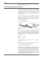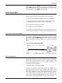
1
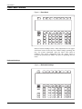
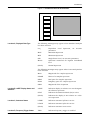
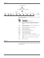
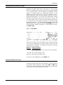
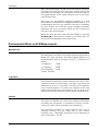
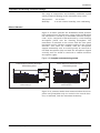
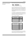
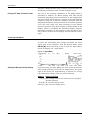
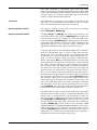
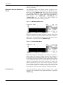
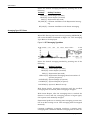
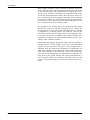
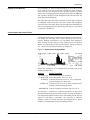
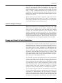
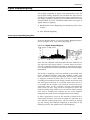
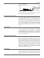
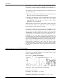
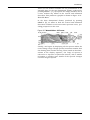
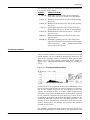
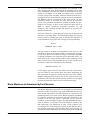
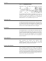
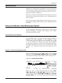
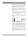
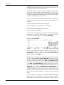
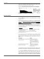
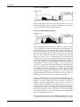
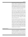
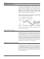
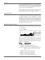
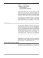
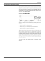
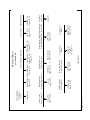
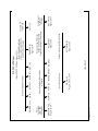
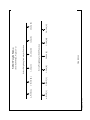
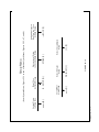
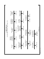
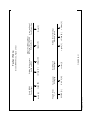
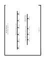
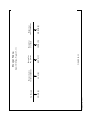
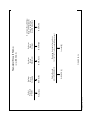
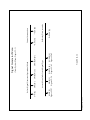
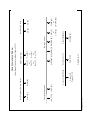
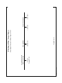
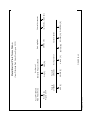
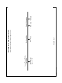
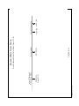
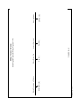
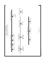
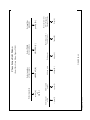
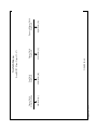
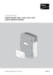
2900 MANUAL
Printer Out
Digital Out Connector
Line
Because the Centronics interface on the Model 2900 will be
connected to the hardware module, use this connector for the
printer.
This LED indicator is illuminated when the hardware module
is connected to line voltage and turned on.
This LED indicator flashes whenever data transfer between
the Model 2900 and the hardware module is taking place.
Figure 24-2 Hardware Module Rear Panel.
VOLTAGE
SEL
LARSON•DAVIS
PROVO, UT MADE IN USA
3A
ANALYZER IN
Analyzer In
Voltage Set
Power Line Connectors
24-2
1A
MONITOR LINE
Use this to connect the 2900 Centronics interface to the
hardware module using a standard Centronics interface
cable.
Set this to correspond to the local AC line voltage.
The connector on the far right of the hardware module rear
panel is for the line, or mains, connection of the hardware
module. The connector to the left of that one is designed to
power the external monitor, although it is not necessary to
use it. The monitor may be connected directly to mains. The
advantage of using this connector is that the power to the
monitor will be switched on when the 2900 is booted up.
Use of External Color Monitor for Display and Instrument Control