1
AEROFLEX GAISLER
23.4
264
LEON4-NGMP-DRAFT
Bus Controller Operation
23.4.1 Overview
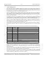
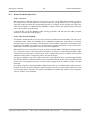
When operating as Bus Controller, the core acts as master on the MIL-STD-1553 bus, initiates and
performs transfers.
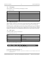
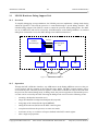
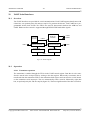
This mode works based on a scheduled transfer list concept. The software sets up in memory a
sequence of transfer descriptors and branches, data buffers for sent and received data, and an IRQ
pointer ring buffer. When the schedule is started (through a BC action register write), the core processes the list, performs the transfers one after another and writes resulting status into the transfer list
and incoming data into the corresponding buffers.
23.4.2 Timing control
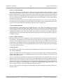
In each transfer descriptor in the schedule is a “slot time” field. If the scheduled transfer finishes
sooner than its slot time, the core will pause the remaining time before scheduling the next command.
This allows the user to accurately control the message timing during a communication frame.
If the transfer uses more than its slot time, the overshooting time will be subtracted from the following
command’s time slot. The following command may in turn borrow time from the following command
and so on. The core can keep track of up to one second of borrowed time, and will not insert pauses
again until the balance is positive, except for intermessage gaps and pauses that the standard requires.
If you wish to execute the schedule as fast as possible you can set all slot times in the schedule to zero.
If you want to group a number of transfers you can move all the slot time to the last transfer.
The schedule can be stopped or suspended by writing into the BC action register. When suspended,
the schedule’s time will still be accounted, so that the schedule timing will still be correct when the
schedule is resumed. When stopped, on the other hand, the schedule’s timers will be reset.
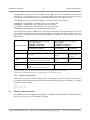
When the extsync bit is set in the schedule’s next transfer descriptor, the core will wait for a positive
edge on the external sync input before starting the command. The schedule timer and the time slot balance will then be reset and the command is started. If the sync pulse arrives before the transfer is
reached, it is stored so the command will begin immediately. The trigger memory is cleared when
stopping (but not when suspending) the schedule. Also, the trigger can be set/cleared by software
through the BC action register.
23.4.3 Bus selection
Each transfer descriptor has a bus selection bit that allows you to control on which one of the two
redundant buses (‘0’ for bus A, ‘1’ for bus B) the transfer will occur.
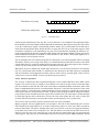
Another way to control the bus usage is through the per-RT bus swap register, which has one register
bit for each RT address. Writing a ‘1’ to a bit in the register inverts the meaning of the bus selection
bit for all transfers to the corresponding RT, so ‘0’ now means bus ‘B’ and ‘1’ means bus ‘A’. This
allows you to switch all transfers to one or a set of RT:s over to the other bus with a single register
write and without having to modify any descriptors.
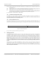
The hardware determines which bus to use by taking the exclusive-or of the bus swap register bit and
the bus selection bit. Normally it only makes sense to use one of these two methods for each RT,
either the bus selection bit is always zero and the swap register is used, or the swap register bit is
always zero and the bus selection bit is used.
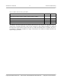
If the bus swap register is used for bus selection, the store-bus descriptor bit can be enabled to automatically update the register depending on transfer outcome. If the transfer succeeded on bus A, the
Copyright Aeroflex Gaisler AB
ESA contract: 22279/09/NL/JK Deliverable: D9
May 2013, Version: Draft-2.1