1
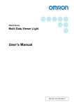
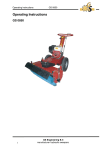
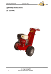
COOLMASTER CM 100 Dry Ice Blasting System Original User Manual The designations in this publication may be trademarks whose use by third parties for their own purposes could violate the rights of the owner. We have reviewed the contents of this publication to ensure consistency with the hardware and software described. Since variance cannot be precluded entirely, we cannot guarantee full consistency. However, the information in this publication is reviewed regularly and any necessary corrections are included in subsequent editions. Copyright © HaDo International GmbH HaDo International GmbH Neckar-Alb-Str. 80 D-72127 Mähringen Germany [email protected] www.hado-international.de www.coolmaster.de Subject to change without prior notice Table of contents Table of contents..................................... 3 Notes on the user manual ....................... 3 Danger instructions ................................. 3 Environmental protection notes ............... 3 Description of the functions ..................... 3 Safety instructions................................... 3 Use as prescribed ................................... 4 Failure to use as prescribed .................... 4 Warning signs ......................................... 4 Labels on the dry ice blasting system...... 6 Controls and connections........................ 6 Moving the dry ice blasting system.......... 7 Infrastructure at the workplace ................ 7 Storing the dry ice ................................... 8 Starting up the dry ice blasting system .... 8 Operating the dry ice blasting system ... 10 Transporting the dry ice blasting system11 Storing the dry ice blasting system........ 11 Maintenance instructions....................... 11 Troubleshooting .................................... 12 Technical data....................................... 14 Parts list ................................................ 14 Warranty ............................................... 15 EU Declaration of Conformity ................ 15 Type approval test................................. 15 elektro-altgeräte-register® foundation (ear) ...................................................... 15 Notes on the user manual This user manual contains basic information that must be observed when setting up, operating and maintaining the dry ice blasting system. The owner of the system, the operators and service engineers must read the user manual before starting the machine. As the owner of the dry ice blasting system, you are responsible for ensuring that the user manual is available at the place of use at all times. As the owner, you must ensure that your employees have read and fully understood the contents of the user manual. Danger instructions WARNING A thorough knowledge of the relevant part of this user manual is required before carrying out any work on or with the dry ice blasting system. All work must be carried out by appropriately trained and qualified personnel. Always take note of the danger and warning instructions and notes on precautionary measures. Environmental protection notes The dry ice blasting system is manufactured giving preference to materials and parts that can be easily separated and disposed of in an environmentally-friendly way. The owner of the machine has sole responsibility for the proper environmentally-friendly disposal of the machine, working materials, consumables and wearing parts. Please observe your national statutory provisions for waste disposal and environmental protection. Description of the functions The dry ice blasting system must be supplied with compressed air and power, and the hose and blast gun must be connected before it can be used. The dry ice blasting system is then ready for use (see "Controls and connections", Fig. 2 and Fig. 3, from page 7). To prepare the machine for blasting, first select and confirm the blasting program, select the pellet size and fill the hopper with dry ice. To start working with the blasting system, press the safety button on the blasting gun and then pull the trigger on the blasting gun. When blasting starts, the dry ice hopper for the blasting system is set in motion by a vibrating magnet in order to provide a steady supply of dry ice. The dry ice pellets drop into the processing unit, where the size of the pellets can be varied using the metering lever. The volume of ice and compressed air intensity are selected using the program settings (see item 3, Fig. 2, page 7 and Tab. 2, page 9). In this area, the dry ice pellets are prepared together with the compressed air and are controlled via a regulating valve. The mixture is transported with high acceleration through the blasting hose to the nozzle, and exits the nozzle as a bundled jet. The accelerated dry ice pellet reaches the nozzle opening at practically the speed of sound, and then bounces off the object to be cleaned. The cleaning procedure on the object thus benefits from three effects: – Thermal effect The low temperature of the dry ice makes the dirt on the object’s surface brittle. – Kinetic effect The impact of the dry ice pellet transfers pulses which fling the embrittled dirt particles away from the surface. – Sublimation effect At the point of impact, the dry ice pellets sublimate, i.e. they change directly from the solid to the gaseous state. In so doing, the gas volume expands up to 700 times. The dirt particles practically jump away from the surface. Safety instructions 3 This user manual contains notes that must be observed to guarantee your personal safety and to avoid injury or damage to equipment. They are highlighted by warning triangles and are indicated as follows according to the level of risk: Risk classification DANGER as used in this user manual means that death, severe injury or considerable damage to equipment will occur if the danger instructions are not followed. WARNING as used in this user manual means that death, severe injury or considerable damage to equipment may occur if the warning instructions are not followed. CAUTION as used in this user manual means that slight injury or damage to equipment may occur if the caution instructions are not followed. Notes on operational safety The following points MUST be observed in order to maintain operational safety: Operational safety can be guaranteed only if the system is used as prescribed and in accordance with the instructions in the user manual. The relevant employer’s liability insurance association information, guidelines and regulations should be followed when using the machine in Germany. Otherwise follow the regulations specific to your country. – BGI 515 – Personal protective equipment (PPE) – BGI 534 – Working in confined spaces – BGI 836 – Gas warning equipment – BGR 117 – Tanks, silos and confined spaces – BGR 189 – Use of protective clothing – BGR 191 – Use of foot and knee protection – BGR 195 – Use of protective gloves – BGR 500 – Operation of work equipment: chapter 2.24. section 3.7 – BGV D26 – Blasting work These brochures can also be downloaded on the Internet in PDF format at http://www.arbeitssicherheit.de. You can order a printed version from the following address: Carl Heymanns Verlag GmbH Luxemburger Str. 449, 50939 Cologne, Germany, Email: [email protected] Tel.: +49 (0)2631-801-2277 Fax: +49 (0)2631-801-2233 Make sure that the warning labels are always clearly identifiable and always easily readable. Replace any damaged warning labels. If any intervention inside the machine is required, always call out a service engineer from the manufacturer. The manufacturer will not accept liability for any damage or consequential damage that is the result of incorrect work. If particularly hazardous situations are identified during use, the machine owner must immediately notify the manufacturer in writing so that appropriate action can be taken to reduce the potential danger. Safety of users and other persons WARNING For your own safety, wear work clothes that conform to the employers’ liability insurance association guidelines (see the section on operational safety). Reduce the potential risks by not wearing scarves, chains or ties. People with long hair must wear a protective head covering. DANGER Never point the blasting gun towards yourself, other people or animals. Put up a barrier to keep unauthorised people away from the workplace. Unprotected people are exposed to considerable risks of injury from flying dry ice pellets. Never reach into the jet of dry ice while blasting. Never use the dry ice blasting system in a potentially explosive environment. If the power cable is damaged, call in a service engineer so that a new cable can be installed. WARNING During operation, some parts of the machine, such as the nozzle of the blasting gun and the dry ice filling hopper, reach very low temperatures. Risk of cryogenic burns. You should therefore wear suitable protective clothing and never take hold of the extremely cold parts with your bare hands. WARNING The recoil force of the blasting gun represents a potential danger if the blasting gun is not held firmly or if the operator is not standing safely. Wear safety boots and hold the blasting gun firmly in your hands while blasting. Use as prescribed The dry ice blasting system must only be used to remove soiling from surfaces using dry ice pellets. Use for a different or more extensive purpose is not prescribed. Use as prescribed also includes compliance with the instructions in the user manual. For the machine to operate correctly and reliably, it must have been transported, stored, set up and assembled correctly and must be operated and maintained correctly. Contact with dry ice (solid CO2 at a temperature of -78.5°C) or very cold parts of the machine can lead to cryogenic burns or frostbite. Never touch the dry ice or frozen parts of the machine, such as the nozzle, filling hopper over the processing unit and the blasting hose couplings, with your bare hands. Observe the dry ice manufacturer’s safety data sheet. Failure to use as prescribed Failure to use the machine as prescribed can result in injury or death and damage to property. The machine must NOT be used other than as prescribed. The manufacturer shall not accept any liability for any loss or damage that might occur. Use other than as prescribed includes, for example: – The use of blasting materials other than dry ice. – Impurities in the dry ice, such as metal swarf. – Uncleaned, oily compressed air. – Any mode of operation other than surface cleaning with dry ice. Warning signs DANGER Carelessness when using dry ice and the dry ice blasting system may result in serious accidents. Never point the blasting gun towards yourself, other people or animals. Dry ice pellets flying around represent a considerable risk of injury. You should therefore put up barriers to keep other people away from the work place. If the dry ice blasting system is faulty or the cable is damaged, always have it repaired by one of the manufacturer’s authorised service engineers. Always keep dry ice out of the reach of other people and animals. Never swallow dry ice. Danger of expansion in volume and cryogenic burns. WARNING 4 DANGER The dry ice sublimates at a temperature in excess of -78.5 °C: the solid CO2 changes directly to the gaseous state. The gas volume expands to 700 times its original volume. This creates high pressure that can cause sealed containers to burst. You should therefore never transport the dry ice in tightly sealed containers. DANGER The dry ice consists of solid carbon dioxide (CO2). In operation, the CO2 concentration rises rapidly and can cause breathing difficulties or even respiratory arrest in poorly ventilated, confined spaces. Always ensure adequate ventilation at the workplace. Install a CO2 warning device. Higher CO2 concentrations in the breathing air can be detected by the following symptoms: – approx. 0.5 to 1 % by volume: Bodily functions are generally not particularly affected if only inhaled for brief periods. – approx. 2 to 3 % by volume: The respiratory centre is increasingly irritated, breathing becomes more intense and the pulse rate rises. – approx. 4 to 7 % by volume: The above-mentioned difficulties become even more intense. Circulation problems occur in the brain, with feelings of dizziness, nausea and tinnitus. – approx. 8 to 10 % by volume: The above-mentioned difficulties become even more intense with the addition of cramps and loss of consciousness, shortly followed by death. – more than 10 % by volume: Death by asphyxiation occurs directly. If the CO2 warning device signals an alarm or if you identify symptoms of an increased CO2 concentration, take the following action: Immediately shut down the dry ice blasting system by switching it off at the main switch. Go out into the fresh air. Improve the fresh air supply at the workplace. 5 DANGER During cleaning, the object to be cleaned may become charged with static electricity. The electrical discharge can cause injury to people or damage to electronic components (e.g. can impair the function of heart pacemakers). Earth the object and blasting system to a common earth (see page 8). WARNING Dry ice particles may bounce off the object or detached dirt particles flying around can result in injury, particularly to the eyes. You must therefore wear safety goggles. Always wear ear defenders during blasting due to the high noise level. WARNING All parts of the machine that come into contact with dry ice reach very low temperatures. You should therefore wear suitable safety gloves to protect your hands against injury and cryogenic burns. Remove mains plug 4 Grinder settings 5 Warning and mandatory signs WARNING There is a rotating roller beneath the hopper opening. There is a risk that long hair may become caught up in the roller and pulled inside. You should therefore wear a protective hair covering. Labels on the dry ice blasting system Controls and connections Controls and connections on the dry ice blasting system The controls and connections on the dry ice blasting system are grouped ergonomically and arranged on the front and back. On the front are the connections for the blasting gun and object to be blasted. The operating and supply connections are located on the back. WARNING Detached dirt particles can be as small as the finest dust particles. Long-term exposure to such fine dust can result in diseases of the respiratory tract. You should therefore wear lightweight breathing protection, such as a protective mask. Controls and connections on the back WARNING Bouncing dry ice pellets and detached dirt particles can reach high speeds. You should therefore wear suitable clothing with long sleeves and legs. Fig. 1: Labels on the dry ice blasting system WARNING Recoil forces occur while you are using the blasting gun. Sturdy footwear is therefore essential for the operator’s stability. Wear safety boots. 3 1 TÜV type approval test 2 Rating plate Trockeneistrahlgerät IP 54 Typ: CM 100 230V, 300W, 50/60Hz Druckluftanschluss: max. 10bar SNR: CM10001 HaDo International GmbH 6 On the back (the side with the handle) are the supply connections and the controls for the dry ice blasting system: – Power supply cable – Connection for the compressed air supply – Metering lever for setting the pellet size on the processing unit The metering lever is used to set the pellet size in six stages between 0.4 mm and 3.0 mm. The metering range is divided into three coloured areas. These indicate to the operator which nozzle to use (with the same colour coding). In the red area, you can reduce the pellet size to a minimum of 0.4 mm, while in the green you can increase the size up to a maximum of 3.0 mm. – – – Power switch This lights up green when the machine is switched on and is powered with mains voltage. Liquid crystal display showing the current program with the default parameters or the parameters you have set yourself. Program selector for selecting the program or program parameters. Press the program selector to set the parameters. Connections on the front Fig. 3: Dry ice blasting system – front 1 Fig. 2: Dry ice blasting system – back 1 Connection for the compressed air supply 2 Power supply cable 3 Metering lever for setting the pellet size 4 Colour codings to indicate the nozzle size and setting range 5 Power switch with indicator lamp 6 Program selector 7 LCD display 8 Mandrel for fixing the blasting gun 9 Bracket for winding up the power cable 10 Handle for transporting the dry ice blasting system Connecting coupling for the blasting hose 2 Multipole socket for the blasting gun control cable 3 Banana jack for the earth cable – colour coded yellow/green 4 Parking brakes on the castors All the connections for the blasting hose bundle and object to be blasted are located on the front of the dry ice blasting system. – Connecting coupling for the blasting hose. The accelerated pellets are transported through the blasting hose to the blasting gun via this connection. – Multipole socket for connecting the blasting gun control cable. This cable also supplies voltage to the LEDs that light up the object to be blasted. – Banana jack for connecting the yellow/green earth cable for the object to be blasted. Controls and connections on the blasting gun The following controls can be found on the blasting gun: – Trigger for releasing the jet of dry ice – Safety button is pressed to release the trigger interlock – Control cable This is permanently connected to the blasting gun. – Blasting hose For safety reasons, this connection is designed as a screw-in connection. – Bright, white LEDs for lighting the object – Nozzle There are three different shapes with different colour codings: – Round nozzle 5.5 mm, coded green – Round nozzle 3.0 mm, coded yellow – Flat nozzle 8 x 1.8 mm, coded red The following table shows which type of nozzle can be combined with which metering lever setting. Metering lever setting in the coloured area Red Yellow Green Nozzle colour Red Yell Gre ow en yes yes yes no yes yes no no yes Tab. 1: Combinations of metering lever setting and nozzle type Moving the dry ice blasting system The dry ice blasting system moves on four castors. The two large castors are mounted on ball bearings, while the two small castors at the front rotate and can be locked with the parking brake (item 4 in Fig. 3). CAUTION Do not tilt the dry ice blasting system sideways by more than 20°. Risk of tipping. When you push the dry ice blasting system, hold it firmly by the handle while moving on a slope. The weight is roughly 36 kg. Do not sit on the dry ice blasting system and never place heavy objects on it. Infrastructure at the workplace Fig. 4: Controls and connections on the blasting gun 1 2 3 4 5 6 Trigger Safety button Control cable, fixed Blasting hose, fixed 2 LEDs, white Nozzle 7 Conditions at the workplace Make sure that the workplace is well-ventilated, and that the ground surface is as level as possible and free of obstructions. DANGER There is a risk of electric shock if the following rules are ignored during electrical installation. The socket for the power supply connection must be installed by a trained electrician to DIN VDE 0100 (IEC 60364-1:2005). DIN VDE 0100-704:2007 (IEC 60364-7-704:2005), in particular, should be taken into account when the dry ice blasting system is used on sites with TT, TN-S or IT circuits. The socket must be protected by a residual current device (RCD) tripped by a 30 mA current differential. Only connect the dry ice blasting system at sockets with a protective earth contact and RCD. Compressed air supply The quality of the compressed air has a significant influence on the cleaning effect of the compressed air jet, and should conform to at least DIN ISO 8573, class 3. This means that it should be largely free of oil, dirt and foreign particles and that the relative atmospheric humidity should not exceed 5 %. If the quality of the compressed air is impaired, suitable oil and water separators must be integrated. WARNING If the supply pressure is greater than 1MPa (10 bar) there is a risk that components in the dry ice blasting system will be damaged or destroyed. Make sure that the supply pressure does not exceed 1 MPa (10 bar). Use a pressure-reducing valve if necessary. Storing the dry ice The quality of the dry ice has a significant effect on the cleaning effect of the dry ice jet. Store the dry ice in a speciallydesigned thermal container in which any excess pressure can be dissipated. DANGER Do not used tightly-sealed containers. Risk of bursting due to excess pressure when the CO2 sublimates. Make sure that the dry ice is free of dirt and foreign particles. WARNING Contaminated dry ice or other blasting media will invalidate the manufacturer’s warranty. Only use dry ice as the blasting medium. PLEASE NOTE Only use dry ice with a low moisture content. The dry ice will clump together faster if the moisture content is higher. Only store the dry ice for a few days in the thermal container. The blasting quality will be impaired after a longer storage time. Starting up the dry ice blasting system Set up the dry ice blasting system Set up the dry ice blasting system on a surface that is as flat and horizontal as possible. Lock the parking brake on the front castors (item 4 in Fig. 3) Select a nozzle There is a nozzle holder for four nozzles on the front of the dry ice blasting system (item 2 in Fig. 5). Open the cover flap (item 4 in Fig. 5) and remove a suitable nozzle (item 1 in Fig. 5). Screw the nozzle into the blasting gun (item 6 in Fig. 4). DANGER Note, in particular, the safety instructions about the workplace infrastructure. Connect the blasting hose bundle For safety reasons, the blasting gun is permanently screwed to the blasting hose. WARNING The maximum blasting hose length must not exceed 9 m. This will ensure that the dry ice jet can be interrupted within one second when the trigger on the blasting gun is released. A blasting hose must not be used if it is damaged. Before connecting, check the blasting hose for bends, cracks and breaks. Attach the blasting gun to the mandrel (item 8 in Fig. 2) on the hose winding bracket of the dry ice blasting system. Insert the blasting hose into the coupling (item 1 in Fig. 3) on the front of the dry ice blasting system. Connect the control cable to the multipole socket (item 2 in Fig. 3). Make sure that the white marks on the plug and socket are lined up. Earth the object to be blasted DANGER During dry ice blasting, the metallic object to be blasted will discharge static electricity if it is not earthed. Clip the earthing cable provided to the object to be blasted. Plug the banana plug of the earthing cable into the yellow-green banana jack on the dry ice blasting system. Make sure that the earth connection does not become detached during the blasting process. 8 Fig. 5: Nozzle holder for four nozzles 1 2 3 4 Nozzle Nozzle holder for four nozzles Filling hopper for dry ice Cover flap Connect the dry ice blasting system to the compressed air supply The supply pressure for the dry ice blasting system is between 0.05 MPa and 1 MPa (0.5 bar and 10 bar). You will find the compressed air specification in the "Infrastructure at the workplace“ section. DANGER The supply pressure must never exceed 1 MPa (10 bar), otherwise important components of the dry ice blasting system will be damaged. Before connecting the compressed air hose, check it for bends, cracks and bulges. Always replace the compressed air hose if it is faulty. WARNING When the input pressure is high, there are powerful mechanical forces acting on the hose. Always wear safety goggles and ear defenders when you connect it. Hold the hose coupling firmly so that it cannot be dashed out of your hand when you attach it to the coupling plug on the dry ice blasting system. Check that the hose coupling has engaged correctly. Connect the dry ice blasting system to the power supply The connecting cable is designed for use on building sites. Always use the same type of cable for cable extensions. Check the connecting cable for bends, breaks or abrasions. DANGER Never connect a faulty cable to the power supply. Call out a manufacturer’s service engineer to have a faulty connecting cable replaced. Make sure that the main power supply is installed as described in the "Infrastructure at the workplace" section. Setting the pellet size for the dry ice Use the metering lever (item 3 in Fig. 2) to set the dry ice pellet size. Note that the nozzle that you use will depend on the pellet size setting (see the "Controls and connections on the blasting gun“ section). Note that program no. 7 is not suitable for the red flat nozzle (see Fig. 6). For the USER PROG. setting, note that you must not select a volume of ice > 25 kg/h for flat nozzles. PLEASE NOTE In individual cases blockages may occur when the blasting pressure is < 0.5 bar For program 1, for example, blasting is carried out with a pressure of 0.5 bar. The dry ice usage rate is 4.0 kg/h. Turn the program selector (item 6 in Fig. 2) until the highlighted field in the main menu is on the required program. Press the program selector once to confirm your selection. The selected program appears in the LCD display with its preset parameters. Turn clockwise: The highlighted field jumps to the ice volume usage field Select the pressure display field. Press the program selector. The pressure is shown in large type in the middle of the LCD display. Turn the program selector until the required pressure value is displayed. Press the program selector to confirm the displayed value. Repeat the procedure in the same way to set the ice usage rate. Once you have entered the data, the menu to exit the program appears. Turn the program selector to move the highlighted field to YES and press the program selector. This returns you to the main menu. Select a nozzle Switch on the dry ice blasting system Switch on at the main switch (item4 in Fig. 2). The indicator lamp in the power switch lights up green. Press the program selector again to return to the main menu. Select a dry ice blasting program Set the blasting parameters in the user program When you switch on at the main switch, the main menu appears on the LCD panel. – There are three different nozzles for the dry ice blasting system: – Flat nozzle with an opening crosssection of 8 mm x 1.8 mm. This nozzle is colour coded red and is suitable for small pellets. You can also define the parameters for a blasting program yourself. Turn the program selector until the highlighted field in the main menu is on USER PROG. Press the program selector. The USER PROG. menu appears on the LCD display. Fig. 6: Flat nozzle – colour coded red You can select one of seven programs with preset parameters or the operator can select a program and enter the parameters himself. The following table shows the programs with the preset parameters and the program with variable “Blasting pressure" and “Volume of ice" parameters. Program 1 2 3 4 5 6 7 USER PROGR. Blasting pressure [bar] 0,5 1,0 2,0 3,0 4,0 6,0 9,9 0-9,999 Volume of ice [kg/h] 4 8 12 16 20 27 35 * 0-35 * Tab. 2: Dry ice blasting programs *) The maximum volume of ice for the flat nozzle is 25 kg/h. Larger ice volumes will clog the flat nozzle. – Round nozzle with an opening diameter of 3.0 mm. This nozzle is colour coded yellow. Field 1: Blasting pressure min. 0.1 bar, max. 9.999 bar PLEASE NOTE When you make the setting, remember that the input pressure is always higher than the selected blasting pressure. Field 2: Ice usage rate min. 2.5 kg/h, max. 35 kg/h Use the program selector to select the input field: – Turn anticlockwise: The highlighted field jumps to the pressure display field 9 Fig. 7: Round nozzle 3 mm – colour coded yellow – Round nozzle with an opening diameter of 5.5 mm. This nozzle is colour coded green and is suitable for pellets up to a maximum size of 3 mm. Fig. 8: Round nozzle 5.5 mm – colour coded green Select the required nozzle and screw it into the opening in the blasting gun (see Fig. 4) Operating the dry ice blasting system Start up the dry ice blasting system as described in the "Starting up the dry ice blasting system" section. DANGER Observe the safety and danger notes in the user manual. PLEASE NOTE The nozzle can become clogged if the wrong combination of nozzle type and pellet size is used. Check that the combination of nozzle type and pellet size setting is permitted (see Tab. 1). Select the blasting program that you want to use for the cleaning process (see Tab. 1). Note that program no. 7 is not suitable for the flat nozzle. For the USER PROG. setting, note that you must not select a volume of ice > 25 kg/h for flat nozzles. Load the filling hopper with dry ice DANGER Risk of cryogenic burns if the skin comes into contact with dry ice. Wear protective gloves to protect yourself against cryogenic burns. Take hold of the recessed handle (item 1 in Fig. 9) and open the cover flap (item 3 in Fig. 9) over the filling hopper (item 2 in Fig. 9). Use the scoop provided to load the filling hopper with dry ice. Then close the cover flap so that no dirt particles can enter the filling hopper. Safety measures before blasting Check that the parking brakes are applied on the front castors (item 4 in Fig. 3). DANGER Metal objects can become charged with static electricity during the blasting process. Make sure that metal objects to be blasted are connected to the blasting system via the earthing cable. DANGER During blasting, there is an increased risk of injury from flying dry ice pellets and detached substrate. Put up a barrier around the workplace to prevent access by unauthorised persons. Wear your personal protective equipment. Dry ice blasting process DANGER Risk of asphyxiation due to the increased CO2 concentration. Make sure that your workplace is well ventilated. Set up a CO2 warning device with visible and audible signals. Arrange for another person look out for the warning signals and issue an alarm if the confined and unclear working conditions make this necessary. This second person should also wear personal protective equipment for their own safety. Make sure that visual contact or another means of communicating with the blasting system operator is guaranteed (BGV D26). Check that you have a firm foothold on the ground surface. Point the nozzle of the blasting gun onto the object to be blasted. Press the safety button (item 1in Fig. 10on the blasting gun. Press the trigger (item2 in Fig. 10) on the blasting gun. Fig. 9: Loading the filling hopper with dry ice 1 2 3 Recessed handle Filling hopper Cover flap 10 Fig. 10: Actuating the blasting gun 1 2 – – Safety button Trigger DANGER If the blasting process creates potentially harmful dust particles, such as mould spores or other toxins, you must wear a breathing apparatus with a tightly-fitting face mask and eye protection. If dust extraction systems are used there is a risk of explosion when working alternately with parts containing iron and light metal parts. You should therefore clean the dust extraction systems when the object to be blasted changes and the material properties of the different objects change. End the dry ice blasting process Release the trigger (item 2 in Fig. 10). The dry ice jet stops immediately. Attach the blasting gun to the mandrel provided (item 8 in Fig. 2). PLEASE NOTE Do not interrupt the dry ice blasting process for long periods as this can cause the dry ice to form clumps. Empty the filling hopper (item 2 in Fig. 9) if you intend to interrupt the blasting process for a long time. Shut down the dry ice blasting system DANGER Note the safety instructions for operating the dry ice blasting system. Open the cover flap (item 3 in Fig. 9) over the filling hopper (item 2 in Fig. 9). Use the scoop to remove the rest of the dry ice as far as possible. Remove any small residue in the filling hopper by actuating the blasting gun again. Now switch off the compressed air supply to the dry ice blasting system. WARNING A compressed air hose that is under high pressure when the coupling is detached can whip back, slip out of the hand and cause injuries. There is also the risk of ear blast injury. You should therefore never detach the compressed air hose from the coupling on the dry ice blasting system while the blasting system is still pressurised. Actuate the blasting gun again until the pressure in the dry ice blasting system has dissipated. Attach the blasting gun to the mandrel provided (item 8 in Fig. 2). Switch off the dry ice blasting system at the main switch (item 4 in Fig. 2). Unplug the main connector from the socket. Wind the power supply cable around the winding bracket (item 9 in Fig. 2). Detach the blasting hose bundle from the connections on the dry ice blasting system (items 1 and 2 in Fig. 3). Transporting the dry ice blasting system DANGER There is a risk of asphyxiation from the increased CO2 concentration when the dry ice remaining in the filling hopper sublimates. This applies particularly in confined spaces, such as a small transporter vehicle. Make sure that the dry ice blasting system is completely empty (see "Shut down the dry ice blasting system", page 10). Follow the procedure described below when transporting the dry ice blasting system in a vehicle: Apply the parking brakes of the small castors as soon as you have placed the dry ice blasting system on the loading surface. Use suitable straps to secure the dry ice blasting system on the loading surface. Follow the guidelines issued by the employers’ liability association for transport and traffic: BGI 649 “Securing loads on vehicles". Maintenance instructions Before each use: Check the housing, the power cable and the hose bundle for damage. Check the hopper for dirt. Make sure that the nozzle is free from foreign particles. Every 500 h / every six months Check the tension of the chain. Clean the interior space. Check the fixings of the power cable in the interior space. Check the hose fittings for tightness. Check the covers of the rolling bearings. Check the grinder setting for ease of use. Check that the colour coating of the nozzle thread is still present. Every 1000 h / every year Grease the chain with Klüberoil 4 UH1- 15. Every two years Replace the blasting hose bundle. Storing the dry ice blasting system Always store the dry ice blasting system inside in a dry area. Observe the accident prevention regulations when you store the dry ice blasting system. It weighs roughly 36 kg. 11 Troubleshooting Description of the fault Power switch switched on: Green indicator lamp does not light up. Possible causes Power connector not plugged into the socket. Cable break, the plug is not making contact. The RCD has tripped. The RCD trips several times. To eliminate Plug the power connector into the socket. By whom Operator Check the power cable for bends, particularly at the connector. Activate the RCD. Check the RCD. Service engineer Operator Service engineer Service engineer Operator Check the machine for earth faults. Trigger on the blasting gun is actuated: No compressed air blast The machine is not connected to the compressed air supply. The compressed air supply is interrupted. Very oily compressed air has clogged the filter in the maintenance unit. The plug-in connection for the control cable is interrupted. The control cable is faulty. The blasting hose is clogged. Connect the machine to the compressed air supply. Check that the push-fit couplings are seated firmly. Check the pressure of the compressed air compressor. Clean the filter in the maintenance unit. Check that the plug-in connection for the control cable on the front of the machine is seated firmly. Check the control cable for bends or breaks, particularly at the connector. Replace the blasting hose bundle if necessary. Check the blasting hose for bends. Replace the blasting hose bundle if necessary. Detach the blasting hose from the coupling and investigate whether there are foreign bodies or clumped dry ice pellets clogging the hose. Wait until the clumped dry ice has evaporated and remove any foreign bodies. Screw the blasting hose to the coupling once more and actuate the blasting gun. Operator Operator Service engineer Operator Operator Operator Operator DANGER Never look into the opening in the nozzle or the blasting gun while you pull the trigger. Unscrew the nozzle and check whether there are foreign bodies or clumped dry ice pellets clogging the blasting gun or nozzle. Wait until the clumped dry ice has evaporated and remove any foreign bodies. Briefly pull the trigger of the blasting gun to eliminate the clogging, then screw in the nozzle once more. The nozzle is clogged. Operator DANGER Trigger on the blasting gun is actuated: No dry ice jet The filling hopper is empty. The dry ice in the filling hopper has clumped together. Never look into the opening in the nozzle or the blasting gun while you pull the trigger. Fill the filling hopper with dry ice. Use the scoop to remove the dry ice and allow the rest to evaporate. Refill with fresh dry ice. Operator Operator WARNING Never use sharp metal objects in the filling opening of the processing unit to attempt to break up the clumped pellets. This could damage the metering roller. Detach the blasting hose from the coupling and investigate whether there are foreign bodies or clumped dry ice pellets clogging the hose. Wait until the clumped dry ice has evaporated and remove any foreign bodies. The blasting hose is clogged. Operator DANGER Never look into the opening in the nozzle or the blasting gun while you pull the trigger. Check whether the nozzle’s colour coding represents a permitted combination with the metering lever setting. Either use another nozzle, correct the metering lever setting or change the blasting program. The nozzle is clogged. 12 Operator DANGER Never look into the opening in the nozzle or the blasting gun while you pull the trigger. Unscrew the nozzle and check whether there are foreign bodies or clumped dry ice pellets clogging the blasting gun or nozzle. Wait until the clumped dry ice has evaporated and remove any foreign bodies. Operator DANGER The processing unit is blocked. The motor circuit-breaker has tripped because the temperature is too high. The blockage disappears after a short time. The processing unit is blocked for a longer period. Device clogs easily: Incorrect parameter setting Warning notes on the LCD display: Overpressure Faults in the dry ice blasting system Never look into the opening in the nozzle or the blasting gun while you pull the trigger. If you had pulled the blasting gun trigger, release the trigger and then pull it again. Check the dry ice for impurities, such as metal parts. Operator Operator Call a service engineer if repairs are needed. Service engineer Operator The vibrator above the processing unit is faulty. The volume of ice is greater than 25 kg when using the flat nozzle. The operating pressure is smaller than 0.5 bar. The degree of grinding is greater than stage 2 when using the flat nozzle. The supply pressure is greater than 1.0 MPa (10 bar). Replace the faulty vibrator. Make sure that the pressure of the compressed air supply does not exceed 1.0 MPa (10 bar). Operator The processing unit is switched off due to overloading. Wait for a short time. Operator 13 Unscrew the nozzle and blow out the blasting hose at high pressure. DANGER Never look into the opening in the nozzle or the blasting gun while you pull the trigger. Technical data Electrical ratings Supply voltage Nominal apparent power Fuse protection for the socket Residual current device (RCD) Degree of protection 230 VAC, 50 Hz 300 W 1 x 16 A 30 mA IP54 Pneumatic ratings Supply pressure pvmin pvmax Operating pressure pbmin pbmax Compressed air connection Compressed air consumption Compressed air specification 0.05 MPa (0.5 bar) 1.0 MPa (10 bar) 0.05 MPa (0.5 bar) 1.0 MPa (10 bar) ½" hose connector 200 l/min … 1100 l/min At least class 3, ISO 8573-1 Performance data Dry ice supply Capacity of the dry ice container Pellet size Dry ice usage rate Max. 3 mm pellets 6 kg 0.4 mm … 3.0 mm, variable in 6 stages 4 kg/h … 35 kg/h Dimensions and weight Length Width Height Weight 480 mm 320 mm 990 mm approx. 36 kg Noise emissions Max. noise emissions 50 dB(A) … 100 dB(A) 14 Warranty EU Declaration of Conformity We guarantee that, if used as agreed, the products will fulfil the contractually defined specifications and functions and conform to the recognised state of the art. The product described below: The warranty is limited to material, manufacturing and processing defects. The warranty also excludes damage that is caused by negligence, incorrect handling by the user or overloading or the normal natural wear and tear. We shall not accept any liability for properties or for any warranted item unless it is agreed separately in writing, expressly noting the relevant assurance of properties or warranted item. of the manufacturer: Dry ice blasting system Type: CM 100 Item no. 060500 HaDo International GmbH Neckar-Alb-Str. 80 D-72127 Mähringen complies with the regulations and standards of the EU Declaration of Conformity supplied with it. Type approval test The warranty commitment shall end 12 (twelve) months after delivery to the customer. A warranty commitment for supplementary performance claims, replacement deliveries or replacement services after such supplementary performance, replacement delivery or replacement service has been carried out shall exist up to the end of the resulting residual term arising from the warranty period specified under sentence 1. However the warranty shall expire early if the customer/user attempts to make repairs or other changes to the contractual object without prior agreement with us. The machine must be operated as described in this user manual. The user manual is part of the warranty provisions. The manufacturer’s liability with respect to safety as defined by the CE mark shall lapse if The dry ice blasting system has been type approval tested by the TÜV. Dry ice blasting system IP54 Type: CM 100 VAC: 230 V, 300 W, 50/60 Hz Compressed air connection: max. 10 bar HaDo International GmbH Neckar-Alb-Str. 80 D-72127 Mähringen elektro-altgeräte-register® foundation (ear) This product is registered in accordance with the German Waste Electrical Equipment Act WEEE and may be returned to the manufacturer for environmentally responsible disposal. – genuine parts are not replaced with genuine parts, – repairs were inexpertly made by the purchaser, – repairs were inexpertly made due to the lack of special equipment. – Wearing parts such as nozzles and hoses are not covered by the warranty. To claim under the warranty, please take the machine, with accessories and proof of purchase, to TQ-Systems GmbH or an authorised customer service centre. 15 16 Copyright © HaDo International GmbH Subject to change without prior notice HaDo International GmbH Neckar-Alb-Str. 80 D-72127 Mähringen Germany [email protected] www.hado-international.de www.coolmaster.de 17