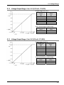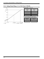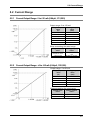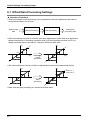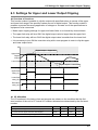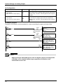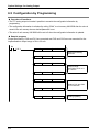
1
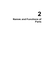
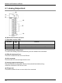
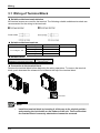
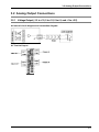
PROGRAMMABLE CONTROLLER FP7 Analog Output Unit User's Manual WUME-FP7AOH-01 2013.3 panasonic.net/id/pidsx/global Safety Precautions Observe the following notices to ensure personal safety or to prevent accidents. To ensure that you use this product correctly, read this User’s Manual thoroughly before use. Make sure that you fully understand the product and information on safety. This manual uses two safety flags to indicate different levels of danger. WARNING If critical situations that could lead to user’s death or serious injury is assumed by mishandling of the product. -Always take precautions to ensure the overall safety of your system, so that the whole system remains safe in the event of failure of this product or other external factor. -Do not use this product in areas with inflammable gas. It could lead to an explosion. -Exposing this product to excessive heat or open flames could cause damage to the lithium battery or other electronic parts. CAUTION If critical situations that could lead to user’s injury or only property damage is assumed by mishandling of the product. -To prevent excessive exothermic heat or smoke generation, use this product at the values less than the maximum of the characteristics and performance that are assured in these specifications. -Do not dismantle or remodel the product. It could cause excessive exothermic heat or smoke generation. -Do not touch the terminal while turning on electricity. It could lead to an electric shock. -Use the external devices to function the emergency stop and interlock circuit. -Connect the wires or connectors securely. The loose connection could cause excessive exothermic heat or smoke generation. -Do not allow foreign matters such as liquid, flammable materials, metals to go into the inside of the product. It could cause excessive exothermic heat or smoke generation. -Do not undertake construction (such as connection and disconnection) while the power supply is on. It could lead to an electric shock. Copyright / Trademarks -This manual and its contents are copyrighted. -You may not copy this manual, in whole or part, without written consent of Panasonic Industrial Devices SUNX Co., Ltd. -Windows is a registered trademark of Microsoft Corporation in the United States and other countries. -All other company names and product names are trademarks or registered trademarks of their respective owners. PLC_ORG Introduction Thank you for buying a Panasonic product. Before you use the product, please carefully read the installation instructions and the users manual, and understand their contents in detail to use the product properly. Types of Manual • There are different types of users manual for the FP7 series, as listed below. Please refer to a relevant manual for the unit and purpose of your use. • The manuals can be downloaded on our website: http://industrial.panasonic.com/ac/e/dl_center/manual/ . Unit name or purpose of use Manual name Manual code FP7 Power Supply Unit FP7 CPU Unit Users Manual (Hardware) WUME-FP7CPUH Instructions for Built-in COM Port FP7 Extension (Communication) Cassette FP7 CPU Unit Users Manual (COM Port Communication) WUME- FP7COM Instructions for Built-in LAN Port FP7 CPU Unit Users Manual (LAN Port Communication) WUME-FP7LAN FP7 Digital Input/Output Unit Users Manual WUME-FP7DIO FP7 CPU Unit FP7 Digital Input/Output Unit FP7 Analog Input Unit FP7 Analog Input Unit Users Manual WUME-FP7AIH FP7 Analog Output Unit FP7 Analog Output Unit Users Manual WUME-FP7AOH FP7 Positioning Unit FP7 Positioning Unit Users Manual WUME-FP7POSP PHLS System PHLS System Users Manual WUME-PHLS Programming Software FPWIN GR7 FPWIN GR7 Introduction Guidance WUME-FPWINGR7 Table of Contents Table of Contents 1. Unit Functions and Restrictions........................................ 1-1 1.1 Unit Functions and Operation................................................................. 1-2 1.2 Basic Operation of Analog Output Processing ....................................... 1-3 1.2.1 1.3 Analog Output Processing.......................................................................1-3 Restrictions on Units Combination ......................................................... 1-4 1.3.1 Limitations on the Power Consumption...................................................1-4 2. Names and Functions of Parts .......................................... 2-1 2.1 Analog Output Unit ................................................................................. 2-2 3. Wiring ................................................................................... 3-1 3.1 Wiring of Terminal Block ........................................................................ 3-2 3.2 Analog Output Connections ................................................................... 3-3 3.2.1 Voltage Output (-10 to +10, 0 to +10, 0 to +5, and +1 to +5 V) .............3-3 3.2.2 Current Output (0 to +20 and +4 to +20 mA) ..........................................3-4 4. Unit Settings and Data Writing .......................................... 4-1 4.1 4.2 Confirming the I/O Number Allocations and First Word Number............ 4-2 4.1.1 Occupied I/O Area and I/O Allocations ...................................................4-2 4.1.2 Confirming the I/O Number Allocations...................................................4-3 Configuration Settings ............................................................................ 4-4 4.2.1 ii Configuration of Analog Output Unit .......................................................4-4 Table of Contents 4.2.2 Unit Setting and Conversion Processing Time .......................................4-6 4.3 Writing Analog Output Data .................................................................... 4-7 4.4 Timing Chart of Output Processing......................................................... 4-8 5. Conversion Characteristics of Analog Output .................5-1 5.1 5.2 Voltage Range ........................................................................................ 5-2 5.1.1 Voltage Output Range: -10 to +10 V (0.32 mV, 1/62,500)......................5-2 5.1.2 Voltage Output Range: 0 to +10 V (0.32 mV, 1/31,250) .........................5-3 5.1.3 Voltage Output Range: 0 to +5 V (0.16 mV, 1/31,250) ...........................5-3 5.1.4 Voltage Output Range: +1 to +5 V (0.16 mV, 1/25,000).........................5-4 Current Range ........................................................................................ 5-5 5.2.1 Current Output Range: 0 to +20 mA (0.64μA, 1/31,250) ........................5-5 5.2.2 Current Output Range: +4 to +20 mA (0.64μA, 1/25,000) ......................5-5 6. Option Settings for Analog Output ....................................6-1 6.1 Offset/Gain Processing Settings............................................................. 6-2 6.2 Scale Conversion Settings...................................................................... 6-4 6.3 Settings for Upper and Lower Output Clipping ....................................... 6-5 6.4 Analog Output Hold while in PROG. Mode............................................. 6-7 6.5 Configuration by Programming ............................................................... 6-8 7. What to Do If an Error Occurs ............................................7-1 7.1 What to Do If an Error Occurs ................................................................ 7-2 7.1.1 Unstable Analog Output Value................................................................7-2 7.1.2 Unchanged Analog Output Value ...........................................................7-2 iii Table of Contents 8. Specifications...................................................................... 8-1 8.1 Specifications ......................................................................................... 8-2 8.2 List of I/O Allocations.............................................................................. 8-4 8.3 List of Unit Memory ................................................................................ 8-5 8.4 iv 8.3.1 List of Unit Memory Numbers..................................................................8-5 8.3.2 List of Unit Memory Specifications in Detail ............................................8-6 Dimensions............................................................................................. 8-8 1 Unit Functions and Restrictions Unit Functions and Restrictions 1.1 Unit Functions and Operation Features of analog output unit The analog output unit converts its internal data into analog values to be output to inverters or other analog-driven equipment. • Equipped with six types of output ranges (i.e., voltage ranges of -10 to +10, 0 to +10, 0 to +5, and +1 to +5 and current ranges of 0 to +20 and +4 to +20 mA). Analog output unit: 4 channels • A D/A conversion processing speed is as high as 25 μs/channel. • Converts set digital values into analog data with up to 16 bit in a resolution range of 1/25,000 to 1/62,500. 1-2 1.2 Basic Operation of Analog Output Processing 1.2 Basic Operation of Analog Output Processing 1.2.1 Analog Output Processing Analog output is processed as explained below. Operation of analog output unit (1) Writing digital data A user program is used to write digital data to the output relay area (WY) on a channel-bychannel basis so that the digital data will be output in analog form. (2) Analog conversion processing Data written to the unit is converted to an analog value in sequence automatically. (3) Output to analog-driven equipment Converted analog values are output to inverters or other analog-driven equipment. (1) (2) (3) V or I t Option settings The following option setting functions are provided for analog output processing. Any of the option setting functions can be set, if necessary, by writing the function to the unit memory (UM) by using the configuration menu of the FPWIN GR7 or a user program. • Offset/Gain processing • Scale conversion • Upper and lower output clipping • Analog output hold while in PROG. mode 1-3 Unit Functions and Restrictions 1.3 Restrictions on Units Combination 1.3.1 Limitations on the Power Consumption The FP7 analog output unit has the following internal current consumption. When the system is configured, the other units being used should be taken into consideration, and a power supply unit with a sufficient capacity should be used. Name Product no. Current consumption FP7 analog output unit AFP7DA4H 250 mA or less 1-4 2 Names and Functions of Parts Names and Functions of Parts 2.1 Analog Output Unit Names and functions of parts (1) Operation monitor LEDs LED Name - LED color Blue Contents Lit when the CPU unit is turned on. ERROR Red Lit if the configuration settings are beyond the allowable range. ALARM Red Lit if the hardware has an error. (2) Terminal block release lever To remove the analog output terminal block, push the release lever downward. (3) DIN rail attachment lever This lever is used to fix the unit to the DIN rail. (4) Unit connector Connects with I/O units and high-function units. (5) Analog output terminal block The terminal block is removable. Remove the terminal block before wiring. Solderless terminals for M3 can be used. (6) Fixing hook This hook is used to fix two or more units to be connected. 2-2 3 Wiring Wiring 3.1 Wiring of Terminal Block Suitable solderless terminals/wires M3 terminal screws are used for the terminal. The following suitable solderless terminals are recommended for the wiring to the terminals Suitable solderless terminals Manufacturer Shape Part no. Suitable wires 1.25-MS3 1.25-B3A 2-MS3 2-N3A 0.25 to 1.65 mm 2 J.S.T. Mfg Co., Ltd. Round type Fork type Round type Fork type 1.04 to 2.63 mm 2 Suitable wires Suitable wires 2 Tightening torque 2 AWG22 to 14 (0.3 mm to 2.0 mm ) 0.5 to 0.6 N·m Connection to the terminal block Remove the terminal block before beginning the wiring operations. To remove the terminal block, push downward the release lever located at the top of the terminal block. Lock button <Bottom of unit> NOTE • 3-2 Install the terminal block by inserting it all the way to its original position and pressing the lock button on the bottom of the unit. Then confirm that the terminal block is securely attached and cannot be removed. 3.2 Analog Output Connections 3.2 Analog Output Connections 3.2.1 Voltage Output (-10 to +10, 0 to +10, 0 to +5, and +1 to +5 V) Internal circuit diagram and connection diagram Terminal layout 3-3 Wiring 3.2.2 Current Output (0 to +20 and +4 to +20 mA) Internal circuit diagram and connection diagram Terminal layout NOTES 3-4 • Use double-core twisted-pair shielded wires for analog output signals. • Ground the shielding of the shielded wire on the load equipment side. However, depending on the conditions of the external noise, it may be better to ground the shielding externally or not to ground the shielding. • Do not place the analog output wiring close to AC lines, high-tension lines, or load lines other than PLC wires or bundle the analog output and other wires together. • The NC terminals of the analog output terminal block are unused. Do not use these terminals to relay wires because the terminals include those connected internally. 4 Unit Settings and Data Writing Unit Settings and Data Writing 4.1 Confirming the I/O Number Allocations and First Word Number 4.1.1 Occupied I/O Area and I/O Allocations In the FP7, digital data for analog output is allocated to the external output relay area and processed. Furthermore, control I/O signals are allocated to the FP7 to process errors and clip upper and lower output limits. Input contact Address CH1 CH2 X0 X10 X3 to XF X12 X21 WX2 X2 X20 X11 WX1 WX0 X1 CH3 X13 to X1F X22 WX3 CH0 X23 to X2F Name Description X30 Error flag Turns ON when an error is detected. X31 Upper limit of upper and lower output clipping Turns ON when the output exceeds the upper limit of output clipping, provided that the upper and lower limit function is active. X32 Lower limit of upper and lower output clipping Turns ON when the output drops below the lower limit of output clipping, provided that the upper and lower limit function is active. X33 to X3F Not used Do not use. Output contact Address CH1 CH2 CH0 CH3 Name Description Y40 to Y4F WY6 Y20 to Y2F WY4 Y0 to YF WY2 WY0 Set a digital value corresponding to the analog output. Y60 to Y6F D/A conversion data (16 bits) <Voltage range> -10 to +10 V: -31,250 to +31,250 0 to +10 or 0 to +5 V: 0 to +31,250 +1 to +5 V: 0 to +25,000 <Current range> 0 to +20 mA: 0 to +31,250 +4 to +20 mA: 0 to +25,000 * Apply a digital value within the set scale if scale conversion is set. Y11 to Y1F Y31 to Y3F Y70 Y71 to Y7F Not used WY7 Y50 WY5 Y30 WY3 WY1 Y10 Upper and lower output clipping Function execution relay Y51 to Y5F The upper and lower output limit clipping function is executed with the relay turned ON. With the relay turned OFF, the upper limit flag (Xn1) for upper and lower output clipping limits and the lower limit flag (Xn2) for upper and lower output clipping limits are turned OFF. Do not use. Note 1) The I/O numbers in the tables above show offset addresses. I/O numbers actually allocated are based on the first word number allocated to the unit. Example) If the first word number is 10, the D/A conversion data on CH0 and the error flag will be WY10 and X100, respectively. 4-2 4.1 Confirming the I/O Number Allocations and First Word Number 4.1.2 Confirming the I/O Number Allocations I/O numbers and base word numbers are always necessary when writing programs. Always check to see if the numbers match the design. I/O numbers allocated are determined by the first word number. Allocations to unit Take the following procedure to set the first word number. PROCEDURE 1. Select “Options” → “FP7 Configuration” from the menu bar. 2. Select “I/O Map” from the field. 3. Double-click the target slot where the operating unit is to be inserted. 4. Select “Analog I/O” and “Output Unit” in the unit selection field. 5. Press the [OK] button. The first word number specified is set. 4-3 Unit Settings and Data Writing 4.2 Configuration Settings 4.2.1 Configuration of Analog Output Unit Use the FPWIN GR7 configuration menu to make analog output unit settings, such as output range, offset, and gain settings. Setting method The following steps are described on the condition that the analog output unit has been already allocated on the I/O map. PROCEDURE 1. Select “Options” → “FP7 Configuration” from the menu bar. 2. Select “I/O Map” from the field. 3. Select the slot where the analog output unit is registered and press the [Set details] button. The “Analog unit settings” dialog box is displayed. 4. Select the output processing and range setting. Select option setting as required. 5. Press the [OK] button. The set value will become effective when the set value is downloaded together with a corresponding program as a project. 4-4 4.2 Configuration Settings Settings Group Basic setting items (per channel) Setting item Default Output processing Execute/Not execute Execute Range setting -10 to +10 V 0 to +10 V 0 to +5 V +1 to +5 V 0 to +20 mA +4 to +20 mA -10 to +10 V Upper and lower output clipping limits Execute/Not execute Not execute Upper limit -32,500 to +32,500 0 Lower limit -32,500 to +32,500 0 Execute/Not execute Not execute Max. value -30,000 to +30,000 10000 Min. value -30,000 to +30,000 0 Execute/Not execute Not execute Scale conversion Option setting items (per channel) Settings Offset/Gain processing Offset value -3,000 to +3,000 0 Gain value +9,000 to +11,000 10000 Non-hold/Current value hold/Desired value hold Non-hold Analog output hold while in PROG. mode A digital value corresponding to the desired analog output -10 to +10 V -32,500 to +32,500 0 to +10 V 0 to +5 V 0 to +20 mA 0 to +32,500 +1 to +5 V +4 to +20 mA 0 to +25,000 0 4-5 Unit Settings and Data Writing 4.2.2 Unit Setting and Conversion Processing Time Conversion time varies with the configuration setting conditions. Conversion processing execution/non-execution setting and conversion processing time Select the execution or non-execution of the conversion processing of analog output on a channel-by-channel basis. This can save the conversion time for channels that do not execute conversion processing. A conversion time of 25 μs is required per channel. Example) Conversion time for four channels Converted in the order of ch0→ch1→ch2→ch3→ch0→ch1→ch2→ch3→.... (1 cycle = 100 μs) Example) Conversion time for two channels (with CH2 and CH3 excluded). Conversion is executed in the order of ch0→ch1→ch0→ch1→ch0→ch1→ch0→ch1→... and the conversion time for CH2 and CH3, which are excluded, is saved. (1 cycle = 50 μs) 4-6 4.3 Writing Analog Output Data 4.3 Writing Analog Output Data Basic operation of analog output (1) Writing digital data A user program is used to write digital data to the output relay area (WY) on a channel-bychannel basis so that the digital data will be output in analog form. The converted analog value varies with the setting of the range. The specified slot number varies depending on the installation position of the unit. (2) Analog conversion processing Data written to the unit is converted to analog values in sequence automatically. (3) Output to analog-driven equipment Converted analog values are output to inverters or other analog-driven equipment. (1) (2) (3) V or I t Overview of program Writing data stored in DT100 to DT103 to analog output areas WY10, WY12, WY14, and WY16. R0 MV.SS DT100 WY10 CH0 output MV.SS DT101 WY12 CH1 output MV.SS DT102 WY14 CH2 output MV.SS DT103 WY16 CH3 output Writing data stored in DT100 to DT103 to analog output areas WY10, WY12, WY14, and WY16. 4-7 Unit Settings and Data Writing 4.4 Timing Chart of Output Processing • Data is written as output relay area data to the analog output unit at the I/O refreshing timing of the CPU unit. • The processing of the analog output unit is not synchronized with the processing of the CPU unit. Therefore, the analog output unit converts the latest data from the CPU unit into an analog value and outputs it. • The digital data conversion time of the analog output unit varies with the number of channels and the range of use. 4-8 5 Conversion Characteristics of Analog Output Conversion Characteristics of Analog Output 5.1 Voltage Range 5.1.1 Voltage Output Range: -10 to +10 V (0.32 mV, 1/62,500) Output range: -10 to +10 V Digital input value (K) Analog output value (V) +31,250 +25,000 +18,750 +12,500 +6,250 0 -6,250 -12,500 -18,750 -25,000 -31,250 +10 +8 +6 +4 +2 0 -2 -4 -6 -8 -10 When exceeding the rated range 5-2 Digital input value Analog output value +32,500 or more -32,500 or less Output at +10.4 V Output at -10.4 V 5.1 Voltage Range 5.1.2 Voltage Output Range: 0 to +10 V (0.32 mV, 1/31,250) Output range: 0 to 10 V Digital input value (K) Analog output value (V) +31,250 +25,000 +18,750 +12,500 +6,250 0 +10 +8 +6 +4 +2 0 When exceeding the rated range Digital input value Analog output value +32,500 or more -1,250 or less Output at +10.4 V Output at -0.4 V 5.1.3 Voltage Output Range: 0 to +5 V (0.16 mV, 1/31,250) Output range: 0 to 5 V Digital input value (K) Analog output value (V) +31,250 +25,000 +18,750 +12,500 +6,250 0 +5 +4 +3 +2 +1 0 When exceeding the rated range Digital input value Analog output value +32,500 or more -1,250 or less Output at +5.2 V Output at -0.2 V 5-3 Conversion Characteristics of Analog Output 5.1.4 Voltage Output Range: +1 to +5 V (0.16 mV, 1/25,000) Output range: +1 to +5 V Digital input value (K) Analog output value (V) +25,000 +18,750 +12,500 +6,250 0 +5 +4 +3 +2 +1 When exceeding the rated range 5-4 Digital input value Analog output value +26,250 or more -1,250 or less Output at +5.2 V Output at 0.8 V 5.2 Current Range 5.2 Current Range 5.2.1 Current Output Range: 0 to +20 mA (0.64μA, 1/31,250) Output range: 0 to +20 mA Digital input value (K) Analog output value (mA) +31,250 +25,000 +18,750 +12,500 +6,250 0 +20 +16 +12 +8 +4 0 When exceeding the rated range Digital input value +32,500 or more -1,250 or less Analog output value Output at +20.8 mA Output at -0.8 mA 5.2.2 Current Output Range: +4 to +20 mA (0.64μA, 1/25,000) Output range: 4 to 20 mA Digital input value (K) Analog output value (mA) +25,000 +18,750 +12,500 +6,250 0 +20 +16 +12 +8 +4 When exceeding the rated range Digital input value Analog output value +26,250 or more -1,250 or less Output at +20.8 mA Output at +3.2 mA 5-5 Conversion Characteristics of Analog Output 5-6 6 Option Settings for Analog Output Option Settings for Analog Output 6.1 Offset/Gain Processing Settings Overview of functions • Offset value (added correction) and gain value (magnification correction) adjustments are made to store processed data in the I/O area. Digital output data Offset processing Gain processing Analog postprocessing data • Offset value settings are used as a function (zero-point adjustment) to make offset error adjustments between load devices. If the analog conversion value is V0 when the digital set value is K-50, the analog conversion data is corrected to 0 V based on K50 as an offset value. (V) (V) -50 (K) (K) Offset processing • Gain value settings are used as a function to adjust delicate scale errors between load devices. (V) (V) Gain x 1.1 Gain x 0.9 (K) (K) Gain processing • Make offset and gain processing on a channel-by-channel basis. 6-2 6.1 Offset/Gain Processing Settings Configuration Name Function setting Offset/Gain processing Offset value setting Default Setting range and description Not execute Select “Execute.” K0 Set an offset value at the time of using the offset gain processing function. Setting range: -3,000 to +3,000 (Specified with a signed integer) Gain value setting K10,000 Set an offset value at the time of using the offset gain processing function. Setting range: +9,000 to +11,000 (0.9x to 1.1x: Specified with a signed integer) NOTE • The offset value is corrected to a value corresponding to the resolution of the output range of the original value regardless of whether scale conversion is set or not. 6-3 Option Settings for Analog Output 6.2 Scale Conversion Settings Overview of functions This function makes it possible to set an easy-to-use analog output range. D/A conversion is made in a scale of preset minimum and maximum values to store the data in the I/O area. This function is convenient if used for unit conversion. • Scale conversion processing is performed for each channel. • Digital input values to the analog output unit include fractions. Therefore, convert the values to easy-tohandle figures if needed. (V) (V) 5 5 3 Scale conversion 1 3 1 0 12500 25000 (K) 0 5000 10000 (K) Configuration Name Function setting Scale conversion Scale conversion max. value Scale conversion min. value Default Setting range and description No Select “Yes.” K10,000 K0 Set the maximum value at the time of using the scale conversion function. Setting range: -30,000 to +30,000 (Specified with a signed integer) Set the minimum value at the time of using the scale conversion function. Setting range: -30,000 to +30,000 (Specified with a signed integer) (Note 1) An error will occur and the function will be disabled if the minimum value of scale conversion is larger than the maximum value of scale conversion. (Note 2) An error will occur and the function will be disabled if values outside the allowable range are set. KEY POINTS • 6-4 The output at the maximum and minimum values of scale conversion will be clipped if values outside the allowable range are set with the scale conversion function. 6.3 Settings for Upper and Lower Output Clipping 6.3 Settings for Upper and Lower Output Clipping Overview of functions This function makes it possible to clip the output with specified values in excess of the upper and lower limit range if the specified values are set for digital output. This function makes it possible to prevent the wrong application of voltages or currents out of the specifications to equipment to be connected. • Make output clipping settings for upper and lower limits on a channel-by-channel basis. • The upper limit relay will turn ON if the digital output value is larger than the upper limit. • The lower limit relay will turn ON if the digital output value is smaller than the lower limit. • It is necessary to turn ON the execution relay with a user program in order to clip the upper and lower output limits. (K) Digital output > Upper limit Upper limit Digital output Lower limit Digital output < Lower limit (Flag) Upper limit relay (*1) Lower limit relay (*2) Execution relay (*3) (t) I/O Allocation The I/O numbers in the timing chart and program are shown on the condition that the first word number of the unit is 10. Actual I/O numbers allocated are determined by the first word number. CH0 CH1 CH2 CH3 *1 Upper limit of upper and lower limit clipping X101 X111 X121 X131 *2 Lower limit of upper and lower limit clipping X102 X112 X122 X132 *3 Function execution relay for upper and lower clipping Y110 Y130 Y150 Y170 6-5 Option Settings for Analog Output Configuration Name Default Upper limit of upper and lower output clipping Lower limit of upper and lower output clipping K0 K0 Setting range and description Set the upper limit to turn ON the upper limit relay for the use of the function of clipping upper and lower output limits. Setting range: -32,500 to +32,500 (Specified with a signed integer) Set the lower limit to turn ON the lower limit relay for the use of the function of clipping upper and lower output limits. Setting range: -32,500 to +32,500 (Specified with a signed integer) Sample program Example) CH0 shows control examples for cases exceeding the upper and lower limits. R0 ( DF ) R1 ( DF ) X101 Y110 < SET > Upper and lower limit execution relay Y110 < RST > Upper and lower limit execution relay Y200 Upper limit relay X102 Y201 Lower limit relay (CH0) Turn ON the execution relay. (CH0) Turn OFF the execution relay. (CH0) Turn ON Y200 when the value exceeds the upper limit. (CH0) Turn ON Y201 when the value drops below the lower limit. NOTE • 6-6 Upper and lower limit settings are used to clip the output according to the resolution of the original output range regardless of whether scale conversion is set or not. 6.4 Analog Output Hold while in PROG. Mode. 6.4 Analog Output Hold while in PROG. Mode. Overview of functions This function holds analog output when the PLC mode is switched from RUN to PROG.. • Make analog output hold settings on a channel-by-channel basis. • The analog output value can be set to hold a desired value, the current value, or not to hold any value on a channel-by-channel basis. (Note) The converted digital value varies with the setting of the range if "Desired value hold" is set. Configuration Name Function setting Analog output in PROG. mode Analog output in PROG. mode *1 Default Setting range and description Non-hold Non-hold / Current value hold / Desired value hold K0 Set a digital value corresponding to the analog output when a desired value is set for the analog output while in PROG. mode. Setting range: -31,250 to +31,250 (Specified with a signed integer) *1 This configuration is enabled when "analog output hold settings" is set to "Desired value hold" NOTES • If no analog output is held, the output will be turned OFF (0 V or 0 mA) while in PROG. mode. • The output will be turned OFF (0 V or 0 mA) if an error occurs. 6-7 Option Settings for Analog Output 6.5 Configuration by Programming Overview of functions • The FP7 analog output unit makes it possible to overwrite the configuration information by programming. • The configuration information is refreshed by writing “55AA” to unit memory UM 00028 after the value is stored in the unit memory where a desired parameter is set. • The value of unit memory UM 00028 will be set to 0 when the configuration information is updated. Sample program Output processing: CH0 and CH1 are executed and CH2 and CH3 are non-executed for the implementation output range of 0 to +20 mA. R0 ( DF ) MV.US H0001 S1: UM00108 Output processing: Execute MV.US H0001 S1: UM00118 MV.US H0010 S1: UM00109 MV.US H0010 S1: UM00108 MV.US H0000 S1: UM00139 Output range: Set CH0 to CH1 to 0 to +20 mA Setting CH2 and CH3 to non-execute 6-8 MV.US H0000 S1: UM00151 MV.US H55AA S1:UM00028 Setting updating 7 What to Do If an Error Occurs What to Do If an Error Occurs 7.1 What to Do If an Error Occurs 7.1.1 Unstable Analog Output Value • Check if the shielded wire of the input device is grounded. However, depending on the conditions of the external noise, it may be better not to ground the shielding. • Review the program again. 7.1.2 Unchanged Analog Output Value • Check that the unit is in RUN mode. • Check again that I/O allocations are correct. • Check again the connections of the terminal block. • Check that the impedance of the input device is 500 Ω or below if the current output range is set. • Check that the output is not short-circuited. • Check that the digital input value is within the range. • Check the configuration settings. 7-2 8 Specifications Specifications 8.1 Specifications General specifications Items Description Operating ambient temperature 0°C to +55°C Storage ambient temperature -40°C to +70°C Operating ambient humidity 10% to 95% (RH) with no condensation (at 25°C) Storage ambient humidity 10% to 95% (RH) with no condensation (at 25°C) Between I/O terminals and power supply terminals of CPU unit/function earth 500 V AC for 1 minute <Analog output unit> Between analog output terminal channels 200 V AC for 1 minute Between I/O terminals and power supply terminals of CPU unit/function earth 100 MΩ (Test voltage: 500 V DC) Insulation resistance Vibration resistance Conforming to JIS B 3502 and IEC 61131-2 5 to 8.4 Hz, 3.5-mm-wide single amplitude 2 8.4 to 150 Hz, acceleration 9.8 m/s 10-time sweeping in X, Y, and Z directions (1 octave/min.) Shock resistance Conforming to JIS B 3502 and IEC 61131-2 2 147 m/s or more., 3 times each in X, Y, and Z directions Noise resistance 1,000 V DC (p-p) with pulse width of 50 ns/1 μs (by using a noise simulator) (Applied to the power supply of the CPU unit) Environment Free from corrosive gases and excessive dust. EU Directive applicable standard EMC Directive: EN 61131-2 Overvoltage category Category II or lower Pollution degree Pollution degree 2 or lower Breakdown voltage (Note) (Note) Cutoff current: 5 mA (Factory default setting) 8-2 8.1 Specifications Performance specifications Items No. of output points Output range (resolution) Conversion speed Description 4 channels Voltage -10 to +10 V DC (Resolution: 1/62,500) 0 to +10 V DC (Resolution: 1/31,250) 0 to +5 V DC (Resolution: 1/31,250) +1 to +5 V DC (Resolution: 1/25,000) (see note 3) Current 0 to +20 mA (Resolution: 1/31,250) +4 to +20 mA (Resolution: 1/25,000) (see note 3) Voltage input Current input 25 μs/ch Total accuracy ±0.1% F.S. max. (at +25°C) and ±0.3% F.S. max. (at 0°C to +55°C) Output impedance (voltage output) 0.5Ω max. Maximum output current (voltage output) 10 mA Output allowable load resistance (current output) 500 Ω max. Insulation system Between input terminals and internal circuit: Photocoupler and isolated DC/DC converter Between channels: Non-isolated Conversion execution/nonexecution channel settings Function of upper and lower output clipping limits Scale conversion settings Possible to make non-converted channel settings. Upper and lower output limits can be set for digital input values. Setting range: -32,500 to +32,500 A desired value within the digital input range can be set. Setting range: -30,000 to +30,000 A desired value within the digital input range can be set for the offset value. Offset/Gain settings Setting range: -3,000 to +3,000 A desired value within the digital input range can be set for the gain value. Setting range: +9,000 to +11,000 (90% to 110%) Analog output hold (while in PROG. mode) A desired output value while in PROG. mode can be set as a digital value. Setting range: -31,250 to +31,250 (Note 1) Set any of the following functions in the configuration menu of the tool software or a user program: Output range, conversion execution/non-execution channel, upper and lower output clipping, scaling processing, offset/gain, and (PROG. mode) analog output hold settings (Note 2) If not all channels are used, the conversion speed can be saved by setting non-execution channels with the function of setting the conversion execution/non-execution channels used. (Note 3) The full scale (F.S.) on the accuracy of an analog voltage output range from +1 to +5 V and that of an analog current output range from +4 to +20 mA are 0 to +5 V and 0 to +20 mA, respectively. 8-3 Specifications 8.2 List of I/O Allocations Input contact Address CH1 CH2 CH3 Name Description X20 X30 Error flag Turns ON when an error is detected. X1 X11 X21 X31 Upper and lower output clipping Upper limit Turns ON when the output exceeds the upper limit of output clipping, provided that the upper and lower limit function is active. X32 Upper and lower output clipping Lower limit Turns ON when the output drops below the lower limit of output clipping, provided that the upper and lower limit function is active. X33 to X3F Not used Do not use. X2 X3 to XF X12 X13 to X1F X22 WX3 X10 WX2 X0 WX1 WX0 CH0 X23 to X2F Output contact Address CH1 CH2 CH0 CH3 Name Description Y40 to Y4F WY6 Y20 to Y2F WY4 Y0 to YF WY2 WY0 Set a digital value corresponding to the analog output. Y60 to Y6F D/A conversion data (16 bits) <Voltage range> -10 to +10 V: -31,250 to +31,250 0 to +10 or 0 to +5 V: 0 to +31,250 +1 to +5 V: 0 to +25,000 <Current range> 0 to +20 mA: 0 to +31,250 +4 to +20 mA: 0 to +25,000 Y11 to Y1F Y31 to Y3F Y70 Upper and lower output clipping Function execution relay Y71 to Y7F Not used WY7 Y50 WY5 Y30 WY3 WY1 Y10 Y51 to Y5F The upper and lower output clipping function is executed with the relay turned ON. With the relay turned OFF, the upper limit flag (Xn1) for upper and lower output clipping and the lower limit flag (Xn2) for upper and lower output clipping are turned OFF. Do not use. (Note 1) The I/O numbers in the tables above show offset addresses. I/O numbers actually allocated are based on the first word number allocated to the unit. If the first word number is 10, the D/A conversion data on CH0 and the error flag will be WY10 and X100, respectively. 8-4 8.3 List of Unit Memory 8.3 List of Unit Memory 8.3.1 List of Unit Memory Numbers There is no need to set unit memory values, because unit memory values will be written automatically if they are set in the configuration menu of the FPWIN GR7 tool software. In the case of making program settings, specify the desired unit memory numbers and write the corresponding values. Setting monitoring items and allocation of unit memory numbers Setting monitoring item Unit memory number CH0 CH1 CH2 CH3 Output processing UM 00108 UM 00118 UM 00128 UM 00138 Output range UM 00109 UM 00119 UM 00129 UM 00139 UM 0010A UM 0011A UM 0012A UM 0013A Offset/Gain processing Scale conversion Function setting Upper and lower output clipping Analog output in PROG. mode Offset value UM 0010B UM 0011B UM 0012B UM 0013B Gain UM 0010C UM 0011C UM 0012C UM 0013C Scale conversion Max. UM 0010D UM 0011D UM 0012D UM 0013D Min. Value UM 0010E UM 0011E UM 0012E UM 0013E Upper and lower output clipping Upper limit UM 0010F UM 0011F UM 0012F UM 0013F Lower limit UM 00110 UM 00120 UM 00130 UM 00140 UM 00111 UM 00121 UM 00131 UM 00141 Output value while in PROG. mode 8-5 Specifications 8.3.2 List of Unit Memory Specifications in Detail Individual setting area per channel Unit memory number (Hex) Name Default UM 00108 UM 00118 UM 00128 Setting range and description Select “Execute” or “Not execute” conversion processing. Output processing H1 UM 00138 H0: Not execute H1: Execute Select the desired output range. UM 00109 UM 00119 UM 00129 Output range H1 UM 00139 H1: Voltage output -10 to +10 V H2: Voltage output 0 to +10 V H4: Voltage output 0 to +5 V H8: Voltage output 1 to +5 V H10: Current output 0 to +20 mA H20: Current output +4 to +20 mA Select the function to be used. Function setting UM 0010A • Offset/Gain processing UM 0011A • Scale conversion UM 0012A • Upper and lower output clipping UM 0013A • Analog output while in PROG. mode H0 Bit Name 3-0 Analog output while in PROG. mode H0 Settings Non-hold (Output OFF) H1 Current value held H2 Desired value held 7-4 Offset/Gain processing H0 Not execute H1 Execute 11-8 Scale conversion H0 Not execute H1 Execute 15-10 Upper and lower output clipping H0 Not execute H1 Execute (Note) The unit memory numbers in the above table are listed for CH0, CH1, CH2, and CH3 in numerical order. 8-6 8.3 List of Unit Memory Individual setting area per channel Unit memory number (Hex) Name Default UM 0010B UM 0011B UM 0012B Offset value K0 UM 0010C UM 0012C Gain value K10,000 Scale conversion max. value K10,000 Scale conversion min. value K0 Upper limit for upper and lower output clipping K0 Lower limit for upper and lower output clipping K0 Analog output while in PROG. mode K0 UM 0013C UM 0010D UM 0011D UM 0012D UM 0010E UM 0012E UM 0010F UM 0012F UM 00110 UM 00130 UM 00111 UM 00131 UM 00141 Set the minimum value at the time of using the scale conversion function. Set the upper limit to turn ON the upper limit relay for the use of the function of clipping upper and lower output. Set the upper limit to turn ON the upper limit relay for the use of the function of clipping upper and lower output. Setting range: -32,500 to +32,500 (Specified with a signed integer) UM 00140 UM 00121 Set the maximum value at the time of using the scale conversion function. Setting range: -32,500 to +32,500 (Specified with a signed integer) UM 0013F UM 00120 Setting range: +9,000 to +11,000 (0.9x to 1.1x: Specified with a signed integer) Setting range: -30,000 to +30,000 (Specified with a signed integer) UM 0013E UM 0011F Set an offset value at the time of using the offset/gain processing function. Setting range: -30,000 to +30,000 (Specified with a signed integer) UM 0013D UM 0011E Set an offset value at the time of using the offset/gain processing function. Setting range: -3,000 to +3,000 (Specified with a signed integer) UM 0013B UM 0011C Setting range and description Set a digital value corresponding to the analog output when a desired value is set for the analog output while in PROG. mode. Setting range: -31,250 to +31,250 (Specified with a signed integer) (Note) The unit memory numbers in the above table are listed for CH0, CH1, CH2, and CH3 in numerical order. 8-7 Specifications 8.4 Dimensions 90 28 8-8 (18) 80 4 Record of changes Manual No. Date Record of Changes WUME-FP7AOH-01 Mar.2013 First Edition Please contact .......... ■ Overseas Sales Division (Head Office): 2431-1 Ushiyama-cho, Kasugai-shi, Aichi, 486-0901, Japan ■ Telephone: +81-568-33-7861 ■ Facsimile: +81-568-33-8591 panasonic.net/id/pidsx/global About our sale network, please visit our website. March, 2013 PRINTED IN JAPAN © Panasonic Industrial Devices SUNX Co., Ltd. 2013 WUME-FP7AOH-01