1
1 General introduction
A
2 Installing the basic hardware
B
3 Installing external extensions
4 Connecting to Telemecanique products
C
5 Telemecanique utility software
D
6 Maintenance
7 Operating conditions
E
8
9
10
11
Save to Disk utility
Cirrus Logic screen utilities and drivers
PCMCIA utilities
Microsoft Flash File System Utilities
12 Appendices
F
G
________________________________________________________
General contents
___________________________________________________________________________
Section
Page
____________________________________________________________________________________________
1
General introduction
9
_____________________________________________________________________________________________
1.1 Introduction
10
_______________________________________________________________________________
1.2 Operating characteristics
11
_______________________________________________________________________________
1.3 Physical presentation
12
_______________________________________________________________________________
1.4 FTX 417-40 special features
18
_______________________________________________________________________________
1.5 Operating systems and utility software
20
_______________________________________________________________________________
____________________________________________________________________________________________
2
Installing the basic hardware
21
_____________________________________________________________________________________________
2.1 Checking the hardware
22
_______________________________________________________________________________
2.2 Preparation for use
23
_______________________________________________________________________________
2.3 Operating modes
25
_______________________________________________________________________________
2.4
Energy management modes
27
_______________________________________________________________________________
2.5 Switching on
28
_______________________________________________________________________________
2.6 Initializing the notebook
33
_______________________________________________________________________________
____________________________________________________________________________________________
3
Installing external extensions
35
_____________________________________________________________________________________________
3.1 Mouse
36
_______________________________________________________________________________
3.2 Monitors
37
_______________________________________________________________________________
3.3 Printers
38
_______________________________________________________________________________
3.4 Keyboards
40
_______________________________________________________________________________
____________________________________________________________________________________________
4
Connecting to Telemecanique products
41
_____________________________________________________________________________________________
4.1 PLC interface unit
42
_______________________________________________________________________________
4.2 Connecting to TSX range of PLCs
43
_______________________________________________________________________________
4.3
Connecting via a modem
46
_______________________________________________________________________________
___________________________________________________________________________
3
________________________________________________________
General contents
___________________________________________________________________________
Section
_
___________________________________________________________________________________________________________________________________________________________________________Page
____________
5
Telemecanique utility software
47
_____________________________________________________________________________________________
5.1 Introduction to the utilities
48
_______________________________________________________________________________
5.2 Integrated utility (SETUP)
48
_______________________________________________________________________________
5.3 Utilities on diskette
61
_______________________________________________________________________________
5.4 Utility under DOS (T FTX LF TDS 40)
62
_______________________________________________________________________________
5.5 Utility under OS/2 (T FTX LF TS2 52)
64
_______________________________________________________________________________
5.6 Other utilities
64
_______________________________________________________________________________
____________________________________________________________________________________________
6
Maintenance
65
____________________________________________________________________________________________
6.1 General
66
_______________________________________________________________________________
6.2 Replacing the T FTX RBAT 400 internal battery
67
_______________________________________________________________________________
____________________________________________________________________________________________
7
Operating conditions
69
____________________________________________________________________________________________
7.1 General
70
_______________________________________________________________________________
7.2 Operating conditions
71
_______________________________________________________________________________
____________________________________________________________________________________________
8
Save to disk utility
73
____________________________________________________________________________________________
8.1 PHDISK utility
74
_______________________________________________________________________________
____________________________________________________________________________________________
9
Cirrus Logic screen utilities and drivers
77
____________________________________________________________________________________________
9.1 General
78
_______________________________________________________________________________
9.2 DOS utilities
79
_______________________________________________________________________________
9.3 Windows utilities
86
_______________________________________________________________________________
9.4 OS/2 utilities
89
_______________________________________________________________________________
____________________________________________________________________________________________
10
PCMCIA utilities
93
____________________________________________________________________________________________
10.1
Introduction
94
_______________________________________________________________________________
10.2 Handling PCMCIA cards
95
_______________________________________________________________________________
10.3 Installation
96
_______________________________________________________________________________
10.4 Configuration
98
_______________________________________________________________________________
10.5
Selecting the drivers
104
_______________________________________________________________________________
10.6 Emulating a diskette
112
_______________________________________________________________________________
___________________________________________________________________________
4
________________________________________________________
General contents
___________________________________________________________________________
Section
Page
____________________________________________________________________________________________
11
Microsoft Flash File System Utilities
113
____________________________________________________________________________________________
11.1 Installation
114
_______________________________________________________________________________
11.2
MS-FLASH.SYS utility
114
_______________________________________________________________________________
11.3 FLASHCMP.EXE utility
115
_______________________________________________________________________________
11.4 MEMCARD.EXE utility
116
_______________________________________________________________________________
____________________________________________________________________________________________
12
Appendices
125
____________________________________________________________________________________________
12.1
French
keyboard
(AZERTY)
126
_______________________________________________________________________________
12.2 German keyboard
127
_______________________________________________________________________________
12.3 Spanish keyboard
128
_______________________________________________________________________________
12.4 Swedish-Finnish keyboard
129
_______________________________________________________________________________
12.5 American keyboard (USA)
130
_______________________________________________________________________________
12.6 Italian keyboard
with set of labels
131
_______________________________________________________________________________
12.7 Danish keyboard
with set of labels
132
_______________________________________________________________________________
12.8 Norwegian keyboard
with set of labels
133
_______________________________________________________________________________
12.9
Dutch keyboard
with set of labels
134
_______________________________________________________________________________
12.10 Latin American keyboard with set of labels
135
_______________________________________________________________________________
12.11 Portuguese keyboard
with set of labels
136
_______________________________________________________________________________
12.12 Swiss keyboard
with set of labels
137
_______________________________________________________________________________
___________________________________________________________________________
5
________________________________________________________
___________________________________________________________________________
General contents
___________________________________________________________________________
___________________________________________________________________________
6
___________________________________________________
Foreword
Foreword
___________________________________________________________________________
___________________________________________________________________________
Recommendations for connections.
• Mains cables.
Check that the FTX 417 terminal and all its peripherals (printer, screen, etc) are
connected via their mains cable to the same protective earth. Use the standard
mains cables (2p + E) supplied with the products.
• Connection cables.
Any connections between the FTX 417 terminal and its peripherals must be made
using good quality cables (screened cables, metal connectors) to provide earth
protection to the various units.
• When connecting the FTX 417 terminal to any of its peripherals, ensure that all the
units are switched off.
!
Warning : the enclosure of this device must be connected to
protective earth before connection to any external equipment.
Raccorder à la terre
F
Connect to the earth
___________________________________________________________________________
7
___________________________________________________________________________
F
___________________________________________________________________________
8
________________________________________________________
General introduction
1
General introduction
Section 1
___________________________________________________________________________
___________________________________________________________________________
Sub-section
Page
__________________________________________________________________________________________
1.1
Introduction
10
__________________________________________________________________________________________
__________________________________________________________________________________________
1.2
Operating characteristics
11
__________________________________________________________________________________________
__________________________________________________________________________________________
1.3
Physical presentation
12
__________________________________________________________________________________________
1.3-1 Front view
12
_______________________________________________________________________________
1.3-2 Rear view
14
_______________________________________________________________________________
1.3-3 Keyboard
16
_______________________________________________________________________________
__________________________________________________________________________________________
1.4
FTX 417-40 special features
18
__________________________________________________________________________________________
1.4-1 Resident Multilingual SETUP
18
_______________________________________________________________________________
1.4-2 Resident I/O system (BIOS)
18
_______________________________________________________________________________
1.4-3
Energy saving features
18
_______________________________________________________________________________
1.4-4 Operating safety feature
18
_______________________________________________________________________________
1.4-5 PLC connection unit
19
_______________________________________________________________________________
1.4-6 Pointing device
19
_______________________________________________________________________________
__________________________________________________________________________________________
1.5
Operating systems and utility software
20
__________________________________________________________________________________________
1.5-1 Operating systems
20
_______________________________________________________________________________
1.5-2 Telemecanique utility software
20
_______________________________________________________________________________
This section ends at page
20
___________________________________________________________________________
9
A
A
___________________________________________________________________________
1.1 Introduction
__________________________________________________________________________________________
The FTX 417-40 notebook is an IBM PC compatible personal computer, based on the
80486DXLP 32-bit microprocessor operating at 33 MHz. Its small size, A4 page format,
and light weight of 3.4 kg, make it a truly portable terminal.
Due to the technology employed : magnesium case and elastomere keys, it can be used
equally well in the design office or on the factory floor.
It can be powered by any type of 100 to 240 VAC, 50 to 60Hz, industrial supply. It
operates independently using an internal battery.
The automatic resume mode (SUSPEND) enables data and context to be stored for up
to 50 hours. On power-up, the notebook resumes operation with the same screen as was
displayed when the last save was performed.
The FTX 417-40 has undergone a series of rigorous tests to ensure that it is compatible
with the DOS and Windows operating systems.
The tests were carried out by the National Software
Testing Laboratories (NSTL) in Pennsylvania, USA, an
independent body for microcomputer testing.
This organization tested 25 applications on the FTX 417 40
notebook. The FTX 417-40 notebook passed the DOS/
Windows certification tests and was granted the NSTL
DOS/Windows compatibility seal.
1.1-1 FCC regulations
The FTX 417-40 notebook has been tested and meets the required values for class B
digital units, conforming to the FCC regulations paragraph 15. These regulations are
designed to provide reasonable protection against any interference in a residential
environment. This equipment generates, uses and may emit high frequency power and
if it is not installed and used in accordance with the user's manual, it may cause
interference to radio communication. Any installation may be faced with this problem.
If this equipment causes interference to radio and television reception (which can be
determined by switching the equipment on and off), the user should take the necessary
measures to eliminate such interference :
• Reorientate or relocate the receiving antenna :
• Increase the distance between the equipment and the receiver :
• Connect the equipment to a circuit other than the one to which the receiver is
connected :
• Consult the retailer or an experienced radio/television technician.
Cables
Peripherals must be connected to this PC using screened cables protected by a metal
covering.
___________________________________________________________________________
10
General introduction
1
___________________________________________________________________________
1.2
Operating characteristics
___________________________________________________________________________________________
_____________________________________________________________________________________________________
Terminal
FTX 417-40
_____________________________________________________________________________________________
Processor
80486DXLP
33 MHz
_____________________________________________________________________________________________
Hard disk
capacity
Depending on configuration
_____________________________________________________________________________________________
RAM memory ________________________________________________________________________
standard
Depending on configuration
can be ext. to
32 Mb
_____________________________________________________________________________________________
Disk
3” 1/2 IBM standard format (1.44 Mb and 720 Kb) and
drive
Telemecanique (TSX T607) format
_____________________________________________________________________________________________
PCMCIA card
3 of Type II
slots
_____________________________________________________________________________________________
Screen
8”1/2 LCD, 256 colors, back-lit passive STN matrix (640 x
480 pixels).
_____________________________________________________________________________________________
Keyboard
IBM compatible standard keyboard, 101/102 keys. Available
in 6 basic versions (set of labels for other countries).
_____________________________________________________________________________________________
Standard
parallel
2 RS 232C ports (DB9)
________________________________________________________________________
output ports
serial
1 bidirectional parallel port (DB25)
________________________________________________________________________
mouse
IBM PS/2 standard
keyboard
IBM PS/2 compatible (PC AT with adaptor)
remote video
for VGA and SVGA color monitor.
________________________________________________________________________
________________________________________________________________________
_____________________________________________________________________________________________
PLC interface unit
Extension connector for PLC connection and software
protection keys
________________________________________________________________________
TSX
RS 485/20 mA current loop serial connection
_____________________________________________________________________________________________
Power supply basic
100 to 240 VAC industrial supply, 47 to 63 Hz with
AC/DC adaptor (included)
6V internal NiMH battery, independent operation for 1 hour
minimum, usually 1 hour 45 min
_____________________________________________________________________________________________
Operating
DOS and/or OS/2 and/or WINDOWS
systems
_____________________________________________________________________________________________
Security
• Access via unbreakable password
• Serial number
• Anti-theft ring
_____________________________________________________________________________________________
Dimensions
size
H=55mm
W=297mm
D=225mm
________________________________________________________________________
weight
3.4 kg
_____________________________________________________________________________________________
Operating
See section 7.2
conditions
_____________________________________________________________________________________________
___________________________________________________________________________
11
A
A
___________________________________________________________________________
1.3
Physical presentation
____________________________________________________________________________________________
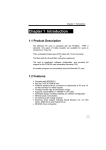
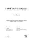
1.3-1 Front view
2
1
16
15
14
13
3
12
4
11
5
6
7
8
9
10
___________________________________________________________________________
12
General introduction
1
___________________________________________________________________________
Front view (cont)
1 Back-lit 8”1/2 VGA LCD screen with 256 colors.
2 Locks for the notebook cover.
3 Operating mode indicator lamps (see section 1.3-3).
4 PLC interface unit.
5 SUSPEND lamp, indicating the terminal operating mode.
6 SUSPEND pushbutton fore notebook stanby mode/restart.
7 DC socket for connecting the AC/DC adaptor when running from the AC supply.
8 Power-up switch.
9 Push RESET with a pencil point to reinitialize the FTX 417 notebook.
10 Battery lamp :
• green, when the notebook is powered-up,
• red, when the notebook battery is charging,
• orange, when the notebook battery is charged.
11 Keyboard (see section 1.3-3).
12 Pointing device built into the keyboard.
13 Micro-contact to switch LCD screen off when the notebook cover is closed.
14 Screen brightness adjustment.
15 Screen contrast adjustment.
16 Reverse video control (slide the button to the right or the left).
___________________________________________________________________________
13
A
A
___________________________________________________________________________
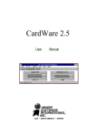
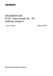
1.3-2 Rear view
1 2 3
4
5
6
7
8 9
10
11
12
13
6
___________________________________________________________________________
14
General introduction
1
___________________________________________________________________________
Rear view (cont.)
1 Indicator lamp, lights when the disk drive is operating.
2 Disk drive for IBM standard 3” 1/2 diskettes (1.44 Mb or 720 Kb).
3 Pushbutton for ejecting diskettes.
4 PCMCIA memory card slots.
5 Pushbuttons for ejecting PCMCIA memory cards.
6 Anti-theft rings.
7 Micro-DIN socket for connecting mouse or roller ball (IBM PS/2 standard).
8 Earthing screw.
9 15-pin female connector for connecting a color VGA or SVGA monitor.
10 Micro-DIN connector for external keyboard.
11 25-pin female connector for bidirectional parallel link (CENTRONICS standard).
12 9-pin male connector for RS 232C serial link (IBM PS/2 standard).
13 9-pin male connector for RS 232C serial link (IBM PS/2 standard).
Note
All the connectors, and the PCMCIA memory card and disk slots are protected by
covers.
___________________________________________________________________________
15
A
A
___________________________________________________________________________
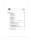
1.3-3 Keyboard
The FTX 417-40 notebook keyboards are complete (numeric keyboard, cursor keys,
etc), compatible with 101/102 key standard IBM keyboards. They are available in 6 basic
versions, other versions being obtained by attaching self-adhesive labels to the
keyboard (see Appendices section 12).
• QWERTY keyboard
4
5
6 7 8 9 10 11
12
1
A
NUM
F1
Esc
¬
`
Page
Up
Pause
Home
Break
Num
Lock
/
Delete
End
Page
Down
Print
screen
Sys Rq
Scroll
Lock
∗
F7
F8
F9
F10
F11
F12
&
*
8
(
Insert
SUSPEND
F2
!
HDD
F3
1
2
Q
F4
£
"
FDD
F5
$
3
W
CARD
%
4
E
F6
^
5
R
6
T
7
Y
U
0
O
8
9
4
5
6
1
2
3
Home
A
S
Z
\
Ctrl
Alt
D
X
F
C
G
V
H
B
J
N
K
M
L
;
′
>
?
.
/
Alt Gr
•
Del
Ins
]
@
,
2
}
:
<
+
0
=
{
[
Caps
Lock
Pg Dn
+
-
P
_
Pg Up
End
_
)
9
I
7
~
#
3
Ctrl
___________________________________________________________________________
16
General introduction
1
___________________________________________________________________________
Keyboard (cont.)
1 Pointing device.
2 Function keys and numeric keys.
3 Alphabetic keys and cursor keys.
4 SUSPEND pushbutton for notebook standby mode / restart.
5 SUSPEND indicator lamp.
6 "NUM" indicator lamp (green), indicating number lock on.
7 "A" indicator lamp (green), indicating caps lock on.
8 "ø" indicator lamp (green), indicating scrolling function locked.
9 HDD indicator lamp (green), lit when hard disk drive operating.
10 FDD indicator lamp (green), lit when floppy disk drive operating.
11 CARD indicator lamp (green), lit when the notebook accesses a PCMCIA memory
card.
12 Slot for quick reference guide.
A trap, opened with a coin, is located under the notebook. This allows access to the
battery.
___________________________________________________________________________
17
A
A
___________________________________________________________________________
1.4 FTX 417-40 special features
__________________________________________________________________________________________
1.4-1 Resident Multilingual SETUP
The FTX 417-40 notebook include a multilingual SETUP program (English, French,
German, Italian and Spanish).
This program is used to adjust and display the operating parameters of the notebook
(operating mode, hardware configuration, power supply management, I /O port assignment, etc) in the chosen language by simply using tables.
_______________________________________________________________________________________
1.4-2 Resident I/O system (BIOS)
The notebook has a Flash type EEPROM memory which enables easy integration of
new functions by Official Maintenance Centers.
_______________________________________________________________________________________
1.4-3 Energy saving features
The FTX 417-40 notebook has 3 energy saving features, intended principally to extend
the period of time the notebook may operate from the internal batteries.
• LCD screen saver : This feature switches off the screen if the notebook is not used
for a period of time set by the user (1). Operation is restarted automatically by pressing
a key.
• Hard disk saver : This feature stops operation of the hard disk if the notebook is not
used for a period of time set by the user (1). Operation is restarted automatically by
pressing a key.
• Management of processor speed : This feature controls the processor speed in
relation to the actual use of the notebook (1).
(1) All these are selected in SETUP (see section 5.2-4).
_______________________________________________________________________________________
1.4-4 Operating safety feature
Password
Each terminal is equipped with access control, limiting access to the terminal to
authorized personnel by means of a password. The password is defined in SETUP (see
section 5.2-4).
___________________________________________________________________________
18
General introduction
1
___________________________________________________________________________
1.4-5 PLC interface unit
The interface unit is fitted to the notebook without any modification to the appearance
of the notebook or to its dimensions.
This unit connects the notebook to PLCs and reads Telemecanique software protection
keys.
_______________________________________________________________________________________
1.4-6 Pointing device
The terminal is fitted with a pointing device, built into the keyboard as standard. This
gives quick access to the various command menus.
1
2
3
1 - Left hand button
2 - Moves the pointer through 360°
3 - Right hand buttons
___________________________________________________________________________
19
A
A
___________________________________________________________________________
1.5 Operating systems and utility software
________________________________________________________________________________________
1.5-1 Operating systems
The FTX 417-40 notebook is supplied withDOS and/or OS/2 and/or WINDOWS operating
systems pre-installed. The FTX 417-40 terminal functions are provided by the software
supplied by Telemecanique.
The operating systems are supplied on 3" 1/2 diskettes, each with their own documentation.
__________________________________________________________________________________________
1.5-2 Telemecanique utility software
Telemecanique utility software is divided into 2 groups :
• A SETUP program installed in the BIOS Flash EEPROM memory.
• DOS/WINDOWS and OS/2 utilities supplied on 3"1/2 diskettes.
The functions and installation of these programs are described in section 5.
__________________________________________________________________________________________
___________________________________________________________________________
20
________________________________________________________
Installing the basic hardware
2
InstaIling the basic hardware
Section 2
___________________________________________________________________________
___________________________________________________________________________
Sub-section
Page
___________________________________________________________________________________________
2.1
Checking the hardware
22
___________________________________________________________________________________________
___________________________________________________________________________________________
2.2
Preparation for use
23
___________________________________________________________________________________________
2.2-1 Setting up the battery
23
_______________________________________________________________________________
2.2-2
Preparing the notebook
23
_______________________________________________________________________________
2.2-3 Power connection
24
_______________________________________________________________________________
2.2-4
Using with internal battery
24
_______________________________________________________________________________
2.2-5 Switching on the first time
24
_______________________________________________________________________________
___________________________________________________________________________________________
2.3
Operating modes
25
___________________________________________________________________________________________
2.3-1 Managing usage time
26
_______________________________________________________________________________
_______________________________________________________________________________
2.4
Energy management modes
27
___________________________________________________________________________________________
_______________________________________________________________________________
2.5
Switching on
28
___________________________________________________________________________________________
2.5-1 Introduction
28
_______________________________________________________________________________
2.5-2 Self-tests
29
_______________________________________________________________________________
2.5-3 Error messages
30
_______________________________________________________________________________
_______________________________________________________________________________
2.6
Initializing the notebook
33
___________________________________________________________________________________________
This section ends at page
34
___________________________________________________________________________
21
B
___________________________________________________________________________
2.1
Checking the hardware
_______________________________________________________________________________________________
B
Terminal
Accessories
Documentation
and utilities
T FTX CA52 power cable
T FTX DM 417 40E
FTX 417-40 user's manual
T
T
X
T FTX ADC40
AC/DC adaptor
DOS utility software
3"1/2 diskettes
OS/2 utility software
3"1/2 diskettes
Options
According to
software configuration
Pointing device
Operating system
• DOS
• OS/2
• WINDOWS
T FTX MM2 M
___________________________________________________________________________
22
Installing the basic hardware
2
___________________________________________________________________________
2.2 Preparation for use
_______________________________________________________________________________________
When the FTX 417-40 notebook is used for the first time, the following operations must
be performed in the order in which sub-sections appear.
_______________________________________________________________________________________
2.2-1 Setting up the battery
The notebook is supplied with the battery disconnected. It must be in service before any
other operation can be performed.
To do this, open the trap underneath the notebook using a coin.
• Unscrew the 2 catches and open the trap.
• Lift up the battery.
• Remove the plastic protective film.
• Close the trap and tighten the catches.
_______________________________________________________________________________________
2.2-2 Preparing the notebook
Two sliding locks prevent the notebook
from opening. To open the notebook, slide
the locks and raise the lid as shown.
Remove the plastic protective film from the
screen.
___________________________________________________________________________
23
B
___________________________________________________________________________
2.2-3 Power connection
B
The FTX 417-40 notebook connects to a
100 - 240 VAC, 50 - 60 Hz supply, using
only the certified power supply adaptor
T FTX ADC 40 and a standard power
cable plugged in as shown.
_______________________________________________________________________________________
2.2-4 Using the internal battery
The internal battery must be charged before it can be used for the first time to power the
notebook.
The battery is charged by connecting the notebook to the AC/DC adaptor (see above)
and connecting this to the AC supply.
_______________________________________________________________________________________
2.2-5 Switching on the first time
Press the power-up switch, then during the self-tests press the F2 key to access the
main SETUP screen, and perform the following operations from that screen :
1- Using the up and down arrow keys, select "Language selection" and confirm with
<Enter>.
2- Using the up and down arrow keys, select "Operating parameters" and confirm with
<Enter> :
- set the date using the <+> and <-> keys,
- set the time using the <+> and <-> keys,
- enter a password if required.
All these operations are described in section 5.2-4.
Press <Escape> to return to the main menu.
3- Press <Escape>, select "Validate the changes and REBOOT" in the menu using the
up and down arrow keys and confirm with <Enter>.
___________________________________________________________________________
24
Installing the basic hardware
2
___________________________________________________________________________
2.3
_
______________Operating
_________________________modes
__________________________________________________________________________________________________________________________________
The FTX 417-40 notebook can operate on the mains power supply using the
T FTX ADC 40 adaptor or on the battery. The power supply lamp (see 1.3-1) and the
lamp above the SUSPEND button, depending on their state (steady, blinking) and their
color, inform the user about :
- the notebook operating mode,
- the charging status of the battery,
- the frequency of the processor
The table below summarizes the different states :
Battery
status
ON/OFF
switch
AC/DC
adaptor
SUSPEND
lamp
Power
supply lamp
Operating
mode
CHARGE
OFF
Present
Red steady Off
Orange steady Off
ON
Present
Green steady Green steady(1) Slow charge
Orange steady (2)
Press SUSPEND
ON
Present
Red steady
Orange
Fast charge
intermittent flash(3)
Orange
steady
Orange
intermittent flash
(3)
Fast charge
Slow charge
Slow charge
DISCHARGE
ON
OFF
Missing
Present
(1) Processor frequency = 33 MHz,
(2) Processor frequency < 33 MHz,
(3) a flash every 2 seconds.
Start of
Green steady Green
blinking slowly(1) discharge
5 short beeps
Green
blinking
slowly
Green
blinking quickly
Green
blinking
slowly
Orange
regular flash(3)
Terminal on low
consumption
Red
blinking
quickly
Off
Battery discharged
approx. 15 min left
___________________________________________________________________________
25
B
___________________________________________________________________________
B
In addition to the indicator lamps, audible beeps warn the user :
• 3 short beeps : indicate that the notebook is changing to battery operation.
• 1 long beep : indicates that the notebook is returning to the AC power supply.
• 5 short beeps indicate that there is approximately 15 minutes of independent
operation left.
Note :
Completely discharge and then recharge the battery at least once every two months to maintain
its performance.
_______________________________________________________________________________________
2.3-1 Managing usage time
The FTX 417-40 notebook has a number of features which increase the time during
which the notebook can operate independently :
• Standby modes. These enable the operation of an element of the notebook to be
temporarily shut down when not being used, after a period of time set by the user in
SETUP, see section 5.2-4.
• Using a PCMCIA memory card rather than diskettes.
___________________________________________________________________________
26
Installing the basic hardware
2
___________________________________________________________________________
2.4 Energy management modes
_______________________________________________________________________________________
The notebook has a "SUSPEND" button, at the top left hand side of the keyboard. This
button places the notebook in standby mode. Pressing the button again restarts the task
at the point where it was interrupted.
The lamp, associated with the "SUSPEND" button, changes color according to the
SETUP parameters. By its color, it shows the execution speed of the microprocessor as
well as the energy management mode :
Energy
management mode
AC power
SUSPEND lamp
Battery
SUSPEND lamp
Maximum
Slow
Waiting
Standby
Green
Orange
Orange
Orange intermittent flash
Green blinking
Orange blinking
Orange blinking
Orange intermittent flash
___________________________________________________________________________
27
B
___________________________________________________________________________
2.5 Switching on
_______________________________________________________________________________________
2.5-1 Introduction
B
The notebook is switched on by pressing the switch on the left hand side of the terminal,
regardless which power supply source has been chosen.
On power-up, the FTX 417-40 notebook executes a series of self-tests. The following
screen appears while the self-tests are running.
CL-GD62x5 VGA BIOS Version 1.22B
Copyright 1991-1994 Cirrus Logic, Inc. All Rights Reserved
Copyright 1991-1990 Quadtel Corp. All Rights Reserved
62x5 05/17/94
PhoenixBIOS(TM) A486 Version 1.03
Copyright (C) 1985-1992 Phoenix Technologies Ltd
All Rights Reserved
PhoenixBIOS for PicoPower PT86C368 (Pine)
Copyright (C) 1994 Telemecanique
486 DX processor detected operating at 33 Mhz
Press F2 to run the setup utility
After confirming SETUP or at the end of the self-tests, the notebook displays :
• The initial screen of the operating system.
• An error message if no operating system has been installed.
Switch on
FTX 417 40 notebook
Execution of
self-tests
F2
Terminal configuration
using SETUP software
Operating system
initial screen
___________________________________________________________________________
28
Installing the basic hardware
2
___________________________________________________________________________
2.5-2 Self-tests
On power-up, after initializing (by pressing the button with a pencil point, item 8, page 12)
or after a restart (by pressing <Control>, <Alt> and <Del>), the FTX 417 notebook
performs the various self-tests listed below in succession :
• ROM memory
• battery-backed CMOS RAM
• keyboard
• LCD screen (or external video screen)
• extended RAM
• serial ports
• parallel port
• pointing device
• disk drive
• hard disk
• processor speed
• bootable unit.
___________________________________________________________________________
29
B
___________________________________________________________________________
2.5-3 Error messages
If an error is detected during the self-tests, the following messages may appear :
B
Message
Probable cause
Solution
Diskette read failure - press
F1 to retry boot, F2 for
SETUP utility
The diskette is either not
formatted or is defective
Replace the diskette with a
bootable diskette and retry
Gate A20 failure
The keyboard controller is
not accepting commands,
specifically the enable and
disable A20 commands
Turn the power off, then
back on again. If the
problem persists, contact
your technical support
centre
Fixed disk configuration
error
The configuration is not
supported by the hardware
installed
Correct the fixed disk
configuration
Fixed disk controller failure
The controller card has
failed
Replace the fixed disk
Fixed disk failure
The fixed disk may be
defective
Try rebooting. If that does
not work, replace the fixed
disk
Hard disk failure - press F1
to retry boot, F2 for SETUP
utility
The fixed disk may be
configured incorrectly or is
defective
Check the drive type
selected in SETUP. Try
rebooting. If the problem
persists, replace the fixed
disk
Pointer device failure
The pointing device has
failed
Try rebooting. If the
problem persists, contact
your technical support
centre
No boot device available press F1 to retry boot, F2
for SETUP utility
Either diskette drive A:, the
PCMCIA card assigned as
A: or the fixed disk is
defective
Try rebooting. If the
problem persists, replace
the diskette, the PCMCIA
card or the hard disk
___________________________________________________________________________
30
Installing the basic hardware
2
___________________________________________________________________________
No boot sector on hard disk
- press F1 to retry boot, F2
for SETUP utility
The C: drive is not formatted or is not bootable
Format the C: drive and
make it bootable
B
Not a boot diskette - press
F1 to retry boot, F2 for
SETUP utility
The diskette or the
PCMCIA card in drive A: is
not formatted as a bootable
diskette
Replace the diskette or the
card with a bootable
diskette and try rebooting
No timer tick interrupt
The timer chip has failed
Turn the power off, then
back on again. If the
problem persists, contact
your technical support
centre
Shutdown failure
RESET command has
failed
Turn the power off, then
back on again. If the
problem persists, contact
your technical support
centre
Time of day not set - run
SETUP program
Clock not set
Run SETUP utility
Timer 2 failure
The timer chip has failed
Turn the power off, then
back on again. If the
problem persists, contact
your technical support
centre
Invalid configuration information - please run SETUP
Configuration error
Run SETUP utility and
check
configuration
settings
Keyboard data line failure
The keyboard controller
firmware has failed
Turn the power off, then
back on again. If the
problem persists, contact
your technical support
centre
___________________________________________________________________________
31
___________________________________________________________________________
Keyboard stuck key failure
A key is jammed
Locate the jammed key and
fix it. Turn the power off,
then back on again. If the
problem persists, contact
your technical support
centre
Memory failure at hex-value, read hex-value,
expecting hex-value
Memory chip has failed
Turn the power off, then
back on again. If the
problem persists, contact
your technical support
centre
Real time clock failure
The RTC or battery has
failed
Run the SETUP utility and
turn the power off and on. If
the problem persists,
replace the battery. If the
problem remains, contact
your technical support
centre
Memory parity interrupt at
address. Type (S)hut off
NMI, (R)eboot, other keys
to continue
Memory chip has failed
Contact your technical
support centre
Unexpected HW interrupt
interrupt at address. Type
(R)eboot, other keys to
continue
Hardware problem
Contact your technical
support centre
Unexpected SW interrupt
interrupt at address. Type
(R)eboot, other keys to
continue
Errors in the software
program
Turn the power off, then
back on again. If the
problem persists, check the
program
Unexpected type 02 interrupt at xxxxxh. Type (S)hut
off NMI, (R)eboot, other
keys to continue
A parity error occurred, but
the source cannot be
determined
Turn the power off, then
back on again
B
___________________________________________________________________________
32
Installing the basic hardware
2
___________________________________________________________________________
2.6
Initializing the notebook
_______________________________________________________________________________________
The FTX 417-40 notebook can be initialized in 3 ways (has 3 bootable drives) :
- Diskettes
- Hard disk
- PCMCIA cards.
When a diskette is in the drive, it has priority, except when drive A has been assigned
to a PCMCIA slot in SETUP.
The terminal cannot start up in the following situations :
• There is either a non formatted or non-system disk in drive A:
• Drive A: is assigned to a PCMCIA slot which contains either a non formatted or
non-system memory card.
• The hard disk is not formatted or the operating system is not installed (no diskette in
the drive).
___________________________________________________________________________
33
B
___________________________________________________________________________
B
___________________________________________________________________________
34
________________________________________________________
Installing external extensions
3
Installing external extensions
Section 3
___________________________________________________________________________
___________________________________________________________________________
Sub-section
Page
_______________________________________________________________________________________
3.1
Mouse
36
_______________________________________________________________________________________
3.1-1 General
36
_______________________________________________________________________________
3.1-2 MOUSE pin connections
36
_______________________________________________________________________________
_______________________________________________________________________________________
3.2
Monitors
37
_______________________________________________________________________________________
3.2-1 General
37
_______________________________________________________________________________
3.2-2 VIDEO (VGA) pin connections
37
_______________________________________________________________________________
_______________________________________________________________________________________
3.3
Printers
38
_______________________________________________________________________________________
3.3-1 General
38
_______________________________________________________________________________
3.3-2 RS 232C "RS232C(COM1) serial port connections"
38
_______________________________________________________________________________
←
3.3-3 CENTRONICS “// → (LPT1)” parallel port pin connections
39
_______________________________________________________________________________
_______________________________________________________________________________________
3.4
Keyboards
40
_______________________________________________________________________________________
3.4-1 General
40
_______________________________________________________________________________
3.4-2 KEYBOARD pin connections
40
_______________________________________________________________________________
This section ends at page
40
___________________________________________________________________________
35
C
___________________________________________________________________________
3.1 Mouse
_______________________________________________________________________________________
3.1-1 General
Telemecanique supplies a mouse (ref. T FTX MM 2 M) in addition to the pointing device
on the keyboard.
This mouse is connected via the dedicated
mouse port : micro DIN serial link
IBM PS/2 standard connector.
C
Caution
Do not connect or disconnect the mouse
when the notebook is switched on.
The mouse driver must be installed for
the mouse to be operational (see
documentation supplied with the mouse).
Important
Once the external mouse has been installed, the pointing device on the keyboard is
disabled.
_______________________________________________________________________________________
3.1-2 Mouse pin connections
Micro-Din 6-pin female connector (front view)
6
5
4
3
2 1
_____________________________________________________________________
Pin N°
Signal
I/O
Description
_______________________________________________________________________________________
1
MDATA
I/O
Data
_______________________________________________________________________________________
2
NC
Not connected
_______________________________________________________________________________________
3
0V
Ground (Earth)
_______________________________________________________________________________________
4
5V
5 VDC
_______________________________________________________________________________________
5
MCLK
O
Clock
_______________________________________________________________________________________
6___________________________________________NC
_
_____________________________________-_____________________________________Not
_______connected
_________________________________________________
___________________________________________________________________________
36
Installing external extensions
3
___________________________________________________________________________
3.2 Monitors
_______________________________________________________________________________________
3.2-1 General
The FTX 417-40 notebook has an IBM
PS/2 standard 15-pin video connector. It
will accept any color or monochrome
monitor. It supports VGA and SVGA graphic
resolutions and enables up to 256 colors to
be displayed.
The notebook must be powered down
when connecting an external monitor. This
monitor then has priority over the LCD
screen which is inhibited.
C
_______________________________________________________________________________________
3.2-2 VIDEO pin connections
Front view of female connector
5 4 3 2
1
10 9 8 7 6
15 14 13 12
11
____________________________________________________________________
Pin
N°
Signal
I/O
Description
_______________________________________________________________________________________
1
RED
O
Red
_______________________________________________________________________________________
2
GREEN
O
Green
_______________________________________________________________________________________
3
BLUE
O
Blue
_______________________________________________________________________________________
4
Reserved
Reserved
_______________________________________________________________________________________
5
Self-test
O
Self-test output
_______________________________________________________________________________________
6/7/8
0V
Ground red/green/blue
_______________________________________________________________________________________
9
PLUG
Locating
_______________________________________________________________________________________
10
0V
Ground
_______________________________________________________________________________________
11/12
Reserved
Reserved
_______________________________________________________________________________________
13
HSYNC
O
Horizontal synchro
_______________________________________________________________________________________
14
VSYNC
O
Vertical synchro
_______________________________________________________________________________________
15
NC
-
Not connected
___________________________________________________________________________
37
___________________________________________________________________________
3.3 Printers
_______________________________________________________________________________________
3.3-1 General
C
The FTX 417-40 notebook will accept
various types of serial printer via the
RS232C interface, or parallel printers via
the Centronics interface. The corresponding
printer driver must be installed. Lists of
printer drivers are provided by the operating
systems.
The drivers can be selected either during
installation, or later (see operating system
installation manual).
_______________________________________________________________________________________
3.3-2 RS 232 “RS232C(COM1)” and "RS232C(COM2)” serial port pin
connections
Male connector (front view)
1 2 3 4
5
6 7 8 9
____________________________________________________________________
Pin N°
Signal
I/O
Description
_______________________________________________________________________________________
1
DCD
O
Data Carrier Detect
_______________________________________________________________________________________
2
RXD
O
Data received
_______________________________________________________________________________________
3
TXD
O
Data transmitted
_______________________________________________________________________________________
4
DTR
O
Data Terminal Ready
_______________________________________________________________________________________
5
0V
Signal ground
_______________________________________________________________________________________
6
DSR
I
Data Set Ready
_______________________________________________________________________________________
7
RTS
O
Request to Send
_______________________________________________________________________________________
8
CTS
I
Clear to Send
_______________________________________________________________________________________
9
RI
I
Audible signal
_______________________________________________________________________________________
___________________________________________________________________________
38
Installing external extensions
3
___________________________________________________________________________
3.3-3 CENTRONICS “// ←
→ (LPT1)” parallel port pin connections
Female connector (front view)
13 12 11 10 9 8 7 6 5 4 3 2 1
25 24 23 22 21 20 19 18 17 16 15 14
____________________________________________________________________
Pin
N°
Signal
I/O
Description
_______________________________________________________________________________________
1
-STROBE
O
Strobe
_______________________________________________________________________________________
2
D0
I/O
Data bit 0
_______________________________________________________________________________________
3
D1
I/O
Data bit 1
_______________________________________________________________________________________
4
D2
I/O
Data bit 2
_______________________________________________________________________________________
5
D3
I/O
Data bit 3
_______________________________________________________________________________________
6
D4
I/O
Data bit 4
_______________________________________________________________________________________
7
D5
I/O
Data bit 5
_______________________________________________________________________________________
8
D6
I/O
Data bit 6
_______________________________________________________________________________________
9
D7
I/O
Data bit 7
_______________________________________________________________________________________
10
-ACK
I
Acknowledge
_______________________________________________________________________________________
11
BUSY
I
Busy
_______________________________________________________________________________________
12
PE
I
End of paper
_______________________________________________________________________________________
13
SLCT
I
Select
_______________________________________________________________________________________
14
-AUTOFEED
O
Automatic linefeed
_______________________________________________________________________________________
15
-ERROR
I
Error
_______________________________________________________________________________________
16
-INIT
O
Printer initialization
_______________________________________________________________________________________
17
-SLCTIN
O
Input selection
_______________________________________________________________________________________
18/19/20
0V
Signal ground
_______________________________________________________________________________________
21/22/23
0V
Signal ground
_______________________________________________________________________________________
24/25
0V
Signal ground
_______________________________________________________________________________________
___________________________________________________________________________
39
C
___________________________________________________________________________
3.4 Keyboards
_______________________________________________________________________________________
3.4-1 General
The FTX 417-40 notebook has a 6-pin
Micro-DIN female connector. It will accept
any IBM/PS2 compatible keyboard.
An external IBM AT type keyboard can
also be connected via a DIN/MICRODIN
adaptor, reference : T FTX KBA 5.
C
_______________________________________________________________________________________
3.4-2 KEYBOARD pin connections
Micro-Din 6-pin female connector (front
view)
6
5
4
3
2 1
_____________________________________________________________________
Pin N°
Signal
I/O
Description
_______________________________________________________________________________________
1
KDATA
I/O
Data
_______________________________________________________________________________________
2
NC
Not connected
_______________________________________________________________________________________
3
0V
Ground
_______________________________________________________________________________________
4
5V
5 VDC
_______________________________________________________________________________________
5
KCLOCK
O
Clock
_______________________________________________________________________________________
6___________________________________________NC
_
_____________________________________-_____________________________________Not
_______connected
_________________________________________________
___________________________________________________________________________
40
___________________________________________________
4
Section 4
Connecting to Telemecanique products
Connecting to Telemecanique
products
___________________________________________________________________________
___________________________________________________________________________
Sub-section
Page
__________________________________________________________________________________________________
4.1
PLC interface unit
42
__________________________________________________________________________________________________
__________________________________________________________________________________________________
4.2
Connecting to TSX range of PLCs
43
_______________________________________________________________________________________________
4.2-1 Connecting to TSX 07 and TSX 17 PLCs
43
_______________________________________________________________________________
4.2-2 Connecting to TSX/PMX 47/67/87/107 PLCs
44
_______________________________________________________________________________
4.2-3 Connecting to UNI-TELWAY bus
45
_______________________________________________________________________________
__________________________________________________________________________________________________
4.3
Connecting via a modem
46
__________________________________________________________________________________________
This section ends at page
46
___________________________________________________________________________
41
C
___________________________________________________________________________
4.1
interface
_
______________PLC
____________
______________________unit
___________________________________________________________________________________________________________________________
C
The FTX 417-40 notebook has a
multifunction port which enables it to be
connected directly to Telemecanique
products. This port is located in the PLC
interface unit. This port offers 2
standards :
• CL20 (20 mA current loop) for connecting
to TSX 47/67/87 version V3 or later or
TSX/PMX 47/67/87/107 model 40 PLCs.
• RS 485 for connecting to TSX 07 and
TSX 17 PLCs.
Using Telemecanique software automatically selects the port according to the PLC
connected. However, to speed up the logical connection, this choice can be configured
in the SETUP software (see section 5.2-4).
Connector
PLC interface unit
PLC interface unit
26-pin connector
RS 485 or CL 20
Rear view
Connection point for
software protection key
(1)
Front view
(2)
(1) PLCs are connected to the notebook via the rear of the connector.
(2) The Telemecanique software protection key is connected at the front of the
connector.
The PLC interface unit contains an integral key for checking the rights required for using
the Telemecanique software installed on the hard disk.
(For the use of Key-manager refer to Telemecanique software documentation).
___________________________________________________________________________
42
Connecting to Telemecanique products
4
___________________________________________________________________________
4.2
to
of
_
______________Connecting
______________________________
______TSX
___________range
________________
______PLCs
________________________________________________________________________________________
4.2-1 Connecting to TSX 07 and TSX 17 PLCs
AC supply
T FTX CBF 020
cable
TSX 07
C
T FTX CB 1030 cable
26-pin serial link
connector (COM2)
15-pin
connector
FTX 417-40
TSX 17-20
AC supply
Connecting to PLCs requires a T FTX CBF 020 cable (length 2.5m) for the TSX 07 and
a T FTX CB 1 030 cable (length 3m) for the TSX 17.
These cables have :
• for the TSX 07 :
- on the FTX 417 side; a 26-pin SUB-D male connector,
- on the TSX 07 side; an 8-pin mini-DIN female connector.
• for the TSX 17 :
- on the FTX 417 side; a 26-pin SUB-D male connector,
- on the TSX 17 side; a 15-pin SUB-D male connector.
Note
The cables for connecting to PLCs must be ordered separately.
___________________________________________________________________________
43
___________________________________________________________________________
4.2-2 Connecting to TSX/PMX 47/67/87/107 PLCs
TSX/PMX 47/67/87/107
FTX 417-40
C
T FTX CB 75 cable
26-pin serial link
connector
(COM2)
AC supply
Connecting to TSX/PMX PLCs requires a T FTX CB 7 5 cable (to be ordered separately).
This 2m cable has :
• on the FTX 417 side; a 26-pin SUB-D male connector,
• on the TSX/PMX side; a 9-pin SUB-D male connector.
___________________________________________________________________________
44
Connecting to Telemecanique products
4
___________________________________________________________________________
4.2-3 Connecting to UNI-TELWAY bus
Connecting the notebook to UNI-TELWAY simplifies local maintenance of an application
which includes a UNI-TELWAY bus.
Connecting to the UNI-TELWAY bus is only possible if the UNI-TELWAY driver is
installed. This driver is supplied with X-TEL and MINI X-TEL software (for further
information, see the X-TEL or MINI X-TEL reference manual).
Connection is made via a TSX SCA 62 subscriber socket and the T FTX CB 1 030 cable
(to be ordered separately).
C
This 3m cable has :
• on the FTX 417 side; a 26-pin D male connector,
• on the TSX SCA62 side; a 15-pin D male connector.
26-pin serial link
connector
(COM2)
TSX SCA 62
TSX SCA 62
TSX SCA 62
T FTX CB 1030
FTX 417-40
The notebook can also be connected to the integral UNI-TELWAY port on the processor
using a T FTX CB2 030 cable.
___________________________________________________________________________
45
___________________________________________________________________________
4.3
via
_
______________Connecting
______________________________
________a
____modem
___________________________________________________________________________________________________________________
The notebook can be connected via a modem to a PLC for the purpose of remote
maintenance.
• TSX range
C
The modem can only be connected if the UNI-TELWAY driver is installed. This driver is
supplied with :
- X-TEL and MINI X-TEL software
- SYSDIAG under PL7-DOS user interface.
For further information, refer to the relevant manuals.
FTX 417-40
Telephone link
Modem
PCMCIA card
Modem
The modem is connected to the notebook using a Fax Modem type 2 PCMCIA card.
___________________________________________________________________________
46
___________________________________________________
Telemecanique utility software
5
Telemecanique utility software
Section 5
___________________________________________________________________________
___________________________________________________________________________
Sub-section
Page
_______________________________________________________________________________________
5.1
Introduction to the utilities
48
_______________________________________________________________________________________
_______________________________________________________________________________________
5.2
Integrated utility (SETUP)
48
_______________________________________________________________________________________
5.2-1 Accessing the SETUP software
48
_______________________________________________________________________________
5.2-2 Introduction to the main menu
49
_______________________________________________________________________________
5.2-3 Operational flow chart
50
_______________________________________________________________________________
5.2-4 Operating parameters
52
_______________________________________________________________________________
5.2-5 Language selection
59
_______________________________________________________________________________
5.2-6 Initializing all parameters
60
_______________________________________________________________________________
5.2-7 Saving modifications
60
_______________________________________________________________________________
_______________________________________________________________________________________
5.3
61
_
______________Utilities
__________________on
_______diskette
__________________________________________________________________________________________________________________________________
____
_______________________________________________________________________________________
5.4
DOS
LF
TDS
62
_
______________Utility
______________under
_______________
___________(T
_____FTX
___________
_______
__________40)
__________________________________________________________________________________
____
_______________________________________________________________________________________
5.5
OS/2
64
_______________Utility
______________under
_______________
___________(T
______FTX
__________LF
_______TS2
__________52)
__________________________________________________________________________________
____
_______________________________________________________________________________________
5.6
64
_______________Other
______________utilities
_____________________________________________________________________________________________________________________________________________
____
This section ends at page
64
___________________________________________________________________________
47
D
___________________________________________________________________________
5.1 Introduction to the utilities
_______________________________________________________________________________________
The FTX 417 notebook has 2 types of utilities :
• A SETUP utility which is integrated into the BIOS Flash EEPROM memory.
• A set of DOS and OS/2 utilities supplied on 3"1/2 diskettes.
5.2
Integrated utility (SETUP)
_______________________________________________________________________________________
5.2-1 Accessing the SETUP software
The SETUP program is accessed during the self-tests when the terminal is switched on
or restarted (press the <Control>, <Alt> and <Del> keys), by holding down the <F2> key.
D
Note
If a password has previously been defined, it must be entered in order to access the SETUP
program (only when switching on).
This method launches SETUP in the language previously defined. To obtain SETUP
software in another language, launch SETUP and choose language selection in the
menu.
___________________________________________________________________________
48
Telemecanique utility software
5
___________________________________________________________________________
5.2-2 Introduction to the main menu
TELEMECANIQUE
MAIN
417
CONFIGURATION
Version
1.0
MENU
Operating
Parameters
Communication
Power
FTX
Ports
Management
Language Selection
Initialize Operating Parameters
(Load default values, except password)
Select : Enter
Exit : Esc
Help : F1
Abort : End
This screen provides access to the FTX 417 notebook configuration parameters :
- Operating parameters (date, time, password, self-tests, etc).
- Assignment of the communication ports.
- Power management, processor speed, standby mode configuration.
- Language selection. This selection determines in which language the SETUP
program is displayed.
- Initialization of all the parameters to their default values.
Purpose of the main keys
The vertical move keys are used to select parameters on the screen.
The <Esc> key quits either the current function, or the SETUP program.
A help file corresponding to the screen displayed and the subject selected, can be
accessed at any time by pressing F1.
___________________________________________________________________________
49
D
___________________________________________________________________________
5.2-3 Operational flow chart
Main
Menu
Parameter
selection
Esc
Enter
Operating
Parameters or
Communication
Port or
Power Management
D
Language
Initialization
Esc
selection
of parameters
Esc
Enter
Enter
Enter
List of
choices
Enter
Choice
selected
___________________________________________________________________________
50
Telemecanique utility software
5
___________________________________________________________________________
Operating parameters
The operating parameters are divided into three screens. Move from one screen to
another by pressing the PgUp and PgDown keys.
The operating parameters contain all parameters, including the communication ports,
selection of power management and of the language which can also be accessed
directly from the main menu.
Some values, given by the system, cannot be accessed by the user for modification.
(these values are displayed in white).
Modifying digital values
Digital values such as date and time can be modified by the <+> and <-> keys.
Important
The modified parameters are only taken into account when quitting the SETUP
program after confirmation. Data concerning the date, time and password take
effect immediately.
When selecting a parameter, an entry window gives the various choices available or
indicates any syntax which must be followed.
Confirming and quitting SETUP
Main
Menu
Esc
Enter
Return to MAIN MENU
Quit without modification
Confirmation and reinit ializ ation (REBOOT)
___________________________________________________________________________
51
D
___________________________________________________________________________
5.2-4 Operating parameters
Selecting “Operating parameters" in the main menu accesses in succession the 3
screens which contain all the notebook parameters. The PgUp and PgDown key are
used to move from one screen to another.
Description of the first screen, which contains :
•
•
•
•
•
•
•
•
•
•
•
Date and time
Definition of password
Execution of self-tests on power up
Status of the battery-backed CMOS RAM memory
Selecting a PS/2 type mouse
Total RAM size
Disk drive assignment
Hard disk capacity
BIOS version
Update time
Serial number
D
CONFIGURATION
TELEMECANIQUE
OPERATING
FTX
417
Version
1.0
PARAMETERS
Date (DD/MM/YYYY). . . . .
Time (HH:MM:SS). . . . .
Password . . . . . . .
Self-tests . . . . . . .
CMOS RAM status. . . .
PS/2 Mouse . . . . . . . .
Total main DRAM size . . .
Floppy drive assignment .
20/12/94
19:41:04
Absent
Complete
Checksum OK
Enabled
12Mb
A: FDD
B: Disabled
HDD C:. . . . . . .
125 Mb
BIOS Version . . . . . . .
V 1.0.
Update (DD/MM/YY) . .
01/12/94
Serial number . . . . . . 90000012
1/3
Next Page : PgDn
Select : Enter
Exit : Esc
Help : F1
Abort : End
___________________________________________________________________________
52
Telemecanique utility software
5
___________________________________________________________________________
Date
Enables the date to be updated in the format indicated, the <+> and <-> keys are used
to increment or decrement the digital values.
Time
Enables the time to be updated in the format indicated, the <+> and <-> keys are used
to increment or decrement the digital values.
Password
This function allows a password of 3 to 8 alphanumeric characters to be defined or
cancelled. When declared, the password is required each time the terminal is switched
on. After three unsuccessful attempts, the terminal must be switched on again.
• Creating a password : When the terminal has no password, enter the chosen
password twice in succession.
• Modifying a password : Enter the old password then enter the new one twice in
succession.
• Deleting a password : Enter the old password then press <Enter> twice in succession.
If the user has lost the password, he should contact the Telemecanique Regional Sales
Office giving :
•
•
•
•
His details : name and address of the company, telephone and fax numbers.
The serial number on the product.
The system reference : ... (displayed on the screen after 3 attempts).
The user access code "UAC" : .... (displayed on the screen after 3 attempts).
The Telemecanique Regional Sales Office will a provide a special code which will enable
the FTX 417 notebook to be reinitialized and a new password defined. This unique code
will have no effect if used a second time if the password is lost again.
Important
The password system relies on the position of the keys used and not on their
markings. It is therefore strongly recommended that the type of keyboard is not
changed after the password has been entered. For example, the password “WQA”
on a QWERTY keyboard corresponds to the password “ZAQ” on an AZERTY
keyboard).
___________________________________________________________________________
53
D
___________________________________________________________________________
Self-tests
This parameter is used to select how the self-tests are executed when the FTX 417
notebook is switched on :
• Complete :
Tests the entire RAM memory
• Quick :
Tests only basic memory (640 Kb) and the system memory (384 Kb). This choice
significantly reduces time taken for tests on a terminal with a large RAM memory.
CMOS RAM status
This function initializes the contents of the CMOS RAM, after confirmation, if the
checksum is incorrect. An incorrect checksum indicates that at least one of the
configuration elements is damaged or that the lithium back-up battery is not in service.
PS/2 Mouse
This activates or deactivates the pointing device on the keyboard.
Total DRAM size
D
Set parameter which determines the total RAM size.
Disk drive
Assigns the disk drives and PCMCIA card reader to drive <A:> or <B:>.
The next information indicates the size of the hard disk, the BIOS version and its update
as well as the notebook serial number.
___________________________________________________________________________
54
Telemecanique utility software
5
___________________________________________________________________________
Description of the second screen, containing :
• Assignment of the communication ports.
• Definition of TE key interface.
CONFIGURATION
TELEMECANIQUE
OPERATING
FTX
417
Version
1.0
PARAMETERS
COMMUNICATION PORTS :
- COM1 assignment . .
- COM2 assignment . .
- COM2 communication mode .
- LPT1 assignment . .
- LPT1 mode . . . .
- TE dongle key interface .
COM1 (default)
COM2 (default)
CL20
LPT1 (default)
Bidirectional
Enabled
D
2/3
Page change : PgDown / PgUp
Select : Enter
Exit : Esc
Help : F1
Abort : End
COM1 assignment
Configures serial port 1 to COM1 or COM3 or disables this port.
COM2 assignment
Configures serial port 2 to COM2 or COM4 or disables this port.
COM2 communication mode
Choice between current loop (CL20), multidrop power connection (RS485), power
connection (RS232C). If the connection unit is missing, the RS 232 C connection is
implicit.
LPT1 assignment
Configuration of parallel port (printer link and TE 90 key support) to LPT1 (default) or
LPT2 or port disabled.
LPT1 mode
Declared as the printer port or bidirectional : network connection, mass memory.
___________________________________________________________________________
55
___________________________________________________________________________
TE dongle key interface
Activates or deactivates the Telemecanique software protection key interface and PLC
connections (CL20/RS 485).
Important
The modified parameters are only taken into account after quitting SETUP.
Selecting a higher communication port index implies that the lower indices must be
used (for example, if COM3 is declared, COM1 and COM2 must be used).
The connection unit has a port assigned to COM2 (when it is not disabled), which is
dedicated to interfacing with Telemecanique TSX PLCs. This port can be programmed
in two communication formats :
• RS 485 for connecting to the UNI-TELWAY bus, to TSX 07 and TSX 17 micro-PLCs.
D
• Current loop (CL 20) for communicating with Telemecanique Series 7 PLC terminal
ports.
Note
The LPT1 port must be declared in order to use the X-TEL or MINI X-TEL software workshop.
___________________________________________________________________________
56
Telemecanique utility software
5
___________________________________________________________________________
Description of the third screen, containing :
CONFIGURATION TELEMECANIQUE FTX 417 Version 1.0
OPERATING
PARAMETERS
LCD shutdown after
Disabled
HDD shutdown after
Disabled
Power management style
Average
Power management conditions Enabled
Suspend style
Suspend/Resume
Avr
Eco
Perf
User1 User2
SPEED
Full
33 MHz 33 MHz 33 MHz 33 MHz 33MHz
Idle
8 MHz 8 MHz 1 MHz 1 MHz
OFF
Standby 8 MHz 2 MHz 1 MHz
1 MHz
OFF
TIMEOUT
Idle
8 sec 1 sec
OFF
OFF
OFF
Standby 6 min 1 min
OFF
1mm
OFF
Suspend 20 min 5 min
OFF
5mm
OFF
3/3 Prev Page : PgUp
Select : Enter
Exit : Esc
Help : F1
Abort : End
LCD shutdown after
Activates and deactivates the screen saver after a period of 1 to 15 minutes, which can
be configured in units of a minute. Pressing any key will reactivate the screen.
This screen saver reduces the notebook's electrical consumption when it is powered
from its own battery.
HDD shutdown after
Places or removes the hard disk to/from standby mode after a period of 1 to 12 minutes.
The notebook restarts automatically as soon as access is requested.
This operating mode reduces the battery consumption. When the disk is placed in
standby mode, the read/write heads are parked and locked, which enables the notebook
to be transported without being damaged.
___________________________________________________________________________
57
D
___________________________________________________________________________
Power management style
Power management of the notebook makes it possible to select the battery performance
level and minimize consumption. Each style can be modified by the notebook user
according to how the notebook is being used.
These 5 operating styles are :
- Average (Avr),
- Economical ( Eco),
- Performance (Perf),
- User 1 (User1),
- User 2 (User2).
Each of the management styles defines the processor speed according to the frequency
characteristics of the clock and time before change to standby mode.
Power management conditions
This menu activates or deactivates power management which has been previously
defined. The "Disabled" setting deactivates management mode as soon as the notebook
is connected to the AC supply via the adaptor.
D
Suspend style
The electrical consumption is minimal when the notebook is in Suspend/Resume mode.
The memory continues to be updated quickly. Data can be obtained as long as the
battery is sufficiently charged.
The "Save to disk" setting saves data to disk, thereby increasing the operation time,
however ensuring that the data is definitely saved. Disk space is assigned for this
function (see PHDISK utility program).
Full speed
The processor speed maintains the defined value (33, 16.5 , 8 or 4 MHz) as long as the
notebook is in ON mode. The higher the processor clock frequency, the higher the
battery performance and consumption.
Idle mode
The processor clock speed is set to idle mode. Frequency values can be set to : 8, 4,
2, 1 or 0.5 MHz or OFF.
Standby mode
This mode characterizes the processor clock frequency when the notebook is in
"standby". Frequencies vary from 8, 4, 2, 1 to 0.5 MHz.
Idle timeout
This is the time taken to change to idle mode at the frequency defined in the "idle FREQ"
setting or switching the processor off. It is possible to disable this operating mode or
select times from 1, 4, 8 or 16 seconds.
Standby timeout
Time taken to change the processor to standby mode. Values which can be configured :
1, 2, 4 , 6, 8, 12 or 16 minutes. This setting can be disabled.
___________________________________________________________________________
58
Telemecanique utility software
5
___________________________________________________________________________
Suspend time
Length of time the notebook is in standby mode. This can be configured with times
ranging from 5, 10, 15, 20, 30, 40 to 60 minutes. This setting can be disabled.
The notebook restarts as soon as the SUSPEND key is pressed.
Pressing the SUSPEND key will place the notebook in standby mode at any time.
Important
When the battery charge becomes critically low, the notebook is automatically placed
in standby mode; the data is saved to the RAM memory.
It is not possible to save to a disk.
5.2-5 Language selection
“Language selection” in the main menu allows the user to select the language in which
the configuration utility (SETUP) is to run. Languages available are English, French,
German, Italian and Spanish.
LANGUAGE SELECTION
English
Fran ais
Deutsch
Italiano
Espanol
:
:
:
:
:
Select the country
S lectionner la nationalit
Wahlen Sie die Nationalitat
Selezionare la nazionalit
Seleccionar el idioma
Changing the language takes effect immediately.
___________________________________________________________________________
59
D
___________________________________________________________________________
5.2-6 Initializing all parameters
Selecting “Initialize operating parameters” in the main menu enables all the parameters
to be reset to the default values (except the password, the date and the time).
• Initialization :
starts initialization of all parameters,
• Quit :
returns to the main menu without initializing.
The
default parameters are as follows :
_____________________________________________________________________________________________
Self-tests
Complete
_____________________________________________________________________________________________
PS/2 Mouse
Enabled
_____________________________________________________________________________________________
Floppy drive assignment
A: FDD
B: Disabled
_____________________________________________________________________________________________
Communication ports
• COM1 (RS232 C)
• COM2 (RS 232 C, RS 485, CL20)
• COM2 port status
• Parallel port
COM1
COM2
CL20
LPT1 Bidirectional
_____________________________________________________________________________________________
TE dongle key interface
Enabled
____________________________________________________________________________________________
D
LCD shutdown after
Disabled
___________________________________________________________________________________________
HDD
after
__________shutdown
____________________
_____________________________________________________________________________________Disabled
_________________________________________________
Power management style
Enabled
___________________________________________________________________________________________
Power management conditions
Average
___________________________________________________________________________________________
Suspend style
Suspend/Resume
___________________________________________________________________________________________
Language
selection
English
___________________________________________________________________________________________
5.2-7 Saving modifications
Once all the modifications have been entered they must be saved.
This is done from the main menu of the SETUP program by pressing the following key :
<Esc> : displays the following screen :
Are the modifications correct ?
Return to main menu
Quit without modification
Confirmation & reinitialization (REBOOT)
Select "Confirmation and reinitialization (REBOOT)" using the up and down arrows, and
confirm the choice by pressing <Enter>
Selecting "Return to main menu" allows you return to the main menu.
Selecting "Quit without modification" cancels all the modifications.
___________________________________________________________________________
60
Telemecanique utility software
5
___________________________________________________________________________
5.3 Utilities on diskette
_______________________________________________________________________________________
A set of DOS and OS/2 utilities are supplied with the FTX 417 40 notebook on 3"1/2
diskettes.
The table below gives a list and their function according to the operating systems
installed : DOS, WINDOWS and OS/2.
DOS
WINDOWS
OS/2
List of utilities
T FTX LF TDS 40
DOS software utility diskette
for FTX 417-40
X
T FTX LF DS PCM
PCMCIA software utility diskette
under DOS for FTX 417-40
X
X
D
T FTX LF TS2 52
OS/2 software utility diskette
for FTX 417-40
X
T FTX LF SVGA 40
SVGA software utility diskettes under
DOS and OS/2 for FTX 417-40
X
X
T FTX LF FFS
Flash file system software utility
diskette for FTX 417-40
X
X
X
Function not available
Note
The utilities are pre-installed.
___________________________________________________________________________
61
___________________________________________________________________________
5.4
Utility under DOS (T FTX LF TDS 40)
_______________________________________________________________________________________
The T FTX LF TDS 40 diskette contains the following utilities :
- MOUSE.COM :
controls the pointing device which is built into the notebook
- PHDISK.COM :
save to disk utility (see section 8)
- T607TOPC.EXE : file conversion utility
Installation procedure
At the DOS prompt, type :
A:\>Install then press <Enter>, and follow the instructions displayed.
T607TOPC
The following commands are used to convert files created on a T607 terminal for use
on the FTX 417-40 notebook.
D
Note
To import an application stored on a "HD" diskette, the write protect tab must be
covered with a label as shown in the diagram.
Tab
T607TOPC
Lists the set of commands described below.
T607TOPC DIR <source drive>
Displays the list of files contained in the T607 diskette.
• Insert the T607 diskette in the drive.
• Enter the command T607TOPC DIR <source drive>.
example : C:\TE_TOOLS>T607TOPC DIR a:
FURNACE
151324
FURNACE. CAB
196
FURNACE. TIT
100
FURNACE. NET
158
. . . .. . .
...
The screen displays the name of the files with their extensions and the size in number
of bytes.
The *.BIN files (containing the application programs created on TSX T607 terminals) are
read without their extensions by the FTX 417 workstation.
___________________________________________________________________________
62
Telemecanique utility software
5
___________________________________________________________________________
T607TOPC <source drive>:\*.* <destination>
Copies the entire contents of the T607 diskette to the selected DOS directory.
• Create a directory under DOS,
example : C:\>MKDIR APV3
• Insert the T607 diskette in the drive.
• Enter the command T607TOPC <source drive>:\*.* <destination>.
example : C:\TE_TOOLS>T607TOPC a:\*.* c:\APV3
All the T607 files on the diskette are then copied to the directory.
T607TOPC <source drive>:\<T607 name> <destination>
Copies the file selected on the T607 diskette to the selected DOS directory.
• Create a directory under DOS.
example : C:\MKDIR APV3
• Insert the T607 diskette in the drive.
• Enter the command T607TOPC <source drive>:\<T607 name> <destination>.
example : C:\TE_TOOLS>T607TOPC a:\FURNACE c:\APV3
Note
To use the original files after transfer (from the TSX T607 terminal), they must have
an extension. If there is no extension, the .BIN extension must be added using the
DOS command “RENAME” :
Example : RENAME <PATH> FILE FILE.BIN
___________________________________________________________________________
63
D
___________________________________________________________________________
5.5 Utility under OS/2 (T FTX LF TS2 52)
_______________________________________________________________________________________
The T FTX LF TS2 52 diskette contains a utility, which automatically installs the PLC
terminal port communication driver on the dedicated PLC assigned port.
Installation procedure
Open an OS/2 window, type A:\install then <Enter> and follow the instructions displayed
on the screen.
_______________________________________________________________________________________
5.6
Other utilities
_______________________________________________________________________________________
Other utilities are supplied with the FTX 417-40 notebook. Their operation is described
in detail in other sections.
D
- T FTX LF SVGA 40 : Cirrus Logic SVGA utilities (see section 9)
- T FTX LF DS PCM : PCMCIA utilities (see section 10)
- T FTX LF FFS :
Microsoft Flash file system utilities (see section 11).
___________________________________________________________________________
64
___________________________________________________
Maintenance
6
Maintenance
Section 6
___________________________________________________________________________
___________________________________________________________________________
Sub-section
Page
_______________________________________________________________________________________
6.1
General
66
_______________________________________________________________________________________
_______________________________________________________________________________________
6.2
Replacing the T FTX RBAT 400 internal battery
67
_______________________________________________________________________________________
This section ends at page
68
E
G
___________________________________________________________________________
65
H
___________________________________________________________________________
6.1
General
_______________________________________________________________________________________
Each time the terminal is switched on or initialized, a series of self-tests are run
automatically (see section 2.5-3). If a fault is detected by one of these tests, an error
message appears on the screen (see section 2.5-4).
Depending on the type of message, the user should :
• either make the appropriate correction (incorrect configuration, faulty battery, etc).
• or contact his local technical support centre.
The only FTX 417-40 parts which can be replaced by the user are the following :
• Internal parts
- internal battery
- protective covers for the connectors and for the PCMCIA card reader.
• External parts
- AC/DC adaptor
- power cable
- mouse
- notebook/PLC connection cables.
E
___________________________________________________________________________
66
Maintenance
6
___________________________________________________________________________
6.2 Replacing the T FTX RBAT 400 internal battery
_______________________________________________________________________________________
If the battery no longer functions :
• although the charge time is correct, the period for which the battery is able to power
the terminal becomes shorter and shorter,
• the lamp on the left hand side of the notebook blinks red when attempting to charge
the battery.
Caution
For safety of personnel, the internal battery must only be replaced when the
notebook is switched off.
Open the trap under the notebook using a coin.
E
• Unscrew the 2 catches then open
the trap.
• Remove the faulty battery using the
side tags,
• Replace with a new battery and ensure
that the contacts are positioned correctly
G
• Close the trap and tighten the catches
___________________________________________________________________________
67
H
___________________________________________________________________________
E
___________________________________________________________________________
68
___________________________________________________
Operating conditions 7
Operating conditions
Section 7
___________________________________________________________________________
___________________________________________________________________________
Sub-section
Page
_______________________________________________________________________________________
7.1
General
70
_______________________________________________________________________________________
_______________________________________________________________________________________
7.2
Operating conditions
71
_______________________________________________________________________________________
7.2-1
Temperature
71
_______________________________________________________________________________
7.2-2 Relative humidity
71
_______________________________________________________________________________
7.2-3 Power supply
71
_______________________________________________________________________________
This section ends at page
72
E
G
___________________________________________________________________________
69
H
___________________________________________________________________________
7.1 General
_______________________________________________________________________________________
The FTX 417-40 notebook has been developed to conform with the main national and
international standards for electronic equipment for industrial control systems.
• Special PLC requirements : functional characteristics, immunity, robustness, safety,
... NFC 63-850/IEC 1131/CSA 22.2 n°142/UL 508.
• Immunity to electrostatic discharges : IEC 801.2 level 4 (minimum 3).
• Insulation coordination : air distances and leakage lines : UL 508, NFC 20-040,
IEC 664, VDE 110 b, etc.
• Dielectric qualities and self extinguishing of insulating materials : UL 746C, UL 94, etc.
E
___________________________________________________________________________
70
Operating conditions 7
___________________________________________________________________________
7.2 Operating conditions
_______________________________________________________________________________________
7.2-1 Temperature
_____________________________________________________________________
Normal temperature conditions
_______________________________________________________________________________________
Operating temperature
5°C to +40°C
_______________________________________________________________________________________
Storage temperature
-25°C to +60°C
_______________________________________________________________________________________
Surrounding air temperature
_______________________________________________________________________________________
____________________________________________________________________
7.2-2 Relative humidity
_____________________________________________________________________
Normal
conditions
_______________________________________________________________________________________
Relative
humidity (without condensation)
30% to 90%
_______________________________________________________________________________________
Altitude
0 to 2000 m
_______________________________________________________________________________________
E
____________________________________________________________________
7.2-3 Power supply
_______________________________________________________________________________________
Nominal voltage
12 VDC
110/220 VAC
_______________________________________________________________________________________
Operating
range
10 to 30 V
100 to 240 V
_______________________________________________________________________________________
Frequency limits
47 to 63 Hz
_______________________________________________________________________________________
Micro-breaks
duration
20 ms
________________________________________________________________
(typical value)
repetition
1s
_______________________________________________________________________________________
Total
harmonic distortion
10%
_______________________________________________________________________________________
Residual
ripple
5 % of Un
_______________________________________________________________________________________
___________________________________________________________________________
71
G
H
___________________________________________________________________________
E
___________________________________________________________________________
72
___________________________________________________
Save to Disk utility 8
Save to disk utility
Section 8
___________________________________________________________________________
___________________________________________________________________________
Sub-section
Page
_______________________________________________________________________________________
8.1
PHDISK utility
74
_______________________________________________________________________________________
8.1-1 Introduction
74
_______________________________________________________________________________
8.1-2 Syntax
74
_______________________________________________________________________________
8.1-3 Error messages
76
_______________________________________________________________________________
This section ends at page
76
Features not
available in the
present version
F
___________________________________________________________________________
73
___________________________________________________________________________
8.1
PHDISK utility
_______________________________________________________________________________________
8.1-1 Introduction
The PHDISK utility is used to partition the notebook hard disk in order to use the "Save
to Disk" function (see SETUP, section 5.2-4).
Caution
This function must be installed before formatting disks using the DOS utility FDISK.
Otherwise, the contents of the hard disk will be completely destroyed.
The amount of disk storage required for this partition is as follows :
Size of dynamic RAM memory + size of video RAM memory (512 Kb) + 1 Kb
____________________________________________________________________________________
8.1-2 Syntax
After inserting the T FTX LF TDS 40 diskette, proceed as follows :
type A: <Enter>
cd A:\TE_TOOLS
then PHDISK <Enter>
The following screen appears :
Usage :
Options :
F
PHDISK [options]
/CREATE [size] -- Create and format a STD partition
/REFORMAT
-- Reformat the existing STD partition
/DELETE
-- Delete the existing STD partition
/INFO
-- Show detailed STD partition information
[/VRAM size] -- Override default video RAM size of 512K
This utility configures a hard disk to utilize the PhoenixMISER(tm)
Save to Disk feature. Please refer to your user manual for information
regarding Save to Disk.
Note
If there is already a partition on the disk, the amount of disk storage taken by this is displayed along
with the minimum amount required.
___________________________________________________________________________
74
Save to Disk utility 8
___________________________________________________________________________
The various command options are shown on screen, ie. :
• PHDISK/CREATE [Size] / VRAM [video RAM size]
• PHDISK/REFORMAT
• PHDISK/DELETE
• PHDISK/INFO
OPTION
DESCRIPTION
PHDISK/CREATE
Creates a "save to disk" partition with the minimum
amount of disk storage required (see page 76).
/CREATE [size] enables a partition to be specified on
the hard disk. If this size is less than the minimum
required, it is ignored.
/VRAM [size] enables the size of the video RAM to be
adjusted if required.
PHDISK/REFORMAT
Reformats an existing partition without changing its
size.
PHDISK/DELETE
Deletes the "save to disk" partition and reclaims the
space.
PHDISK/INFO
Displays information about the "save to disk" partition.
F
___________________________________________________________________________
75
___________________________________________________________________________
8.1-3 Error messages
The following messages explain the errors detected :
Error: (User option) is an unrecognized command line option. For a
command line summary, invoke PHDISK without any parameters.
An unrecognized option on the command line
Error: A fatal hard disk error has occurred. Check your hardware
configuration and re-execute PHDISK.
A hard disk error occurred. Restart PHDISK.
Error: Not enough free disk space exists to create the suspend to disk
partition. Refer to the user manual for possible suggestions on
increasing the amount of free disk space for the suspend to disk
partition.
The amount of free disk space to create the Save to Disk partition is insufficient.
Error: Specified partition size is too small to use the suspend to disk
feature. Specify a larger partition size or invoke PHDISK/CREATE
without a size parameter to use the default size.
Specified size for Save to Disk partition is too small.
Error: PhoenixMISER(tm) suspend to disk partition already exists. To
resize the partition, delete the existing partition with PHDISK/DELETE
and create the partition with PHDISK/CREATE.
Partition already exists on this hard disk.
Error: Too many errors exist in the PhoenixMISER(tm) suspend to disk
partition. Check your hardware configuration and rerun PHDISK.
Too many bad sectors in the partition.
Error: The first two sectors in the suspend to disk partition are both
unusable. This disk is unsuitable for the PhoenixMISER(tm) suspend to
disk feature.
The first two sectors in the Save to Disk partition are bad.
F
Error: The PhœnixMISER(tm) suspend to disk partition doesn't exist or
the hard disk partition table on head 0, cylinder 0, sector 1 is
corrupted. Invoke PHDISK/CREATE to create the suspend to disk
partition.
The Save to Disk partition was not created, or the partition is corrupted.
Error: The "good sector map" (GSM) in the PhoenixMISER(tm) partition
is bad. Invoke PHDISK/REFORMAT to rebuild this table.
The partition exists but the table of valid sectors is corrupted.
Error: Couldn't allocate additional memory required to execute PHDISK.
Not enough memory available execute PHDISK.
Error: This VRAM size is invalid. The override va lues are (2 56/512/
1024)in kilobytes.
The specified size is limited to 256.512 or 1024 Kbytes.
___________________________________________________________________________
76
___________________________________________________
Cirrus Logic screen utilities and drivers 9
Cirrus Logic screen utilities and drivers
Section 9
___________________________________________________________________________
___________________________________________________________________________
Sub-section
Page
_______________________________________________________________________________________
9.1
General
78
_______________________________________________________________________________________
9.1-1 Introduction
78
_______________________________________________________________________________
9.1-2 T FTX LF SVGA 40 diskette set
78
_______________________________________________________________________________
9.1-3 Warning
78
_______________________________________________________________________________
_______________________________________________________________________________________
9.2
DOS utilities
79
_______________________________________________________________________________________
9.2-1 Installation
79
_______________________________________________________________________________
9.2-2 CLMode utility
79
_______________________________________________________________________________
9.2-3 Switcher utility
83
_______________________________________________________________________________
9.2-4 CRT, Panel and Simul utilities
83
_______________________________________________________________________________
9.2-5 VESA BIOS extensions
84
_______________________________________________________________________________
9.2-6 Bold font driver utility
84
_______________________________________________________________________________
9.2-7 Other DOS drivers
85
_______________________________________________________________________________
_______________________________________________________________________________________
9.3
Windows utilities
86
_______________________________________________________________________________________
9.3-1 Installation
86
_______________________________________________________________________________
9.3-2 SetRES utility
86
_______________________________________________________________________________
9.3-3
WinPanel utility
86
_______________________________________________________________________________
_______________________________________________________________________________________
9.4
OS/2 utilities
89
_______________________________________________________________________________________
9.4-1 Installation
89
_______________________________________________________________________________
9.4-2 Configuring the utilities
89
_______________________________________________________________________________
9.4-3 Switching between CRT screen and FTX 417-40 screen
91
_______________________________________________________________________________
This section ends at page
F
92
G
___________________________________________________________________________
77
H
___________________________________________________________________________
9.1 General
_______________________________________________________________________________________
9.1-1 Introduction
The Cirrus logic graphics system is 100% VGA compatible. The associated utilities and
drivers provide higher graphics resolution and more available colors.
These utilities are supplied with the FTX 417-40 notebook as a set of diskettes, reference
T FTX LF SVGA 40.
_______________________________________________________________________________________
9.1-2 T FTX LF SVGA 40 diskette set
The set of diskettes consists of :
• diskette n°1 for the DOS utilities,
• diskette n°2 for the Windows utilities,
• diskette n°3 for the OS/2 utilities.
_______________________________________________________________________________________
9.1-3 Warning
F
While every precaution has been taken in the preparation of this document, CIRRUS
LOGIC, Inc. assumes no liability for any errors or omissions it may contain, nor for any
damages resulting from the application or use of the information herein.
However, CIRRUS LOGIC,Inc. reserves the right to make corrections, improvements or
changes to all or part of this manual and without notice.
This manual is copyrighted. This document may not, in whole or part, be copied,
photocopied, reproduced or reduced to any electronic medium or machine readable
form without prior consent, in writing, from CIRRUS LOGIC,Inc.
Copyright 1993-1994, CIRRUS LOGIC,Inc.
All rights reserved.
Trademarks :
Windows, MS-DOS and MS Word are trademarks of Microsoft Corporation. AutoCAD is a
registered trademark, and AutoShade and AutoSketch are trademarks of Autodesk,Inc. Display
List Driver-VGA, TurboDLDClassic,CustomColors are trademarks of Panacea Inc. Lotus 123 and
Symphony are trademarks of Lotus Development Corporation. WordPerfect is a trademark of
WordPerfect Corporation. WordStar is a trademark of WordStar Corporation. PC-DOS is a
trademark of IBM Corporation. RenderMan is a trademark of Pixar.
All names or brands quoted in this manual, are trademarks of their respective companies.
___________________________________________________________________________
78
Cirrus Logic screen utilities and drivers 9
___________________________________________________________________________
9.2
DOS utilities
_______________________________________________________________________________________
9.2-1 Installation
After switching the notebook on, insert the "T FTX LF SVGA 40" n° 1/3
diskette and proceed as follows :
- type A: <Enter>,
- then Install <Enter>,
follow the instructions on the screens which then appear :
• Screen 1 :
• Screen 2 :
• Screen 3 :
• Screen 4 :
Warning.
Select the drive where the drivers and the utilities are installed
(C: by default).
Select the drivers and the utilities. The default selection offers the
flashing line "Cirrus Logic 6D62x5 Utilities No"
Press the space bar to display "Yes" in the right hand column. Then
confirm the installation with <Enter>.
Select the directory in which the drivers and the utilities will be stored
(\CLUTIL, by default), and after confirming, the installation starts.
When installation has finished, a message indicates that pressing any key returns the
user to the root directory.
The CLMode, CRT, Panel and Simul, CIVesa, Switcher, Bold_Drv utilities have been
installed in the directory defined during installation (CLUTIL by default).
Add the C:\CLUTIL path to the AUTOEXEC.BAT file, at the end of the line PATH=C:\DOS.
Example : PATH=C:\DOS;C:\CLUTIL
_______________________________________________________________________________________
9.2-2 CLMode utility
INSTRUCTIONS
This function enables the user to configure various options :
• Type of monitor.
• Video mode.
It is an interface with a pull-down menu executed directly under DOS. To start this
function :
- Type the CLMode command and press <Enter>.
- Use the mouse or make selections in the pull-down menu using the "hot keys"
corresponding to the underlined letters in the various menus.
F
G
Operating mode :
• Select the [Monitor Type] option. The Monitor Type menu will be displayed. The
current monitor type will be highlighted. Use the cursor keys or the mouse to make
the selections.
___________________________________________________________________________
79
H
___________________________________________________________________________
• To choose the screen scrolling frequency, select the <Advanced> button :
- select the graphics resolution.
After entering the parameters, confirm the selections by selecting the <Ok> button.
To check whether the parameters are correct, select VERIFY. The various modes will
be performed. Pressing <Enter> or the left mouse button, displays the options. Pressing
<Esc> cancels the test.
If there is a problem, try a slower setting for the resolution and restart the test.
The settings are saved by selecting the <OK> button.
Note :
A help button offers the scrolling rates for the various types of video monitor.
Configuration
The options available depend on the configuration of the display modes : CRT,
SimulSCAN and flat screens. The table below shows their availability according to the
display mode.
_______________________________________________________________________________________
OPTIONS
Display modes
CRT (external screen) SimulSCAN
Flat screens
_______________________________________________________________________________________
Reverse Video
no
yes
yes
_______________________________________________________________________________________
Bold
Font
no
no
yes
_______________________________________________________________________________________
Full Height Cursor
no
no
yes
_______________________________________________________________________________________
Expand
no
yes
yes
_______________________________________________________________________________________
Font Load
yes
yes
yes
_______________________________________________________________________________________
PanelPower
no
no
yes
_______________________________________________________________________________________
Contrast
no
no
yes
_______________________________________________________________________________________
Vertical Position
no
yes
yes
_______________________________________________________________________________________
Display
yes
yes
yes
_______________________________________________________________________________________
F
___________________________________________________________________________
80
Cirrus Logic screen utilities and drivers 9
___________________________________________________________________________
OPTIONS
The various configuration options are as follows :
• Reverse Video : reverse video text and graphics.
• Bold : text characters are displayed in a bold font. Bold font characters must be
available in the VGA BIOS or loaded by a program for this option to take effect.
• Contrast : this option is used to finely adjust contrast in text mode, including the
following characteristics :
- Black & White : this option should only be used on monochrome flat screens.
- Grayscale/Color : this option is used to adjust the gray scale on monochrome flat
screens.
- Foregnd/Backgnd Enhancement : this option compares foreground and background
attributes and applies optimum gray shades.
• Expand Mode : this function controls the vertical expansion of text and graphics to fill
as much of the screen as possible.
• Panel Power : this option selects between standard and low-power screen usage for
displaying on a flat screen.
• Vertical Position : this function controls vertical placement of the video modes : center
or top alignment.
• Display : this function controls the current output device : flat screen, CRT or
SimulSCAN (flat screen and CRT). In SimulSCAN mode, the CRT is optimized.
• Font Load In Disp Switch : this is used to load a font to enhance text display quality.
• Full Height Cursor : this option creates a full character sized block cursor making it
easier to see on the screen.
VIDEO MODES
Select the button (Video Modes) to identify the various types of video modes available
depending on the type of monitor. This displays all the modes which are available with
WINDOWS, OS/2 or DOS drivers.
The <Preview> button displays the selected video modes. To change from one mode
to another, press <Enter> or the left mouse button. To exit the mode, press <Esc> or the
right mouse button.
Miscellaneous
• VGA controller status : this zone indicates the BIOS version number and the amount
of memory available.
• Help : CLMode provides on-line help for the following items (Configuration, Monitor
Type, Video Modes, Mouse, Keyboard and About CLMode).
___________________________________________________________________________
81
F
G
H
___________________________________________________________________________
Exiting CLMode
To exit CLMode, press the <Alt> and <F4> keys simultaneously or select the <EXIT>
button in the main menu.
If a dialog box appears with the option to update the AUTOEXEC.BAT file, select <YES>.
CLMode command line parameters
CLMode can be run directly from the DOS prompt. The command line must be
configured as follows :
• CLMODE {modenum} /{m{montype}} / {s n} <Enter>
where :
- {modenum} : mode number
- {montype} : type of video monitor :
•
0
VGA,
•
1
8514,
•
2
Super VGA
•
3
Extended Super VGA,
•
4
Multifrequency
•
5
Extended Multifrequency
•
6
Super Multifrequency
•
7
Extended Super Multifrequency.
- s : status information,
- n : disable power management,
Note
The CLMode/? command displays a help screen.
LIST OF COMPATIBLE MONITORS
_______________________________________________________________________________________
Monitor Type Reference
Resolution
_______________________________________________________________________________________
0
IBM 8512,
640x480
8513, 8503
_______________________________________________________________________________________
F
1
IBM 8514,
640x480
8515
1024x768
_______________________________________________________________________________________
2
NEC 2A
640x480,800x600
_______________________________________________________________________________________
3
NEC II
640x480, 800x600, 1024x768
_______________________________________________________________________________________
4
NEC 3D
640x480, 800x600, 1024x768
_______________________________________________________________________________________
5
Sony CPD 1304
640x480, 800x600, 1024x768
NEC 3FGx,
1280x1024
Nanao 9065S, 9070U
_______________________________________________________________________________________
6
NEC 4D, 4FG,
640x480, 800x600, 1024x768
Nanao T240i
1280x1024
_______________________________________________________________________________________
7
NEC 5D, 5FG, 6FG,
640x480, 800x600, 1024x768
Nanao T550i, T560i,
1280x1024
T660i, F550i, F750i
_______________________________________________________________________________________
___________________________________________________________________________
82
Cirrus Logic screen utilities and drivers 9
___________________________________________________________________________
9.2-3 Switcher utility
The Switcher utility allows rapid configuration of the VGA screen. This function remains
in memory and can be invoked by keystrokes from the keyboard.
To run the utility, type :
- Switcher <Enter>.
After returning to the DOS prompt, the notebook can respond to the various Switcher
commands.
List of functions with the corresponding keyboard commands
Functions
Keystroke
Black & White Enhancement ON/OFF
Bold ON/OFF
Switch between Vertical Positioning
options (Top and Center)
Switch between flat screen,
CRT and SimulSCAN
Expand mode ON/OFF
Inhibit font load ON/OFF
Panel power usage
(Low/Normal)
Reverse video ON/OFF
Ctrl-Shift-A
Ctrl-Shift-B
Ctrl-Shift-C
Ctrl-Shift-D
Ctrl-Shift-E
Ctrl-Shift-L
Ctrl-Shift-P
Ctrl-Shift-R
The operating mode of these combinations can be reversed.
All Switcher commands operate in toggle mode. Most of these functions have a two state
switch (Active/inactive).
Some of these options are only available in certain configurations (see CLUTIL).
_______________________________________________________________________________________
9.2-4 CRT, Panel and Simul utilities
These utilities are provided to make switching between video modes easier. Under
Windows, they are installed at the same time as SetRES and WinPanel. They can be
executed from a command line under DOS or as Windows applications.
Under DOS, the commands are :
- CRT <Enter>,
- or Panel <Enter>,
- or Simul <Enter>.
These utilities are run under Windows by double-clicking on the function icon.
The CRT utility changes the display so that it is running on the monitor.
The Panel utility sets the display to run on the flat screen (panel) if the resolution is
640x480.
The Simul utility sets the display to run on the flat screen and on the CRT at the same
time if the resolution is 640x480.
___________________________________________________________________________
83
F
G
H
___________________________________________________________________________
9.2-5 VESA BIOS extensions
The CLVESA display driver supports VESA BIOS extensions version 1.1.
The VESA compatible video modes are shown in the following table :
VESA mode
101
102
103
104
109
10A
Resolution
640x480
800x600
800x600
1024x768
132x25
132x43
Colors
256
16
256
16
16
16
Type
Graphics
Graphics
Graphics
Graphics
Text
Text
Installation
From the DOS prompt, type :
- CLVESA <Enter>.
The driver can also be loaded from the AUTOEXEC.BAT file as follows :
- C:\CLUTIL\CLVESA, after installing beforehand.
The AUTOEXEC.BAT file will automatically load the driver each time the notebook is
powered up.
_______________________________________________________________________________________
9.2-6 Bold font utility
This utility allows a higher contrast level in some video modes on flat screens. The
contrast is increased by using a bolder font. This feature is especially useful with some
display options. This driver is compatible with most software ; however, some applications
will reprogram the type of display.
The syntax is :
- Bold_drv <Enter>.
To run the utility automatically, place the command line in the Autoexec.bat file.
F
___________________________________________________________________________
84
Cirrus Logic screen utilities and drivers 9
___________________________________________________________________________
9.2-7 Other DOS drivers
The drivers enable the super VGA modes of the following software to be run :
- AutoDesk - ADI 4.2 (AutoCAD, 3D Studio, etc),
- Lotus 123 V2.x and V3.x
- Microsoft Word
- WordPerfect 5.1
- WordStar.
The installation of these drivers is described in the Cirrus Logic manual.
F
G
___________________________________________________________________________
85
H
___________________________________________________________________________
9.3
Windows utilities
_______________________________________________________________________________________
9.3-1 Installation
Installation procedure :
- Start Windows.
- In the program manager, select File, then the Run command.
- Insert the T FTX LF SVGA 40 2/3 diskette in the drive.
- In the "Command line" field, type a:\Install and select <Ok>.
A screen then appears specifying the Windows subdirectory to which the drivers and
utilities will be copied. Select <Ok> to start the installation.
A dialog box confirms that installation has finished, click on <Ok>. A window displays the
VGA utilities.
_______________________________________________________________________________________
9.3-2 SetRES utility
SetRES can now be used to define the required screen resolution. When running for the
first time, ignore the options displayed and continue configuring.
Refer to the section on CLMode for information on resolution.
This utility is executed under Windows. It selects the screen, the number of colors and
the fonts. After selecting the new operating options, the function can be directly
accessed by restarting Windows.
This function has the same role as the Windows Setup.
_______________________________________________________________________________________
9.3-3 WinPanel utility
F
This utility enables the user to define the display from within Windows. The operating
mode and functions are identical to those described in CLMode. WinPanel is executed
by simply double clicking on the icon in the Program manager window or selecting Run
from the File menu in the program manager.
The configuration section informs the user of the available options. These options
concern the following modes :
- CRT
- SimulSCAN
- or flat screen.
___________________________________________________________________________
86
Cirrus Logic screen utilities and drivers 9
___________________________________________________________________________
Various adjustments are available depending on the monitor being used.
• The display options are as follows :
_______________________________________________________________________________________
OPTIONS
CRT
SimulSCAN
Flat screen
_______________________________________________________________________________________
Reverse Video
yes
yes
_______________________________________________________________________________________
Bold Font
yes
_______________________________________________________________________________________
Expand
yes
_______________________________________________________________________________________
Font Load
yes
yes
yes
_______________________________________________________________________________________
PanelPower
yes
_______________________________________________________________________________________
Black&White Enhancement
yes
_______________________________________________________________________________________
640x480 CRT Refresh
yes
yes
_______________________________________________________________________________________
Display
yes
yes
yes
_______________________________________________________________________________________
Graphics Shading
yes
yes
_______________________________________________________________________________________
Text Shading
yes
yes
_______________________________________________________________________________________
Vertical Position
yes
_______________________________________________________________________________________
Power Management
yes
_______________________________________________________________________________________
These options perform the following functions :
• Reverse video : sets to monochrome reverse video, with text and graphics modes
selected independently.
• Panel bold mode : displays text with a bold font and only applies to flat screens. The
font must be loaded beforehand under DOS.
• Panel expanded mode : controls the vertical expansion of text and graphics screens.
• Font load : enhances display quality when switching from CRT mode to SimulSCAN
mode. This option is only used for text and may interfere with some programs which
use their own fonts.
• Panel Power : used only for power management of flat screens. This option offers 2
operating modes : standard and low-power. Standard mode provides a sharper
image.
• Black&White Enhancement : produces a range of greys which can be varied from
black to white for displaying text. When this option is disabled, Text Shading performs
this function.
• 640x480 CRT refresh : controls the vertical refresh rate of 72 Hz.
• Display : checks whether the screen, CRT or both are the current output device.
• Graphics shading : converts color data to a monochrome screen in graphics modes.
This option has no effect on color screens.
• Text shading : converts color data to a monochrome screen in text modes. This option
has no effect on color screens.
___________________________________________________________________________
87
F
G
H
___________________________________________________________________________
• Vertical position : controls the vertical placement of video modes which do not use
the full flat screen display. This option has no effect if "Expand" is turned on.
• Power management : provides power saving features on flat screens. Set the
standby time delay for the screen. "Mem" indicates that the screen will be put on
standby when application programs are not accessing the display memory. "Keybd"
indicates that the screen will be put on standby when the keyboard is not used.
F
___________________________________________________________________________
88
Cirrus Logic screen utilities and drivers 9
___________________________________________________________________________
9.4
OS/2 utilities
_______________________________________________________________________________________
9.4-1 Installation
This procedure uses the graphics resolution and the colors selected by the user in the
OS/2 desktop, ie. a resolution of 640x480 in 16 colors as the default for
a WIN/OS2 full screen session.
Description
The operating mode is as follows :
• 1- Install OS/2 (if not already installed), select "VGA" as the display adaptor and
perform the installation as demanded by the system.
• 2- Insert the T FTX LF SVGA 40 n° 3/3 diskette into the drive.
• 3- Open an OS/2 full-screen session.
• 4- Change the prompt to the drive which contains the diskette.
• 5- Invoke the OS/2 batch file "Clinst.cmd", giving the "CLINST21 C" drive as the
parameter.
• 6- Select the primary display type and "Cirrus Logic 62X5 Panel/CRT Driver".
• 7- The "Configuration/Selection Utility" dialog box will appear. Click on <Ok> to
confirm the default parameters or select "Display adapter Utility Program" to select the
corresponding type of monitor. For example :
- C:\CLUTIL\CLMODE.EXE M5. The "Clmode.exe" file is on the
T FTX LF SVGA 40 n°2/3 diskette.
• 8- For a SimulSCAN or Panel display, select 640x480 resolution.
• 9- Follow the directions for the type of display selected as they appear on screen.
_______________________________________________________________________________________
9.4-2 Configuring the utilities
Changing the resolution and colors in OS/2 desktop
• To change the resolution and colors in OS/2 desktop, follow instructions 3 to 9 (see
above).
• To run a WIN/OS2 session with OS/2 desktop, the configuration must be set (see
OS/2 desktop driver limitations above).
• Procedure when running OS/2 :
- 1 - Install the Cirrus Logic 640x480, 16 color OS/2 driver,
- 2 - Add "Sdisplay.drv=SWINVGA.DRV in the boot section in the
\OS2\MDOS\WINOS2\SYSTEM.INI file.
• Procedure when running OS/2 for Windows :
- 1 - Install the Cirrus Logic 640x480, 16 color OS/2 driver,
- 2 - Add "Sdisplay.drv=SWINVGA.DRV in the boot section in the
\WINDOWS\SYSTEM.INI file.
___________________________________________________________________________
89
F
G
H
___________________________________________________________________________
Changing the resolution and colors in WIN-OS2 full-screen session
• Procedure when running OS/2 :
- 1 - Open a WIN-OS/2 full-screen session.
- 2 - Select "File" from the Program manager menu.
- 3 - Insert the GD62X5 OS/2 driver disk into <A:> or < B:> and run Install.exe.
- 4 - The "VGAUTIL" group will be created. Click on the SetRES icon to change the
resolution and colors. Run CRT, PAN or SimulSCAN to switch display.
• Procedure when running OS/2 for Windows :
- 1 - If the SetRES utility has already been installed, use SetRES to change resolution
and colors. Otherwise go to the next step.
- 2 - Open Windows.
- 3 - Select "File" from the Program manager menu.
- 4 - Insert the V1.30 driver diskette into <A:> or <B:> and run Install.exe.
- 5 - The "VGAUTIL" group will be created. Click on the SetRES icon to change the
resolution and colors. Run CRT, PAN or SimulSCAN to switch display.
F
___________________________________________________________________________
90
Cirrus Logic screen utilities and drivers 9
___________________________________________________________________________
9.4-3 Switching between CRT screen and FTX 417-40 screen
There is no option for switching between CRT/Panel and SimulSCAN display in the
OS/2 desktop.
"Win-OS/2" sessions are not supported in the following configurations :
_______________________________________________________________________________________
OS/2 desktop Colors
Win-OS/2
Colors
Supported
_______________________________________________________________________________________
640x480
16
640x480
16
Yes
_______________________________________________________________________________________
"
"
640x480
256
No
_______________________________________________________________________________________
"
"
800x600
16
No
_______________________________________________________________________________________
"
"
800x600
256
No
_______________________________________________________________________________________
"
"
1024x768
16
No
_______________________________________________________________________________________
640x480
256
640x480
256
No
_______________________________________________________________________________________
"
"
640x480
16
No
_______________________________________________________________________________________
"
"
800x600
256
No
_______________________________________________________________________________________
"
"
800x600
16
No
_______________________________________________________________________________________
"
"
1024x768
16
No
_______________________________________________________________________________________
800x600
256
640x480
256
No
_______________________________________________________________________________________
"
"
640x480
16
No
_______________________________________________________________________________________
"
"
800x600
16
No
_______________________________________________________________________________________
"
"
800x600
256
No
_______________________________________________________________________________________
"
"
1024x768
16
No
_______________________________________________________________________________________
Important
When the current configuration of the OS/2 desktop is 800x600, and the notebook
is rebooted without a CRT connected, the screen resolution is not changed to
640x480. When the CRT is reconnected, the display comes up on the CRT.
Resolutions and colors
The resolutions and colors supported in the OS/2 PM desktop are :
• 640x480, 16 and 256 colors for CRT, Panel, SimulSCAN displays.
• 800x600, 256 colors for CRT display only.
The resolutions and colors supported in WIN/OS2 Window session are :
• 640x480, 16 colors in OS/2 desktop.
• 640x480, 16 colors in WIN/OS2.
F
G
___________________________________________________________________________
91
H
___________________________________________________________________________
F
___________________________________________________________________________
92
___________________________________________________________________________
PCMCIA utilities 10
___________________________________________________________________________
PCMCIA utilities
Section 10
___________________________________________________________________________
Sub-section
Page
__________________________________________________________________________________________
10.1
Introduction
94
__________________________________________________________________________________________
__________________________________________________________________________________________
10.2
Handling PCMCIA cards
95
__________________________________________________________________________________________
__________________________________________________________________________________________
10.3
Installation
96
__________________________________________________________________________________________
__________________________________________________________________________________________
10.4
Configuration
98
__________________________________________________________________________________________
10.4-1 Introduction
98
_______________________________________________________________________________
10.4-2 DOS configuration
98
_______________________________________________________________________________
10.4-3 Windows configuration
102
_______________________________________________________________________________
__________________________________________________________________________________________
10.5
Selecting the drivers
104
__________________________________________________________________________________________
10.5-1 PCMSS.EXE : Socket Services 2.0
105
_______________________________________________________________________________
10.5-2 PCMCS.EXE : Card Services 2.0
106
_______________________________________________________________________________
10.5-3 PCMFFCS.EXE : SRAM and Flash Intel series I and II cards
108
_______________________________________________________________________________
10.5-4 PCMATA.SYS : ATA hard disk card driver
109
_______________________________________________________________________________
10.5-5 PCMFDISK utility for ATA hard disk card
110
_______________________________________________________________________________
10.5-6 PCMSCD.EXE : I/O card driver (Fax/Modem)
111
_______________________________________________________________________________
__________________________________________________________________________________________
10.6
________________Emulating
________________________a
____diskette
________________________________________________________________________________________________________________________________112
________
This section ends at page
112
___________________________________________________________________________
93
F
___________________________________________________________________________
10.1 Introduction
_______________________________________________________________________________________
The FTX 417-40 notebook has 3 slots which conform to the PCMCIA 2.0 standard.
The PCMCIA association (Personal Computer Memory Card International Association)
defines the characteristics of cards offering various peripheral functions in a compact
size format, especially suitable for notebook type computers.
Three formats are currently recognized :
- Type I (thickness 3.3 mm)
- Type II (thickness 5 mm)
- Type III (thickness 10.5 mm)
The most commonly used functions provided by PCMCIA cards are as follows :
• Memory. Cards, usually type I format, can be used as removable disk drives. Two
types of technology are currently used :
- static RAM (SRAM), which can be both read and written to with high performance
in a format similar to MS-DOS.
- Flash EEPROM (FLASH), which, for diskette type use, must be driven by a system
of special files : Microsoft Flash File System II (FFS II)
• Network (Ethernet, Token Ring, etc), usually type II format
• Modem/fax, usually type II format
• Hard disk, usually type III format
The three slots on the FTX 417-40 notebook can each accept either a type I or type II
card. Slot 2 can also accept a type III card, which then masks slot 3.
Slot 3
F
Slot 2
Slot 1
___________________________________________________________________________
94
PCMCIA utilities 10
___________________________________________________________________________
10.2 Handling PCMCIA cards
_______________________________________________________________________________________
Inserting or removing a PCMCIA card
Open the PCMCIA card drive cover, on the right hand side of the notebook and insert
the card (facing upwards).
To remove the card, press the "Eject" button.
Advice on handling PCMCIA cards
- Do not insert a PCMCIA card if the access indicator lamp (card) is on, as data may
be lost.
- Do not dismantle a PCMCIA card.
- Keep the cards dry.
- Do not use force to insert a card, as this would damage the locating device.
The PCMCIA hardware and software enable cards to be inserted and removed while the
notebook is powered-up, provided that the general operating context allows it. For
example, it is possible to insert a Modem card, use its communication software, then
disconnect and replace it with a memory card in order to store data.
Important
It is not possible to insert or remove a PCMCIA card in slot 3 when the notebook
is powered-up.
___________________________________________________________________________
95
F
___________________________________________________________________________
10.3 Installation
_______________________________________________________________________________________
The V3.0 Phoenix PCMCIA utilities for DOS and Windows come in the form of a 3"1/2
diskette reference T FTX LF DS PCM.
Warning
Before installing, check that :
• The Flash File System utilities (Ref. T FTX LF FFS) required for using
Flash-EEPROM memory cards have been correctly installed on the FTX 417-40
notebook, (See section 11)
• The Config.sys file includes the following lines :
- DOS= HIGH, UMB
- Device=C:\DOS\Emm386.exe noems
- Device=C:\DOS\Power.exe ADV: Max
Procedure :
• Insert the diskette in the drive, and at the DOS prompt, type :
- A:\install <Enter>
• Follow the screen instructions until requested to select the type of installation :
- Quick mode (highlighted) or
- Advanced mode
• Select "Advanced mode" with the <↓ > key and press <Enter>,
• Change and confirm, if necessary, the values displayed according to the values given
in the table below for maximum configuration. Then load the necessary drivers by
changing the Config.sys file using the MS-DOS "Edit" utility.
Note
The values to be changed are in bold in the table below.
_______________________________________________________________________________________
Questions asked by the
Recommended Comment
installation software
response
_______________________________________________________________________________________
Press
any key to continue
<Enter>
Start text
_______________________________________________________________________________________
F
The following controller has been <Enter>
Detection of the two FTX 417-40
detected in your system :
PCMCIA controllers
RF5C266, RF 5C366. Press any
key to continue
_______________________________________________________________________________________
Path
to install
C:\PCM3
Installation directory
_______________________________________________________________________________________
Files have been copied. Press any <Enter>
Several times, in order to view the
key to continue
configuration software screens
_______________________________________________________________________________________
Quick or Advanced Install?
Advanced
Enables the user to define the load
addresses and other parameters
_______________________________________________________________________________________
Number of sockets
3
Number of PCMCIA slots in the
notebook
_______________________________________________________________________________________
Do you plan to use Windows?
Yes
For using the PCMCIA interface under
Windows
_______________________________________________________________________________________
___________________________________________________________________________
96
PCMCIA utilities 10
___________________________________________________________________________
Table (continued) :
_______________________________________________________________________________________
Questions asked by the
Recommended Comment
installation
software
response
_______________________________________________________________________________________
IRQ
10
The default value must be changed
for FTX 417-40
_______________________________________________________________________________________
CIS Window Address
DF00
Card work window
Operation size = 4Kbytes
_______________________________________________________________________________________
Card Settle Time
660 ms
Time allocated to the card to perform the
initializations before Card Services
indicates its presence to clients.
Expressed in multiples of 55 ms
_______________________________________________________________________________________
Optional Flash File System
Yes
Activates installation of the Flash card
driver support
_______________________________________________________________________________________
Full path of FFS files
C:\DOS
Flash File System file directory
_______________________________________________________________________________________
Memory window address
DB00
Flash driver work window
_______________________________________________________________________________________
Memory
window size
16
Window size in kilobytes
_______________________________________________________________________________________
Number of partitions
1
Number of partitions which can be
accessed by the PCMCIA slot
_______________________________________________________________________________________
Number of erase queues
1
Number of erase queues for the
Flash cards
_______________________________________________________________________________________
Use
PCMCIA Modem/Fax?
Yes
Designate a port for a fax/modem
_______________________________________________________________________________________
Select the port
COM 3
First port available on the notebook
_______________________________________________________________________________________
Use ATA cards ?
Yes
For using ATA hard disk cards
_______________________________________________________________________________________
ATA window address ?
D700
Window for use of memory cards by this
driver. Not normally used
______________________________________________________________________________________
ATA drive spin down time
5 min
Period of inactivity after which the ATA
disk is automatically powered off
_______________________________________________________________________________________
ATA support for drive #0 ?
No
PCMCIA hard disk cannot be placed in
slot 0
_______________________________________________________________________________________
ATA support for drive #1 ?
Yes
PCMCIA hard disk can be placed in
slot 1
_______________________________________________________________________________________
Number of partitions ?
1
One partition is usually sufficient
_______________________________________________________________________________________
ATA support for drive #2 ?
No
PCMCIA hard disk cannot be placed in
slot 2
_______________________________________________________________________________________
Tag Ethernet cards : IBM Token
Ring, Ibm Corp. Ethernet
<Space>
Twice
Selecting these two cards constructs
examples of the cards to be recognized
by the drivers.
_______________________________________________________________________________________
Congratulations!
<Yes>
_______________________________________________________________________________________
___________________________________________________________________________
97
F
___________________________________________________________________________
10.4 Configuration
_______________________________________________________________________________________
10.4-1 Introduction
The PCM Plus utility enables the majority of the PCMCIA cards inserted in the drive to
be recognized.
However, there may be instances when PCM Plus does not recognize cards inserted
and has trouble assigning configuration values which do not conflict with other programs
in the notebook.
To solve this problem, PCM Plus includes a configuration program, PCM, which
provides fast and easy configuration for any I/O card (network, modem, etc).
The program can be run under either DOS or Windows.
Note :
The PCMPlus configuration program can only install and configure I/O cards. However, it can
display information about all card types.
Warning : do not try to configure other types of card (ATA disk, Flash memory card, SRAM), as the
utility cannot do this.
____________________________________________________________________________________
10.4-2 DOS configuration
The procedure is as follows :
• At the DOS prompt, type the PCM command then <Enter>.
A screen displays general information about the PCMCIA card inserted in the
designated drive (for example, Socket number : 1). To display information on cards
inserted in the other drives, use the PgUp/PgDn keys.
To access an additional information screen, press Alt-V at the main menu and select
"Advanced" then <Enter>.
To exit, press Alt-V and select "Exit" then <Enter>.
F
• To configure or reconfigure a PCMCIA card, use the following procedure :
At the main menu, press Alt-C
- "Add card to list" enables a new card to be configured,
- "Edit Config Parameters" displays the configuration of the card in the designated
drive.
___________________________________________________________________________
98
PCMCIA utilities 10
___________________________________________________________________________
"Add Card to List" command
• 1 - Select "Add Card to List".
• 2 - Press the <↑> or <↓> keys to display the card parameters.
• 3 - Select the configuration and press <Enter>.
• 4 - Test the new configuration values by selecting "Yes". Any conflict is displayed onscreen, which enables the user to correct them. If everything is correct, a message
appears.
Select "No" to bypass the test. The following message is displayed :
- "Do you wish to save it ?"
"No"
"Yes"
• 5 - Select "No" to return to the main menu without saving the new values. Select "Yes"
to save the new parameters, which take effect immediately.
F
___________________________________________________________________________
99
___________________________________________________________________________
"Edit Config Parameters" command
• 1 - Select "Edit Config Parameters"
A screen displays the various configuration settings. The table below defines the
various fields.
_______________________________________________________________________________________
Characteristic
Description
_______________________________________________________________________________________
Read only
_______________________________________________________________________________________
Socket Number
Current card slot. If the notebook possesses more than
one PCMCIA slot and currently has more than one card
inserted, use the <Pg Dn> and <PgUp> keys to display
data on cards in the previous and/or next slot.
_______________________________________________________________________________________
Configuration Number
Number of configurations assigned to the list of
parameters and the total number of configurations
resident in the program.
_______________________________________________________________________________________
Manufacturer
The manufacturer's name.
_______________________________________________________________________________________
Model
Type of function or number of functions. If it is a network
card, the utility identifies whether it is an Ethernet or Token
Ring card. This function displays the serial number.
_______________________________________________________________________________________
Type
Defines the type of card : Network, Flash Memory,
Modem/Fax, etc.
_______________________________________________________________________________________
Compliance
Compliance level.
_______________________________________________________________________________________
Configuration Loaded
The configuration listed was successfully loaded by PCM.
_______________________________________________________________________________________
Configuration Registers
The start addresses in the memory where the
configuration information is stored (in hex).
_______________________________________________________________________________________
Editable fields
_______________________________________________________________________________________
Memory Window
Storage address which the window uses for this card
(some have 2 memory windows).
_______________________________________________________________________________________
I/O Window
F
Storage address of the I/O window for this card
(some cards require 2 windows).
_______________________________________________________________________________________
IRQ
The interrupt request level for this card.
_______________________________________________________________________________________
• 2 - Press the <↓> and <↑> keys to display the configuration settings defined for the
card.
• 3 - Press the <Tab> key to access the editable fields. Use the <Tab> key or the arrow
keys to move from field to field.
Press the <↓> key or the <Shift> + <Tab> keys to move backwards.
___________________________________________________________________________
100
PCMCIA utilities 10
___________________________________________________________________________
• 4 - Change a field by typing in a new value. At any time, press <Esc> to return to
"Config. Number" to change the configuration settings by using the <↓> and <↑> keys.
Press the <Tab> key again to return to the editable fields section.
• 5 - When the values required for card configuration have been changed, press
<Enter>. The following message appears :
- "Do you wish to validate the configuration ?"
"No"
"Yes"
• 6 - Select "Yes" to test the values entered. If it finds any conflicts, this is displayed and
enables the conflicting value to be changed. If there are no conflicting values, the
program reports that configuration was successful.
Select "No" to bypass the validation and testing process. This message is displayed :
- "Do you wish to save it ?"
"No"
"Yes"
• 7 - Select "No" to return to the main configuration menu without saving the new values.
Select "Yes" to save the new parameters, which take effect immediately.
Other information can be accessed from the main menu.
The Alt-I (Information) command enables the user to select :
• "Card List" : list of the configured cards
• "Client Info" : list of the installed card drivers.
The Alt-O (Option) command enables the user to select :
• "Message On Card Events" activates or disables the appearance of a message when
a PCMCIA card is inserted or removed.
F
___________________________________________________________________________
101
___________________________________________________________________________
10.4-3 Windows configuration
When installing utilities, a "Phœnix Manager" program group is created with the
PCMWin icon.
Note :
PCMWin does not work in Windows standard mode. To run PCWin, use only 386 enhanced mode.
The procedure is as follows :
• 1 - Start Windows
• 2 - Open the "PhœnixCard Manager" group
• 3 - Double-click on the PCMWin icon, and the following screen appears :
F
Configuring cards using PCMWin is then very similar to configuration under DOS.
___________________________________________________________________________
102
PCMCIA utilities 10
___________________________________________________________________________
Under Windows, the Options menu offers two additional options :
• "Run Minimized" reduces the "PhœnixCard manager" group to an icon at the bottom
left of the screen. This makes it easier to start up when a large number of windows is open
on-screen.
• "Associations" enables the user to start an associated program when the card is
inserted in the drive.
The procedure is as follows :
• 1 - Press the <Alt> + <O> keys or click on the "Options" menu.
• 2 - Select "Associations", and a menu appears :
The card number, manufacturer name, and the model for the card are displayed in the
first three lines of the window. This information can help to identify the type of card
needed to associate with the program.
• 3 - To enable the start-up of the associated program, click in the enable check box.
An "X" appears to indicate that the association is enabled.
• 4 - Use the <Tab> key or the mouse to move to the File field. Type in the pathname
and executable file to start the associated program. If the user does not know the path
or name of the program, use the <Select-File> button to find the necessary file (the
executable files have an .EXE extension).
• 5 - Use the <Previous> or <Next> buttons to edit or create other associated programs.
• 6 - When selection is complete, confirm using the <OK> button.
F
___________________________________________________________________________
103
___________________________________________________________________________
10.5 Selecting the drivers
_______________________________________________________________________________________
PCMCIA drivers do not usually all have to be enabled simultaneously. It is therefore
possible to reduce memory usage.
The table below enables the user to select the necessary drivers :
_______________________________________________________________________________________
PCMPlus
SRAM
Flash
LAN
ATA IDE
Fax/Modem
File name
memory
memory
_______________________________________________________________________________________
PCMSS.EXE
yes
yes
yes
yes
yes
Socket Services
_______________________________________________________________________________________
PCMCS.EXE
yes
yes
yes
yes
yes
Card Services
_______________________________________________________________________________________
PCMRMAN.EXE yes
yes
yes
yes
yes
Configuration
driver
_______________________________________________________________________________________
PCMSCD.EXE
yes
yes
Network or FAX
/Modem
_______________________________________________________________________________________
PCMATA.SYS
yes
yes
Hard disk
Emulation
_______________________________________________________________________________________
PCMFFCS.EXE
yes
yes
Flash card
support
_______________________________________________________________________________________
The following CONFIG.SYS file is typically used for the installation above. It represents
maximum configuration.
During operation, the lines corresponding to the drivers not being used can be placed
in REM mode using the system editor. The excluded zones corresponding to the
extended memory driver can be recovered.
F
___________________________________________________________________________
104
PCMCIA utilities 10
___________________________________________________________________________
CONFIG.SYS:
SHELL=C:\DOS\COMMAND.COM C:\DOS /E:1024 /P
DEVICE=C:\DOS\SETVER.EXE
DEVICE=C:\DOS\HIMEM.SYS /TSTMEM:OFF
DOS=HIGH, UMB
DEVICE=C:\DOS\EMM386.EXE noems X=C000-C1FF X=DF00-DFFF X=DB00-DEFF
REM by PCM+ V3.0 X=DF00-DFFF X=DB00-DEFF
DEVICE=C:\DOS\POWER.EXE ADV:MAX
COUNTRY=044,,C:\DOS\COUNTRY.SYS
FILES=30
REM DEVICE=C:\WINDOWS\IFSHLP.SYS
STACKS=9,256
rem --- Microsoft's Flash File System II area ---------------------rem device=c:\dos\flashcmp.exe
rem --------------------------------------------------------------DEVICE=C:\PCM3\CNFIGNAM.EXE /DEFAULT
DEVICE=C:\PCM3\PCMSS.EXE
DEVICE=C:\PCM3\PCMCS.EXE
DEVICE=C:\PCM3\PCMRMAN.SYS
DEVICE=C:\PCM3\PCMSCD.EXE
DEVICE=C:\PCM3\PCMATA.SYS
DEVICE=C:\PCM3\PCMFFCS.EXE
DEVICE=C:\DOS\MS-FLASH.SYS
_______________________________________________________________________________________
10.5-1 PCMSS.EXE : Socket Services 2.0
During installation, the PCMSS.EXE driver is loaded in the CONFIG.SYS file and the
options selected in the PCM.INI file.
These options can be changed using PCMSETUP "Advanced Mode" or by editing the
PCM.INI file.
Syntax
PCMSS /RS=n /RW=n /Lock
OPTIONS
Description
/RS= n.
/RW=n
/Lock
Reserves slot n
Reserves window
Locks slots
When entering an option it must be preceded by /. The following paragraphs describe
each
option in more detail.
___________________________________________________________________________
105
F
___________________________________________________________________________
Reserving a slot
The Reserve Socket option prevents collisions between Socket Services and other
direct access software. This option can also be used to limit access to a type of card which
may not be accessible in the system. The parameters specify the slot number : 0 to 2.
Eg : PCMSS.EXE /RS=0
reserve socket 0
Reserving a window
Windows can be reserved for each slot. This prevents conflicts with other software which
are not allocating resources from Card Services. n specifies the slot numbers.
Eg : PCMSS.EXE /RW=1, 2
Reservation for windows 1 and 2
Locking slots
The PCMCIA ATA support is managed by Socket Services 2.0 and determines whether
the system has been configured to start from an IDE PCMCIA-ATA hard disk. In this
case, Socket Services considers the slot as reserved.
_______________________________________________________________________________________
10.5-2 PCMCS.EXE. Card Services 2.0
During installation, the PCMSS.EXE driver is loaded in the CONFIG.SYS file and the
options selected in the PCM.INI file.
These options can be changed by editing the PCM.INI file.
Syntax
PCMCS.EXE /ADDR=nn/CLIENTS=nn/MCA/NOBEEP/NOPM/PMOFF/POLL/
REGIONS=n/WAIT=nXIRQ=xxxx
F
OPTIONS
Description
/ADDR=nn
/CLIENTS=n
/IRQ =
/MCA
/PMOFF
/POLL
/REGIONS=n
/WAIT=n
/NOPM
Card configuration address
Maximum number of Client drivers
Card Services IRQ interrupt number
Micro channel compatibility
Disabling of power management
Management of card events by sampling
Memory regions
Time delay before configuring card
Power management
/XIRQ=xxxx
Masking of unavailable interrupts
___________________________________________________________________________
106
PCMCIA utilities 10
___________________________________________________________________________
When entering an option, it must be preceded by /. The following paragraphs describe
each option in more detail.
Flash file system compatibility : /FLASH
This option makes the Phœnix Flash File System drivers compatible (PCMFFSC.EXE).
Card configuration address : /ADDR=nn
This option defines the start address for Card Services for PC card configuration. This
segment must be located (Start Address) within the first 1Mb address space, the
minimum address modularity is 4Kb.
Values for /ADDR = C0 to F0.
Default values : /ADDR=C8 (4Kb Card Services window at the first free memory section
after C800:0).
Maximum number of Client drivers : /CLIENTS=n
This option controls the maximum number of drivers recognized by Card Services.
Default value :
/CLIENTS=10
Card Services IRQ interrupt number : /IRQ=n
This option defines the IRQ interrupt number that Card Services uses for PC card
events.
Range : 8 to 15.
Default value : /IRQ=10
Micro channel compatibility : /MCA
This option ensures maximum compatibility with machines using Micro channel Bus
ArchitectureTM (IBM PS/2).
Disabling of power management : /PMOFF
This option disables Card Services power management.
Management of card events by sampling : /POLL
This option enables sense-driven rather than interrupt-driven card events. This option
is useful for noisy hardware environments or when an IRQ is not available. This mode
is automatically enabled when the /MCA option is used.
___________________________________________________________________________
107
F
___________________________________________________________________________
Memory regions : /REGIONS
This option enables up to n different memory regions to be used simultaneously (8).
Time delay before configuring card : /WAIT=n
The wait parameter is the value specified in system timer ticks (18.2 ms per second) which
determines the time delay between connection and card recognition (Card Information
Structure - CIS).
Values for /WAIT = 1 to 100.
Default value : /WAIT=12
Power management : /NOPM
This option controls power management provided with Card Services. If this option is
specified, the PC cards are :
- powered off when a SUSPEND message appears
- powered on and reconfigured when a RESUME message appears.
Masking of unavailable interrupts
The "Card Services" driver can only use IRQ10, IRQ11, IRQ12 or IRQ15. Certain systems
can only use some of these interrupts.
Use /XIRQ to prevent conflicts.
The values are :
/XIRQ=0400
IRQ10 cannot be used
/XIRQ=0800
IRQ11 cannot be used
/XIRQ=8A00
IRQ10, IRQ11 and IRQ15 cannot be used, only IRQ12 can be used.
_______________________________________________________________________________________
10.5-3 PCMFFCS.EXE. SRAM and Flash Intel series I and II cards
F
During installation, the PCM FFCS.EXE driver is loaded in the CONFIG.SYS file and the
options selected in the PCM.INI file.
These options can be changed using PCMSETUP "Advanced Mode" or by editing the
PCM.INI file.
Syntax
PCMFFCS /BASE=n /SIZE=n /PART=n /QUEUE=n
Options :
/BASE=n
/SIZE=n
/PART=n
/QUEUE=n
defines the base address of the memory window
defines the size of the memory window in kilobytes (4, 8, 16, 32 or 64)
defines the maximum number of partitions per memory card
defines the number of simultaneous erasures (1 to 9)
Default values
PCMFFCS /BASE=D7 /SIZE=32 /PART=1 /QUEUE=1
___________________________________________________________________________
108
PCMCIA utilities 10
___________________________________________________________________________
10.5-4 PCMATA.SYS : ATA hard disk card driver
During installation, the PCMSS.EXE driver is loaded in the CONFIG.SYS file and the
options selected in the PCM.INI file.
These options can be changed using PCMSETUP "Advanced Mode" or by editing the
PCM.INI file.
Syntax
PCMATA.SYS /Sn=x /SRAM /ADDR=nn /SD=nn
OPTIONS
/Sn=x
/SRAM
/ADDR=nn
/SD=nn
Description
n defines the PCMCIA card slot and x defines the number of partitions
enables the SRAM cards to be accessed
defines the base address of the 16 k memory window required to configure
the SRAM cards
defines the non-operational time in minutes after which the ATA hard disk
is powered off.
Default values
PCMATA= /SD=5 /S1=1
When used with with other drivers loaded in the CONFIG.SYS file, SRAM, FlashEEprom and ATA hard disk memory cards can be accessed.
The table below summarizes the various possibilities.
ATA cards
Flash cards
SRAM cards
Drivers
YES
YES
YES
PCMATA (without/SRAM),
PCMFFCS and MS-FLASH(1)
YES
NO
YES
PCMATA /SRAM
NO
YES
YES
PCM FFCS, MS-FLASH
NO
NO
YES
PCM FFCS
(1) See section 11 for installing Microsoft Flash File System users.
___________________________________________________________________________
109
F
___________________________________________________________________________
10.5-5 PCMFDISK utility for ATA hard disk card
PCMFDISK, like the DOS FDISK utility, enables the ATA hard disk cards to be
partitioned.
Warning :
PCMFDISK will destroy all data if new partitions are set.
To run PCMFDISK, type under DOS the command :
- PCMFDISK <Enter>
The screen displays information on the current partition and the card organization.
The pull-down menu options - Save, Modify and Help -, are accessed by pressing the
<Alt> key and the highlighted letter.
To change the ATA card partition or the organization, proceed as follows :
• 1 - Create a new partition :
First, delete existing partitions using the "Delete Partition" command, then create the
new partition using "Create Partitions".
• 2 - Add a partition to existing partitions :
Use "Create Partitions" to define a new space. This new partition is limited in size. If
"100%" appears, there is no room on the disk to add a new partition.
• 3 - Use the "Geometry" option to change the default organization, to optimize access
speed and other performance levels.
Note :
Any changes made to the partition table using the Modify option are not saved to disk. Use the Write
Partition option under "Save".
Create partition
F
Use this option to create multiple logical drives on the ATA card. The number of partitions
PCMFDISK can create is determined by PCMSETUP. The number of partitions which
can be accessed by PCMATA depends on how it has been configured from PCMSETUP.
If "Quick" mode has been selected for installation, only one partition is allowed.
"Advanced" mode enables several partitions to be allocated to the ATA card. To
increase the number of partitions, if the installation mode was "Quick", return to
PC SETUP and run "Advanced" mode to make the change.
Organization
It is not usually worth changing disk organization. The default configuration calculates
the fastest access speed.
Save
The modifications to the ATA hard disk partition table are saved using the "Write
Partition" option.
Exit to DOS and format the drive using the DOS FORMAT command. Type :
FORMAT d:/u
where d is the drive letter.
___________________________________________________________________________
110
PCMCIA utilities 10
___________________________________________________________________________
10.5-6 PCMSCD.EXE I/O card driver (Fax/Modem)
During installation, the PCMSCD.EXE driver is loaded in the CONFIG;SYS file and the
options selected in the PCM.INI file.
These options can be changed using PCMSETUP "Advanced Mode" or by editing the
PCM.INI file.
Syntax
PCMSCD /NOBEEP /NOMS /NODB /NW /LEVEL
OPTIONS
/NOBEEP
/NOMS
/NODB
/NOMODEM
/NW
Description
No beep when a network or fax/modem card is inserted or removed
Do not save modem state
Disable internal card information database
Disable automatic recognition of modem cards
Disable wait for error/warning message.
F
___________________________________________________________________________
111
___________________________________________________________________________
10.6 Emulating a diskette
_______________________________________________________________________________________
Diskette emulation does not require a driver and can be used to start the system on a
PCMCIA card.
Either of the drives A or B (one at a time) can be assigned to any PCMCIA slot. SETUP
must be used to do this.
NOTE : If drive A is assigned to a PCMCIA slot, this slot replaces the start-up disk. The card must
therefore be removed in order to start the machine from the hard disk.
Formatting an SRAM card as a diskette
PCFORMAT is a utility for formatting an SRAM PCMCIA card with a DOS FAT file
system. The DOS SYS command can be used after running PCFORMAT in order to start
the SRAM card.
Syntax
PCFORMAT
Drive : /S:nnnnx
OPTIONS
Drive : A or B
S:nnnnx
Description
Drive assigned to the PCMCIA slot where the SRAM card is inserted
Card size in kilobytes (x=K) or megabytes (x=M)
Example :
PCFORMAT a:/S:4M
Formatting a 4Mb SRAM card in drive A.
Note :
1 -All the PCFORMAT parameters are optional except the drive letter. The default values are the
same as when formatting a 1Mb card.
When PCFORMAT is typed without a parameter, a help message is displayed.
2 - This utility must not be used with FFSII. Use MEMCARD.EXE to format cards with an FFSII
connector. (See section 11).
F
___________________________________________________________________________
112
___________________________________________________
Microsoft Flash File System Utilities 11
Microsoft Flash File System Utilities
Section 11
___________________________________________________________________________
___________________________________________________________________________
Sub
section
Page
_______________________________________________________________________________________
11.1
Installation
114
_______________________________________________________________________________________
_______________________________________________________________________________________
11.2 MS-FLASH.SYS utility
114
_______________________________________________________________________________________
_______________________________________________________________________________________
11.3
FLASHCMP.EXE utility
115
_______________________________________________________________________________________
_______________________________________________________________________________________
11.4
MEMCARD.EXE utility
116
_______________________________________________________________________________________
11.4-1 Using the MEMCARD command only
116
_______________________________________________________________________________
11.4-2 Using the MEMCARD command with switches
123
_______________________________________________________________________________
This sub section ends at page
124
F
___________________________________________________________________________
113
___________________________________________________________________________
The «Microsoft Flash File System» utility, on the T FTX LF FFS diskette, are required
when using PCMCIA format Flash Eprom memory cards. There are three utilities :
- MEMCARD.EXE : configuration and maintenance utilities for Flash Eeprom memory
cards,
- MS-FLASH.SYS : device driver to be used with Flash Eprom memory cards,
- FLASHCMP.EXE : compression utility for files saved on Flash Eprom memory cards.
_______________________________________________________________________________________
11.1 Installation
Insert the T FTX LF FFS diskette in the drive and at the DOS prompt, type A:\install then
<Enter>.
Follow the instructions displayed on the screen.
The files are saved in the C:\DOS subdirectory.
_______________________________________________________________________________________
11.2 MS-FLASH.SYS utility
MS-FLASH.SYS is a «Microsoft Flash File System» device driver required when using
PCMCIA format Flash EEPROM memory cards.
Syntax
device=[drive:][path]ms-flash.sys [/nocomp]
[/cleanup=n] [/erase=n] [/cache=e|x|n]
Parameters
[drive:][path]
Specifies the location of the MS-FLASH.SYS file.
F
Switches
/nocomp
Specifies that files to be saved to a Flash memory card will not be compressed. Use this
switch if the FLASHCMP.EXE device driver has already been installed in the CONFIG.SYS
file. Only those files saved after the first use of the /nocomp switch will be uncompressed.
/cleanup=n
Specifies how frequently deleted space will be reclaimed. When deleting files from the
Flash memory card, the space that becomes free is not immediately available for use.
Periodically, the Flash File System searches the Flash memory card to identify these
areas and makes the space available. Valid values for n range from 1 (least frequently)
to 10 (most frequently).
___________________________________________________________________________
114
Microsoft Flash File System Utilities 11
___________________________________________________________________________
The default value is 5. Full memory cards tend to work more efficiently with a higher
number, and empty memory cards tend to work more efficiently with a lower number.
/erase=n
Specifies the maximum difference of erase counts between two adjacent blocks on a
Flash memory card. Valid values for n range from 250 to 2000. The default value of 500
is recommended.
/cache=e|x|n]
Specifies whether the Flash File System cache should be created in expanded memory
(e), extended memory (x), or not at all (n). The default value is e. If there is no expanded
memory, the default value is x.
Example
The MS-FLASH.SYS device driver is located on drive C in a directory named DOS. To
install MS-FLASH.SYS using the default values, add the following line to your
CONFIG.SYS file : device=c:\dos\ms-flash.sys
To create the Flash File System cache in extended memory, add the following line to
your CONFIG.SYS file : device=c:\dos\ms-flash.sys /cache=x
_______________________________________________________________________________________
11.3 FLASHCMP.EXE utility
FLASHCMP.EXE compresses the files saved to a Flash memory card.
Only the files saved after the FLASHCMP.EXE device driver has been installed will be
compressed. If the FLASHCMP.EXE device driver is not installed, or if the /nocomp
switch is used when installing the MS-FLASH.SYS device driver, the files which are
saved will remain uncompressed.
Syntax
device=[drive:][path]flashcmp.exe
Parameters
[drive:][path]
Specifies the location of the FLASHCMP.EXE file.
Note
Install FLASHCMP.EXE before installing MS-FLASH.SYS.
device=c:\dos\flashcmp.exe
device= c:\dos\ms-flash.sys /cache=x
___________________________________________________________________________
115
F
___________________________________________________________________________
11.4 MEMCARD.EXE utility
Memcard is a utility program which configures and maintains Flash memory cards.
The Memcard command can be used two ways. If Memcard only is typed at the DOS
prompt, a series of menus can be used to partition, format, erase, and check a memory
card. If switches are used with the memcard command directly from the DOS prompt,
Flash memory cards can be formatted and checked for errors.
_______________________________________________________________________________________
11.4-1 Using the MEMCARD command only
Enter the MEMCARD command at the DOS prompt.
The following menu appears :
PC Memory Card Setup Program Version 2.00
(C) 1991-1992 Microsoft Corporation
Current memory card slot: 1 of 3 slots
Choose one of the following:
1. Create and format a new partition
2. Format an existing partition
3. Delete a partition
4. Display partition information
5. Erase entire memory card
6. Check memory card and fix errors
7. Select next memory card slot
Enter your choice. [4]
To quit Memcard, press ESC.
F
To choose a menu option, type its number, and then press < Enter>. When menu options
1 to 6 are selected, another menu appears on the screen.
To return to the main menu, press <ESC>.
To quit Memcard, return to the main menu, and then press <ESC>
Each menu displays a «Current memory card slot» message, followed by a slot number.
The number indicates which slot Memcard is currently using. You can select the next
available slot by choosing option 7 from the main menu.
___________________________________________________________________________
116
Microsoft Flash File System Utilities 11
___________________________________________________________________________
Viewing partition data
To view information about the status, type, and size of the partitions of the memory card,
carry out the following procedure.
From the main menu, choose 4, and then press <Enter>.
The «Display Partition Information» screen appears :
Display Partition Information
Current memory card slot: 1
Device Information:
Memory Type Size
Flash
4096K
Partition Information:
Letter
Start Addr.
D
0
End Addr.
4194303
Type
MS-Flash
Status
Formatted
Size
4096K
To return to the main menu, press ESC.
The information on the Display Partition Information screen varies, depending on the
number, size, and type of partitions on the memory card.
Memory Type : Indicates the type of device or memory card in the slot.
Size (Device) : Shows the size (in kilobytes) of each device type.
Letter : Shows the drive letter associated with each partition.
Start Address : Shows the starting address of each partition.
End Address : Shows the ending address of each partition.
Type : Indicates the type of partition.
Status : Shows whether the partition is formatted or unformatted. If the partition was
created by the card manufacturer, «Unrecognized» appears in this column.
Size (Partition) : Shows the size (in kilobytes) of each partition. If there are more
partitions than Memcard can display on one screen, press any key to view the next
screen of information.
Creating and formatting a new partition
Memcard can be used to create and format only MS-DOS and MS-Flash partitions. To
change the size of a partition, delete the existing partition and then create and format
a new one.
To create and format a new partition which fills the whole memory card.
___________________________________________________________________________
117
F
___________________________________________________________________________
From the main menu, choose [1], and then press <Enter>. The following screen
appears :
Flash memory card :
Current memory card slot: 1
Letter
Type
Status
D
MS-Flash
Formatted
Size
4096K
SRAM memory card :
Current memory card slot: 1
Letter
Type
Status
D
MS-DOS
Formatted
Size
1024K
If the card is unformatted or has one large partition, the following message appears :
Do you want to use the entire card for MS-Flash? (Y/N) [Y]
or
Do you want to use the entire card for MS-DOS? (Y/N) [Y]
Press Y, and then press <Enter>.
Important
If this message does not appear, press ESC to return to the main menu. Before the entire
card can be created and formatted as one large partition, all existing partitions must be
deleted. See «Deleting a partition» later in this section.
F
Flash memory card :
Specify the number of spare blocks that MS-Flash should reserve for cleaning deleted
files from the memory card, and then press <Enter>. Valid numbers range from 1 to one
less than the total number of blocks on the memory card. For example, if the total number
of blocks on the memory card is 4, the range of spare blocks is 1 to 3. The default value
is 1 (recommended value).
SRAM memory card :
Specify the maximum number of files and subdirectories (values range from 16 to 512)
required in the root directory, and press <Enter>. The default number which appears on
screen varies, depending on the size of the partition created. The default is recommended.
In both cases, specify a volume label for the partition or leave the field blank, and then
press <Enter>.
To create and format a partition which only fills part of the memory card, press N and then
<Enter> after the following message :
___________________________________________________________________________
118
Microsoft Flash File System Utilities 11
___________________________________________________________________________
Do you want to use the entire card for MS-Flash? (Y/N) [Y]
or
Do you want to use the entire card for MS-DOS? (Y/N) [Y]
Flash memory card :
Specify the size of the partition to be created, and then press <Enter>. The minimum size
depends on the type of memory card, the maximum size depends on the amount of free
space available on the card. The number which appears on the screen is the largest
amount of available space. Memcard will adjust the partition size based on the internal
block size of the card.
Specify the number of memory blocks which MS-Flash must reserve for cleaning
deleted files from the memory card, and then press <Enter>. Valid numbers range from
1 to one less than the total number of blocks on the memory card. For example, if the
total number of blocks on the card is 4, the range of spare blocks is 1 to 3. The default
value is 1 (recommended value).
SRAM memory card :
Specify the size of the partition to be created, and then press <Enter>. The minimum size
is 16K, the maximum size depends on the amount of free space available on the memory
card. The number that appears on the screen is the largest amount of available space.
Memcard will adjust the partition size based on the internal block size of the card.
Specify the maximum number of files and subdirectories (values range from 16 and 512)
required in the root directory, and press <Enter>. The default value displayed on the
screen varies, depending on the size of the partition created. The default is recommended.
In both cases, specify a volume label for the partition or leave the field blank, and then
press <Enter>.
Formatting an existing partition
F
From the main menu, choose 2, and then press <Enter>.
A «Format an Existing Partition» screen such as the following appears :
Format an Existing Partition
Current memory card slot: 1
Letter
Type
Status
D
MS-Flash
Formatted
Size
4096K
Which partition do you want to format? [ ]
___________________________________________________________________________
119
___________________________________________________________________________
Specify the letter of the partition to be formatted, and then press <Enter>.
If the partition is already formatted, the following message will appear :
The partition is already formatted. Reformatting the partition will destroy
all the data on it.
Do you want to format partition D? (Y/N) [N]
To format the partition, press Y and then <Enter>.
To return to the main menu without formatting the partition, press N then <Enter>.
Flash memory card :
Specify the number of memory blocks that MS-Flash must reserve for cleaning deleted
files from the memory card, and then press <Enter>. Valid numbers range from 1 to one
less than the total number of blocks on the memory card. For example, if the total number
of blocks on the memory card is 4, the range of spare blocks is 1 to 3. The default value
is 1 (recommended value).
SRAM memory card :
Specify the maximum number of files and subdirectories (values range from 16 to 512)
required in the root directory, and press <Enter>. The default number which appears on
screen varies, depending on the size of the partition created. The default is recommended.
In both cases, specify a volume label for the partition or leave the field blank, and then
press <Enter>.
Erasing a memory card
From the main menu, choose 5, and then press <Enter>. An “Erase Entire Memory Card“
screen such as the following appears :
F
Erase Entire Memory Card
Current memory card slot: 1
Letter
Type
Status
D
MS-Flash
Formatted
E
MS-Flash
Formatted
Size
512K
3072K
Erasing a card destroys all the partition information and data on the card. Erase a card
only if you do not want to save the information on it.
Do you want to continue? [Y/N] [N]
To erase all the data on the memory card, press Y then <Enter>. The following message
appears :
This operation may take some time.
Do not remove the card from the slot while this message is displayed.
To return to the main menu without erasing the memory card, press N then <Enter>.
___________________________________________________________________________
120
Microsoft Flash File System Utilities 11
___________________________________________________________________________
Deleting a partition
From the main menu, choose 3, and then press <Enter>. A “Delete a Partition“ screen
such as the following appears.
Delete a Partition
Current Memory Card Slot: 1
Letter
Type
Status
D
MS-Flash
Formatted
E
MS-Flash
Formatted
Size
512K
3072K
Which partition do you want to delete? [D]
To return to the main menu, press ESC.
Specify the letter of the partition to be deleted, and then press <Enter>. A message such
as the following appears :
Deleting the partition will destroy all the data on it.
Delete a partition only if you do not want to save the information on it.
Do you want to delete partition D? (Y/N) [N]
To delete the partition, press Y, and then <Enter>.
To return to the main menu without deleting the partition, press N, and then <Enter>.
If the partition to be deleted is followed (in alphabetical order) by partitions with other
drive letters, those drive letters will change. For example, if you have a memory card with
partitions D, E and F, and you delete partition D, partitions E and F are renamed D and
E.
Checking the memory card and fixing any errors
This option enables the user to check the Flash-Eprom memory card and fix any errors.
If the card is not a Flash-Eprom memory card, use the MS-DOS CHKDSK command.
From the main menu, choose [6], and then press <Enter>. A «Check an MS-Flash
Partition» screen such as the following appears :
Check an MS-Flash Partition
Current memory card slot: 1
Letter
Type
Status
D
MS-Flash
Formatted
E
MS-Flash
Formatted
Size
512K
3072K
Which partition do you want to check? [D]
To return to the main menu, press ESC.
___________________________________________________________________________
121
F
___________________________________________________________________________
Specify the letter of the partition you want to check, and then press <Enter>. The
following message appears :
“Do you want to correct any errors that are found? (Y/N) [N]“
To recover any lost allocation units and make the space available on the memory card,
press Y then <Enter>. To check the memory card without fixing any errors, press N then
<Enter>.
Caution
If you try to fix errors while programs are running, you might lose data. Quit all programs
before using Memcard to check for and fix errors. If you use memory-resident programs,
disable the command lines in your CONFIG.SYS and AUTOEXEC.BAT files that load
them, and restart the notebook.
Choosing a different memory card slot
To select the next memory card slot, choose 7 from the main menu, and then press
<Enter>. The current memory card slot is displayed at the top of the main menu screen.
Example : “Current memory card slot : 3 of 3 slots“.
F
___________________________________________________________________________
122
Microsoft Flash File System Utilities 11
___________________________________________________________________________
11.4.2 Using the MEMCARD command with switches
At the DOS prompt enter the MEMCARD command with one of the following switches
(see list below).
Syntax
memcard /fmt=drive: [/v=label]
memcard /chk=drive: [/f]
Parameters
Drive : specifies the drive to be formatted.
Label : specifies the volume label
Switch
/fmt= :
/v= :
/chk= :
/f :
Function
formats the memory card partition associated with the specified drive.
specifies a volume name for the newly formatted memory card.
checks the specified Flash memory card partition for errors and displays a
report. If no drive is specified, memcard will check the current drive.
fixes errors found on a Flash memory card. If this switch is not specified, the
errors are displayed, but not fixed.
Note
These commands are only valid for Flash memory cards.
Examples :
Format a memory card assigned to drive D and specify the volume label CARD1 by
typing the following :
memcard /fmt=d: /v=card1
To check partition E for errors, fix any errors that are found, and display the status of the
partition, type the following command :
memcard /chk=e: /f
___________________________________________________________________________
123
F
___________________________________________________________________________
F
___________________________________________________________________________
124
___________________________________________________
Appendices 12
Appendices
Section 12
___________________________________________________________________________
___________________________________________________________________________
Sub sections
Page
_______________________________________________________________________________________
12.1 French keyboard (AZERTY)
126
_______________________________________________________________________________________
_______________________________________________________________________________________
12.2
German keyboard
127
_______________________________________________________________________________________
_______________________________________________________________________________________
12.3 Spanish keyboard
128
_______________________________________________________________________________________
_______________________________________________________________________________________
12.4
Swedish-Finnish keyboard
129
_______________________________________________________________________________________
_______________________________________________________________________________________
12.5
American keyboard (USA)
130
_______________________________________________________________________________________
_______________________________________________________________________________________
12.6 Italian keyboard
with set of labels
131
_______________________________________________________________________________________
_______________________________________________________________________________________
12.7
Danish keyboard
with set of labels
132
_______________________________________________________________________________________
_______________________________________________________________________________________
12.8
Norwegian keyboard
with set of labels
133
_______________________________________________________________________________________
_______________________________________________________________________________________
12.9 Dutch keyboard
with set of labels
134
_______________________________________________________________________________________
_______________________________________________________________________________________
12.10
Latin American keyboard
with set of labels
135
_______________________________________________________________________________________
_______________________________________________________________________________________
12.11 Portuguese keyboard
with set of labels
136
_______________________________________________________________________________________
_______________________________________________________________________________________
12.12
Swiss keyboard
with set of labels
137
_______________________________________________________________________________________
This section ends at page
138
___________________________________________________________________________
125
G
G
___________________________________________________________________________
/
§
;
:
!
µ
ù
*
12.1 French keyboard (AZERTY)
_______________________________________________________________________________________
Ctrl
Alt Gr
Alt
$
___________________________________________________________________________
126
Ctrl
.
,
C
V
B
N
?
<
X
W
>
£
^
Entrée
¨
P
%
M
L
K
J
H
G
F
D
S
`
[
(
{
'
#
"
é
~
&
2
Q
è
à @
-
8
_ \
ç ^
7
0
6
5
4
3
2
O
Inser
}
=
]
Suppr
9
Suppr
I
3
F12
1
U
2
F11
F9
F10
F8
F7
F6
F5
Y
+
F4
T
6
∗
F3
R
5
défil
F2
E
4
Arrêt
Fin
Impr
écran
Sys
F1
Z
_
Echap
A
9
1
0
+
°
)
8
num
Fin
•
7
Verr
Attn
/
Pause
Inser
Appendices 12
___________________________________________________________________________
,
.
Strg
12.2 German keyboard
_______________________________________________________________________________________
_
___________________________________________________________________________
127
<
Alt Gr
Alt
Strg
:
µ
;
M
N
B
V
C
X
Y
>
#
′
Ä
Ö
L
K
~
*
+
Ü
P
O
I
U
Z
T
J
H
G
F
D
S
A
(
8 [
"
R
/
7 {
&
6
%
5
$
4
3
§
3
2
2
!
1
E
W
F9
^
@
Einfg
F8
F2
°
Q
0
`
′
?
ß \
=
0 }
F7
F6
F5
F4
F3
F1
Bild
)
9 ]
Entf
Bild ↓
,
2
3
1
F12
F10
F11
Ende
+
6
5
Ende
Esc
Untbr
4
x
Druck
Rollen
S-Abf
Entf
Bild ↑
Pos 1
_
9
8
7
÷
Num
Pause
Bild
Pos 1
Einfg
G
G
___________________________________________________________________________
)
=
?
9
0
´
%
&
4
5
6
;
:
_
.
-
M
Control
}
Ç
´ {
¨
Ñ
L
` [
P
O
I
U
Y
T
K
^
*
+
]
12.3 Spanish keyboard
_______________________________________________________________________________________
(
8
7
$
3 #
Alt Gr
Alt
___________________________________________________________________________
128
Control
/
.
2 @
¬
"
,
<
F12
1
N
B
V
C
X
Z
>
F11
!
J
H
G
F
D
F10
\
S
F9
a
A
Bloq
Mayús
F8
o
R
F7
F6
F5
F4
F3
F2
E
∗
Ins
Bloq
Despl
F1
W
Q
0
Imp
Pant
Pet Sis
¿
!
Supr
Av Pág
Fin
.
3
2
1
+
6
Av
Pág
Esc
/
5
Fin
Re Pág
Bloq
Num
4
Supr
_
9
8
Inter
Inicio
Pausa
7
Re
Pág
Inicio
Insert
Appendices 12
___________________________________________________________________________
_
,
.
-
___________________________________________________________________________
129
¨ ~
Enter
12.4 Swedish-Finnish keyboard
_______________________________________________________________________________________
Ctrl
Alt Gr
Alt
Ctrl
:
M
N
B
*
Ä
Ö
L
K
J
H
G
;
<
R
,
Lock
^
Å
P
O
I
=
0 }
)
9 ]
E
W
V
(
8 [
4 $
Q
C
/
7 {
&
6
#
3 £
2 @
X
Z
>
F12
"
F
F11
!
1
D
F10
F2
§
S
F9
F1
1/2
A
Caps
F8
%
5
U
Y
Ins
F7
F6
F5
F4
F3
T
0
`
′
?
+ \
,
3
Del
Pag Dn
x
2
Scroll
Lock
1
Print
screen
Sys Rq
End
+
6
Page
Down
Esc
÷
5
End
Pag Up
Num
Lock
4
Delete
_
9
8
Break
Home
Pause
7
Page
Up
Home
Insert
G
G
___________________________________________________________________________
>
?
,
.
/
}
[
]
"
;
´
\
12.5 American keyboard (USA)
_______________________________________________________________________________________
)
0
Enter
:
L
K
Ctrl
Alt
Alt
___________________________________________________________________________
130
Ctrl
(
9
Shift
<
M
N
B
V
C
X
Z
Shift
*
8
{
P
O
I
U
Y
T
J
H
G
F
D
S
&
7
^
6
%
5
$
4
#
3
2
`
A
Caps Lock
F12
@
R
F11
!
1
E
F10
F6
F5
F4
F3
F2
F1
W
Backspace
Ins
-
•
F9
~
Q
Tab
0
+
=
_
Del
Pg Dn
F8
3
F7
2
∗
End
Scroll
Lock
1
+
Print
screen
Sys Rq
6
Page
Down
Esc
/
5
End
Pg Up
Num
Lock
4
Delete
_
9
8
Break
Home
Pause
7
Page
Up
Home
Insert
Appendices 12
___________________________________________________________________________
\
(
)
=
6
7
8
9
0
]
*
+
é
§
—
–
The keys to which a
label must be attached
are shown shaded on
the keyboard opposite.
These labels are
provided on a sheet
supplied with the
product.
___________________________________________________________________________
131
è [
ù
ò @
°
à #
ç
L
K
Ins
&
5
´
%
4
0
$
3
ì
£
2
^
12.6 Italian keyboard
_______________________________________________________________________________________
F10
Ctrl
Alt Gr
Alt
Ctrl
F9
:
.
C
V
B
N
M
;
,
<
X
Z
>
F8
P
O
I
U
Y
T
J
H
G
F
D
S
A
F7
F6
F5
F4
F3
R
E
Pag
F2
Inter
?
"
1
Canc
Pag↓
Fine
F1
W
Q
Stamp
Canc
Esc
!
\
3
•
2
F12
Fine
F11
1
+
6
∗
5
Bloc
Scon
Pag↑
R Sist
4
_
9
8
/
7
Bloc
Num
Pausa
Pag
Ins
G
G
___________________________________________________________________________
*
Ø
′
–
___________________________________________________________________________
132
The keys to which a
label must be attached
are shown shaded on
the keyboard opposite.
These labels are
provided on a sheet
supplied with the
product.
12.7 Danish keyboard
_______________________________________________________________________________________
Ctrl
Alt Gr
Alt
Ctrl
—
:
.
X
C
V
B
N
M
;
,
\
<
Z
>
I
Æ
L
K
J
H
G
F
¨ ~
U
Y
T
R
E
W
Q
D
S
A
Caps
Lock
^
Å
P
O
Ins
0
7
6
5
4 $
3 £
F12
0
9 ]
2 @
F11
′
+
}
)
8 [
1
F10
`
?
=
(
/
&
%
#
"
,
F9
F6
F5
F4
F3
F2
F1
{
1/2
!
§
Del
Pg Dn
F8
3
F7
2
∗
End
Scroll
Lock
1
+
Print
screen
Sys Rq
6
Page
Down
Esc
/
5
End
Pg Up
Num
Lock
4
Delete
_
9
8
Break
Home
Pause
7
Page
Up
Home
Insert
Appendices 12
___________________________________________________________________________
Ins
´
\
0
¨ ~
___________________________________________________________________________
133
The keys to which a
label must be attached
are shown shaded on
the keyboard opposite.
These labels are
provided on a sheet
supplied with the
product.
12.8 Norwegian keyboard
_______________________________________________________________________________________
Ctrl
Alt Gr
Alt
Ctrl
—
_
:
.
C
V
B
N
M
;
,
<
X
Z
>
*
,
Æ
Ø
L
K
^
Å
P
O
I
U
Y
T
J
H
G
F
D
S
A
Caps
Lock
F12
`
R
F11
+
=
E
W
Q
F10
?
}
0
]
9
8
)
(
7 {
[
/
4 $
&
3 £
6
#
2 @
5
"
1
•
F9
F6
F5
F4
F3
F2
F1
%
!
§
Del
Pg Dn
F8
3
F7
2
∗
End
Scroll
Lock
1
+
Print
screen
Sys Rq
6
Page
Down
Esc
/
5
End
Pg Up
Num
Lock
4
Delete
_
9
8
Break
Home
Pause
7
Page
Up
Home
Insert
G
G
___________________________________________________________________________
^
ı
¨
*
Ctrl
___________________________________________________________________________
134
The keys to which a
label must be attached
are shown shaded on
the keyboard opposite.
These labels are
provided on a sheet
supplied with the
product.
12.9 Dutch keyboard
_______________________________________________________________________________________
>
<
`
′
ß
=
_
.
,
:
;
M
N
}
9
+
_
+
L
K
J
H
G
Alt Gr
Alt
Ctrl
8
{
P
O
I
U
Y
T
µ
¢
B
V
C
X
7 £
6
5
4
3
2
»
«
]
)
1
Z
[
(
@¬
F
—
&
%
3/4
1/2
1/4
3
2
$
#
"
D
F12
1
S
A
Caps
Lock
F11
!
R
Ins
/
F10
§
E
°
0
,
F9
F6
F5
F4
F3
F2
F1
W
Q
0
?
\
~
´
Del
Pg Dn
F8
3
F7
2
∗
End
Scroll
Lock
1
+
Print
screen
Sys Rq
6
Page
Down
Esc
/
5
End
Pg Up
Num
Lock
4
Delete
_
9
8
Break
Home
Pause
7
Page
Up
Home
Insert
Appendices 12
___________________________________________________________________________
F10
F11
F12
—
.
–
0
¿
Ins
%
&
/
(
)
=
4
5
6
7
8
9
0
´
$
3
˜
*
+
}
`
]
{ ^
The keys to which a
label must be attached
are shown shaded on
the keyboard opposite.
These labels are
provided on a sheet
supplied with the
product.
___________________________________________________________________________
135
@
¡
12.10 Latin American keyboard
_______________________________________________________________________________________
Control
Alt Gr
Alt
Control
:
C
V
B
N
M
;
,
<
X
Z
>
F9
[
Ñ
L
K
J
H
G
F
D
S
A
Bloq
Mayùs
F8
\
#
2
¨
´
P
O
I
U
Y
T
R
F7
F6
F5
F4
F3
F2
E
W
Q
∗
F1
?
"
1
¬
!
°
Supr
Av Pág
.
3
2
Bloql
Despl
Fin
Imp
Pant
Pet Sis
1
+
6
Av
Pág
Esc
/
5
Fin
Re Pág
Bloq
Num
4
Supr
_
9
8
Inter
Inicio
Pausa
7
Re
Pág
Inicio
Insert
G
G
___________________________________________________________________________
%
&
/
1
2 @
3 £
4 §
5
6
7
E
R
Ctrl
Alt Gr
Alt
Ctrl
–
.
—
:
;
C
V
B
N
M
,
<
X
Z
>
^
˜
The keys to which a
label must be attached
are shown shaded on
the keyboard opposite.
These labels are
provided on a sheet
supplied with the
product.
___________________________________________________________________________
136
+
o
_
Ç
L
K
J
H
G
F
D
S
T
W
a
_
12.11 Portuguese keyboard
_______________________________________________________________________________________
$
¨
`
´
*
P
O
I
U
Y
}
0
]
9
[
8
#
{
"
Q
F6
F5
F4
F3
F2
F1
=
!
\
A
Caps
Lock
)
Ins
(
«
F12
´
F11
0
F10
»
•
F9
?
Del
Pg Dn
F8
3
F7
2
∗
End
Scroll
Lock
1
+
Print
screen
Sys Rq
6
Page
Down
Esc
/
5
End
Pg Up
Num
Lock
4
Delete
_
9
8
Break
Home
Pause
7
Page
Up
Home
Insert
Appendices 12
___________________________________________________________________________
—
–
:
.
M
N
B
V
C
]
¨
}
$
ä
£
à
ö
{
é
L
K
J
H
G
è
P
O
I
U
Z
T
[
Ctrl
The keys to which a
label must be attached
are shown shaded on
the keyboard opposite.
These labels are
provided on a sheet
supplied with the
product.
___________________________________________________________________________
137
ü
!
12.12 Swiss keyboard
_______________________________________________________________________________________
7
Alt Gr
Alt
Ctrl
/
6 ¬
;
,
< \
&
5
)
9
%
4
2 @
X
Y
>
(
8 ¢
ç
"
1 ı
*
3 #
+
§
F
F12
o
D
S
A
Caps
Lock
F11
´
F10
F2
R
^
•
F9
F6
F5
F4
F3
F1
E
W
Q
Ins
`
:
0
?
0
~
=
Del
Pg Dn
F8
3
F7
2
∗
End
Scroll
Lock
1
+
Print
screen
Sys Rq
6
Page
Down
Esc
/
5
End
Pg Up
Num
Lock
4
Delete
_
9
8
Break
Home
Pause
7
Page
Up
Home
Insert
G
___________________________________________________________________________
G
___________________________________________________________________________
138
■ Modicon ■ Square D ■ Telemecanique
FTX 517
Poste de travail
Poste de travail
FTX 417-40
Note book industriel
Industrial Note book
Recommandations d'emploi
Recommandations d'emploi
■ Modicon ■ Square D ■ Telemecanique
___________________________________________________________________________
1/1
F
R
A
N
C
A
I
S
Utilisation du logiciel X-TEL sur FTX 417-40 et FTX 517
L'exploitation du logiciel X-TEL nécessite l'emploi d'une clé logicielle.
Lorsqu'une imprimante est connectée sur le port parallèle LPT1, celle-ci doit
nécessairement rester sous tension afin que le logiciel puisse lire les droits logiciels
contenus dans la clé.
Vous venez d'acquérir un note-book FTX 417-40.
De par sa technologie avancée, il convient de respecter et suivre au mieux l'instruction
suivante pour un meilleur service de l'appareil.
Procédure de charge batterie note-book industriel FTX 417-40
• Première mise sous tension
La batterie doit être préalablement chargée pendant 10 heures, interrupteur
OFF/ON sur OFF.
• Mode de marche courant
La charge lente est obtenue :
Interrupteur sur ON - voyant Power Orange fixe - et Mode Suspend - voyant
Suspend Orange intermittant.
• Décharge complète
Tous les 2 mois, décharger complètement la batterie puis recharger à l'identique
de la première mise sous tension.
Référence documentation : TFTX DM 417 40F, chapitre mode de marche page 24/25.
___________________________________________________________________________
1/2
Using X-TEL software on FTX 417-40 and FTX 517
Using X-TEL software requires the use of a software key.
When a printer is connected to the LPT1 parallel port, it must always be powered
up so that the software can read the software rights contained in the key.
You have just acquired an FTX 417-40 notebook.
Due to its advanced technology, it is advisable to respect and follow the instructions
below as closely as possible in order to ensure optimum operation of the device.
Procedure for charging the battery of an FTX 417-40 industrial notebook
• Initial power up
The battery should first be charged for 10 hours, with the OFF/ON switch set to
OFF.
• Normal operating mode
Slow charge is obtained in the following way :
Switch set to ON - orange Power indicator on steady - and in Suspend Mode orange Suspend indicator flashing.
• Total discharge
Every 2 months, discharge the battery totally then recharge it in the same way as
for the initial power up.
Documentation reference : TFTX DM 417 40E, operating modes section, page 24/25.
___________________________________________________________________________
1/3
E
N
G
L
I
S
H
W9 1329 442 04.01.A01
490160
REF. W9 1329 442 04 01 A01
Schneider Automation markets PLC related products worldwide under the
brandname April®, Modicon, Square D, Telemecanique. These products are sold in
the US by Square D Company; in Canada, Latin America, Western Europe, Africa
and South Asia/Pacific by Groupe Schneider; in Austria by AEG; in France by Schneider Electric SA; and in Germany, Eastern Europe, the Middle East and North Asia
by Schneider Automation.
Schneider Automation Inc.
One High Street
North Andover, MA 01845
Tél.: (1) 508 794 0800
Fax : (1) 508 975 9010
Schneider Automation S.A.
245, route des Lucioles - BP 147
F-06903 Sophia Antipolis
Tél. : (33) 92 96 20 00
Fax : (33) 93 65 37 15
Schneider Automation GmbH
Steinheimer Straße 117
D-63500 Seligenstadt
Tél. : (49) 6182 81 2584
Fax : (49) 6182 81 2860
December 96 (651)
___________________________________________________________________________
1/4