1
Leafscan 35/45 Plug-In
User’s Guide
Version 2.1
Contents
About This Manual . . . . . . . . . . . . . . . . . . . . . . . . . . . . . . . . . . . . . . . . .
What is this manual about? . . . . . . . . . . . . . . . . . . . . . . . . . . . . . . . . . . . . . .
What do you already need to know? . . . . . . . . . . . . . . . . . . . . . . . . . . . . . . .
How do you find information in this manual? . . . . . . . . . . . . . . . . . . . . . . . .
Conventions. . . . . . . . . . . . . . . . . . . . . . . . . . . . . . . . . . . . . . . . . . . . . . . . . .
i
i
ii
ii
iii
1 - What is the Leafscan 35/45 Plug-In?. . . . . . . . . . . . . . . . . . . . . . . 1-1
Overview of the Leafscan 35/45 plug-in . . . . . . . . . . . . . . . . . . . . . . . . . . . 1-1
Overview of workflow . . . . . . . . . . . . . . . . . . . . . . . . . . . . . . . . . . . . . . . . 1-2
Installing the Leafscan 35/45 plug-in. . . . . . . . . . . . . . . . . . . . . . . . . . . . . . 1-2
Accessing the Leafscan 35/45 plug-in. . . . . . . . . . . . . . . . . . . . . . . . . . . . . 1-2
A brief look at the Main window. . . . . . . . . . . . . . . . . . . . . . . . . . . . . 1-3
A brief look at the Tone window . . . . . . . . . . . . . . . . . . . . . . . . . . . . 1-4
Exiting from the Leafscan 35/45 plug-in . . . . . . . . . . . . . . . . . . . . . . . . . . . 1-5
2 - Preparing for a Scanning Session. . . . . . . . . . . . . . . . . . . . . . . . . 2-1
Preparing a working environment . . . . . . . . . . . . . . . . . . . . . . . . . . . . . . . . 2-1
Creating a viewing area. . . . . . . . . . . . . . . . . . . . . . . . . . . . . . . . . . . . 2-2
Preparing the monitor . . . . . . . . . . . . . . . . . . . . . . . . . . . . . . . . . . . . . 2-2
Selecting film format (Leafscan-45 only) . . . . . . . . . . . . . . . . . . . . . . . . . . . 2-3
Calibrating the scanner. . . . . . . . . . . . . . . . . . . . . . . . . . . . . . . . . . . . . . . . 2-4
How to calibrate . . . . . . . . . . . . . . . . . . . . . . . . . . . . . . . . . . . . . . . . 2-5
What happens after you calibrate a Leafscan-35 . . . . . . . . . . . . . . . . 2-5
What happens after you calibrate a Leafscan-45 . . . . . . . . . . . . . . . . 2-5
Cancelling calibration . . . . . . . . . . . . . . . . . . . . . . . . . . . . . . . . . . . . 2-6
Adjusting Exposure . . . . . . . . . . . . . . . . . . . . . . . . . . . . . . . . . . . . . . . . . . . 2-6
Reading an exposure slider . . . . . . . . . . . . . . . . . . . . . . . . . . . . . . . . . 2-7
Using Optimum and Minimum exposures . . . . . . . . . . . . . . . . . . . . . . . . . . . 2-9
Optimum . . . . . . . . . . . . . . . . . . . . . . . . . . . . . . . . . . . . . . . . . . . . . 2-9
Leafscan 35 / 45, version 2.1
Contents-1
Minimum . . . . . . . . . . . . . . . . . . . . . . . . . . . . . . . . . . . . . . . . . . . . . . 2-9
Using Custom exposure . . . . . . . . . . . . . . . . . . . . . . . . . . . . . . . . . . . . . . . . 2-9
Procedure for setting exposure . . . . . . . . . . . . . . . . . . . . . . . . . . . . . . . . . . 2-10
3 - Preparing to Prescan . . . . . . . . . . . . . . . . . . . . . . . . . . . . . . . . . . . 3-1
Understanding the prescanned image . . . . . . . . . . . . . . . . . . . . . . . . . . . . . . 3-1
What is a prescanned image? . . . . . . . . . . . . . . . . . . . . . . . . . . . . . . . 3-2
Why do you need to create a prescanned image? . . . . . . . . . . . . . . . . . 3-2
Setting up to capture prescanned images . . . . . . . . . . . . . . . . . . . . . . . . . . . 3-3
Sizing the display area of the prescanned image . . . . . . . . . . . . . . . . . 3-3
Selecting the type of final image you want . . . . . . . . . . . . . . . . . . . . . 3-3
Focusing the scanner (Leafscan-45 only) . . . . . . . . . . . . . . . . . . . . . . 3-4
Summary: Capturing a prescanned image . . . . . . . . . . . . . . . . . . . . . . . . . . . 3-5
4 - Sizing and Focusing a Prescanned Image . . . . . . . . . . . . . . . . . . . 1
Understanding size in digital images . . . . . . . . . . . . . . . . . . . . . . . . . . . . . . . 4-1
Cropping an image . . . . . . . . . . . . . . . . . . . . . . . . . . . . . . . . . . . . . . . . . . . 4-2
How to crop a prescanned image . . . . . . . . . . . . . . . . . . . . . . . . . . . . 4-3
Isolating the cropped are . . . . . . . . . . . . . . . . . . . . . . . . . . . . . . . . . . . 4-4
Creating a prescanned image of the cropped area only . . . . . . . . . . . . . 4-4
Setting the width, height and proportion of the final image . . . . . . . . . . . . . . 4-5
Setting Width and Height . . . . . . . . . . . . . . . . . . . . . . . . . . . . . . . . . . 4-5
Using Columns (co) as a unit of measurement . . . . . . . . . . . . . . . 4-7
Using a percentage (% ) for the width dimension . . . . . . . . . . . . . 4-9
Combining Crop Box, Width and Height Settings . . . . . . . . . . . . . . . . . . . . 4-10
Imposing a proportion on the Crop box . . . . . . . . . . . . . . . . . . . . . . . 4-10
Resizing the Crop box freely . . . . . . . . . . . . . . . . . . . . . . . . . . . . . . . 4-11
Imposing proportion in one dimension of the Crop box. . . . . . . . . . . . 4-11
Setting Resolution . . . . . . . . . . . . . . . . . . . . . . . . . . . . . . . . . . . . . . . . . . . 4-11
What is resolution? . . . . . . . . . . . . . . . . . . . . . . . . . . . . . . . . . . . . . . 4-12
How does resolution affect images? . . . . . . . . . . . . . . . . . . . . . . . . . 4-12
How does resolution affect the way an image is displayed? . . . . . . . . 4-13
Entering resolution. . . . . . . . . . . . . . . . . . . . . . . . . . . . . . . . . . . . . . 4-13
Determining how much disk space a final image requires . . . . . . . . . . . . . . 4-14
Balancing image quality and size . . . . . . . . . . . . . . . . . . . . . . . . . . . . . . . . 4-15
If you know the size of the final image . . . . . . . . . . . . . . . . . . . . . . . 4-15
If you do not need to use the entire image . . . . . . . . . . . . . . . . . . . . . 4-15
If you are printing with ahalftone screen . . . . . . . . . . . . . . . . . . . . . . 4-15
Contents-2
Leafscan 35/45, version 2.1
If you are calculating image size in pixels for film recorders . . . . . .
If you do not know how the image will be used in the future . . . . . .
Focusing an Image (Leafscan-45 scanner only) . . . . . . . . . . . . . . . . . . . . .
When to focus . . . . . . . . . . . . . . . . . . . . . . . . . . . . . . . . . . . . . . . . .
How to focus on a part of a prescanned image . . . . . . . . . . . . . . . . .
4-16
4-17
4-17
4-17
4-18
5 - Understanding Digital Toning . . . . . . . . . . . . . . . . . . . . . . . . . . . . 5-1
What is toning? . . . . . . . . . . . . . . . . . . . . . . . . . . . . . . . . . . . . . . . . . . . . . 5-2
Why do you tone an image?. . . . . . . . . . . . . . . . . . . . . . . . . . . . . . . . . . . . . 5-2
Understanding capture values and final values . . . . . . . . . . . . . . . . . . . . . . . 5-3
Understanding autoranging . . . . . . . . . . . . . . . . . . . . . . . . . . . . . . . . . . . . . 5-4
How do pixels represent color? . . . . . . . . . . . . . . . . . . . . . . . . . . . . . . . . . . 5-6
How pixels represent tones . . . . . . . . . . . . . . . . . . . . . . . . . . . . . . . . 5-6
How pixels represent shades of gray. . . . . . . . . . . . . . . . . . . . . . . . . . 5-7
What determines minimum and maximum pixel values. . . . . . . . . . . . 5-8
6 - Toning a Digital Image . . . . . . . . . . . . . . . . . . . . . . . . . . . . . . . . . . 6-1
Overview of toning tasks. . . . . . . . . . . . . . . . . . . . . . . . . . . . . . . . . . . . . . . 6-1
Selecting Endpoints. . . . . . . . . . . . . . . . . . . . . . . . . . . . . . . . . . . . . . . . . . . 6-2
Selecting endpoints with the autorange tool . . . . . . . . . . . . . . . . . . . . 6-2
Selecting an area to autorange . . . . . . . . . . . . . . . . . . . . . . . . . . 6-2
Selecting how autoranging assigns values to endpoints . . . . . . . 6-3
Using the Autorange tool . . . . . . . . . . . . . . . . . . . . . . . . . . . . . . 6-4
Selecting endpoints with White Point and Black Point tools . . . . . . . . 6-5
Understanding the White Point tool . . . . . . . . . . . . . . . . . . . . . . 6-6
Understanding the Black Point tool . . . . . . . . . . . . . . . . . . . . . . 6-6
Using the White Point and Black Point tools . . . . . . . . . . . . . . . 6-7
Modifying the tones in a range . . . . . . . . . . . . . . . . . . . . . . . . . . . . . . . . . . 6-7
Accessing the Tone window . . . . . . . . . . . . . . . . . . . . . . . . . . . . . . . . 6-7
Exiting the Tone window. . . . . . . . . . . . . . . . . . . . . . . . . . . . . . . . . . 6-8
Reading a tone curve . . . . . . . . . . . . . . . . . . . . . . . . . . . . . . . . . . . . . 6-9
Modifying a tone curve. . . . . . . . . . . . . . . . . . . . . . . . . . . . . . . . . . . 6-11
Clicking and dragging a handle . . . . . . . . . . . . . . . . . . . . . . . . . 6-11
Entering a position numerically . . . . . . . . . . . . . . . . . . . . . . . . 6-11
Modifying the tone curves of a color image. . . . . . . . . . . . . . . . . . . . 6-13
Displaying and modifying the average of all color components . 6-13
Displaying and modifying an individual color component . . . . . 6-13
Displaying and modifying all color component at once . . . . . . . 6-13
Modifying the brightness of an image . . . . . . . . . . . . . . . . . . . . . . . . . . . . 6-14
Modifying the contrast of an image . . . . . . . . . . . . . . . . . . . . . . . . . . . . . . 6-14
Leafscan 35/45, version 2.1
Contents-3
Using tone curve utilities . . . . . . . . . . . . . . . . . . . . . . . . . . . . . . . . . . . . . . . . .
Saving a tone curve . . . . . . . . . . . . . . . . . . . . . . . . . . . . . . . . . . . . . . . . .
Loading a tone curve . . . . . . . . . . . . . . . . . . . . . . . . . . . . . . . . . . . . . . . .
Applying a tone curve . . . . . . . . . . . . . . . . . . . . . . . . . . . . . . . . . . . . . . .
Resetting a tone curve . . . . . . . . . . . . . . . . . . . . . . . . . . . . . . . . . . . . . . . .
Using the Densitometer . . . . . . . . . . . . . . . . . . . . . . . . . . . . . . . . . . . . . . . . . .
What is a densitometer? . . . . . . . . . . . . . . . . . . . . . . . . . . . . . . . . . . . . . .
Setting the densitometer . . . . . . . . . . . . . . . . . . . . . . . . . . . . . . . . . . . . . .
Understanding densitometer readings . . . . . . . . . . . . . . . . . . . . . . . . . . . . .
Densitometer set to display density . . . . . . . . . . . . . . . . . . . . . . . . .
Densitometer set to display output values . . . . . . . . . . . . . . . . . . . . .
Densitometer set to display pixel values. . . . . . . . . . . . . . . . . . . . . .
Densitometer set to display values in a grayscale image. . . . . . . . . . .
Updating densitometer readings when toning . . . . . . . . . . . . . . . . . . . . . . .
General guidelines for toning images . . . . . . . . . . . . . . . . . . . . . . . . . . . . . . . .
6-15
6-15
6-16
6-17
6-18
6-18
6-18
6-19
6-20
6-21
6-21
6-21
6-22
6-22
6-22
7 - Creating a Final Image. . . . . . . . . . . . . . . . . . . . . . . . . . . . . . . . . . 7-1
Creating a final image. . . . . . . . . . . . . . . . . . . . . . . . . . . . . . . . . . . . . . . . . 7-1
Before you remove the film holder . . . . . . . . . . . . . . . . . . . . . . . . . . . . . . . . 7-2
Reloading a saved prescanned image. . . . . . . . . . . . . . . . . . . . . . . . . . . . . . 7-2
Troubleshooting. . . . . . . . . . . . . . . . . . . . . . . . . . . . . . . . . . . . . . . . . . . . . . 7-3
Error messages . . . . . . . . . . . . . . . . . . . . . . . . . . . . . . . . . . . . . . . . . . . . . . 7-4
Leafscan-45 quick reference . . . . . . . . . . . . . . . . . . . . . . . . . . . . . . . . . . . . 7-6
Leafscan-45: Once per session. . . . . . . . . . . . . . . . . . . . . . . . . . . . . . 7-6
Leafscan-45: Once per image. . . . . . . . . . . . . . . . . . . . . . . . . . . . . . . 7-6
Leafscan-35 quick reference . . . . . . . . . . . . . . . . . . . . . . . . . . . . . . . . . . . . 7-7
Leafscan-35: Once per session. . . . . . . . . . . . . . . . . . . . . . . . . . . . . . 7-7
Leafscan-35: Once per image. . . . . . . . . . . . . . . . . . . . . . . . . . . . . . . 7-7
Contents-4
Leafscan 35/45, version 2.1
About This Manual
What is this manual about?
This manual teaches you how to capture digital images using
the Leaf scan 35 {45 software that accompanies the
Leafscan-35 and the Leafscan-45 scanners. Leafscan 35/45 is
plug-in compatible.
Leafscan 35 / 45, version 2.1
i
What do you already need to know?
Before you read this manual or use this product:
• Install the scanner. (Please see the owner's manual.)
• Install Adobe Photoshop 2.5 or later on the Macintosh.
Or install an application that is plug-in compatible.
• Know how to use the Macintosh.
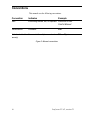
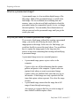
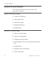
How do you find information in this manual?
This manual groups together software features that relate to
a task. Please see Figure I for a quick summary of where to
find information in this manual.
For information about:
The plug-in, in general
Please read:
Chapter 1
How to prepare for a scanning session Chapter 2
What to do before you prescan
Chapter 3
How to specify the size of a final image Chapter 4
How to tone a digital image
Chapters 5 & 6
How to create a final image
Chapter 7
Figure 1: Overview of manual
ii
Leaf scan 35 / 45, version 2.1
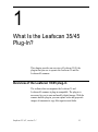
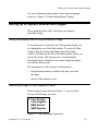
Conventions
This manual uses the following conventions:
Convention
Indicates
Italic
Example
Word being defined, title, or emphasis Leafscan 35/45
User's Manual
Helvetica bold
Command
File
Helvetica bold with
arrow(s)
Command with multiple menu levels
File Û Open
Figure 2: Manual conventions
iii
Leaf scan 35 / 45, version 2.1
1
What Is the Leafscan 35/45
Plug-In?
This chapter provides an overview of Leafscan 35/45, the
plug-in that you use to operate the Leafscan-35 and the
Leafscan-45 scanners.
Overview of the Leafscan 35/45 plug-in
The software that accompanies the Leafscan-35 and
Leafscan-45 scanners is plug-in compatible. The plug-in is
necessary for you to scan and modify digital images. With the
scanner and the plug-in, you can capture color and grayscale
images of transmissive copy like negatives and slides.
Leafscan 35 / 45, version 2.1
1-1
What is the Leafscan 35145 Plug-In ?
Overview of workflow
The following tasks provide an overview of how to use the
plug-in:
1. Capture a prescanned image of the subject.
A prescanned image is a draft image that you modify
before you capture a final image.
2. Modify the prescanned image by giving it a size and
changing its tonal qualities.
3. Capture a final image of the subject.
In actual use, each of these tasks consists of several steps,
some of which are required and some of which are optional.
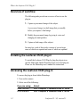
Installing the Leafscan 35/45 plug-in
To install the Leafscan 35/45 Plug-In, drag the plug-in icon
into the folder that Adobe Photoshop looks in to find plug-ins.
Please see the Photoshop user's manual for instructions.
Accessing the Leafscan 35/45 plug-in
To access the plug-in from Adobe Photoshop:
1. Turn on the scanner.
2. Select one of the following:
If you are using:
GBIB interface
SCSI interface
1-2
Select:
File Û Acquire Û Leafscan 35/45 2.1 GPIB
File Û Acquire Û Leafscan 35/45 2.1 SCSI
Leafscan 35 / 45, version2.1
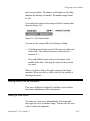
Accessing the Leafscan 35 / 45 plug-in
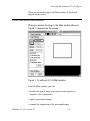
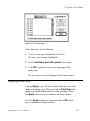
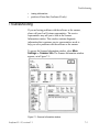
When you access the plug-in, the Main window of the plug-in
appears on the screen.
A brief look at the Main window
When you access the plug-in, the Main window shown in
Figure 1-1 appears on the screen:
Figure 1-1: Leafscan 35 / 45 Main window
From the Main window, you can:
• describe the type of image you want to create (positive or
negative, color or grayscale)
• capture a prescanned image
• examine the composition of the prescanned image
Leafscan 35 / 45, version 2.1
1-3
What is the Leafscan 35145 Plug-In?
• crop the prescanned image
• enter the size of the final image
• access the Tone window
• make a final scan
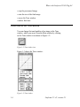
A brief look at the Tone window
You can change the tonal qualities of an image in the Tone
window, which you access from the Main window by clicking
on the Tone window icon shown in Figure 1-2:
Figure 1-2: Tone window icon
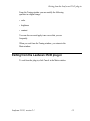
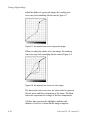
Figure 1-3 shows the Tone window:
Figure 1-3: Tone window
1-4
Leafscan 35 / 45, version 2.1
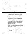
Exiting from the Leaf scan 35145 plug-in
From the Toning window you can modify the following
qualities in a digital image:
• color
• brightness
• contrast
You can also save and apply tone curves that you use
frequently.
When you exit from the Toning window, you return to the
Main window.
Exiting from the Leafscan 35/45 plug-in
To exit from the plug-in, click Cancel in the Main window.
Leafscan 35145, version 2.1
1-5
2
Preparing for a Scanning
Session
This chapter describes what to do before you begin to scan
images.
Preparing a working environment
You must establish a level of consistency in the working
environment so you can evaluate the quality of the images
you capture. Preparing a working environment involves
creating an area in which to evaluate images and adjusting
the output devices so that they represent the image
accurately. This section describes some of the issues involved
in preparing a working environment.
Leafscan35i45, version 2.1
2-1
Preparing for a Scanning Session
Creating a viewing area
The viewing area is the place where you evaluate images both
on the monitor and in print. Having a viewing area helps
compensate for the discrepancies in color between the image
on film and the image on the monitor.
The most important aspect of the viewing area is the
consistency of the lighting conditions in it. A recommended
way to view images is:
• under daylight-balanced light
• in a room with subdued lighting
Preparing the monitor
You must set the monitor to display 24-bit color (millions)
under Control PanelÛ Monitors.
Additional adjustments to the monitor help ensure that the
image on film and its digital counterpart look as much alike
as possible. After you prepare a viewing environment, adjust
the monitor so that the colors you see in an image accurately
represent the colors in the subject of the image. How you
adjust the monitor is specific to the individual monitor and to
the application you are using. Most adjustment methods fall
into two categories:
• Hardware - You can adjust the contrast and brightness by
turning knobs on the monitor.
• Software - Many image processing application packages
let you correct the monitor for color shifts in red, green or
blue phosphors.
You should not depend entirely on the monitor to evaluate
color and tone. The monitor is more capable than inks of
reproducing colors, and may therefore display colors that
2-2
Leafscan 35145, version 2.1
Selecting film format (Lieafscan-40 only)
cannot be recreated in inks. Monitors also do not represent
contrast accurately. In addition, because monitors are analog
devices, there may be slight fluctuations in the colors they
represent. Despite these limitations, monitors provide a good
guideline as to the quality of the image. You should, however,
print the image to get a true indication of its quality.
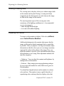
Selecting film format (Leafscan-45 only)
You select the format, or size, of the film you are scanning
only when you use the Leafscan-45. The scanner uses this
information to adjust the position of the lens to capture the
entire image.
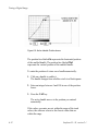
When you use a Leafscan-45, the Film Format feature opens
into a pop-up menu, as shown in Figure 2-1:
3
35mm Portrait
35mm Landscape
6 x 4.5 cm
6 x 6 cm
6 x 7 cm
6 x 9 cm
4 x 5 inch Landscape
4 x 5 inch Portrait
Maximum 1:1
Maximum 1:2
Figure 2-1: Film Format feature for Leafscan-45
Select the film size from this pop-up menu according to the
film you are scanning. When you release the mouse button,
the Film Format box displays the currently selected format.
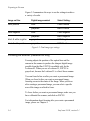
The Maximum (1:1, 1:2, and 2:1) sizes let you scan at the
maximum area attainable at each of the three magnifications
available in the Leafscan-45. These magnification settings
Leaf scan 35145, version 2.1
2-3
Preparing for a Scanning Session
can let you capture a smaller portion of a 4x5 film at a higher
resolution, or can let you use a custom-made film holder.
Figure 2-2 lists the specifications for the Maximum settings:
Film Format: DPI:
Area:
# of Pixels:
Approximate
File Size:
Maximum 1:1
2540
6 cm x 12.7 cm
6000 x 12700
228 Mb
Maximum 1:2
1200
12.7 cm x 12.7 cm
6000 x 6000
108 Mb
Maximum 2:1
5080
3cmx 12.7 cm
6000 x 254000
436Mb
Figure 2-2: Specifications for maximum film format settings
Calibrating the scanner
Calibration is a mechanical and mathematical process that
occurs in the scanner to compensate for differences in the way
the scanner reads light. During calibration, exposure times
and ranges are determined.
Calibration is necessary under these conditions:
• about 15 minutes after you turn on the scanner to
compensate for bulb drift
Bulb drift occurs when the bulb in the scanner warms up,
thereby changing brightness. When the brightness
changes, the scanner needs to be adjusted (calibrated) to
produce a quality image. Bulb drift occurs most rapidly
and radically during the first 15 minutes after you turn on
the scanner.
• about every two hours to compensate for bulb drift
• always before you do your first prescan
The Prescan button is grayed-out until you calibrate the
scanner.
2-4
Leafscan 35 / 45, version 2.1
Calibrating the Scanner
• For Leafscan-45 only: each time you change the film size
setting on the Film Format pop-up menu (described
previously)
How to calibrate
To calibrate the scanner:
1. Turn on the scanner and wait about 15 minutes for the
scanner and bulb temperature to stabilize.
2. (Leafscan-45 only) Select format of film.
3. Click on Calibrate.
A prompt reminds you to remove the film holder from the
scanner.
4. Remove the film holder, if one is present.
5. Click OK in the dialog box.
The calibration process begins. You may see a message telling
you to open or close the f-stop of the scanner lens. In this case,
adjust the scanner lens as the message suggests and click on
Calibrate again. When the messages cease, the calibration
process ends.
What happens after you calibrate a Leafscan-35
After you calibrate the Leafscan-35, Prescan is enabled.
What happens after you calibrate a Leafscan-45
After you calibrate the Leafscan-45, Prescan and Focus are
enabled.
Leafscan 35 / 45, version 2.1
2-5
Preparing for a Scanning Session
Cancelling calibration
You may want to cancel calibration if you realize that the film
holder is in the scanner or if you discover that the film format
setting is incorrect.
To cancel out of the calibration process, press the Apple key
and the period(.). After a few seconds, calibration halts.
Adjusting Exposure
Exposure lets you control the length of time that film is
exposed to light through each color filter. The exposure
feature lets you compensate for film that is not correctly
exposed or processed. Exposure settings also let you reduce
scanning time.
You set exposure in the Exposure Time window. To access the
Exposure window, select More Settings -*- Exposure Time
from the Main window. The Exposure Time window appears,
as shown in Figure 2-3:
Figure 2-3: The Exposure Time window
2-6
Leafscan 35 / 45, version 2.1
Adjusting exposure
Exposure settings are interrelated. A change to one setting
may affect the others.
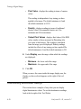
Reading an exposure slider
Exposure values for each filter are recorded on sliders as in
Figure 2-4:
Figure 2-4: An exposure slider
The filter identifier indicates the filter that the slider
represents:
• R (red)
• G (green)
• B (blue)
• B&W (neutral density)
The numbers on the slider, which range from -3 to +3,
represent the range of exposure settings. Think of exposure
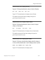
settings as f-stops. Figure 2-5 shows the relationship of
exposure settings to actual exposure time in milliseconds.
Leafscan 35 / 45, version 2.1
2-7
Preparing for a Scanning Session
Exposure Setting Exposure Time
0
optimum time (determined by calibration process)
-1
half the optimum exposure time
-2
one fourth the optimum exposure time
-3
one eighth the optimum exposure time
+1
two times the optimum exposure time
+2
four times the optimum exposure time
+3
eight times the optimum exposure time
Figure 2-5: Relationship of exposure settings to exposure time
The triangle marks the current exposure setting. The triangle
is always located between the dotted vertical lines. The dotted
vertical lines represent the available exposure range settings
for a particular image. The calibration process determines
this range.
The Current field indicates the exposure time associated
with the current setting in the slider.
The Optimum field always records the optimum exposure
time value of the 0 setting. Zero is the exposure setting that
represents optimum exposure time. Optimum exposure time
is determined by the calibration process.
The letting indicator is located over each slider.
• If you select Optimum, the setting indicator is set to
Optimum on all the sliders.
• If you select either Minimum or Custom, the setting
indicator displays a number that indicates the exposure
setting, or placement of the triangle on the slider.
2-8
Leafscan 35 / 45, version 2.1
Adjusting Exposure
Using Optimum and Minimum exposures
To use either Optimum or Minimum, click on the radio button
next to one of these settings. Try using Minimum before
Optimum. Try Minimum and Optimum before Custom.
Optimum
Optimum sets the exposure of all the filters to zero, the
optimum exposure time determined by calibration.
The Optimum setting gives the best balance of dynamic range
and scanning time.
Minimum
Minimum sets the exposure of all filters to the lowest setting
available in the exposure range.
This setting is recommended for most film that does not have
exposure or development problems. This setting takes less
time to scan than the Optimum setting.
The Minimum setting slightly reduces the dynamic range of a
scan from approximately 3.7 to 3.0 to decrease scanning time.
However, the dynamic range of a digital image scanned at
minimum exposure may still exceed the dynamic range of the
film. As a result, the quality of the digital image most likely
remains high, although the amount of time it takes to scan
the image is greatly reduced.
Using Custom exposure
Whenever you drag the triangle on any individual slider, the
Custom setting becomes active. Use this setting when the
Leafscan 35 / 45, version 2.1
2-9
Preparing for a Scanning Session
result from the Optimum setting does not produce an image
with the effect you want.
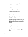
Procedure for setting exposure
To set exposure:
1. Calibrate the scanner.
You cannot set exposure until you calibrate.
2. Select from the Main window:
More Settings Û Exposure Time
The Exposure window appears.
3. Select one of the following exposure settings:
•
Minimum - to use the minimum exposure value in the
exposure range
•
Optimum - to maintain exposure values from the
original calibration for all filters
•
Custom - to adjust the exposure of each individual
filter.
The setting you select remains in effect even after you
recalibrate. Try using the exposure settings in this order:
Minimum, Optimum and Custom. You may seldom need to
use Custom.
2-10
Leaf scan 35 / 45, version 2.1
3
Preparing to Prescan
This chapter explains the concept of a prescanned image and
describes what to do before you capture one. Depending on
what you want to accomplish, you may need to do these tasks
each time you capture a prescanned image or set up once for a
group of images.
Understanding the prescanned image
Capturing images involves creating and modifying a
prescanned image. Once you finish modifying the prescanned
image, you can capture a final image that incorporates the
modifications you made to the prescanned image.
Leafscan 35 / 45, version 2.1
3-1
Preparing to Prescan
What is a prescanned image?
A prescanned image is a low-resolution digital image of the
film image. Think of the prescanned image as a draft of the
final image. The low resolution saves scanning time and
memory, since you do not need high resolution to check the
prescanned image for composition, specify its size, or change
the tonal qualities. You can modify these characteristics as
often as you need on the prescanned image until you get the
results you want.
Why do you need to create a prescanned image?
If you create a final image without first creating a prescanned
image, you run the risk of having the tonal values be
inappropriate to the image. In the case of a final image, you
would not be able to correct the tonal values. You would then
have to capture the image again. In the long term, this
process is more time consuming than creating and modifying
a prescanned image.
A prescanned image serves two essential purposes:
•
•
A prescanned image passes capture values to the
computer.
Capture values are all the information that the scanner
gathers and passes to the computer. Capture values are
captured only when you create a prescanned image.
Capture values are translated into tones that you see on
the monitor. A final image uses only a portion of all the
tones that capture values represent. You select the range
of tones.
A prescanned image ensures that the image has a full
range of tones through autoranging.
Autoranging is a process that lets you select a range of
tones from all available capture values.
3-2
Leaf scan 35145, version 2.1
Setting up to capture prescanned images
For more information about capture values and autoranging,
please see Chapter 5. (Understanding Digital Toning),
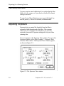
Setting up to capture prescanned images
This section describes what to do before you capture a
prescanned image.
Sizing the display area of the prescanned image
You can increase or reduce the size of the prescan display area
by changing the size of the Main window. To resize the Main
window, drag the bottom right hand corner of the Main
window. You must set the size of the Main window before you
prescan the image. After the prescan is executed and the
prescanned image is displayed, you cannot change the display
size until the next prescan.
The maximum size of the window is determined by:
•
the application memory available at the time you create
the image
•
the size of the monitor screen
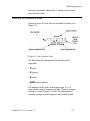
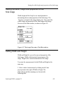
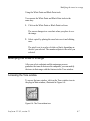
Selecting the type of final image you want
From the pop-up menu shown in Figure 3-1, you can select
the type of final image you want:
3 Color Positive
Color Negative
B&W Positive
B&W Negative
Figure 3-1: The Final image Type menu
Leafscan 35 / 45, version 2.1
3-3
Preparing to Prescan
Figure 3-2 summarizes the ways to use the settings to achieve
a variety of results.
Image on film:
Digital image wanted:
Select Setting:
color positive
color
Color Positive
grayscale
B&W Positive
color
Color Negative
grayscale
B&W Negative
black & white negative
grayscale
B&W Negative
black & white positive
grayscale
B&W Positive
color negative
Figure 3-2: Final image type settings
Focusing the scanner (Leafscan-45 only)
Focusing adjusts the position of the optical lens and the
camera in the scanner to produce the sharpest digital image
possible from the film. FOCUS is available only for the
Leafscan-45. When you use a Leafscan-35, FOCUS is
grayed-out, because the Leafscan-35 is a fixed focus scanner.
You can focus before or after you create a prescanned image.
When you focus before you create a prescanned image,
focusing occurs in the center of the image. When you focus
after creating a prescanned image, you can select a specific
area of the image on which to focus.
To focus before you create a prescanned image, make sure you
have calibrated the scanner, and click on FOCUS.
For information about focusing after you create a prescanned
image, please see Chapter 4.
3.4
Leaf scan 35145, version 2.1
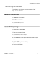
Summary: Capturing a prescanned image
Summary: Capturing a prescanned image
To create a prescanned image:
1. (Leafscan-45 only.) Select the film format. (Please see
Chapter 2.)
2. Calibrate the scanner. (Please see Chapter 2.)
3. (Optional) Set exposure. (Please see Chapter 2.)
4. (Optional) Set the image display size.
5. Select the final image type you want from the Final Image
Type pop-up menu.
6.
(Optional - Leafscan-45 only.) Focus the scanner.
7. Click on Prescan.
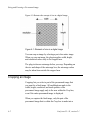
As the scanner captures the image of the subject, the image is
displayed on the monitor. Because the image has a low
resolution, it may appear soft. A blue box surrounds the area
of the image where the autorange selects values.
The plug-in offers features and tools that you can use to
enhance the image. Chapter 4 (Sizing an Image) and Chapter
6 (Toning a Digital Image) describe these features.
Leafscan 35 / 45, version 2.1
3-5
4
Sizing and Focusing a
Prescanned Image
This chapter describes how to assign a size to and focus a
digital image.
Understanding size in digital images
Digital images have no inherent physical size like images on
35 mm or 4x5 film. You must specify the size of the image in
terms of resolution, width, and height. Width and height
determine the area and proportion of the final image.
Resolution determines the amount of pictorial information
within the area.
Leafscan 35 / 45, version 2.1
4-1
Sizing and Focusing a Prescanned image
Figure 4-1 illustrates the concept of size in a digital image:
Figure 4-1: Elements of size in a digital image
You can crop an image by selecting a part of an entire image.
When you crop an image, the plug-in applies width, height,
and resolution values only to the cropped area.
The plug-in does an autorange before you crop. Depending on
the size and shape of the autorange box, the autorange values
may be taken from outside the cropped area.
Cropping an image
Cropping lets you select a part of the prescanned image that
you want for a final image. All modifications made to the
width, height, resolution, and tonal qualities of the
prescanned image apply only to the area within the Crop box,
even if the entire prescanned image is displayed.
When you capture the final image, only the part of the
prescanned image that is within the Crop box is made into a
4-2
Leaf scan 35 / 45, version 2.1
Cropping an image
final image. If you plan to modify the prescanned image,
cropping is the first modification you should make.
How to crop a prescanned image
To crop a prescanned image:
1. Click on the Crop tool in the tool palette, as shown below:
2. Locate the Crop box:
• If you have just prescanned the image, the Crop Box is
located at the very edge of the display area. You may
not see it until you click on it.
• If you have reloaded a previously saved prescanned
image, the Crop box is in the position it was in when
you made the final scan.
3.
Resize and move the Crop box to a part of the image that
you want to be the final image.
•
To reduce or enlarge the Crop box:
Position the mouse cursor on a border of the Crop box.
The cursor changes to a double headed arrow. Drag the
cursor to increase or decrease the size of the box.
•
To move the Crop box:
Place the cursor inside the Crop box. The cursor
changes into two crossed, double-headed arrows. Drag
the cursor until the Crop box is in the position you
want.
Leafscan 35 / 45, version 2.1
4-3
Sizing and Focusing a Prescanned Image
Remember that all future modifications apply only to the area
of the image within the Crop box.
Isolating the cropped area
You can better visualize the effects of the cropping by
isolating the cropped area from the entire image. To isolate
the cropped area, hold down the OPTION key. The area
outside of the Crop box in the display area turns gray. When
you release the OPTION key, you can see the original
contents of the display area.
Creating a prescanned image of the cropped area only
A prescanned image of the cropped area is as large as the
original, uncropped image. Creating a prescanned image of
the cropped area is recommended because the cropped area is
larger and easier to evaluate.
To create a prescanned image of the area within the Crop box:
1. Hold down the Option key.
The area outside the Crop box turns gray. Prescan
changes to Cropped.
2. Click on Cropped.
Only the area within the Crop box is captured as a
prescanned image.
4-4
Leafscan 35 / 45, version 2.1
Setting the width, height and proportion of the final image
Setting the width, height and proportion of the
final image
Width, height and the Crop box are interdependent in
determining the area and proportion of the final image. The
Crop box is located in the image display area. You control the
width, height, and proportion of the final image in the Image
Size area of the Main window, as shown in Figure 4-2:
Figure 4-2: The Image Size area of the Main window
Setting Width and Height
Width and Height let you set the area and proportion of the
final image. Width is the horizontal measurement of the
image. Height is the vertical measurement of the image.
You enter the measurements for both Width and Height in the
same way:
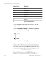
1. Select a unit of measurement by clicking on the Units
pop-up menu to the right of Width or Height. The
abbreviations and their meanings are shown in the
following table:
Leaf scan 35145, version 2.1
4-5
Sizing and Focusing a Prescanned Image
Abbreviation:
Meaning:
in
inch
cm
centimeter
mm
millimeter
pc
pica/point
cc
cicero
co
column
%
width as a percentage
2. Type the number of units in the box to the left of the Units
pop-up menu.
3. Lock either Width or Height, by clicking on the open lock
icon next to the dimension. The open lock icon changes
from open to closed, as shown below:
unlocked
locked
- User Tip You can type the number of units and the unit measurement
directly in the box.The unit measurement automatically changes.
For example, when you type 27 mm in the unit box, the unit of
measurement changes to mm without your having to select mm
from the pop-up menu.
When you lock either dimension, Final Scan becomes
highlighted. At this point you can capture a final image of the
4-6
Leaf scan 35 / 45, version 2.1
Setting the width, height and proportion of the final image
area within the crop box, or you may capture another
prescanned image of the entire area. Please see page 4-10 for
information about combining the Crop box with Width and
Height settings.
Using Columns (co) as a unit of measurement
Use columns (CO) as a unit of measurement when you want
the size of the digital image to fit into a predetermined
column size. You may find this feature convenient when you
scan images for a newspaper or magazine whose format
includes columns. To use columns as a unit of measurement,
you set the dimensions of the column and then select CO in the
Image Size area to represent that dimension.
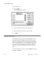
To set the dimension of the Columns unit:
1. Select More Settings Û Columns.
The Columns Preference window appears:
2. Under Width of one column, select a unit of measurement
from the pop-up menu on the right, and enter the number
of units in the box to the left of the pop-up menu.
3. Under Space between columns, select a unit of
measurement from the pop-up menu on the right, and
Leafscan 35 / 45, version 2.1
4-7
Sizing and Focusing a Prescanned Image
enter the number of units in the box to the left of the
pop-up menu.
4.
Click OK.
The Columns Preference window disappears.
5. In the Image Size area, select CO as a unit of measurement
for either Width or Height and enter the number of
columns to represent the size of the image.
When you enter I column, the image size is the measurement
of a single column. When you enter more than one column,
the image size is the measurement of all the columns plus the
measurement of the spaces between the columns.
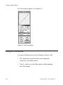
As an example of using CO as width, assume that:
•
The width of one column is 3 inches.
•
The space between columns is .25 inches.
•
The image size is 3 columns wide and 10 inches high.
The image size is calculated to fit as shown in Figure 4-3:
Figure 4-3: Using columns as width
4-8
Leafscan 35 / 45, version 2.1
Setting the width, height and proportion of the final image
As an example of using CO as height, assume that:
•
The width of one column is 3 inches.
•
The Space between columns is .25 inches.
•
The image size is 3 columns high and 10 inches wide.
The image size is calculated to fit as shown in Figure 4-4:
Figure 4-4: Using columns as height
Using a percentage (%) for the width dimension
Use the % option to specify the width dimension of a final
scan as a percentage of a known size, instead of an absolute
measurement. The percent you enter for width is applied to
the height to maintain aspect ratio.
If, for example, you are scanning a 4" x 5" transparency and
want the size of your final scan to be 8" x 10", select % in the
Unit pop-up menu, and then enter 200 (%) in Width. The final
image will be twice as large as the original slide.
The percent figure applies only to the currently cropped area.
Leafscan 35 / 45, version 2.1
4-9
Sizing and Focusing a Prescanned Image
Combining Crop Box, Width and Height Settings
This section describes how to combine the Crop box, Width
and Height settings to control the image size and proportion.
The relationship of the Crop box to the Width and Height
settings in the Image size area is the following:
•
If Width or Height are locked, the crop box maintains the
proportion of the locked dimension(s).
•
If neither Width nor Height are locked, the Crop box can
take any proportion. Once you have the proportion you
want in the Crop box, enter and lock a value into either
Width or Height. The other dimension updates to preserve
the proportion of the Crop box.
Imposing a proportion on the Crop box
To force the Crop box into a fixed proportion, in spite of its
size, lock both Width and Height values. The horizontal and
vertical dimensions of the Crop box also lock in the proportion
you specify in the Width and Height values. In this case, you
can move, enlarge and reduce the Crop box, but you cannot
change its proportion by clicking and dragging on its
boundaries.
For example, assume the following:
•
Width is locked at 2 inches
•
Height is locked at 4 inches
The horizontal and vertical measurement of the Crop box will
always reflect the 1:2 proportion that is established by the 2
inches by 4 inches. You can make the Crop box bigger or
smaller to capture more or less of the prescanned image, but
the proportion of the Crop box remains 1:2 at any size.
4-10
Leaf scan 35 / 45, version 2.1
Setting Resolution
Resizing the Crop box freely
To shape the Crop box into a rectangle of any proportion, do
not lock either Width or Height.
When you have cropped the image as you want, enter a value
in Width or Height, and lock the value. The other value
automatically updates, and the proportion of the final image
that you set with the Crop box is preserved.
Imposing proportion in one dimension of the Crop box
If you lock either Width or Height, the unlocked setting
automatically recalculates to maintain the proportion of the
Crop box.
For example, assume the following:
•
Width is locked at 2 inches.
•
Height is not locked.
The Crop box assumes that its width is always 2 inches,
regardless of how wide or narrow it appears on the display
area. When you resize the Crop box, the height is recalculated
on the assumption the Width is 2 inches.
Setting Resolution
This section defines resolution and describes how to enter a
resolution value.
Leafscan 35 / 45, version 2.1
4-11
Sizing and Focusing a Prescanned Image
What is resolution?
Resolution is a measure of the amount of pictorial information
that the scanner reads and that the output device uses to
produce a final image. Resolution is measured in dpi (dots per
inch) or ppm (pixels per millimeter).
Dots and pixels are two names for the same object, a picture
element. In an image, a pixel displays a color that
corresponds to a small area in the subject.
How does resolution affect images?
Resolution does not affect the height or width of an image.
You can have a I inch by I inch image with 72 dpi, 100 dpi,
300 dpi, and so on. Resolution does affect the amount of detail
that you can see within the area of the image, as shown in
Figure 4-5:
Figure 4-5: Low, medium, and high resolution images. Photograph courtesy of
David Perdew/Stock South.
4-12
Leafscan 35 / 45, version 2.1
Setting Resolution
In general, an image with low resolution has less detail and
more contrast. An image with high resolution has more detail
and less contrast.
How does resolution affect the way an image is displayed?
The scanner, monitor, and printer have different capabilities
of representing images with different amounts of resolution
(different measurements of dpi).
The scanner captures information at a maximum resolution
that depends on the scanner model, selected film format, and
magnification. To create a lower resolution, the scanner can
force two or more adjacent pixels to act as one pixel. This
process is called averaging,
The monitor displays an image at a resolution that is equal to
or less than the resolution the scanner used to capture the
image. The image still has all the resolution that the scanner
used to capture it - the monitor displays only a part of all
available information.
The printer also has an inherent resolution. To find the range
of resolution that your printer is capable of processing, please
read the printer manual. Scan the image at a resolution that
is compatible with the printer.
Entering resolution
To enter the resolution of the final image:
1. Select either dpi or ppm from the Units pop-up menu at
the right of Resolution.
2. Type the number of units in the Resolution box.
Resolution, like width and height values, applies only to the
final image.
Leafscan 35 / 45, version 2.1
4-13
Sizing and Focusing a Prescanned Image
The maximum amount of resolution that you can enter
depends on the width, height and the area within the Crop
box. If the resolution you enter exceeds what these values can
allow, the plug-in automatically recalculates the maximum
resolution at which the scanner can scan. The plug-in then
replaces your entry with this value.
Determining how much disk space a final image requires
The plug-in automatically calculates the amount of disk space
that an image requires for storage, based on area and
resolution. The larger the area and the greater the resolution,
the more space the image requires. To have these numbers
automatically calculated, you must lock Width, Height, or
both.
This calculation is displayed in the upper right hand corner of
the Image Size area, as shown in Figure 4-6.
Figure 4-6: The image size display
The first number (1663
1663) represents the number of pixels in
the width of the final image. The second number (2000)
represents the number of pixels in the height of the final
image. The resulting third number (9.5MB) represents the
total amount of disk space that the final image requires for
storage.
4-14
Leafscan 35 / 45, version 2.1
Balancing image quality and size
Balancing image quality and size
This section suggests how to combine width, height, cropping
and resolution for specific situations.
To have a good balance between the detail in an image and
the amount of memory necessary to store the image, you can
do a combination of the following:
•
Select resolution according to the output device.
• Crop the prescanned image to be as much like the final
image as possible.
An efficient strategy for creating a digital image is to prepare
the prescanned image to be as much like the final product as
it can be before you do a final scan. The following are some
effective ways of compromising between image quality and
disk space.
If you know the size of the final image
Set the width and height of the final image before you scan it,
rather than cropping it or reducing it after afterwards.
If you do not need to use the entire image
Select (crop) the part of an image you want and then do a final
scan on that part only.
If you are printing with a halftone screen
If the output is printed in halftones, a factor in determining
resolution is the ruling of the halftone screen you use to print
the image. A rule of thumb is to double the screen ruling to
Leafscan 35 / 45, version 2.1
4-15
Sizing and Focusing a Prescanned Image
get an appropriate resolution. For example: If the screen
ruling is 85 lines per inch, use a resolution of 170 dpi.
If you are calculating image size in pixels for film recorders
Image sizes for film recorders are most accurately calculated
in pixels.
To set an image size in pixels:
1. Determine which image dimension is more important to
the placement of the image: width or height.
2. Enter I" for the dimension that is more important, either
Width or Height, and lock the value.
3. Enter the resolution you require in Resolution.
4. Press TAB to update the value of the unspecified
dimension.
The numbers in the top right corner of the Image Size area
show the total number of pixels that will be in the final
image. You can now adjust the Crop box to get the exact
number of pixels for the dimension that you did not lock.
For example, assume that you want to create a final image
and output it to a 4K film recorder. The subject can be of any
size. For highest quality, the final image must have 4000
pixels across the width. To get the correct size:
1. Enter I" in Width (the more important dimension), and
lock the value.
2. Enter 4000 in Resolution.
3. Press TAB.
The top-right corner of the image size box will have numbers
similar to these: 4000 x 3005 = 34.4 MB. You can now adjust
the size of the Crop box to get closer to the exact number of
pixels that you require for Height.
4-16
Leafscan 35145, version 2.1
Focusing an Image (Leafscan-45 scanner only)
If you do not know how the image will be used in the future
If you cannot determine how an image will be used, scan the
entire image at the highest resolution you are likely to
need.This method works well if you are archiving images
whose future use is currently undefined. However, this
method does take up more disk space.
The highest resolution at which you can save a final image is
16 bits. To save a final image with 16-bit resolution, select
More Settings Û 16 bit.
When you select the 16 bit format, a check mark is posted
beside the setting to indicate that is active. The 16 bit setting
remains active until you turn it off.
Focusing an Image (Leafscan-45 scanner only)
After you have cropped the prescanned image, you may want
to focus on a specific part of the image. Focusing adjusts the
lens position in the scanner to produce the sharpest image
possible.
Focus is available only for the Leafscan-45. When you use a
Leafscan-35, Focus is grayed-out.
When you focus after creating a prescanned image, you can
select a specific area of the image on which to focus. (For
information about focusing before you create a prescanned
image, please see Chapter 3.)
When to focus
You must focus the Leafscan-45:
Leafscan 35 / 45, version 2.1
4-17
Sizing and Focusing a Prescanned Image
•
whenever you change film size setting (Film Format
feature)
When you select a new film size, the scanner lens and
camera board shift to accommodate the size of the new
image.
•
when you change to a different film holder
When you change film holders, the thickness of the holder
changes the position of the film plane (even if you keep the
same film).
•
when you change f-stops on the scanner lens
You may want to focus the Leafscan-45 scanner:
•
when a prescanned image or final image seems out of focus
•
before each final scan of an image to ensure that the image
will be as sharp as possible
•
when you have a specific area of the image on which you
want to focus
How to focus on a part of a prescanned image
To focus on a part of a prescanned image:
1. Click on the FOCUS tool, located in the tool palette:
A green horizontal line appears over the prescanned
image. This line represents the area of the image on which
the scanner focuses.
4-18
Leafscan 35 / 45, version 2.1
Focusing an Image (Leafscan-45 scanner only)
2.
Drag the green line to a part of the prescanned image on
which you want to focus - ideally, an area with high
contrast. This area should contain some detail.
3. Click on Focus.
When you first open the plug-in, the default position of the
focus line is the center of the image. Once you change the
position of the line, focusing continues in the new position
until you:
• move the line to a new position
• click on Reset
• change the film format
Leafscan 35 / 45, version 2.1
4-19
5
Understanding Digital
Toning
This chapter describes concepts associated with digital toning
as it relates to this product. If you are not familiar with
digital toning, this chapter may provide you with the
foundation with which to make intelligent decisions about
toning.
If you are already familiar with digital imaging, you may
want to skim through this chapter and go to Chapter 6,
Toning a Digital Image.
Leaf scan 35 / 45, version 2.1
5-1
Understanding Digital Toning
What is toning?
Toning is the process of adjusting the following properties in a
a prescanned image:
•
contrast
•
•
brightness
color
You tone a prescanned image by:
1. Selecting the lightest and darkest tones you want in the
image.
The plug-in then automatically calculates the values
in-between these points into a 256-value tonal range.
2. Modifying the tones between the range.
These tasks consist of several steps that are described
Chapter 6.
Why do you tone an image?
Toning helps you produce a better image by letting you adjust
color in an image. In a digital image, toning also lets you
select a range of tones that is appropriate to the image.
Selecting a range is necessary because the scanner transfers
more tonal data than most computer systems can display. The
tonal data is called capture values.
Toning a prescanned image instead of a final image gives you
the advantage of being able to work with the capture data
instead of a limited 256 range. Working with the capture data
gives you a greater dynamic range and more control over the
light and dark areas of the image.
5-2
Leaf scan 35 / 45, version 2.1
Understanding capture values and final values
Toning a prescanned image eliminates the need for much
post-production color correction, which can be time
consuming and costly. You can make the color corrections and
immediately see the results.
Understanding capture values and final values
Capture values are all the information that the scanner
gathers and passes to the computer. Capture values are
gathered only when you capture a prescanned image. Capture
values are represented as tones of color or shades of gray on
the monitor.
Understanding capture and final values is important because
each tone is assigned a numeric equivalent. Because of
limitations in the way monitors display color, the numeric
equivalent is a more accurate way of determining if a tone is
accurate. When you click on a tone in the image, its numeric
value is displayed in the densitometer.
The scanner transfers more capture values than most
computer systems can display as tones. The scanner gathers
16 bits of capture values. In other words:
•
65,536 tones of red
•
65,536 tones of green
•
65,536 tones of blue
Although all the capture values of the prescanned image are
stored in memory, the monitor image displays only 8 bits of
the values at one time. In other words:
•
256 tones of red out of 65,536 capture values
•
256 tones of green out of 65,536 capture values
•
256 tones of blue out of 65,536 capture values
Leaf scan 35 / 45, version 2.1
5-3
Understanding Digital Toning
The final image inherits only the 256 tones per color that are
displayed on the screen. Through autoranging and toning,
you can select and modify the range of tones.
Understanding autoranging
Autoranging is a mathematical process that selects a range of
256 tones from the 65,536 capture values. The 256 values are
the tones you see on the monitor. Autoranging works by:
1. determining the lightest and darkest capture values in an
area of the image
2. making the lightest value white and the darkest value
black
3. graduating all the values in-between white and black
When you capture a prescanned image, the autorange process
automatically occurs on the capture values. The lightest and
darkest points are automatically selected from within the
blue autorange box. The size and position of the box are
initially a default. If you do not like the tonal qualities that
result from the autorange, you can move the box or use other
methods to select a black and white point. (Please see
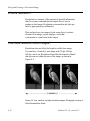
Chapter 6.)
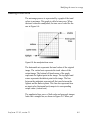
Autoranging permits each range of 256 tones to include
highlights, midtones, and shadows. Figure 5-1 on the following
page illustrates the concept of selecting a range of tones from
capture values.
5-4
Leaf scan 35 / 45, version 2.1
Understanding autoranging
Figure 5-1: Concept of selecting a range of final tones from capture values
through autoranging
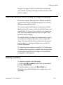
When capture values are converted into final values, the
result is that one final value may represent more than one
capture value. Figure 5-2 depicts a conceptual representation
of a how more than one capture value is assigned to one final
image value.
Capture values:
Final value:
10,291-10,361
201
10,363-10,440
202
Figure 5-2: Concept of capture values being converted into final values
Leaf scan 35 / 45, version 2.1
5-5
Understanding Digital Toning
How do pixels represent color?
This section describes how the monitor represent color
through pixels and how the plug-in controls that process.
How pixels represent tones
The plug-in assigns a component in each pixel to represent a
tone. This plug-in assigns each pixel three color components:
red, green, and blue. The plug-in then combines these
components in different intensities to represent a color. In
other words, one color component can represent many tones.
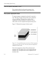
Figure 5-3 illustrates the concept of color in a pixel:
Figure 5-3: Conceptual illustration of a color pixel. Each component
represents many tones of its color. One tone from each component is
combined to create a color.
Each color component in each pixel has a minimum and a
maximum value. The darkest tone in each component has the
minimum value. The lightest tone in each component has the
maximum value.
5-6
Leaf scan 35 / 45, version 2.1
How do pixels represent color?
Figure 5-4 summarizes the values of the different color
components when a pixel represents color:
Tone
Value of color component
pure black All color components have the minimum value.
pure white All color components have the maximum value.
color
At least one component has a different value than
the other two components. The value may need to
be significantly different from the others for the
human eye to perceive the color.
Figure 5-4: Component values in pixels representing tones
A pixel in which the red, green, and blue components have the
same value is called neutral, or gray.
How pixels represent shades of gray
In a black and white image, the plug-in assigns each pixel one
component that represents white, black, and shades of gray.
In other words, the entire pixel becomes one component.
Figure 5-5 summarizes the values of the component when a
pixel represents shades of gray:
Shade
Value of component
pure black The component has the minimum value.
pure white The component has the maximum value.
gray
The component has a value between the minimum
and the maximum, exclusive. The value may need
to be significantly different from the others for the
human eye to perceive the shade of gray.
Figure 5-5: Component values in pixels representing shades of gray
Leafscan 35 / 45, version 2.1
5-7
Understanding Digital Toning
What determines minimum and maximum pixel values
The numeric values of pixel components are first determined
by how much pictorial information the pixels in the scanner
capture and transfer to the computer.
The scanner captures a maximum number of:
•
65,536 values of gray, including black and white in a
grayscale image (16 bits per shade)
•
65,536 values of red 65,536 values of green, and 65,536
values of blue in a color image (16 bits per color)
These values are called capture values. When pixels represent
capture values, the maximum component value is 65,536
(white) and the minimum component value is 0 (black).
Most computer systems can display only 256 tones or shades
from the capture values of 65,536 per component. The 256
values are called final values (8-bit). When a pixel represents
final values, the maximum component value is 255 (white),
and the minimum component value is 0 (black).
5-8
Leaf scan 35 / 45, version 2.1
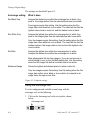
6
Toning a Digital Image
This chapter describes how to change the tonal quality of a
prescanned image. If you are not familiar with digital toning
principles, please read Chapter 5.
Overview of toning tasks
The following tasks are basic to toning:
1. Selecting the endpoints of a tonal range.
2. Modifying the tones between the endpoints.
These tasks consist of several steps that are described in the
following sections.
Leaf scan 35 / 45, version 2.1
6-1
Toning a. Digital Image
Selecting Endpoints
Selecting endpoints is the first step in the color correction
process. Endpoints are the lightest and darkest tones you
want in the final image.
When you capture a prescanned image, endpoints are selected
with an autoranging process that occurs automatically. The
area from which the endpoints are selected is within the blue
autorange box in the image display area. The default position
of this box is the center of the image.
If, after the prescanned image is autoranged, you do not like
the resulting tonal qualities, you can select another set of
endpoints by doing one of the following:
•
moving the autorange box to another area of the image
•
selecting a light tone and a dark tone manually
Selecting endpoints with the autorange tool
When you use the autorange tool to select endpoints, you do
not have to select two separate tones to represent the lightest
and darkest endpoints of the tonal range. The tool
automatically selects them from within the area you specify.
Selecting an area to autorange
Make sure that the area of the image you select for
autoranging does not include:
6-2
•
specks of dust or dirt
•
defects in the film or emulsion
•
specular highlights or extremely dark shadows
Leaf scan 35 / 45, version 2.1
Selecting Endpoints
Any of these elements may skew the tonal range that results
and make the highlights and shadows difficult to control.
Selecting how autoranging assigns values to endpoints
The autorange selection area lets you select how you want the
autorange process to assign values to the endpoints. Once you
choose a setting, all future autorange processes, both manual
and automatic, are carried out with that setting until you
change the setting again.
The autorange selection area appears in the same place as the
Image Size area when you select the autorange tool from the
tool palette. The autorange selection area is shown in Figure
6-1:
Figure 6-1: The autorange selection area
When you set the film format to either Color Positive or
Color Negative, you can click on any of the settings in the
autorange selection window. When you set the film format to
either B&W Positive or B&W Negative, the settings in
autorange selection area are grayed-out. The reason is that all
settings have the same effect on black and white images.
Leaf scan 35 / 45, version 2.1
6-3
Toning a Digital Image
The settings are described Figure 6-2:
Autorange setting:
What it does:
Set Black Only
Assigns the darkest tone within the autorange box to black. Any
pixel in the image darker than the selected pixel also turns black.
Few images require this setting. Use this setting when the film
image has a true black but no true white. The result will be that the
lightest colors retain a color tint, and the darkest color is black.
Set White Only
Assigns the lightest tone within the autorange box to white. Any
pixel in the image lighter than the selected pixel also turns white.
Very few images require this setting. Use this setting when the film
image has a true white but no true black. The result will be that the
darkest colors in the image retain a color tint and the lightest color
is set to white.
Set Both
Assigns the lightest tone within the autorange box to white.
Assigns the darkest tone within the autorange box to black.
Most photographs fall into this category. If you are not sure as to
which setting to use, try the Set Both setting first. Use this setting
when the film image has both a true black and a true white.
Maximum Range
Allows the lightest and darkest pixels to retain a color tint.
Very few images require this setting. Use this setting when the film
image has neither a true black or a true white. An example is an
image taken through a color filter.
Figure 6-2: Endpoint settings
Using the Autorange tool
To select endpoints and establish a tonal range with the
autorange tool, do the following:
1. Click on the Autorange tool in the tool palette, shown
below:
Autorange tool
6-4
Leaf scan 35 / 45, version 2.1
Selecting Endpoints
•
The blue autorange box appears over the image.
•
The Autorange Selection box appears over the Image
Size Area of the Main window.
2. Resize and move the blue Autorange box to the area of the
prescanned image that has the tonal qualities you want.
•
To resize the Autorange box, click on a corner and drag
the corner.
•
To move the Autorange box, click in the center of the
box and drag.
3. Select a setting from the following in the Autorange
Selection box:
• Set Black Only
• Set White Only
• Set Both
• Maximum Range
These settings are described earlier in this section.
4. Click Apply in the autorange selection box.
The tonal values in the prescanned image change as
specified.
Selecting endpoints with White Point and Black Point tools
The White Point and Black Point tools are located in the tool
palette of the Main window, as shown in Figure 6-3:
White Point Tool
Black Point Tool
Figure 6-3: The White Point and Black Point tools of the tool palette
Leaf scan 35 / 45, version 2.1
6-5
Toning a Digital Image
The White Point and Black Point tools let you manually select
a single pixel anywhere in the prescanned image and assign
the value of white or black to it, respectively.
This method of selecting endpoints is helpful when the image
has a highlight or shadow that is between the light and dark
areas you want to select. In this case, using the autorange box
may include the highlight or shadow, which throws off the
tonal range.
Understanding the White Point tool
The White Point tool lets you select a pixel and assign the
value of white to it. The selected pixel and any pixels lighter
in color turn white.
When you use the White Point tool, the lightest endpoint on
the tone curve represents pure white. The White Point tool
has no effect on the current darkest endpoint. The autorange
process graduates between pure white to the current darkest
endpoint.
Understanding the Black Point tool
The Black Point tool lets you select a pixel and assign the
value of black to it. The selected pixel and any pixels darker
in color turn black.
When you use the Black Point tool, the darkest endpoint on
the tone curve represents pure black. The Black Point tool
has no effect on the current lightest endpoint. The autorange
process graduates between the current lightest endpoint and
pure black.
6-6
Leafscan 35 / 45, version 2.1
Modifying the tones in a range
Using the White Point and Black Point tools
You operate the White Point and Black Point tools in the
same way:
1. Click on the White Point or Black Point tool icon.
The cursor changes to a cross hair when you place it over
the image.
2. Select a pixel by placing the cross hair over it and clicking
once.
The pixel is set to a value of white or black, depending on
the tool you selected. The monitor adjusts to the value you
selected.
Modifying the tones in a range
After you select endpoints and the autorange process
graduates the tones in between the endpoints, you can modify
the tones in that range with the features in the Tone window.
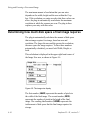
Accessing the Tone window
To access the tone window, click on the Tone window icon in
the plug-in Main window, illustrated in Figure 6-4:
Figure 6-4: The Tone window icon
Leaf scan 35 / 45, version 2.1
6-7
Toning a Digital Image
The Tone window appears, as in Figure 6-5:
Figure 6-5: The Tone window
Exiting the Tone window
You can exit from the tone curve by clicking on Cancel or OK.
6-8
•
OK - applies the current tone curve to the image and
returns you to the Main window.
•
Cancel - returns you to the Main window without applying
any of the changes.
Leaf scan 35 / 45, version 2.1
Modifying the tones in a range
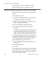
Reading a tone curve
The autorange process is represented by a graph of the tonal
values in an image. This graph is called a tone curve. When
the tonal values are unadjusted, the tone curve looks like the
one in Figure 6-6:
Figure 6-6: An unadjusted tone curve
The horizontal axis represents the tonal values of the original
image. The vertical axis represents the tonal values of the
output image. The bottom left hand corner of the graph
represents the lightest point in the image. The top right hand
corner represents the darkest point in the image. The line
between the endpoints represents all the tones between the
lightest and the darkest points. This line also represents how
an input value (horizontal axis) maps to its corresponding
output value (vertical axis).
The unadjusted tone curve of both color and grayscale images
looks like a straight line, as shown in Figure 6-6. When you
Leaf scan 35 / 45, version 2.1
6-9
Toning a Digital Image
adjust the shades of a grayscale image, the resulting tone
curve may look something like the one in Figure 6-7.
Figure 6-7: An adjusted tone curve of grayscale image
When you adjust the shades of a color image, the resulting
tone curve may look something like the ones in Figure 6-8.
Figure 6-8: An adjusted tone curve of a color image
The lines in the color tone curve are color-coded to represent
the red, green, and blue components of the image. The black
tone curve represents the average of the three components.
All these lines represent the highlights, midtones and
shadows of each set of tones that the image comprises.
6-10
Leaf scan 35 / 45, version 2.1
Modifying the tones in a range
Modifying a tone curve
You can change the tonal quality of an image by -modifying
tone curves. You modify a tone curve in one of three ways:
•
by clicking on and dragging a handle on the tone curve
A handle is a white circle on the line. It turns into a black
square when you click on it, indicating that it is active.
•
by pressing the arrow keys to move the selected handle
one step in the direction of the selected arrow key
•
by entering the position of an active handle numerically
Clicking and dragging a handle
To move a tone curve by clicking and dragging:
1. Click on a handle with the mouse button.
The handle changes from a circle to a black square to
indicate that it is active.
2. Drag the handle to a new position on the graph.
After you release the handle, the image in the display area
changes to reflect the modification you made to the tone
curve.
The handle remains active until you select another handle.
Entering a position numerically
The position of the active handle is numerically recorded in
the Active Handle Position boxes. You can also enter the
position of an active handle in the Active Handle Position
boxes shown in Figure 6-9.
Leafscan 35 / 45, version 2.1
6-11
Toning a Digital Image
Figure 6-9: Active Handle Position boxes
The position box labeled In represents the horizontal position
of the enabled handle. The position box labeled Out
represents the vertical position of the enabled handle.
To enter the position of a tone curve handle numerically:
1. Click on a handle to enable it.
The handle changes from a hollow circle to a black square.
2. Enter an integer between I and 100 in one of the position
boxes.
3. Press the TAB key.
The active handle moves to the position you entered
numerically.
If the values you enter are not within the range of the tonal
values, the software selects to the closest values that are
within the range.
6-12
Leafscan 35 / 45, version 2.1
Modifying the tones in a range
Modifying the tone curves of a color image
Unlike grayscale images, which have one tone curve, color
images have one tone curve for each color component and one
tone curve that represents the average of the color
components. You can select and modify any of these tone
curves.
Displaying and modifying the average of all color components
Click on Average.
The tone curve representing the average of all color
components appears on the screen. You can modify the tone
curve by clicking and dragging on a curve handle.
Displaying and modifying an individual color component
Click on the color component you want to change:
• Red
• Green
• Blue
The tone curve of the color component you clicked on appears
on the screen. You can modify the tone curve by clicking and
dragging on a curve handle.
Displaying and modifying all color component at once
Click on All.
All the tone curves appear on the screen. You can modify all
the tone curves in unison by clicking and dragging a curve
handle on the black line.
This option lets you see the effect on all the curves.
Leafscan 35 / 45, version 2.1
6-13
Toning a Digital Image
Modifying the brightness of an image
Brightness is a measure of how light or dark an image is.
Think of the brightness setting on a television set. If you turn
down the brightness, the entire image becomes darker. If you
turn up the brightness, the entire image becomes lighter.
You control the brightness of an image with the Brightness
slider shown in Figure 6-10:
Figure 6-10: The Brightness slider
The number on the right over the slider indicates the
intensity of brightness. The number ranges from I to 100.
You can use the Brightness slider by clicking or dragging:
•
Click the mouse on one of the arrows at either end of the
slider. The brightness increases or decreases by a measure
of 1.
•
Press and hold the cursor on the square in the middle of
the slider, then drag the square to the position you want.
When you click or drag to the right, the image becomes
lighter. When you click or drag to the left, the image becomes
darker.
Modifying the contrast of an image
Contrast is a measure of the relationship of light and dark
areas in an image. If you increase contrast, the light parts
become lighter and the dark parts become darker. When you
decrease contrast, the light parts become darker and the dark
6-14
Leafscan 35 / 45, version 2.1
Using tone curve utilities
parts become lighter. The number on the right over the slider
indicates the intensity of contrast. The number ranges from I
to 100.
You control the contrast of an image with the Contrast slider
shown in Figure 6-11:
Figure 6-11: The Contrast slider
You can use the contrast slider by clicking or sliding:
•
Click the mouse button on one of the arrows at either end
of the slider. The contrast increases or decreases by a
measure of 1.
•
Press and hold the mouse cursor on the square in the
middle of the slider, then drag the square to the position
you want.
When you click or slide to the right, contrast of the image
increases. When you click or slide to the left, the contrast of
the image decreases.
Using tone curve utilities
Tone curve utilities are designed to facilitate your workflow
and reduce redundancy in the work process.
Saving a tone curve
You can save a tone curve independently of an image and
later apply the curve to another image. You can save the curve
with or without the endpoints.
Leafscan 35 / 45, version 2.1
6-15
Toning a Digital Image
To save a tone curve:
1. Click on Save.
The following window appears:
2. Select a location for the tone curve from the list.
3. Enter a name for the tone curve you are saving.
4. Click OK.
Loading a tone curve
You can load a tone curve that you saved and apply it to the
prescanned image in the display area. This feature is useful
when you are scanning from a roll of film where all the frames
share a common exposure -as in a motor driven sequence. In
such a case, all the film images may be similarly exposed and
may require the same tonal treatment to get the results you
want.
To reload and apply a tone curve, click on Load. The window
in Figure 6-12 appears:
6-16
Leaf scan 35 / 45, version 2.1
Using tone curve utilities
Figure 6-12: Load window
In the dialog box, do the following:
1. Click on a tone curve from the list to select it.
The tone curve becomes highlighted.
2. Check Load black and white points, if you want.
3. Click OK to apply the tone curve to the image in the
display area.
The tone curve you selected appears in the Tone window.
Applying a tone curve
Click on Apply to give the tonal values in the tone curve to the
image in the display area. When you click on Final Scan, the
image is produced with the tone curve that you apply. When
you Apply a tone curve, you remain in the Tone window.
You also Apply a tone curve when you click on OK. In this
case, you return to the Main window.
Leafscan,35 / 45, version 2.1
6-17
Toning a Digital Image
Resetting a tone curve
Resetting a tone curve straightens the current tone curve.
To reset a tone curve, click on Reset in the Toning window.
Using the Densitometer
This section describes the plug-in densitometer display.
What is a densitometer?
In traditional photography, a densitometer is a device that
measures density of inks and emulsions and reports the
density in numeric values. Density represents the degree of
darkness in an area.
A digital densitometer is a software tool that measures and
displays the values of pixel components in terms of capture
and final values. You may elect to convert the pixel values into
a more traditional densitometer reading (for example,
between 0.0 and 4.0). Using a densitometer is more reliable
than gauging by eye whether a tone that is displayed on the
monitor has a specific value.
When you place the mouse cursor in the image display area,
the cursor acts as a densitometer and displays readings in the
area to the right of the tool palette.
The basic steps to using the digital densitometer are:
1. Setting the densitometer to read and display values the
way you want.
2. Using the densitometer to get readings.
6-18
Leafscan 35 / 45, version 2.1
Using the Densitometer
Setting the densitometer
You can set the densitometer to:
•
read the values of either a single pixel or the average of a
3 x 3 patch of pixels
•
display readings in terms of pixels or density value
To set the densitometer:
1. Select More Settings Û Densitometer. The following
window appears:
2. Under Sample Method, select how you want the
densitometer to read values by clicking on one of the
following:
•
Single Point - displays reading of the single pixel the
cursor is on
•
Average Neighbors - displays the average of a 3x3
patch of pixels
3. Under Display, select how you want the readings to be
displayed in the Densitometer Display area by clicking on:
Leafscan 35 / 45, version 2.1
6-19
Toning a Digital Image
•
Pixel Value - displays the reading in terms of capture
values
This reading is independent of any toning you have
applied to the image. The default minimum is 0 and
the default maximum is 65535.
•
Density - displays readings in terms of traditional
density values. Recommended entries are 0 for
minimum and 4.0 for maximum.
•
Output Pixel Values - displays final values (8 bit RGB
values similar to those measured in Photoshop after
you create a final image). This reading is calculated
from the image you see displayed. Density readings
include the effects of any toning you have applied.The
default minimum is 0 and the default maximum is 255.
4. Under Display, enter the range within which the readings
are displayed:
•
•
Minimum - the lower end of the range
Maximum - the upper end of the range
5. Click OK.
When you move the cursor inside the image display area, the
display you have selected appears on the right of the tool
palette.
Understanding densitometer readings
This section shows examples of ways that you can display
digital densitometer values. To see the densitometer readings,
look at the far right of the Tool Palette.
6-20
Leaf scan 35 / 45, version 2.1
Using the Densitometer
Densitometer set to display density
Figure 6-13 shows densitometer values in terms of density:
R/C: 0.03
G/M: 0.03
B/Y: 0.03
Figure 6-13: The densitometer set to display in terms of density
The numbers represent the density reading for the pixel or
patch of pixels under the cursor.
Densitometer set to display output values
Figure 6-14 shows densitometer values in terms of output
values, or final values:
R/C:
33.55 G/M:
33.55 B/Y:
33.55
Figure 6-14: The densitometer set to display in terms of output values
The numbers represent the final value reading for the pixel or
patch of pixels under the cursor.
Densitometer set to display pixel values
Figure 6-15 shows a densitometer display when the image is
in color and the densitometer is set to display values in pixels.
RED: 1414 GREEN: 2103
BLUE: 2244
Figure 6-15: The densitometer set to display in pixels
Leaf scan 35 / 45, version 2.1
6-21
Toning a Digital Image
Densitometer set to display values in a grayscale image
Figure 6-16 shows a densitometer display when the image is
grayscale and the densitometer is set to display values in
pixels.
GRAY:
2176
Figure 6-16: The densitometer set to display in pixels for grayscale image
Updating densitometer readings when toning
When the tone window is open, and you make an adjustment
to toning, you must click on Apply to update the densitometer
reading.
General guidelines for toning images
How you tone an image depends on the effect you want to
achieve. However, the following is a recommended order of
using the toning tools:
1. Select the endpoints by using the following tools in the
following order:
•
Autorange tool - If the first autorange does not produce
the effect you want in the image, move the autorange
box to another part of the image.
•
White Point and Black Point tools - You can do an
autorange and then use both/either the White point or
the Black Point tool to fine-tune the tonal range.
2. After you select the endpoints of a range, use the following
tools to further modify the tones:
•
6-22
Tone curve
Leafscan 35 / 45, version 2.1
General guidelines for toning images
•
•
Contrast slider
Brightness slider
The order in which you use the toning tools is not as
important as the aspect of the image you are trying to
modify.
Leafscan 35 / 45, version 2.1
6-23
7
Creating a Final Image
This chapter describes how to create a final image and some
additional steps that let you control image storage and
acquisition.
Creating a final image
To create a final image, click on Final Scan.
This single step is the culmination of the modifications you
have made to the prescanned image.
Leafscan35 / 45,version2.1
7-1
Creating a Final Image
Before you remove the film holder. . .
After you scan, but before you remove the film holder, click on
Eject in the Main window to prevent damage to the scanner.
The Eject button centers the film holder in the scanner
opening. This feature is important because the scanner works
by moving the film holder back and forth. When the scanner
finishes scanning, it may leave the film holder in a position
that may prevent you from pulling it out of the scanner.
Eject works differently on the Leafscan-35 and on the
Leafscan-45. On the Leafscan-35, the Eject button centers the
film holder, making it ready for you to pull it out of the
scanner. On the Leafscan-45, the Eject button centers and
moves the film holder out of the scanner.
Reloading a saved prescanned image
After you click on Final Scan, the software automatically
saves the prescanned image under the filename Leafscan
Image File in the same directory in which you installed the
plug-in.
To retrieve and display the prescanned image, click on Reload
in the Main window.
Reload retrieves the prescanned image and all the
information associated with it when you clicked on Final
Scan. This information includes:
7-2
•
position of Crop box
•
width and height values
•
resolution
•
type of film format
Leafscan 35 / 45, version 2.1
Troubleshooting
•
•
toning information
position of focus line (Leafscan-45 only)
Troubleshooting
If you are having problems with the software or the scanner,
please call your Leaf Systems representative. The service
representative may ask you to look at the Scanner
Information window. This window contains diagnostic
information that a customer service representative needs to
help you solve problems with the software or the scanner.
To access the Scanner Information window, select More
Settings Û Scanner Info. The Scanner Information window
appears, as in Figure 7-1:
Figure 7-1: Scanner Information window
Leafscan 35 / 45, version 2.1
7-3
Creating a Final Image
Error messages
Figure 7-2 lists some error messages that you may see when
you are capturing prescanned and final images
Error Message:
What To Do:
Can't save prescan image this time.
Remove files from the disk and capture another
prescanned image. The disk is full or the Leafscan
image file is locked or corrupted.
Can't load the prescan image from
"Leafscan Image File".
Capture new prescan. The Leafscan image file is
missing or corrupted.
There is not enough memory available to
open Leafscan now. Please close some
windows and try again.
• Save and close some of the pictures on the
monitor.
• Highlight the Photoshop icon, then select Get
Info from the Finder. A minimum of 5120k
must be allocated to the application.
Scanner problems detected. Please see
"Scanner Info..." for more details.
Select Scanner Info from the More Settings menu
to view additional error messages. Check this table
for information about what to do.
Camera: Not enough light at CCD for
calibration. Or, below legal limit.
• Remove lens cap and film holder from
scanner.
• Open the lens by setting a lower number (f/4 is
wide open). Leafscan-45 only.
• Clean colored filters (air).
• Perform lamp controller adjustment. Leafscan
45 only.
• Replace the bulb, then perform lamp
controller adjustment
Figure 7-2: Leafscan 35/45 error messages
7-4
Leafscan 35 / 45, version 2.1
Error messages
Error Message:
What To Do:
Camera: Subrange gain out of range.
• Clean colored filters (air).
• Perform lamp controller adjustment. Leafscan
45 only.
Camera: Too much light at CCD for
calibration.
• Close the lens by setting a higher number
(not more than f/8). Leafscan 45 only.
• Perform lamp controller adjustment.
(Leafscan 45 only.)
DSP: Pixel value overflow during scan.
Ignore this message unless artifacts appear in the
scan.
Lamp: Controller fault or bad lamp. LS 45
only
• Remove lens cap and film holder from
scanner.
• Clean colored filters (air).
• Perform lamp controller adjustment. Leafscan
45 only.
• Replace the bulb, and then perform lamp
controller adjustment. Leafscan 45 only.
Please move the green focus line to a
different area. Leafscan 45 only.
Move the focus line only if image is blurry (that is,
fuzzy or "under water").
Figure 7-2: Leafscan 35/45 error messages
Leafscan 35 / 45, version 2.1
7-5
Creating a Final Image
Leafscan-45 quick reference
This section is a quick reference about how to capture a final
image with the Leafscan-45.
Leafscan-45: Once per session
1. Acquire LS 35/45 Plug-In.
2. Select format of film.
3. Calibrate the scanner.
4. (Optional) Set Exposure.
5. (Optional) Focus.
Leafscan-45: Once per image
1. Select type of output image.
2. Capture a prescanned image.
3. (Optional) Crop and size image.
4. (Recommended) Create a prescanned image of the cropped
area.
5. (Optional) Focus.
6. (Optional) Tone prescanned image
7. Capture a final image.
7-6
Leafscan 35 / 45, version 2.1
Leafscan-35 quick reference
Leafscan-35 quick reference
This section is a quick reference about how to capture a final
image with the Leafscan-35.
Leafscan-35: Once per session
1. Acquire LS 35/45 Plug-In.
2. Calibrate the scanner.
3. (Optional) Set Exposure.
Leafscan-35: Once per image
1. Select type of output image.
2. Capture a prescanned image.
3. (Optional) Crop and size image.
4. (Recommended) Create a prescanned image of the cropped
area.
5. (Optional) Tone prescanned image
6. Capture a final image.
Leafscan 35 / 45, version 2.1
7-7
Index
Numerics
16 bit 4-17
24-bit color 2-2
A
accessing plug-in 1-2
active handle 6-11
Active Handle Position boxes 6-11
analog 2-3
application memory 3-3
autorange 6-22
7assigning endpoints 6-3
default position of box 6-2
definition 5-4
endpoints 6-2
how it works 5-4
selecting area 6-2
using tool 6-4
autorange selection window 6-3
autoranging 5-4
average neighbors 6-19
B
Black Point tool 6-6
Leafscan 35 / 45, version 2.1
brightness 6-14
bulb drift 2-4
C
calibrating the scanner 2-4
calibration
cancelling 2-6
definition 2-4
focus 2-5
how to 2-4
Leafscan-35 2-5
prescan 2-5
when necessary 2-4
capture and final values 5-5
capture values 3-2, 5-2, 5-3
definition 5-8
color components 6-13
columns
as height 4-9
as width 4-8
Concept 5-5
contrast 6-14
conventions iii
conventions, manual iii
Crop box 4-2,4-3
Index-1
locating 4-3
moving 4-3
one-dimension lock 4-11
sizing 4-3
unlocked 4-11
cropping 4-2,4-15
current, exposure 2-8
custom exposure 2-9
D
definition
capture values 5-8
export values 5-8
densitometer 6-18
definition 6-18
digital 6-18
display 6-19
how to read 6-20
min and max values 6-20
sample method 6-19
traditional 6-18
updating readings 6-22
density 6-20
display area, sizing 3-3
dpi 4-13
dynamic range 2-9
eject 7-2
emulsion, damaged 6-2
endpoint settings 6-4
endpoint values, assigning 6-3
endpoints
Index-2
automatic selection of 6-2
defined 6-2
overview 6-2
selecting 6-2,6-22
endpoints, selecting 6-1
endpoints
selecting with box 6-2
error messages 7-4
exiting plug-in 1 -5
export values
definition 5-8
exposure
adjusting 2-6
current 2-8
current setting 2-8
filter identifier 2-7
reading slider 2-7
setting indicator 2-8
using minimum 2-9
using optimum 2-9
window 2-6
exposure range 2-8
exposure settings on sliders 2-8
exposure sliders, reading 2-7
exposure time window 2-6
exposure, optimum 2-8
F
film format 2-3,7-2
maximum settings 2-3
menu 2-3
film holder 7-2
film recorders 4-16
film size, selecting 2-3
Leaf scan 35 / 45, version 2.1
film, dirty 6-2
filter identifier 2-7
final image 4-15,7-1
Final Image Type menu 3-3
final image types 3-4
final image, and memory 4-14
final scan 7-1
final values 5-3
focus
how to after prescan 4-18
when to 4-17
focus line 7-3
focusing 3-4,4-17
before prescan 3-4
G
GPIB 1-2
H
halftone screen 4-15
height 4-1,7-2
I
image area 4-3
image proportion 4-3
image quality and size 4-15
image size area 4-5
image size display 4-14
image size in pixels 4-16
installing plug-in 1 -2
L
Leafscan Image File 7-2
Leafscan-35 quick reference 7-7
Leafscan-45 only
film format 2-3
focusing 3-4
Leafscan-45 quick reference 7-6
locked 4-6
locking dimensions 4-6
M
magnification 2-3
Main window 1 -3
maximum 6-20
Maximum Range 6-4
maximum settings
specifications 2-4
maximum settings, film format 2-3
minimum 6-20
modifying tonal range 6-1
monitor 2-2
adjustment through hardware 2-2
adjustment through software 2-2
and final values 5-4
color representation 2-2
evaluating images 2-2
limitations 2-2
size 3-3
N
neutral
definition 5-7
neutral pixel 5-7
Leafscan 35 / 45, version 2.1
Index-3
O
optimum, exposure 2-8
output pixel values 6-20
overview
autorange 5-4
digital images and size 4-1
endpoints 6-2
Main window 1-3
product 1-1
toning 5-2,6-1
Toning window 1 -4
workflow 1-2
P
percentage as width 4-9
pixel 5-6
component 5-6
neutral 5-7
representing color 5-6
representing shades 5-7
value of color component 5-7
value of grayscale component 5-7
pixel value 6-20
post-production correction 5-3
prescan, preparing to 3-1
prescanned image
and autorange 3-2
and capture values 3-2
defined 3-2
purpose 3-2
summary 3-5
setting up 3-3
printer 4-13
Procedure
Index-4
loading tone curves 6-16
procedure
accessing plug-in 1 -2
accessing Tone window 6-7
applying tone curve 6-17
autoranging 6-4
calibrating the scanner 2-4
cancelling calibration 2-6
creating final image 7-1
cropping 4-3
entering resolution 4-13
exiting 1-5
exiting tone window 6-8
focusing 3-4
installing 1-2
isolating cropped area 4-4
modifying brightness 6-14
modifying contrast 6-14
modifying tone curve 6-11
prescanning cropped area 4-4
reloading prescanned image 7-2
resetting tone curve 6-18
saving tone curves 6-15
selecting film format 2-3
setting densitometer 6-19
setting exposure 2-10
setting image size for halftone
screens 4-15
setting image size in pixels 4-16
setting maximum exposure 2-9
setting minimum exposure 2-9
setting width and height 4-5
sizing display area 3-3
using Black Point tool 6-5
updating densitometer readings
6-22
Leaf scan 35 / 45, version 2.1
using columns 4-7
using Custom exposure 2-9
using densitometer 6-19
using percentage 4-9
using white point tool 6-5
proportions and locks 4-10
R
resolution 4-1,4-11,7-2
16 bit 4-17
and monitor 4-13
and printer 4-13
and scanner 4-13
definition 4-12
detail and contrast 4-13
effect on image 4-12
entering 4-13
how displayed 4-13
output device 4-15
softness 3-5
S
sample method 6-19
scanner info 7-3
SCSI 1-2
session, preparing for 2-1
Set Black Only 6-4
Set Both 6-4
Set White Only 6-4
setting indicator, exposure 2-8
Single Point 6-19
specular highlights 6-2
Leaf scan 35 / 45, version 2.1
T
tonal range, modifying 6-1, 6-7
tone curve
how to read 6-9
adjusted 6-10
all 6-13
average 6-13
color image 6-10
darkest point 6-9
horizontal axis 6-9
individual color components 6-13
lightest point 6-9
modifying 6-11
numeric position 6-11
unadjusted 6-9
vertical axis 6-9
tone curve utilities 6-15
toning
and prescanned image 5-2
definition 5-2
general guidelines 6-22
overview 5-2,6-1
toning concepts 5-1
toning information 7-3
Tone window 1 -4
accessing 6-7
exiting 6-8
trouble shooting 7-3
U
unlocked 4-6
Index-5
Leafscan 35/45 Plug-In, Version 2.1
Part Number: 99422
Leaf Systems, Inc.
250 Turnpike Road
Southborough, MA01772
(508) 460-8300