1
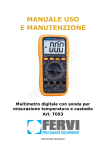
20A
DIGITAL MULTIMETER
1-7.Operation: 0~40℃,relative humidity <80%
OPERATION MANUAL
1-9.Power:one 9V battery (NEDA1604/6F22 or equivalent)
Overload protection: 0.2A / 250V restorable fuse, range 20A infused.
2-3-4. ACA
1-11.Weight: approx.448g (including a battery)
1. GENERAL
2) TECHNICAL DATA
The instrument is a stable and good performance digital multimeter driven by
2-1.Accuracy: ±(a% × reading + dgts ) at (23 ± 5)℃, relative humidity<75%.
One year guarantee since production date.
2-2. Function:
is convenient.
·DCV
·Resistance Ω
·Temperature ℃ & ℉
The instrument has the function of measuring DCV, ACV, DCA, ACA, resistance,
·ACV
·Diode continuity testing
·Frequency
f
capacitance, inductance, temperature and frequency, and diode, triode and
·DCA
·Triode
·Inductance
L
continuity test. The instrument takes dual-integral A/D converter as key point, is an
·ACA
·Capacitance C
hFE
·Auto power-off
· Backlight
2-3. TECHNICAL DATA
2. SAFETY NOTES
2-3-1. DC Voltage
This series meter meets the standard of IEC1010. Please read below notes
Range
Accuracy
Resolution
carefully before operation.
200mV
2V
20V
200V
1000V
±(0.5%+3)
100uV
1mV
10mV
100mV
1V
1.Do not input a limited voltage which RMS is over DC 1000V or AC 700V when
measuring voltage.
2.Voltage less than 36V is a safety voltage. When measuring voltage higher than
DC 36V, AC 25V, check the connection and insulation of test leads to avoid electric
shock.
5.When measuring current, do not input current over 20A.
6.Safety symbols
“
” exists high voltage , “
refer to manual,“
±(0.8%+10)
” GND , “
” dual insulation , “
” low battery
” must
±(1.2%+5)
Resolution
100uV
1mV
10mV
100mV
1V
Other ranges: DC 1000V or AC peak value
Frequency response:Range less than 200V: 40~400Hz
1-1.Displaying : LCD displaying
Range 750V: 40~100Hz
1-2.Max. indication: 1999(3 1/2), auto polarity indication
Displaying: RMS of sine wave (mean value response)
1-3.Measuring method: dual slope A/D transfer
2-3-3. DCA
1-5.Over range indication: MSD displays “1” / “OL” or “-1” / “-OL”
1-6.Low battery indication: “
” symbol displays
Frequency response:40~200Hz
Displaying: RMS of sine wave (mean value response)
2-3-5. Resistance(Ω)
Range
200Ω
2kΩ
20kΩ
200kΩ
2MΩ
20MΩ
Accuracy
± (0.8%+5)
± (0.8%+3)
± (1.0%+15)
Range
2mA
20mA
200mA
Resolution
0.1Ω
1Ω
10Ω
100Ω
1kΩ
10kΩ
Open voltage:less than 3V
Overload protection:DC 250V or AC peak value
A : At range 200 Ω, short-circuit the test leads to measure the wire
B:At range 200 MΩ, when the test leads short circuit, LCD displays 1.0 MΩ. In the
same way, the reading is 10 MΩ while the test leads short at range 2000 MΩ.
Accuracy
±(0.8%+5)
±(0.8%+5)
Input impedance:It is 1MΩ at range 200mV or 2V, and be 10MΩ at others;
3. SPECIFICATION
1-4.Sampling rate: approx. 3 times/sec
Overload protection: 0.2A / 250V restorable fused, Range 20A infused.
resistance, then, subtracts it from the real measurement.
Other ranges: DC 1000V or AC peak value
Range
200mV
2V
20V
200V
750V
Resolution
1uA
10uA
100uA
10mA
Max. input current: 20A (within 10 second)
Overload protection:Range 200mV: DC 250V or AC peak value
Overload protection: Range 200mV: DC 250V or AC peak value
1) GENERAL
±(2.0%+5)
±(3.0%+10)
NOTE:
2-3-2. AC Voltage
4.Select correct function and range to avoid fault operation.
Accuracy
±(1.0%+15)
Input resistance:The Max. input impedance:10MΩ
3.Be sure to keep the test leads off the testing point when converting function and
range.
Range
2mA
20mA
200mA
20A
Max. measuring voltage drop: 200mV
symbol displaying, backlight and the function of overload protection make operation
excellent tool.
10mA
Max. input current: 20A (within 10 seconds)
1-10.Size: 190×93.5×37mm
battery. It uses the LCD with 42mm-high figure to make the reading clear. Unit
±(2.0%+5)
Max. measuring voltage drop: 200mV;
1-8.Storage: -10~50℃,relative humidity <80%
It’s normal and doesn’t affect the accuracy. Please deduct the value from the
real measurement.
C : The reading be displayed slowly when the measurement is more than 1 MΩ.
Please wait it to be stable.
2-3-6. Capacitance
Range
20nF
200nF
2uF
20uF
200uF
Accuracy
±(2.5%+20)
±(5.0%+10)
Resolution
10pF
100pF
1nF
10nF
100nF
Overload protection:DC 36V or AC peak value
2-3-7. Inductance (L)
Accuracy
±(0.8%+10)
±(1.2%+8)
Resolution
1uA
10uA
100uA
Range
2mH
20mH
Accuracy
Resolution
±( 2.5%+30)
1uH
10uH
200mH
2H
20H
100uH
1mH
10mH
and range.
2. Set the knob to a proper resistance range, and connect the leads crossly with the
4. Voltage, resistance and frequency COM
resistor under tested.
5. GND
NOTE:
6. COM for measuring current less than 200mA
1. The LCD displays 1 or OL while the resistance is over the selected range. The
7. COM for measuring current 20A
knob should be adjusted to a higher range.
SEE THE FIG.
2. When input terminal is in open circuit, overload displays.
4-2.Voltage measurement
3. When measuring in line resistor, be sure that the power is off and all capacitors
1. Apply the black test lead to “COM” terminal and the red one to V/Ω/Hz terminal.
are released completely.
2. Setup the Knob on a proper range “V”. If the voltage range is unsure beforehand,
4. Do not input any volt at resistance range.
please set it on the max., then measure diminishingly to reach a resolute value.
5. When measuring value is over 1MΩ, the reading will take a few seconds to be
3. Press the DC/AC key down to AC mode to measure AC voltage. Oppositely,
stable. It’s normal for high resistance measuring.
resile the key to DC mode to measure DC voltage.
4-5.CAPACITANCE MEASUREMENT
4. Connecting the test leads reliably with the tested circuit, the voltage value will be
Apply the knob to proper capacitance range, and insert the capacitor under tested
displayed on LCD. While testing a DC voltage, the reading is voltage and polarity of
into “mA” and “COM” terminal, be wary of polarity if necessary.
the point connected by the red lead.
NOTE:
NOTE:
1. If the capacitance under tested is over the max. value of selected range, LCD
1. While the reading is 1 or OL,the voltage is beyond the present range. Now you
displays 1 or OL, thus, should set the knob to a higher range.
need to set the knob to the higher.
2. It’s normal that there is a remained value on LCD before capacitance
2. Do not input a voltage over DC 1000V or AC 750V. Please keep the test leads off
measurement, and it doesn’t affect the measurement.
the circuit while switching the function or range
3. When measuring at large capacitance range, if capacitor is crept badly or broken,
3. Be carefully while measuring a high voltage. DO NOT touch the circuit.
LCD displays a value and it’s unstable.
Overload protection:DC 250V or AC peak value
4-3.Current measurement
4. Release the capacitor completely before measuring.
CAUTION:DO NOT INPUT VOLTAGE AT THIS RANGE!
1. Apply the black test lead to “COM” terminal and the red one to “mA” or “20A”
4-6.INDUCTANCE MEASUREMENT
2-3-11. Transistor hFE DATA TEST
terminal.
Set the knob to a proper inductance range and insert the inductor to “mA” and
2. Set the knob to a proper range A. If the current under tested is unsure
“COM” terminal.
beforehand, please set it on the max., then measure diminishingly to reach a
NOTE:
resolute value.
1. The LCD displays 1 or OL while the tested inductance is over the selected range.
4. OPERATION
3. Press the DC/AC key down to AC mode to measure AC current. Oppositely,
Thus, the knob should be set to a higher range.
4-1.Panel description
resiling the key to DC mode to measure DC current.
2. The inductance may be different due to different resistance on a same inductor.
1. LCD: display the measuring value and unit.
4. Connecting the leads with the tested circuit in series, the current value is
3. At 2mH range, should make the test leads short and measure the inductance of
2. Function key
displayed on LCD. While testing a DC current, the reading is the value of current
wire, then, subtract from real measurement.
2-1. POWER switch: turn on/off the power.
and polarity of the point connected by the red lead.
4-7.TEMPERATURE MEASUREMENT
2-2. Backlight key
NOTE:
Set the knob to ℃ range, insert the black plug of cold end of thermocouple into mA
2-3. Transistor test jack
1.If the LCD displays 1 or OL,it means the current is over range. Now you need
com and the red plug to “COM” com , put working end into measurement place.
2-4. HOLD key: press it, the present value is held
to set the knob to the higher.
Display reading is the temperature of measurement place in ℃&℉.
on LCD and “ H ” symbol displays. Press it again,
2.Max. input current is 200mA or 20A (subject to where the red test lead apply
NOTE:
“ H ” symbol disappears, and the meter is exited
to), too large current will blow the fuse. Be sure the test is less than 10 seconds.
1. When input terminal is in open circuit, if the ambient temperature is over 18℃,
the holding mode.
Please keep the leads off the circuit while switching the function and range knob.
under 28℃ LCD displays the ambient temperature. If ambient temperature is lower
2-5. DC/AC key:set DC or AC working mode.
4-4.RESISTANCE MEASUREMENT
than 18℃and over 28℃, LCD displays just for the reference.
3. Range knob: to select measuring function
1. Apply the black lest lead to COM terminal and the red one to V/Ω/Hz terminal.
2. Do not try to change the thermocouple, or, the accuracy cannot be guaranteed.
Overload protection:DC 36V or AC peak value
2-3-8. Temperature
Range
(-20 ~ 1000)℃
Accuracy
Resolution
±(1.0%+5) < 400℃
1℃
±(1.5%+15) ≥ 400℃
±(0.75%+5)<750℉
(0 ~ 1832)℉
1℉
±(1.5%+15)≥750℉
K-type thermocouple ( banana shape plug )
2-3-9. Frequency
Range
200kHz
Accuracy
±(3.0%+18)
Resolution
100Hz
Input sensitivity:1V RMS
Overload protection:DC 250V or AC peak value (within 10 seconds)。
2-3-10. Diode and continuity testing
Range
Reading
Condition
Forward voltage drop of diode
Forward DCA is approx.
1mA, the backward
voltage is approx 3V
Open voltage is approx.
3V
Buzzer makes a long sound
while resistance is less than
70Ω±20Ω
hFE
Range
NPN or PNP
Displaying range
0 ~ 1000
Test condition
Basic current is approx. 10uA
, Vce is about 3V
3. Do not input any volt at a temperature range.
5-4. If do not operate for a long time, should take out the battery to avoid leakage
4-8. FREQUENCY MEASUREMENT
Note: When
signal displays, should replace the battery following the steps
1. Apply test leads or shield cable to COM and V/Ω/Hz terminal.
2. Set the knob to frequency range, connect test leads or cable crossly to signal
6. If the meter does not work properly, check the meter as following:
Fault
source or tested load.
No reading on LCD
NOTE:
Solution
●Power off--- Pls turn on the power
●Holding key---PLs set a correct mode
1. When input over 10V RMS, reading is workable but accuracy is not guaranteed.
2. It is better to use shield cable to measure small signal at noisy environment.
3. Be careful when measuring high volt circuit.
4. Do not input voltage over DC 250V or AC peak value.
●Replace battery
The signal
appears
No current or temperature input
Error Value
●Replace battery
●Replace fuse
●Replace battery
5. Auto range test from 2kHz to 10MHz.
4-9. TRANSISTOR hFE
1. Set the knob to hFE range.
2. insert the Test accessories to “mA” and “COM” terminal.
3. Verify the transistor under tested is NPN or PNP, insert emitter, base and
●The specifications are subject to change without notice.
●The content of this manual is regarded as correct, error or
omits Pls. contact with factory.
●We hereby will not be responsible for the accident and damage
collector to proper jack.
caused by improper operation.
4-10. DIODE AND CONTINUITY TEST
1. Apply the black test lead to “COM” terminal and the red one to V/Ω/Hz terminal
●The function stated for this User Manual cannot be the reason
of special usage.
the polarity of red lead is “+”).
2. Set the knob to
range, connect test leads to the diode under tested, the
red test connect to diode positive polarity, the reading is the approx. value of diode
forward volt drop.
3. Apply test leads to two points of tested circuit, if the inner buzzer sounds, the
resistance is less than (70 ± 20) Ω.
4-11.DATA HOLD
Press down the key, the present value is held on LCD. Press up the key and the
function is cancelled.
4-12.AUTO POWER OFF
After stop working for 20±10 minutes, the meter will be into sleep mode. Press
“POWER” key twice to restart the power.
4-13: Backlight
Press the “B/L” key to turn on the backlight,will be auto off after 10 sec.
5.MAINTENANCE
Do not try to modify the electric circuit.
5-1. Keep the meter away from water, dust and shock.
5-2. Do not store and operate the meter under the condition of high temperature,
high humidity, combustible, explosive and strong magnetic place.
5-3. Wipe the case with a damp cloth and detergent, do not use abrasives and
alcohol.
MB-9805-50