1
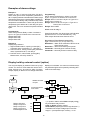
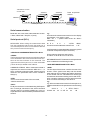
Examples of alarm settings:
Example 1.
Display 0..100.0 °C and one high alarm (HI) 60°C.
Alarm must get off when temperatur goes down to
58°C. Display has been ordered with two alarm relays
and with two changeover contacts (Relay card REL2).
HI level means closing relay indication lamp when
temperature exceeds 60°C. Alarm will get off when
temperature goes below 58°C and relay will open.
’Alarm-OFF’ turns out unused front panel indication
lights.
Programming:
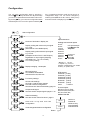
Slot C-Setup-Card4-Relay1-Alarm-Level 260Hyst1.0-Type AL Hi-Reset Auto-Contact Nc.
Relay2-Alarm-Level150.0-Hyst 0.5-Type-Al LoReset Auto-Contact no
Relay3-Alarm-Level120.0-Hyst1.0-Type-Al LoReset User-Contact nc
Relay4-Alarm-OFF
Alarm reset of relay 3:
Programming:
Slot C-Setup-Card2-Relay1-Alarm-Level 60.0Hyst -2.0-Type-Al Hi-Reset-Auto-Contact-No.
Relay2-Alarm-OFF
Relay3-Alarm-OFF
Relay4-Alarm-OFF
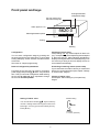
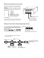
Press front panels ➤-key three times until indication
light A3 turns on. You can reset alarm by *-key.
Other relays will reset when alarm turns out.
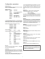
Description of Type-Reset-Contact-User
Type =selection low (Lo) or high alarm (Hi)
Reset-Auto = Alarm to be reset when value is not at
alarm level anymore
Reset-User = Alarm to be reset by front panel
Contact-No = Normally open contacts of relay
Contact-Nc = Normally closed contacts of relay
Example 2
Display range 0-600°C
1. High level alarm 260°C, opening contact (NC),
automatic reset. Hysteresis 1.0°, Use relay 1.
2. Low level 150°C, closing contact (NO), automatic
reset, Hysteresis 0.50°C, use relay 2
3. Low level 120°C, manual reset, opening (NC).
Manula reset, use relay number 3.
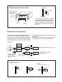
Display hold by external control (option)
display is in hold state. You can turn out the unnecessary indication lights on front panel by selecting OFFmode for unused relays.
You may lock display by external contact or by logic
control. You have to mount 2000-I/O card to slot C.
Other I/O-lines may be used for alarm functions.
Output, display or alarms do not change state when
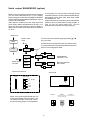
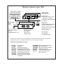
Main menu
Disable unused
I/O-port
Slot b
★
OFF
★
Slot C
Setup
Accept and exit to
main menu
★
Hold
Lo HoL
*)
HI HoL
Card 4
rELAy1
Alarm
A1
Relay1=I/O-port 1
Relay 2=I/O-port 2
Relay 3=I/O-port 3
Relay 4=I/O-port 4
Indicator lights A1..A4
A2
rELAy2
A3
rELAy3
A4
rELAy4
*) In position 'Alarm' select Hold to display with ▲key and select relay function:
Hold Lo Hol=0 (Closing contact)
Hold Hi Hol=1 (Opening contact or Logic function '1')
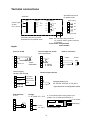
Card 2000-I/O accepts voltage input 5-32 VDC
stage='1' (corresponds open contact), '0'<1V.
10