1
Alarm functions
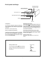
Alarm settings by front panel keys
Relay indication lights A1...A4
General description
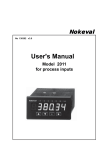
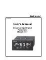
Panelmeter 2021 is provided with unexceptionally
many versatile alarm functions and therefore it has
plenty of basic selections. When basic selections
are done in config state, normal use with front
panel keys is very simple.
5620.0
*
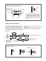
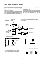
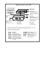
Alarm cards:
REL 2 =
two relays with changeover contacts
(grey connectors). You may use
two cards (4 relays). Second card is
mounted slot B.
REL 3 =
three relays with closing contacts. Only
one card for slot C. Grey connectors.
2000-I/O =
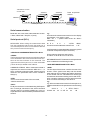
Checking of alarm value
Pressing ➤ once shows setpoint of alarm one (A1),
correspondingly second pressing shows setpoint of
alarm two (A2) etc. Alarm indication light blinks in
display informing that alarm level is displayed (if you
do not touch keys during 8 seconds the display
returns to normal state automatically).
Preventing of entering alarms (secret code)
If you have set secret code for alarms you must feed
it before you can change alarms (see chapter ”settings of secret codes” Page 14).
four I/O ports (logic alarm, green
connector). Only one card in slot C.
Grey connectors are used for power 230 VAC, 2A and
green connectors for 36 VDC, 100 mA.
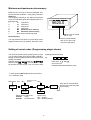
Changeing alarm value
First pressing of ➤ key shows setpoint of alarm one
(A1), second pressing shows setpoint of alarm two
etc. When indication light (A1..A4) blinks you can
change alarm level by pressing ▲ or ▼-key. You can
change setpoint of relay in question with keys ▲,▼,
➤. Accept change by ★-key (if you do not touch keys
during 8 seconds display returns to normal state with
automatically and save with same made changes).
Alarm type, hysteresis, etc. must be
done in configuration state.
Removing electronics from
case:
Press meter gently behind front
plate and draw front frame
forwards at upper edge.
Alarm mode, hysteresis and other settings are done
in configuration state.
Slot B Slot C
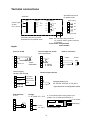
Alarm card connections
Input card
Indicators A1-A4
in front panel
6
5
4
3
2
1
Slot A
Slot B
6
Nc 5
No 4
3
Nc 2
No 1
Slot C
2000-I/O
Relay card REL3
Relay card REL2
6
5
4
3
2
1
4 logic outputs
or inputs
A1
Max.
230 VAC,
2A
A2
7 8 9
Optional cards are named as Slot C or B
8
6
5
4
3
2
1
A1
A2
A3
Max. 230 VAC,
2A
6
5
4
3
2
1
Max. 36 V,
100 mA
A1
A2
A3
A4
Com