1
Configuration parameters
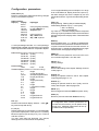
In mV-ranges Hi-setting acts as multiplier, f.ex. range
is 25 mV and Hi=3,50, display shows 87,5 (25 x 3,5).
Lo value changes zero level ± setpoint by mV and
temperature sensors. Typical use is eliminating sensor
error.
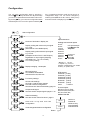
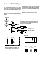
Undo, Save (➤)
Exit from configuration state without saving changes
(Undo) or save and exit (Save).
Input selection
Input (➤)
Display
25 mV
55 mV
100 mV
1000 mV
2500 mV
5000 mV
4-20 mA
0-20 mA
0-10 V
IR-140
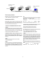
Filter (➤)
Display filtering. Filtering damps restless display.
Value setting between 1(min) ...0.010 (max).
1.000 = no filtering
0.200 = normal filtering
e.g. Filter = 0.2. The filtered display value is composed
summing 1/5 (20%) the latest measurement result and
4/5 (80%) the previous display value. Filter works liked
RC-filter
Input type
mV-input gives possibility
to select Bipolar or
Unipolar input
mA-input can be
Srq = OFF linear
Srq = ON squared
DISP (➤)
Display update rate 0..7; 0 = display is updated after
each measurement (measurement rate of on thermocouples 4 times/second and on the other sensors 12
times/second), 7 = display is updated after every eigth
measurement, averaging those eight results.
0..10 V input setting works also -10..+10 V input range.
Bipolar display ± 99999, Unipolar works only on positive
side but gives double resolution compared to bipolar.
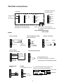
RTD sensors (Celsius or Fahrenheit-scaling)
Pt100 4W (4-wire)
Pt100 3W (3-wire)
Pt1000 4W (4-wire)
Pt1000 3W (3-wire)
Ni100 4W (4-wire)
Ni100 3W (3-wire)
Potentiometer
resist
0-5 kΩ
2-wire
Thermocouples (Celsius or Farenheit scaling)
tc-b
B-type
tc-c
C-type (former W5)
Chr-Co
Chropel-Coppel Chromel
Tc-d
D-type (former W3)
tc-E
E-type
tc-G
G-type (former W)
tc-J
J-type
tc-k
K-type
tc-L
L-type (former J/DIN)
tc-n
N-type
tc-r
R-type
tc-S
S-type
tc-t
T-type
Ir 140
K-type IR-sensor
Ir 440
K-type IR-sensor
PEAk (➤)
Min-/ Max- memory selection. On=in use, Off = not in
use. Indication lights M1= min. M2= max.
CALibr (➤)
Factory settings
SEtCod (➤)
Secret code settings. See chapter 'Settings of secret
codes' page 13.
SLOt b (➤)
Settings of optional cards for slot B. See chapter
'Output signals' pages 11-12.
SLOt C (➤)
Settings of optional cards for slot C (relay- and I/Ocards). See chapter ' Alarms' pages 8-9.
SAVE (➤)
Save changes and exit with SAVE and press ➤-key.
Undo (➤)
Return to previous values with Undo and ➤-key.
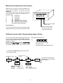
Dec (➤)
Number of decimals in display. Select 0…5 with ▲▼keys and accept with ★-key.
If configuration state contains parameters not
mentioned in this manual, you can pass them by
arrow keys. Additional parameters will be upgraded to manual periodically.
Lo, Hi (➤)
Display scaling for process inputs. You can set display
by Lo-value input equal to 4 mA (0 mA or 0 V) and by
Hi-value equal to input 20 mA(10 V), f.ex. 4 mA=0.0
and 20 mA=100.0.
You may scale also part decimals, f.ex. 500,25,
although amount of decimals is set separately.
7