1
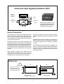
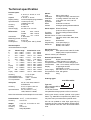
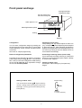
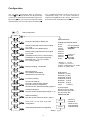
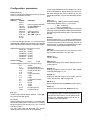
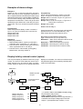
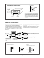
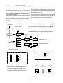
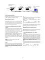
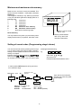
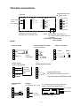
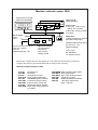
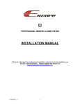
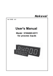
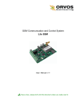
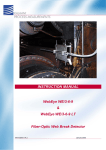
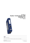
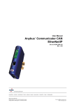
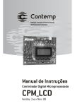
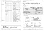
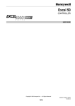
Nokeval
No 221101
User's Manual
Universal Input Digital
Panelmeter
Model 2021
1
Contents
General Description ......................................................................................................... 3
Dimensions ...................................................................................................................... 3
Universal input digital panelmeter 2021 ............................................................................ 3
Technical specification ..................................................................................................... 4
Ordering types .............................................................................................................. 4
Front panel and keys ........................................................................................................ 5
Configuration .................................................................................................................
Reset of configuration parameters .................................................................................
Setting of alarm value ....................................................................................................
Setting of alarms ...........................................................................................................
5
5
5
5
Configuration ................................................................................................................... 6
Starting: ........................................................................................................................ 6
Configuration parameters ................................................................................................. 7
Input selection .............................................................................................................. 7
Alarm functions ................................................................................................................ 8
General description .......................................................................................................... 8
Alarm card connections .................................................................................................... 8
Alarm settings by front panel keys .................................................................................... 8
Selection of alarm card and relay-function settings ........................................................... 9
Card type ...................................................................................................................... 9
Main menu .................................................................................................................... 9
Shifting in menu ............................................................................................................ 9
Examples of alarm settings: ........................................................................................... 10
Display hold by external control (option) .......................................................................... 10
Output 0/4..20 mA (option) ............................................................................................. 11
Output connections ..................................................................................................... 11
Serial output RS-485/RS-232 (option) ............................................................................ 12
Serial protocol (SCL) ................................................................................................... 13
Minimum and maximum value memory ........................................................................... 14
Reset memeory .......................................................................................................... 14
Setting of secret codes (Programming stage/ alarms) .................................................... 14
Terminal connections ...................................................................................................... 15
2-wire 4-20 mA ........................................................................................................... 15
Potentiometer ............................................................................................................. 15
Card slots ...................................................................................................................... 15
Voltage 0-10V .............................................................................................................
Current intput 0/4..20 mA ............................................................................................
Thermocouples and mV ..............................................................................................
Pt-100 3- and 4-wire ....................................................................................................
15
15
15
15
Panelmeter 2000 construction ....................................................................... 16
2000 series input and option cards: ............................................................................ 17
Modular indicator serie 2000 .......................................................................................... 17
•••
Manufacturer:
Nokeval Oy
Yrittajakatu 12
37100 Nokia, Finland
2
Tel. +358 (0)3 342 4800
Fax. +358 (0)3 342 2066
Universal input digital panelmeter 2021
3-way
galvanic
isolation
5620.0
*
Alarms
1-4
24 VDC,
max. 150 mA
RS-485/232
Input
6-digit display enables to show
easily measurements which require large number values, f.ex.
sea level height 105.000 m
Output
Power supply
General Description
Analog conversation is made by 16 bit AD converter
(resolution 1/64000) display can be damped by digital
filter.
Panelmeter 2021 is extremely versatile instrument.
Almost all sensor inputs are programmable like
thermocouples, resistance inputs, process inputs,
mV and potentiometer inputs. Meter provides 24 VDC,
150 mA power for sensors.
Separate secret codes for entering program stage and
settings of alarms. Minimum and maximum display is
as standard, optional hold of display by external
contact.
Meter has three slots, one for inputs ( obligatory) and
two additional slots for output, alarms or serial signal.
By changing input card you can get another instrument
like pulse meter (2051) or strain gage meter (2041) etc.
Changing input card changes meters model number;
each meter has its own data sheet and instruction
manual.
Two alternative power supplies, line voltage 85..240
VAC or 12..32 VDC and 24 VAC. Both are isolated from
inputs and outputs. Terminal connectors are colour
coded in order to avoid erronous connections.Front
panel rating is IP65.
Meter program supports many additional card
combinations. Furnishing the meter needs no
calibration, only the sensor choices and corresponding settings has to be made by front panel keys.
Dimensions
96
case corners have pins
which help installation. Pins
centralizes meter into panel
cut out made with DIN-tool
105
48
ø2,0
6
Panel cut out
43.5 (h) x 90.5 (w) mm
3
10
Gasket (IP65)
Technical specification
Process inputs:
Linear
Squared
Display scaling
Input resistance
Accuracy
Linearity
Sensor supply
Alarms:
Total
2000-REL2
2000-REL3
2000-I/O
Hysteresis
Reset
Contact
0..20 mA, 4..20 mA, 0..10 V
-10..+10 V
0..20 mA, 4..20 mA
On whole display range, 999999
current inputs 50 Ω
voltage inputs 1 MΩ
0.02% FS
0.005% FS
24 VDC, max. 150 mA
Serial output: RS232 or RS485,
(both in a same output card)
Functions
Only for reading measured values
Addresses
0-127
Number of units 31 units in same RS485
Baud rate
300, 600, 1200, 2400, 4800, 9600,
19200
Protocol
Nokeval SCL
Programming
Front panel keys (4)
Distances
RS232, max 10-20 m
RS485, max 1000 m
RTD sensors:
Pt100
-200...+700°C
Pt1000
-200...+700°C
Ni100
-50... +170°C
Connection:
3- and 4-wire
Measuring current 0.25 mA
Accuracy
0.05% FS
Linearity error
< 0.05°C (-200..700°C), Pt100
Thermocouples:
12 linearized thermocouples
TC
E
J
K
L
T
N
R
S
C (W5)
D (W3)
B
G (W)
Whole range
-100.... 900°C
-150.... 900°C
-150.... 1350°C
-100.... 900°C
-150... 400°C
0.... 1300°C
0.... 1700°C
0.... 1700°C
0.... 2200°C
0.... 2200°C
400... 1700°C
1000... 2200°C
Accuracy
Compensation error
Line resistance effect
TC cut protection
Max 4 alarm relays
2 change over relays, max 230 V, 2A
3 closing contacts max 230V, 2A
4 I/O ports max. 36 V,100 mA
0-100%
Automatic or manual
Closing or opening software selection
Special functions:
Display hold
With optional card 2000-I/O, holds
display value, output and alarms
Max/min memory as a standard
Linearization error
< 0.2°C
-50... 900°C
< 0.2°C
-50... 900°C
< 0.4°C -40... 1300°C
< 0.4°C
-50... 900°C
< 0.2°C
-150...400°C
< 0.2°C 0.... 1300°C
< 0.3°C 400... 1700°C
< 0.3°C 300... 1700°C
< 0.3°C 400... 2200°C
< 0.3°C 500... 2200°C
< 0.3°C 400... 1700°C
< 0.4°C 1000. 1700°C
General specifications
Input filter
Digital, user selectable
A/D-converter
16 bits (64 000), uni-or bipolar
Temperature drift 0.0004 %/°C with voltage input
Led indicators Leds 1..4 for alarms, min/max-Leds
Display
6-digit bright red LED
digit height 14.5 mm
Power supply
85..240 VAC or 12..32 VDC/24VAC
Front protection IP65, with gasket
Weight
240 g
0.1 % of span
0.05°C /°C
<100 Ω, no effect
Upscale
Ordering types
2021-REL2-24VDC
mV-inputs:
Accuracy
Input resistance
25, 55, 100, 1000, 2500 mV
and 5000 mV
0.01% of span >100 mV
0.02% < 100 mV
25, 55, 100 mV: >1 MΩ
1000, 5000 mV: ≈ 800kΩ
Type 2021
Alarm card 2000-REL2
Supply voltage
12..32 VDC, 24VAC
Last parameter always power 24 VDC or 230 VAC
Order types doesn't contain optional card symbol
'2000'. e.g. 2000-REL2 is specified only REL2. Unit
may have one input card and two optional cards.
Note! User selectable scale multiplier for max valule
Potentiometer: 0..5 kΩ, 2 wire connection
Accuracy
0.05 % FS
Output:
max. load
Accuracy
Scaling
Unit can be updated to other input types only by
changing the input card and adding needed option
cards. Optional cards are same for all 2000-series
units.
0..20 mA, 4..20 mA or 0..10V
650 Ω
0.05 % FS
freely adjustable
4
Front panel and keys
Conf-light indicates
configuration stage
M1 min memory led
M2 max memory led
Alarm lights A1..A4
5620.0
Selecting between options
*
Exiting
Entering
Checking of alarm value
First pressing of ➤ key shows setpoint of alarm one
(A1), correspondingly second pressing shows setpoint
of alarm two (A2) etc. Alarm indication light blinks in
display informing that alarm level is displayed (if you do
not touch keys during 8 seconds display returns to
normal state automatically).
Configuration
You can enter configuration stage by pressing two
seconds ▲ and ★ keys at same time. In config state
scaling of display, sensor selection and alarm mode
are chosen.
See closer in chapter programming.
Reset of configuration parameters
Preventing of entering alarms (secret code)
If you have set secret code for alarms you must feed it
before you can change alarms (see chapter ”settings
of secret codes” Page 8).
Forgotten secret code may be reset by connecting
power supply and pressing ▲,▼ and ➤ -keys at same
time. Then you can enter configuration state entering
secret code ▲▲▲▲▲▲ when requested. Change
secret code and exit by SAVE.
Change of alarm value
See chapter ”Alarm settings by front panel key”
Page 8.
Setting of alarm value
Number setting
You can set alarm value by ▲▼-keys number by
number. Setting starts from largest number from
left to right. You may go to next number by ➤ -key.
Exit by ★-key.
400.00
Numbers
0...9 and , (decimal)
5
Configuration
key. Hysteresis and alarm mode can be set only in
configuration stage. You can cancel changes by
selecting text UnDo when all is set up, exit by ★ key
and when SAVE is displayed, press ➤ key.
You can enter configuration state by pressing 1
seconds ▲ and ★ keys at same time. By arrow keys
you can move upwards and downwards in main menu.
By pressing ➤ key you can enter configuration state
at wished point.You can exit to previous state by ★ -
+
*
Start configuration
Input
Input selections
DEC
Lo
Hi
FILtEr
Number of decimals in display 0-5.
Voltage and current inputs
Display scaling with minimum input signal.
e.g. 4 mA.
(Zero shift for non scalable inputs)
25 mV
55 mV
100 mV
1000 mV
2500 mV
5000 mV
4-20 mA
0-20 mA
0-10 V
Display scaling whit maximum input signal.
e.g. 20 mA.
(multiplier function for mV- and R inputs)
Digital filter for input signal (damping)
selectable 0.01...1.0 (1.0= no filter)
0.2 = factory setting
DISP
Display averaging, 1-8 samples
PEAk
Min/max function
On=enabled, Off=disabled
Indicators M1=min, M2=max
CALibr
For factory settings
SETCod
SLOT b
Output /serial signal
See also section 'Output signals' pages 11-12.
SLOt C
Alarm level setting
See also section 'Alarm functions', page 8.
lin = OFF
RTD-sensors:
Pt100 4W (4-wire)
Pt100 3W (3-wire)
Pt1000 4W (4-wire)
Pt1000 3W (3-wire)
Ni100 4W (4-wire)
Ni100 3W (3-wire)
resist
0-5 kohm
Thermocouples:
tc-b, tc-c, Chr-Co, Tc-d,
tc-E, tc-G, tc-J, tc-k, tc-L
tc-n, tc-r, tc-S, tc-t,
Ir 440 and Ir 140
CELSIU
Save with ➤ key and exit from
configuration
FArENH
Undo changes and exit from configuration
UnDo
Return
6
Square root
selection
sqr = ON
* Bipolar e.g. ± 25 mV
** Unipolar e.g. 0-25 mV
Unipolar measurement has double
accuracy on positive side
Secret code settings:
ALCode= Code for alarm settings
CFCode= Code for configuration
See also section 'Secret code setting' page 14.
SAVE
mV-input accepts
both Bipolar* and
Unipolar**
Celsius or
Fahrenheit
Will show only
for temperature
measurements.
Configuration parameters
In mV-ranges Hi-setting acts as multiplier, f.ex. range
is 25 mV and Hi=3,50, display shows 87,5 (25 x 3,5).
Lo value changes zero level ± setpoint by mV and
temperature sensors. Typical use is eliminating sensor
error.
Undo, Save (➤)
Exit from configuration state without saving changes
(Undo) or save and exit (Save).
Input selection
Input (➤)
Display
25 mV
55 mV
100 mV
1000 mV
2500 mV
5000 mV
4-20 mA
0-20 mA
0-10 V
IR-140
Filter (➤)
Display filtering. Filtering damps restless display.
Value setting between 1(min) ...0.010 (max).
1.000 = no filtering
0.200 = normal filtering
e.g. Filter = 0.2. The filtered display value is composed
summing 1/5 (20%) the latest measurement result and
4/5 (80%) the previous display value. Filter works liked
RC-filter
Input type
mV-input gives possibility
to select Bipolar or
Unipolar input
mA-input can be
Srq = OFF linear
Srq = ON squared
DISP (➤)
Display update rate 0..7; 0 = display is updated after
each measurement (measurement rate of on thermocouples 4 times/second and on the other sensors 12
times/second), 7 = display is updated after every eigth
measurement, averaging those eight results.
0..10 V input setting works also -10..+10 V input range.
Bipolar display ± 99999, Unipolar works only on positive
side but gives double resolution compared to bipolar.
RTD sensors (Celsius or Fahrenheit-scaling)
Pt100 4W (4-wire)
Pt100 3W (3-wire)
Pt1000 4W (4-wire)
Pt1000 3W (3-wire)
Ni100 4W (4-wire)
Ni100 3W (3-wire)
Potentiometer
resist
0-5 kΩ
2-wire
Thermocouples (Celsius or Farenheit scaling)
tc-b
B-type
tc-c
C-type (former W5)
Chr-Co
Chropel-Coppel Chromel
Tc-d
D-type (former W3)
tc-E
E-type
tc-G
G-type (former W)
tc-J
J-type
tc-k
K-type
tc-L
L-type (former J/DIN)
tc-n
N-type
tc-r
R-type
tc-S
S-type
tc-t
T-type
Ir 140
K-type IR-sensor
Ir 440
K-type IR-sensor
PEAk (➤)
Min-/ Max- memory selection. On=in use, Off = not in
use. Indication lights M1= min. M2= max.
CALibr (➤)
Factory settings
SEtCod (➤)
Secret code settings. See chapter 'Settings of secret
codes' page 13.
SLOt b (➤)
Settings of optional cards for slot B. See chapter
'Output signals' pages 11-12.
SLOt C (➤)
Settings of optional cards for slot C (relay- and I/Ocards). See chapter ' Alarms' pages 8-9.
SAVE (➤)
Save changes and exit with SAVE and press ➤-key.
Undo (➤)
Return to previous values with Undo and ➤-key.
Dec (➤)
Number of decimals in display. Select 0…5 with ▲▼keys and accept with ★-key.
If configuration state contains parameters not
mentioned in this manual, you can pass them by
arrow keys. Additional parameters will be upgraded to manual periodically.
Lo, Hi (➤)
Display scaling for process inputs. You can set display
by Lo-value input equal to 4 mA (0 mA or 0 V) and by
Hi-value equal to input 20 mA(10 V), f.ex. 4 mA=0.0
and 20 mA=100.0.
You may scale also part decimals, f.ex. 500,25,
although amount of decimals is set separately.
7
Alarm functions
Alarm settings by front panel keys
Relay indication lights A1...A4
General description
Panelmeter 2021 is provided with unexceptionally
many versatile alarm functions and therefore it has
plenty of basic selections. When basic selections
are done in config state, normal use with front
panel keys is very simple.
5620.0
*
Alarm cards:
REL 2 =
two relays with changeover contacts
(grey connectors). You may use
two cards (4 relays). Second card is
mounted slot B.
REL 3 =
three relays with closing contacts. Only
one card for slot C. Grey connectors.
2000-I/O =
Checking of alarm value
Pressing ➤ once shows setpoint of alarm one (A1),
correspondingly second pressing shows setpoint of
alarm two (A2) etc. Alarm indication light blinks in
display informing that alarm level is displayed (if you
do not touch keys during 8 seconds the display
returns to normal state automatically).
Preventing of entering alarms (secret code)
If you have set secret code for alarms you must feed
it before you can change alarms (see chapter ”settings of secret codes” Page 14).
four I/O ports (logic alarm, green
connector). Only one card in slot C.
Grey connectors are used for power 230 VAC, 2A and
green connectors for 36 VDC, 100 mA.
Changeing alarm value
First pressing of ➤ key shows setpoint of alarm one
(A1), second pressing shows setpoint of alarm two
etc. When indication light (A1..A4) blinks you can
change alarm level by pressing ▲ or ▼-key. You can
change setpoint of relay in question with keys ▲,▼,
➤. Accept change by ★-key (if you do not touch keys
during 8 seconds display returns to normal state with
automatically and save with same made changes).
Alarm type, hysteresis, etc. must be
done in configuration state.
Removing electronics from
case:
Press meter gently behind front
plate and draw front frame
forwards at upper edge.
Alarm mode, hysteresis and other settings are done
in configuration state.
Slot B Slot C
Alarm card connections
Input card
Indicators A1-A4
in front panel
6
5
4
3
2
1
Slot A
Slot B
6
Nc 5
No 4
3
Nc 2
No 1
Slot C
2000-I/O
Relay card REL3
Relay card REL2
6
5
4
3
2
1
4 logic outputs
or inputs
A1
Max.
230 VAC,
2A
A2
7 8 9
Optional cards are named as Slot C or B
8
6
5
4
3
2
1
A1
A2
A3
Max. 230 VAC,
2A
6
5
4
3
2
1
Max. 36 V,
100 mA
A1
A2
A3
A4
Com
Selection of alarm card and relay-function settings
Meter has unexceptionally versatile alarm functions. In
initial settings you can select type of alarm card (2, 3
or 4 relays) and into which slot it will be placed. You
have to set alarm level, hysteresis etc for every relay.
When initial settings have been made, you can
easily set alarm levels by front panel keys (see
chapter ”alarm functions” Page 8). You can prevent
entering to alarm change state by secret code (see
chapter ”settings of secret codes”, page 14).
Alarm card must always be mounted to slot C. If you
need 2 alarm cards (2000-REL2) i.e. 4 changeable
relays, second alarm card must mounted to slot B.
Shifting in menu
You shift in menu to next level (to right) in programming
stage by ➤-key. By ★-key you return to previous level
or to main menu. Excample below describes only
settings of one relay (relay numbers 1-4).
Main menu
Slot b
★
Card type selection
Slot B or C
Relay
number
★
Setup
Slot C
Hold
Hold= not used in alarm selection
OFF
Disables unused relay indicator
light with ★-key.
Alarm level setting (Level)
★
ALArm
rELAy1
Level
A1
Card not
installed
★
Card 4
rELAy2
A2
Card 2
rELAy3
A3
Off
rELAy4
A4
100.0
★
Serial
Hysteresis
selection
HyST
1.0
AL Lo = Low level
AL Hi = High level
Type
AL Lo
AL Hi
Alarm Reset:
Unit remembers which card is in use and skips
direct to selection of relay number (relay 1). You
can select new card in setup-point by holding down
▲ or ▼-keys 3 seconds. Point OFFand then ★-key
excludes the card from use. Front panel indication
lights A1..A4 correspond to realay numbers 1..4.
Serial = serial card, see chapter 'serial output RS485/RS-232'.
Slot B tai Slot C = Card slot B or C
Manually from front
panel or automatic
Reset
User
Auto
Relay direction:
Contact
No=normal open
Nc=normal closed
★
Nc
No
★
Back to main menu
Card type
Card 2 =
2 alarm relays with changeover contacts, 2000-REL2. Second card may be mouted also to slot
B, if you need four alarms. Front panel indication lights: Relay 1 = A1, Relay2 = A2 . Relays of
slot B use indication lights A3 = relay3 and A4=relay4.
If you cannot set four relays, Slot B has not alarm card but some other card.
Card 4 =
Card has 3 or 4 relays, 2000-REL3 = 3 relays, logic output 2000-I/O=4 alarms.
panel indications lights A1…A4 according to relays 1..4=A1..A4.
Must always be mounted to slot C.
Next page shows 2 examples of alarm settings.
9
Front
Examples of alarm settings:
Example 1.
Display 0..100.0 °C and one high alarm (HI) 60°C.
Alarm must get off when temperatur goes down to
58°C. Display has been ordered with two alarm relays
and with two changeover contacts (Relay card REL2).
HI level means closing relay indication lamp when
temperature exceeds 60°C. Alarm will get off when
temperature goes below 58°C and relay will open.
’Alarm-OFF’ turns out unused front panel indication
lights.
Programming:
Slot C-Setup-Card4-Relay1-Alarm-Level 260Hyst1.0-Type AL Hi-Reset Auto-Contact Nc.
Relay2-Alarm-Level150.0-Hyst 0.5-Type-Al LoReset Auto-Contact no
Relay3-Alarm-Level120.0-Hyst1.0-Type-Al LoReset User-Contact nc
Relay4-Alarm-OFF
Alarm reset of relay 3:
Programming:
Slot C-Setup-Card2-Relay1-Alarm-Level 60.0Hyst -2.0-Type-Al Hi-Reset-Auto-Contact-No.
Relay2-Alarm-OFF
Relay3-Alarm-OFF
Relay4-Alarm-OFF
Press front panels ➤-key three times until indication
light A3 turns on. You can reset alarm by *-key.
Other relays will reset when alarm turns out.
Description of Type-Reset-Contact-User
Type =selection low (Lo) or high alarm (Hi)
Reset-Auto = Alarm to be reset when value is not at
alarm level anymore
Reset-User = Alarm to be reset by front panel
Contact-No = Normally open contacts of relay
Contact-Nc = Normally closed contacts of relay
Example 2
Display range 0-600°C
1. High level alarm 260°C, opening contact (NC),
automatic reset. Hysteresis 1.0°, Use relay 1.
2. Low level 150°C, closing contact (NO), automatic
reset, Hysteresis 0.50°C, use relay 2
3. Low level 120°C, manual reset, opening (NC).
Manula reset, use relay number 3.
Display hold by external control (option)
display is in hold state. You can turn out the unnecessary indication lights on front panel by selecting OFFmode for unused relays.
You may lock display by external contact or by logic
control. You have to mount 2000-I/O card to slot C.
Other I/O-lines may be used for alarm functions.
Output, display or alarms do not change state when
Main menu
Disable unused
I/O-port
Slot b
★
OFF
★
Slot C
Setup
Accept and exit to
main menu
★
Hold
Lo HoL
*)
HI HoL
Card 4
rELAy1
Alarm
A1
Relay1=I/O-port 1
Relay 2=I/O-port 2
Relay 3=I/O-port 3
Relay 4=I/O-port 4
Indicator lights A1..A4
A2
rELAy2
A3
rELAy3
A4
rELAy4
*) In position 'Alarm' select Hold to display with ▲key and select relay function:
Hold Lo Hol=0 (Closing contact)
Hold Hi Hol=1 (Opening contact or Logic function '1')
Card 2000-I/O accepts voltage input 5-32 VDC
stage='1' (corresponds open contact), '0'<1V.
10
Display hold by external contact
Card 2000-I/O
6
5
4
3
2
1
Display hold
when contacts
are closed
5620.0
Slots B or C
*
Output
A1 Hold
A2
A3
A4
Com
You can program hold function to input lines
1-4. Closing contact or logic control 5-24 V.
Without control input is in measuring state
(state 1). Closing contact locks display.
You may program other I/O ports for alarm
functions.
Alarms
Output 0/4..20 mA (option)
Meter may be provided with isolated output, ranges 0/
4..20 mA or 0..10 V, which are programmable.
You can mount output card to slot B or C (default B).
Calibration information is saved to card and no calibration is needed in configuration. You need not select
card in programming because meter recognizes the
mounted card.
Programming: select slot B in main menu. Press ➤
key. Display shows 4-20. See below description.
Main menu
0-10V
★
0-20
4-20
Slot B
Lo
0.0
Hi
100.0
Select output scaling for 0 or 4 mA
OFF
★
★
Output function can
be disabled without
removing the output
card.
Accept and return
to main menu
Select output scaling for
10 V or 20 mA
★
Output connections
(option)
Passive 2-wire output 4-20 mA
6
5
4
3
2
1
Card slot B
+
0-10V
6
5
4
3
2
1
+
0-20 mA
4-20 mA
Card slot B
6
5
4
3
2
1
4-20 mA
+24 V
Card slot B
11
Serial output RS485/RS232 (option)
In config state you can first select card type (serial)
mounted to slot B or C and then address and Baud rate.
baud rates are: 300, 1200, 2400, 4800, 9600, 19200
and addresses 0...127.
Program remembers card type mounted, if it has been
saved by save command when leaving program. In
case you can not choose serial card, slot has
automatically recognized card (plug and play).
Meter may be provided with optional serial output and
you can read measurements by e.g. PC. Display
programming can not be made via serial port. Additional
card provides serial signal RS232 and RS485, only one
of those can be selected.
Serial signal is isolated from both input signal and
power supply. Meters with RS485 can be max. 31 in
same loop and longest distance 1000m. RS232 enables only connection of one meter and max. distance
10..20 m.
Main menu
Slot b
Back to main
menu
You can enter card selection stage by pressing ▲ or ▼
key 3 seconds.
★
Unit remembers card type mounted, once selected and
you can pass selection of card setup next time and move
direct to card configuration state.
Setup
Slot C
★
Serial
★
Serial signal
not used
Address
Ad 0
Bdrate
19200
Serial address
selection 0...127
OFF
Card 2
Baud rate selection
300...19200
Card4
★
Terminal connections:
Card slot A
6
5
4
3
2
1
A
B
RS-485
Term
Fs
6
5
4
3
2
1
2000-RS
Serial output
on off
Input
Serial card
TxD
Com
RxD
Card slot B or C
R S232
R S485
RS485
other units on bus last unit on bus
(Factory settings)
off
off
off
Term
Fs
Term
Fs
Term
Fs
12
on
on
on
When using serial signal RS485 last unit
must be terminated 110 ohm resistor. You
can make termination at terminal connectors or connecting jumper J1 to ON position.
Termination 110 ohm
on last units
Address 2
5620.0
Address 1
5620.0
*
Address 0
Data acquisition
with PC
5620.0
*
*
RS485
Twisted pair cable
Serial communication
e.g.
One wants the measurement result from the display
unit address 1. An inquiry is sent:
MEA CH 1 ? (ASCII codes shown for <BCC>
calculation)
Baud rate: 300, 1200, 2400, 4800, 9600 and 19 200
1 Start, 8 Data and 1 Stop bit, no parity.
Serial protocol (SCL):
MESSAGES: When asking the measurement data
from the panelmeter 2021 through the serial port, a
command sequence which is in accordance with the
SCL protocol is used for the inquiry.
M E A
C H
1
?<ETX>
4Dx45x41x20x43x48x20x31x20x3F x03
<BCC>
= 6F
(XOR operation is presended with a character x) (ASCII
code 20h corresponds to space character)
<ADDR+80h>COMMAND STRING<ETX><BCC>
So the following bytes are sent to 2021:
81 4D 45 41 20 43 48 20 31 20 3F 03 6F
<ADDR>
The first byte character to be sent contains the address
of the destination device and at the same time functions as the start indicator of the command. The
uppermost bit of this byte is set, in other words 80H
(128 in decimal) is added to the address.
RETURN MESSAGE: The answer from the panelmeter
2021 is obtained in the following format:
<ACK>RETURN MESSAGE<ETX><BCC>
COMMAND STRING: When measurement data is
requested, the actual command is: MEA CH 1 ? , in
which 1 means the channel number. (there is only one
channel in the panelmeter 2021 so the number is
always 1).
<ACK>
The first byte of the answer contains the start of the
answer <ACK> (ASCII-code 06h) and the answer
itself, endmark <ETX> (ASCII- 03h) and the checksum
of the answer which is calculated from all the byte
characters of the answer including <ACK> and <ETX>.
2021 counts the checksum in which case the receiver
does not need necessarily to care about it.
e.g.
e.g. When a measurement result is for example 21.3,
it will be obtained from the panelmeter in the following
form
<ACK> 2
1 .
3 <ETX> <BCC>
Answer: 06 32 31 2E 33 03
1B
<ETX>
<ETX> mean the end mark of the command,
ASCII character 03h.
<BCC>
Finally the checksum is calculated using XOR operation on the byte characters of the actual command
including the ETX, excluding ADDR byte. In the example the ASCII codes have been presented in hexadecimal.
13
Minimum and maximum value memory
Meter has min. and max. memory as standard. This
function must be enabled in config state, parameter
PEAK=ON.
You can glance values by ➤-key. When you press the
➤ key, the indication lights above display blink on in
following order:
1.
A1
alarm level
2.
A2
alarm level
3.
A3
alarm level
4.
A4
alarm level
5.
M1 Minimum value memory
6.
M2 Maximum value memory
7.
None back to measuring stage
A1
A2
A3
A4 M1 M2
5620.0
*
Memory can be viewed
with ➤ -key
Reset memeory
Memory can be resetted
with ★ -key when indicator M1 or M2 blinks.
You may reset memory when you press ★-key when
display shows memory in question, either M1 or M2.
Setting of secret codes (Programming stage/ alarms)
You can enter secret code by pressing six time keys
(1-4) in wished order (lines goes forward in display).
Setting must be repeated in same order before new
setting is accepted.
Example: Press one after another keys ▲ ▲ ★➤▲▲
★➤▲▲. You may think the keys
and once more ▲ ▲ ★➤▲▲
as numbers from left to right 1,2 3,4 in order to help
recording and remembering.
★
e.g.
1
2
3
4
Input code ▲ ▲ ★➤▲▲
and once more.
Example number value would be 113411.
In menu position SETCod press ➤ key and move
on to selection stage.
Accept new code
and exit
Main menu Back
SEtCod
★
★
ALCode
On
CFCode
OFF
Select secret code to set:
CFCode
config
ALCode
for alarm levels
__-_
Type new secret code twice.
(Accepts new value only after
second input)
Back
Secret code:
ON = enable
OFF = disable (default)
14
Terminal connections
Specified instructions
for optinal cards.
Card slots
Output
Inputs
(+)
Sensor supply
24 VDC
max. 150 mA
(-)
6
5
4
3
2
1
6
5
4
3
2
1
Slot A
Relays (REL2)
+ V
Com
Nc
+ mA
No
Nc
No
Slot B
6
5
4
3
2
1
+
2-wire
transmitter
Short 3-4
Sensor supply
24 VDC, max 150 mA
6
5
4
3
2
1
Pt100 3- and 4-wire
6
5
4
3
2
1
0...20 mA
4...20 mA
3-wire
4-wire
Thermocouples and mV
6
5
4
3
2
1
+ 24 VDC
Transmitter
output 3-wire
Com
0..20 mA
4..20 mA
Voltage
0..5 kΩ
0..10 V and -10..+10 V
+
A3
Relays A1-A3
+
Potentiometer
6
5
4
3
2
1
A2
7 8 9
Current intput 0/4..20 mA
(active transmitter)
2-wire 4..20 mA
+
-
A4
A1
Power 85..240 VAC, Grey connector
12..32 VDC, 24VAC, green connector
(no polarity)
Colour codes: Gray 230 VAC
Green 24 VDC
Inputs:
6
5
4
3
2
1
6
5
4
3
2
1
A3
Slot C
Card slot A only for input card.
Slots B and C for optional cards.
+ 6
- 5
4
3
2
1
Relays (REL3)
6
5
4
3
2
1
-
Thermocouples, mV,
25, 55,100, 1000 mV, 2,5 V ja 5 V
+
Input selection in configuration mode
0..10 V input requires moving jumper J1 to
position 1-2, for other inputs select 2-3.
0..10 V input
J1
1 2 3
1 2 3
Default (2-3)
-
1 2 3
0..10 V
+ -10..+10 V
Input card 2021-MU
15
Panelmeter 2000 construction
The 2000 series panelmeters are modular and easy to
assemble. According to customers wishes. The basic
construction consists of mother board with tree slots,
A, B and C. Slot A determines meter type and provides
always input signal. Slot B and C are interchangeable.
As factory delivery input signal is always installed into
slot A , mA output into slot B and alarms into slot C. In
case of f.ex 4 alarms and relay card with 2 change-over
contacts (2 + 2 relays) are used, you must place
second relay card into slot B. The slot B is now usable
for other optional outputs.
You can have different types of meters by only
changing the input card in slot A. Data sheet of each
type of meter dictates the possible combinations.
Recalibration of card is not needed; only scaling and
other settings must be set by front panel keys.
All cards have calibration
memory
Slots A-C
A
B
C
Power supply 11. .32 VDC
(Green connector)
or 85...240 VAC
(Grey connector)
Changeing meter type:
Input card is placed always in
slot A. By changing input card
you can get an other type of
meter. You can change meter
with pulse input to meter with
current input, thermocouple,
strain gage etc.
Additional slots:
Additional cards provide output
4..20 mA, alarms, serial interface, BCD output etc. Meter
data sheet dictates possible
combinations. Grey connectors
allow line voltage 110..240 VAC
(relay contacts).
Power supply:
There are two different mother
boards, for power supply
85..240 VAC and 12..32 VDC.
The latter mother board accepts 24 VAC.
Removing meter from case:
Press gently case behind front panel
and draw frame outwards gripping
upper part of frame.
Loose connectors and front panel,
draw meter out from front. You may
remove mother board from rear by
opening four screws in corners of case.
16
Modular indicator series 2000
5 digit (2011) or 6-digit
bright red LED display
Option cards
(slots B and C):
E²
6543.21
Alarm cards:
2 relay card, 4 alarm types,
change over contacts
3 relay card, closing contacts
4 I/O-ports
E²
DAC
Sensor supply:
24VDC,
150 mA
2021
E²
2011
E²
ADC
Process inputs (model 2011):
0..20 mA, 4..20 mA
0..5/10 V
Potentiometer 100Ω..5kΩ
uP
Input card contains:
- microprocessor
- bus control
- keys control
- display control
Model 2011:
2 relays change over contacts
(also with remote reset)
Output cards (not for 2011):
0/4..20 mA, 0..10 V
RS232 or RS485
Power supply:
85..240VAC or
12..32 VDC / 24 VAC
Model 2021 contains also process inputs but it can measure RTD-sensors and thermocouples. 2021 has very accurate and fast A/D-converter (16 bit 1/64 000).
2000 series input and option cards:
2011-IN
2021-MU
2031-IR
2041-STG
2051-Hz
2061-CNT
2066-TIM
2071-RS
2081-BCD
2000-BASE
2000-REL2
2000-REL3
2000-OUT
2000-RS
2000-I/O
Process input
Multi input
Infrared sensor input
Strain gage measurement
Scaleable frequency indicator
Counter input (max 5 kHz)
Timer function, s/min/h ext.
Serial input RS232 / RS485
BCD-, Gray- binary code input
(1-5 digits)
17
Base card with power supply
Alarm card, NO/NC
Alarm card, Closing contacts
Output card, U and I
Serial output RS232 or RS485
4 pcs input /output ports
(60 V / 100 mA)
Notes:
18
Notes:
19
Manufacturer:
Nokeval Oy
Yrittäjäkatu 12
37100 NOKIA
FINLAND
Tel.
Fax.
email
http://
20
+358 (0)3 342 4800
+358 (0)3 342 2066
[email protected]
www.nokeval.com