1
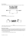
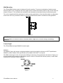
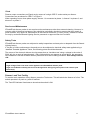
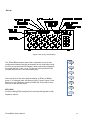
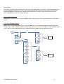
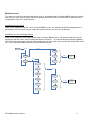
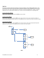
3Pack and 6Pack
User’s Manual
3Pack/6Pack User’s Manual
1
Strand Lighting Limited
Mitchelston Industrial Estate
Kirkcaldy, Fife
United Kingdom
The material in this document is for information purposes only and is subject to change without notice.
Strand Lighting assumes no responsibility for any errors or omissions which may appear in this manual. For
comments and suggestions regarding corrections and/or updates to this manual, please contact your
nearest Strand Lighting office.
El contenido de este manual es solamente para información y está sujeto a cambios sin previo aviso.
Strand Lighting no asume responsabilidad por errores o omisiones que puedan aparecer. Cualquier
comentario, sugerencia o corrección con respecto a este manual, favor de dirijirlo a la oficina de Strand
Lighting más cercana.
Der Inhalt dieses Handbuches ist nur für Informationszwecke gedacht, Aenderungen sind vorbehalten.
Strand Lighting uebernimmt keine Verantwortung für Fehler oder Irrtuemer, die in diesem Handbuch
auftreten. Für Bemerkungen und Verbesserungsvorschlaege oder Vorschlaege in Bezug auf Korrekturen
und/oder Aktualisierungen in diesem Handbuch, moechten wir Sie bitten, Kontakt mit der naechsten Strand
Lighting-Niederlassung aufzunehmen.
Le matériel décrit dans ce manuel est pour information seulement et est sujet à changements sans préavis.
La compagnie Strand Lighting n’assume aucune responsibilité sur toute erreur ou ommission inscrite dans
ce manuel. Pour tout commentaire ou suggestion concernant des corrections et/ou les mises à jour de ce
manuel, veuillez contacter le bureau de Strand Lighting le plus proche.
3Pack/6Pack User’s Manual
2
Table of content
Introduction
4
Specifications
4
Installation
5
Installation Notes
5
Mains Power Input Connections
6
Mains Cable Entry
6
Rear Cable Entry
7
Side Cable Entry
7
Mains Cable Termination
7
Protection
8
Power Distribution
8
Wall Mounting
9
Control Input
9
Data cable termination
10
Dimmer Outputs
10
Service and Maintenance
11
Safety Tests
11
Dimmer Load Test Facility
11
Set up
12
Set Dimmer Level
13
Select Preset 0-9
13
Patch
14
Set Curves
16
Minimum Level
17
Maximum Level
18
DMX Fail
19
3Pack/6Pack User’s Manual
3
Introduction
Strand Lighting 3Pack/6Pack dimmer packs are compact, portable-dimming units, designed for use in
conjunction with lighting control console.
The basic 3Pack/6Pack accepts standard DMX 512 multiplexed digital control input
Specifications
Power Requirements
Voltage: 200 - 260 Volts AC. Frequency: 50 - 60 Hz.
Three phase + Neutral + Earth
3Pack/6Pack dimmer packs must be Earthed for safety in use.
Dimming Capacity
3Pack
Each pack contains three dimmers with one socket outlet per dimmer.
Maximum load 5kW per dimmer - total 15kW per dimmer pack.
6Pack
Each pack contains six dimmers with two socket outlets per dimmer.
Maximum load 2.3kW per dimmer - total 13.8kW per dimmer pack.
Dimmer Output Connections
3Pack
3Pack is available with a CEE17 socket outlet per dimmer.
6Pack
6packs are available with a variety of socket outlets to suit different operating conditions and national
standards. A version without sockets is also available. This version includes a removable panel which
maybe used for mounting outlets of any suitable type.
Two sockets per dimmer are fitted as standard.
Control Inputs
USITT DMX512(1990) multiplexed digital control, via 5 pin XLR connector.
Physical Dimensions (unpacked)
Height: 178 mm.
Width: 483 mm.
Depth: 250 mm.
Weight: 14Kg (approximately)
Environment (Operating)
Temperature: 0°C - 37°C.
Relative humidity: 0% - 90%.
Condensation level: Zero.
3Pack/6Pack are suitable only for use in a dry, internal environment.
Protection Classification
IP30.
Equipment Class
Class 1.
3Pack/6Pack User’s Manual
4
Installation
WARNING
Hazardous voltages are present in 3Pack/6Pack. Ensure that the mains supply is isolated before opening the
equipment for installation or servicing.
Dimmer packs should be installed and serviced only by suitably competent (Electrical) personnel.
3Pack and 6Pack may be installed in three manners:
As free standing units (for temporary installations),
Mounted on a wall (for permanent installations) – refer also to pages 6,7 and 9,
Several packs mounted together in a rack (for hire or touring purposes).
Installation Notes
In order to enhance the reliability of the dimmers, it is recommended that they are operated within the
following environmental limits:
Temperature: 18°C - 25°
Relative Humidity: 60% - 80%
Condensation level: Zero
3Pack and 6Pack dimmers are designed such that Earth leakage currents are minimised, allowing their use
on mains power supplies protected by 30mA Residual Current Devices. However, utilising RCD protection
in dimming installations may present problems. Please contact Strand Lighting for specific advice
The dimmers may emit a slight buzzing noise when in operation. They should be installed away from areas
where such noise would be undesirable.
The physical dimensions of a 6Pack dimmer pack are shown in Figure 1. The dimensions of a 3Pack
dimmer pack are identical.
6 pack
Figure 1
3Pack/6Pack User’s Manual
5
Mains Power Input Connections
3Pack and 6Pack dimmer packs require a nominal mains input at 230V 50Hz AC. This supply may be
either single or three phase (star only), depending on the method of connection. In either case separate
Neutral and Earth conductors are required.
WARNING
3Pack and 6Pack dimmer packs must be Earthed for safety in operation.
The Neutral conductor must have the same (or greater) cross-sectional area, as the Phase conductor(s).
(Triac and thyristor dimmers operate using ‘phase control’. This renders the ‘balancing’ of loads across
phases - and thus a reduction in Neutral currents impossible)
3Pack and 6Pack dimmer packs should be connected to their mains supplies via adequately rated cable, together
with any associated plug and socket connectors. For full power operation the supply must be rated at 60A for single
phase operation, 20A for three phase operation. These ratings may be reduced if the supply protective devices are
selected to limit the current drawn to appropriate limits. Should supply diversity be applied care is required in the
sizing of supply neutral conductors. If in doubt please seek advice from Strand Lighting.
For safety in operation each rack must be fed from an appropriately fused supply.
It is strongly recommended that the mains supply to the dimmers is taken via a local isolating switch, so that the
supply may be easily disconnected for plugging and unplugging of load connectors and for service or maintenance.
All cables, switchgear and protection equipment must be selected and installed in accordance with locally prevailing
electrical regulations.
Mains Cable Entry
The mains input cable will enter the pack either via a Rear Connection Panel, or via one of the Side Plates
– depending on the manner in which the pack is to be mounted:
For wall mounting, side cable entry must be used,
For rack mounting, rear cable entry must be used,
For free standing, either side or rear cable entry may be used, although the rear cable entry is
recommended.
3Pack/6Pack User’s Manual
6
Rear Cable Entry
Remove the Rear Connection Panel. It is secured to the base by two screws, as shown in Figure 2.
6 pack
Figure 2
Side Cable Entry
Remove the selected Side Plate as indicated in Figure 3
6 pack
Figure 3
A 32mm diameter cable entry hole is provided in each Side Plate. Remove the blanking plug from its hole,
and fit a cable gland of the correct size.
Mains Cable Termination
The mains input is connected at a set of screw terminal blocks, situated inside the pack, at the right hand
side (looking from the front of the pack). The terminals will accept cables of up to 16 mm2 in size. If it is
required to connect a 3Pack or 6Pack to a single phase supply, the link bar supplied with the pack should
be used to join the three phase terminals together, as follows (refer to right-hand diagram in Figure 4):
1. Loosen all three phase terminals.
2. Place incoming cable inside terminals and tighten securely.
3Pack/6Pack User’s Manual
7
Figure 4 Mains Termination
WARNING
Do NOT fit the link bar when the pack is connected to a three phase supply
Protection
The mains supply to each dimmer pack must be protected against external overload. Appropriate fuse or
circuit breaker ratings are 60A for single phase supply and 20A for a three phase supply. If the available
mains supply is not capable of providing the full rated currents, the protection device rating must be
reduced accordingly; it will not be possible to use the dimmers with their maximum rated loads.
Protection systems on the supply to each dimmer pack should limit the potential fault current level to 1500A
or less.
Power Distribution
To achieve correct Earthing and mains power distribution, it is recommended that all dimmers and lighting
control equipment within the installation should draw mains power from one central distribution point. This
should be as close as possible to the mains power intake for the site or building. The wiring from the
distribution point to the lighting equipment should ideally be used for supplying power to the lighting
equipment alone, and not to other appliances or equipment.
3Pack and 6Pack must be properly Earthed, both for safety and to ensure correct operation.
It is essential that all Earth connections within the overall installation are at comparable potentials. If this is
not the case, circulating currents may be generated in signal earth connections, possibly leading to
fluctuating light levels and (in some extreme cases) damage to wiring or equipment.
Care should be taken when differing electrical supplies (for example local generation for dimmers, public
mains for control console) are in use or internal mains power distribution is TN-C (combined neutral & earth
conductors)
If in doubt, as to the nature of your local electrical supply arrangements please seek advice from an
authorative person at your site..
3Pack/6Pack User’s Manual
8
Wall Mounting
The 3Pack/6Pack dimmer pack is designed for wall mounting. To prevent overheating of wall-mounted
dimmers when in use, locate the feet of an upper rack for racks to be directly stood on top of each other as
shown in Figure 5. Do not Block the ventilation holes situated on the sides and top of the dimmer pack.
The unit is supplied with fixing brackets for wall mounting applications. Care should be taken to adequately
secure the unit to any surface to which it is mounted and that the surface is suitable for this application.
Figure 5
WARNING
Forced ventilation is advised if racks are mounted within a flight case or similar closely constraining
enclosure.
Control Input
The 3Pack/6Pack accepts DMX512 control inputs:
DMX512
The DMX512 input will accept a multiplexed digital control signal which conforms to USITT specification
DMX512 (1990). Details of this specification are available from USITT on request.
The DMX control input is via a five-pin male XLR type connector. Pin connections are shown in Figure 6. A
five-pin female XLR connector is also fitted to allow a series of 3Pack/6Pack dimmer packs (or other DMX
equipment) to be daisy chained together.
Figure 6
3Pack/6Pack User’s Manual
9
Data cable termination
When required, data cables can be terminated directly to the termination blocks provided inside the
3Pack/6Pack. The internal data cable termination positions are as shown in Figure 7.
Control Cables Assignment (Internal)
Figure 7
Dimmer Outputs
6Pack
Dimmer output connections are by means of socket outlets on all styles of 6Pack dimmer packs, except the
terminal strip version. Two sockets are fitted per dimmer.
When operating from a three phase supply, dimmers 1 and 2 are connected to phase 1, dimmers 3 and 4 to
phase 2, and dimmers 5 and 6 to phase 3.
Plug tops used for dimmer output connections must be of the correct type to match the socket outlets.
It is important that plugs are wired correctly. Figure 8 shows the various types of socket outlets fitted to
6Pack dimmer packs.
Figure 8
3Pack/6Pack User’s Manual
10
3Pack
Dimmer output connections on 3pack are by means of a single CEE17 socket outlet per dimmer.
Connections are as shown for CEE17 in Figure 8.
When operating from a three phase supply, dimmer 1 is connected to phase 1, dimmer 2 to phase 2, and
dimmer 3 to phase 3.
Service and Maintenance
3Pack/6Pack dimmer packs do not require routine maintenance other than external cleaning. However, in
common with all electrical equipment, they should be periodically checked to ensure that they remain in
good condition. Any repairs or maintenance to the internal electronics, or other circuitry, should be carried
out only by authorised Strand Lighting Service personnel or approved Service Providers.
Safety Tests
3Pack/6Pack dimmer packs are subjected to safety inspections and tests prior to despatch from the Strand
Lighting factory.
If, as part of routine maintenance, the packs are to be subjected to electrical safety tests applied using a
‘standard’ Portable Appliance Tester, the following points should be observed:
The nature of the electronic dimmer circuits means that an ‘insulation test’ using a voltage in the order of
500V will give a result of approximately 1.7MΩ. Although this may appear as a test failure, the apparently
low resistance is normal for these dimmer packs and is not due to failing insulation. User safety is not at
risk.
Caution
A high voltage ‘Flash’ test must not be applied to an 3Pack/6Pack dimmer pack.
A high current Earth continuity test must not be applied to the signal ground pins of the control input
connector(s).
Dimmer Load Test Facility
To test the basic operation of any dimmer, press the Test button. This will switch the dimmer to full on. The
switch operates in a push-on, push-off manner.
The Test LED indicator illuminates to show that the switch is ON.
3Pack/6Pack User’s Manual
11
Set up
Figure 9 Set up keys and displays
Set Dimmer
Level
The 3Pack/6Pack dimmer pack offers a selection of set up and
configuration features that are accessed from the front panel using
the four set up keys and LED Display. Menu and setting selections
are made with the + and - keys. To exit any menu press the ESC
(escape) key and OK is the confirmation key.
+/-
Preset
+/-
Patch
+/-
+/-
At the top level of the menu with the display of 3Pack or 6Pack,
press +/- to navigate from Set Dimmer Level, Preset, Patch, Curve,
Minimum Level, Maximum Level and DMX fail. Press OK to enter
into any of that specific menu.
Curve
+/Minimum
Level
+/Maximum
Level
KEYLOCK
Lock by holding [ESC] and [OK] for3 seconds (5th digit dot is ON).
+/-
DMX Fail
Repeat to unlock.
3Pack/6Pack User’s Manual
12
Set Dimmer Level
When a control console is not available, the
dimmer levels on 3Pack/6Pack dimmer systems
can be individually set to a desired level using the
front panel keys. After the selection of +/- key to
the Set Level display, press OK to enter into the
Set Level.
Set all Dimmer Levels
Use “+” or “-“ to change the display to ALL, OK to
confirm setting all dimmer levels. Default is all at
Input, press +/- to select dimmer levels follow by
OK.
Set single Dimmer Level
Use +/- to select channel 1-6, OK to confirm
setting of that particular channel. Default is input,
press +/- to select the dimmer level of that
channel follow by OK.
SET LEVEL
OK/ESC
ALL
+/-
1
OK/ESC
+/-
2
+/-
Input
3
+/-
+/-
1%
4
+/-
+/-
OK/ESC
Output Level Set
+/-
+/-
….
5
+/-
+/-
100%
6
Select Preset 0-9
This menu is to set the content
of a Preset in the range from
Preset 0 to Preset 9. The
preset can be called up during
DMX fail.
Use +/- to select Preset number, OK to confirm and press +/- to
select snaps/edit follows by OK.
Snaps
Snaps is to take a snap shot from the DMX input, when the snaps
display on the LED window, press OK to take the DMX level from the
DMX input.
3Pack/6Pack User’s Manual
13
PRESET
OK/ESC
Edit
1
Edit to change individual
channels within the Preset.
Similar to Set Level, you can
use all or individual channel to
edit a certain Preset.
+/+/-
….
OK/ESC
+/-
9
SNAP
PRESET
STORED
OK/ESC
+/+/-
EDIT
OK/ESC
ALL
+/-
1
OK/ESC
+/-
2
1%
+/+/-
+/-
3
+/-
+/-
….
4
+/-
+/-
100%
OK/ESC
Level Set
5
+/-
6
3Pack/6Pack User’s Manual
14
Patch
This menu is to set either the DMX start address if the dimmer channels are used sequentially or each DMX
address can be patched individually to each dimmer channel.
Use +/- keys to select either “DMX Address Start” or “DMX Address independent” menu.
Select Start DMX address
When in the “DMX Address Start” menu, press the OK key once, the start address is now displayed. Use
the + and - keys to select the start address (1 – 512) for the dimmer pack. When complete, press OK key to
confirm.
Set independent dimmer patch
When in “DMX Address Independent” menu, press the OK key once, the dimmer Channel # is now
displayed on the LED, Use the + and - keys to select the dimmer channel (1 – 6) and then press the OK
key again. Use the + and - keys to select the DMX address (1 – 512) to be assigned to the dimmer channel.
After selecting the DMX address, press the OK key and the selected patch will be recorded. Repeat the
above process until all channels are set.
OK/ESC
PATCH
OK/ESC
1
+/-
START
+/-
+/-
+/-
….
OK/ESC
START
ADDRESS SET
+/-
OK/ESC
INDEP
512
1
+/-
2
OK/ESC
+/-
3
+/-
1
4
+/-
+/-
+/-
+/-
….
5
+/-
+/-
512
OK/ESC
DIMMER
ADDRESS SET
6
3Pack/6Pack User’s Manual
15
Set Curves
This menu is used to select a dimmer curve for any or all the dimmers in a system. There are three dimmer
curves available to choose from Linear, Non-Dim and Square law. When the Curve menu is shown after
pressing the OK key, use the + and - keys to select either the “Curve All” menu for all dimmers or the
“Curve Independent” menu for a single dimmer.
Set Curve for all Dimmers
When in the “Curve All” menu, press the OK key once, then use the + and - keys to select one of the three
curves.
Set Curve for Single Channel
When in the “Curve Independent” menu, press the OK key once, the dimmer Channel # will be displayed,
use the + and - keys to select the dimmer channel (1 – 6) to be set. Press the OK key again followed by the
+ and - keys to select the preferred curve. Repeat the above process until all channels are set.
OK/ESC
CURVE
OK/ESC
1
+/-
ALL
+/-
+/-
+/-
….
OK/ESC
CURVE SET FOR
ALL
+/-
OK/ESC
INDEP
3
1
+/-
2
OK/ESC
+/-
3
+/-
1
4
+/-
+/-
+/-
+/-
….
5
+/-
+/-
3
OK/ESC
INDIVIDUAL
DIMMER CURVE
SET
6
3Pack/6Pack User’s Manual
16
Minimum Level
This menu is to set the minimum output level of all or selected dimmers. Press the OK key once to confirm
and use the + and - keys to select either the “Minimum level All” menu for all dimmers or “Minimum level
Independent” menu for a single dimmer.
Set Minimum Level for all
When in the “Minimum level All” menu, press the OK key once, the minimum level will be displayed as a
percentage. Use the + and - keys to select the minimum level (0 to 30%) for all dimmers.
Set Minimum Level for Single Dimmer
When in the “Minimum level Independent” menu, press the OK key once, the dimmer Channel # is now
displayed, Use the + and - keys to select the dimmer channel (1 – 6) to be set and then press the OK key
again. Now the percentage min level will be displayed, Use the + and - keys to select the desired Min Level
(0 – 30%). Repeat the above process until all channels are set.
OK/ESC
SET MIN
OK/ESC
0%
+/-
ALL
+/-
+/-
+/-
….
OK/ESC
MIN LEVEL SET
FOR ALL
+/-
OK/ESC
INDEP
30%
1
+/-
2
OK/ESC
+/-
3
+/-
0%
4
+/-
+/-
+/-
+/-
….
5
+/-
+/-
30%
OK/ESC
INDIVIDUAL
DIMMER MIN
LEVEL SET
6
3Pack/6Pack User’s Manual
17
Maximum Level
This menu is to set the Maximum output level of all or selected dimmers. Press the OK key once to confirm
and use the + and - keys to select either the “Maximum level All” menu for all dimmers or “Maximum level
Independent” menu for a single dimmer.
Set Maximum Level for all
When in the “Maximum level All” menu, press the OK key once, the Maximum level will be displayed as a
percentage. Use the + and - keys to select the Maximum level (70 to 100%) for all dimmers.
Set Maximum Level for Single Dimmer
When in the “Maximum level Independent” menu, press the OK key once, the dimmer Channel # is now
displayed, Use the + and - keys to select the dimmer channel (1 – 6) to be set and then press the OK key
again. Now the percentage Max level will be displayed, Use the + and - keys to select the desired Max
Level (70 – 100%). Repeat the above process until all channels are set.
OK/ESC
SET MAX
OK/ESC
70%
+/-
ALL
+/-
+/-
+/-
….
OK/ESC
MAX LEVEL SET
FOR ALL
+/-
OK/ESC
INDEP
100%
1
+/-
2
OK/ESC
+/-
3
+/-
70%
4
+/-
+/-
+/-
+/-
….
5
+/-
+/-
100%
OK/ESC
INDIVIDUAL
DIMMER MAX
LEVEL SET
6
3Pack/6Pack User’s Manual
18
DMX Fail
This menu is to select what action the dimmer pack should follow on loss of DMX or DMX absence. The
dimmer pack can be set as Last Hold, Delay or Preset when DMX fail. Press the OK key once to confirm
and use the + and - keys to select either the “Last Hold” to hold the last lighting level, “Delay” to hold the
lighting level for a certain period of delay time or “Preset” to hold the lighting level to a lighting preset.
Set Last Hold when DMX fail
When in the “Last Hold” menu, press the OK key once to select.
Set Delay when DMX fail
When in the “Delay” menu, press the OK key once, then use the + and - keys to select the number of
second hold while DMX fail before black out. Press OK key once to confirm the number of second of delay.
Set Preset when DMX fail
When in the “Preset” menu, press the OK key once, then use the + and - keys to select the Preset # of
lighting level while DMX fail. Press OK key once to confirm the Preset number.
DMX FAIL
OK/ESC
LAST HOLD
OK/ESC
SELECT HOLD
+/-
+/-
DELAY
+/OK/ESC
PRESET
0
+/-
….
OK/ESC
+/-
HOLD TIME SET
+/-
999
OK/ESC
0
+/-
+/-
….
OK/ESC
FADE TO
PRESET SET
+/-
9
- END -
3Pack/6Pack User’s Manual
19
Berlin
Strand Lighting GmbH
Kurfürstendamm 70
10709 Berlin, Germany
Tel. +49-30-707-9510
Fax +49-30-707-95199
Hong Kong
Strand Lighting Asia LTD
20/F., Delta House
3 On Yiu Street
Shatin, N.T.
Hong Kong
Tel. +852-2757-3033
Fax +852-2757-1767
London
Strand Lighting Limited
Unit 3 Hammersmith Studios
Yeldham Road
Hammersmith
London, England W6 8JF
Tel. +44-20-8735-9790
Fax +44-20-8735-9799
Rome
Strand Lighting Italia
Via Delle Gardenie S.N.C.
Pontina Vecchia KM 33,400
00040 Pomezia
Italy
Tel. +39-0691-9631
Fax +39-0691-47138
3Pack/6Pack User’s Manual
20