1
iVu Series Image Sensor
Instruction Manual
Original Instructions
143372 Rev. G
31 July 2014
143372
iVu Series Image Sensor
Contents
1 Overview of the Sensor
...................................................................................................4
1.1 Typical iVu Applications
..............................................................................................................4
1.1.1 Label Inspection
.............................................................................................................. 4
1.1.2 Blister Pack Inspection
.................................................................................................... 5
1.1.3 Vial Stopper Inspection
................................................................................................... 5
1.2 Installation
...............................................................................................................................6
1.2.1 Components
................................................................................................................... 6
1.2.2 Installing and Connecting the Sensor
................................................................................ 7
1.2.3 iVu Trigger, Remote Teach, and I/O Waveforms
................................................................10
1.3 Home Screen
.......................................................................................................................... 12
1.3.1 Display Modes
............................................................................................................... 13
1.3.2 Inspection Statistics
.......................................................................................................14
1.4 Major Features
.......................................................................................................................14
1.4.1 Demo Mode
.................................................................................................................. 14
1.4.2 Sensor Types
................................................................................................................ 15
1.4.3 Trigger Modes
.............................................................................................................. 16
2 Main Menu Reference
....................................................................................................17
2.1 Main Menu Icons
..................................................................................................................... 17
2.2 System Menu
..........................................................................................................................17
2.2.1 Sensor Type
..................................................................................................................17
2.2.2 System Configuration
..................................................................................................... 18
2.2.3 System Information
....................................................................................................... 19
2.2.4 Lock sensor
................................................................................................................. 19
2.2.5 Motion
..........................................................................................................................20
2.2.6 Discrete I/O
.................................................................................................................. 20
2.2.7 Display Settings
............................................................................................................ 22
2.2.8 Reboot Sensor
...............................................................................................................23
2.2.9 Firmware Update
........................................................................................................... 23
2.3 Imager Menu
.......................................................................................................................... 24
2.3.1 Auto Exposure
...............................................................................................................24
2.3.2 Exposure
...................................................................................................................... 24
2.3.3 Gain
............................................................................................................................ 24
2.3.4 Trigger
......................................................................................................................... 25
2.3.5 Focus
........................................................................................................................... 25
2.3.6 Strobe
..........................................................................................................................26
2.3.7 FOV (Field of View)
........................................................................................................ 27
2.4 Inspection Menu
......................................................................................................................28
2.4.1 Match Menu
.................................................................................................................. 28
2.4.2 Area Menu
.................................................................................................................... 30
2.4.3 Blemish Menu
............................................................................................................... 32
2.4.4 Motion Parameters (Optionally Available for Area and Blemish)
............................................ 34
2.5 Logs Menu
..............................................................................................................................36
2.5.1 Inspection Logs
............................................................................................................. 36
2.5.2 System Logs
................................................................................................................. 37
3 Setting up an Inspection
3.1
3.2
3.3
3.4
3.5
...............................................................................................39
Selecting a Sensor Type
........................................................................................................... 39
Acquiring a Good Image
........................................................................................................... 39
Configuring an Area Sensor
...................................................................................................... 41
Configuring a Blemish Sensor
....................................................................................................45
Configuring a Match Sensor
...................................................................................................... 48
3.5.1 Remote Teach
............................................................................................................... 51
4 Debugging Inspections
................................................................................................ 52
4.1 iVu Emulator
...........................................................................................................................52
4.2 How to Round-Trip Debug Using the Emulator
............................................................................. 52
4.2.1 How to Debug Using the Emulator from a PC
..................................................................... 52
4.2.2 How to Debug Using the Emulator from the USB Flash Drive
...............................................53
5 Updating the Sensor
5.1
5.2
5.3
5.4
Update
How to
How to
How to
.................................................................................................... 54
Process
....................................................................................................................... 54
Set or Modify a Device Name
..........................................................................................54
Reset the Sensor Password
............................................................................................ 55
Use Bitmap Image Files with the iVu Emulator
.................................................................. 55
6 LED Indicator Troubleshooting
6.1 Errors
..................................................................................... 57
.................................................................................................................................... 57
iVu Series Image Sensor
6.2 Warnings
............................................................................................................................... 57
7 Product Support and Maintenance
................................................................................ 58
7.1 Product Support
...................................................................................................................... 58
7.2 Maintenance
........................................................................................................................... 58
7.3 Banner Engineering Corp Limited Warranty
................................................................................ 59
iVu Series Image Sensor
1 Overview of the Sensor
The iVu TG Image Sensor sensor is used to monitor parts for type, size, orientation, shape, and location. No PC is required
to configure the sensor. Instead, the sensor has a color touch screen display (either integrated with the sensor or available
as a remote display) that you can use to set up and monitor inspections. The following features are available:
•
•
•
•
•
•
•
•
•
•
•
Self-contained image sensor; no PC required
Easy configuration: install/connect iVu, acquire image, set inspection parameters
Intuitive interface and sophisticated features make powerful inspection capabilities simple
Multiple sensor configuration
GUI available in multiple languages (English, French, German, Italian, Spanish, Japanese, Simplified Chinese,
Portuguese, and Turkish)
68.5 mm (2.7 in) touch-screen LCD display or separate touch screen display that mounts remotely from the sensor
to allow easy access to the user interface and to view inspection images
Robust IP67 housing with integrated lighting (red, blue, green, or infrared)
M12 connector with 10 to 30 V dc for power supply and PNP or NPN output
External trigger input, remote TEACH input, and external strobe output available
USB port for uploading and downloading of inspections and log files for easy updating and diagnostics
Software emulator for PC available to evaluate inspections offline based on bitmap images or inspection logs
1.1 Typical iVu Applications
1.1.1 Label Inspection
Figure 1. Label Inspection
A manufacturer packages a number of products in similar packaging and needs a cost-effective way to ensure that only
like products are packaged together. Additionally, they want to verify that all the products have labels.
To verify each product, an iVu Series sensor is configured for a Match inspection. An image of a good product package is
captured. When the inspection is running, if the sensor detects a package with a different or missing label, the sensor
sends a fail output to the line, and the product is rejected.
4
iVu Series Image Sensor
1.1.2 Blister Pack Inspection
Figure 2. Blister Pack Inspection
Because of tightened federal regulations that make the quality of pharmaceutical packaging increasingly critical, when
tablets are inserted into a blister pack, manufacturers need to verify that all the blisters in a pack have been filled with
unbroken tablets.
To verify each blister in the pack, use an iVu Series sensor configured for an Area inspection. The sensor inspects each
blister pack to make sure that each blister contains an unbroken tablet.
1.1.3 Vial Stopper Inspection
Figure 3. Vial Stopper Inspection
In the pharmaceutical industry where vials are filled with tablets in a high-speed application, as soon as each vial is filled,
a stopper must be properly inserted into the vial.
To ensure that a stopper is properly inserted as each vial leaves the filling station, an iVu Series sensor—set up for an Area
application and motion parameters enabled—verifies that the vial has a stopper inserted into its neck and that the stopper
is positioned correctly to provide a proper seal on the glass vial. If the stopper is missing or incorrectly positioned, then
the sensor sends a fail output to the line.
5
iVu Series Image Sensor
1.2 Installation
1.2.1 Components
iVu with Integrated Display
The iVu Series sensor comes fully assembled with the lens and an integrated ring light if so ordered. The integrated
touchscreen display has a plastic cover to protect the display. Remove this cover when setting up the sensor. When the
display is not in use be sure to keep the display covered to protect it.
If an integrated ring light is not used, another light source is needed. Various lights are available from Banner. Operating
in external trigger mode requires a triggering source (for example, the Banner WORLD-BEAM® QS18VN6D sensor).
1
Focusing Window
2
Focusing Window Locking Clip
3
LED - Green: Ready; Red: Error
4
LED - Green: Pass; Red: Fail
5
Integrated Display
A
8-pin Euro-style (M12) female USB Cable Connector
B
8-pin Euro-style (M12) male Power and I/O Cable Connector
C
Mounting Bracket Mounting Holes (uses supplied three M4 x 4 mm
screws)
iVu with Remote Display
The iVu sensor for use with a Remote Display comes fully assembled with the lens and an integrated ring light if so
ordered. Although the Remote Display is not required for normal sensor operation, it is needed to set up the sensor and to
monitor inspections.
If an integrated ring light is not used, another light source is needed. Various lights are available from Banner. Operating
in external trigger mode requires a triggering source (for example, the Banner WORLD-BEAM® QS18VN6D sensor).
6
iVu Series Image Sensor
1
Focusing Window
2
Focusing Window Locking Clip
3
LED - Green: Ready; Red: Error
4
LED - Green: Pass; Red: Fail
A
USB Connector
B
Remote Display Connector
C
Power I/O Connector
B
A
C
Mounting Bracket Mounting Holes (uses supplied three M4 x 4 mm screws)
1.2.2 Installing and Connecting the Sensor
The iVu TG sensor requires a bracket for mounting. Three brackets are available from Banner. The brackets allow the
sensor to be mounted either perpendicular to the part or at an adjustable angle.
Thread three M4 x 4mm screws through the bracket into the mounting holes in the bottom of the sensor. Tighten all three
screws.
7
iVu Series Image Sensor
Table 1: iVu Brackets
SMBIVURAL
SMBIVURAR
SMBIVUU
Installing a Filter on iVu Series Sensors
Installing a Filter on the Micro Video Lens Model
To install a filter on the iVu Series sensor with Micro Video Lens, use the illustration as a guide and follow the steps listed
below.
CAUTION: Failure to follow these instructions may cause damage to your iVu Series sensor.
Micro Video Lens Models
A
Lens
B
Focusing Window
C
Locking Clip
D
Locking Screw
E
Filter Cap
F
Filter
1. Remove the Focusing Window locking screw (D) using the 1/16 in. hex key.
NOTE: The Locking Clip (C) inserts in a groove near the top of the Focusing Window (B). When
removing the window, the Locking Clip will be loose. Be careful not to lose the clip while
removing the window.
2. Unscrew the Focusing Window by turning it clockwise approximately 5 complete turns or until the Focusing Window
disengages from the light/lens assembly.
NOTE: The light/lens assembly may include an integrated ring light or a blank disk if an
integrated ring light is not used. Be careful that the light/lens assembly does not pull out when
removing the Focusing Window. Give a slight tug on the Focusing Window when you think
you've unscrewed it far enough. If the lens assembly moves with the window, continue to rotate
the window clockwise until the lens assembly does not move.
3.
4.
5.
6.
Set the Focusing Window aside. Be careful not to get any debris on the window's O-ring.
If present, remove the protective covering on the filter.
Place the filter into the Filter Cap and press the cap onto the lens.
After the filter is installed, place the Focusing Window back into the housing while inserting the Locking Clip into
the groove as shown.
8
iVu Series Image Sensor
B
Groove
C
7. Press the Focusing Window onto the housing to make sure that it seats correctly (no gap between the window and
housing). Rotate the window counter-clockwise at least two turns.
8. Replace the locking tab screw but do not tighten until you have set up and focused the sensor again.
Installing a Filter on the C-Mount Lens Model
To install a filter on the iVu Series sensor with C-Mount Lens, use the illustration as a guide and follow the steps listed
below.
CAUTION: Failure to follow these instructions may cause damage to your iVu Series sensor.
C-Mount Lens Models
C
E
B
D
1.
2.
3.
4.
C
A
C-Mount Lens
B
Lens Enclosure
C
Retainer Ring (optional)
D
Filter (optional)
E
Filter Retainer Ring Tool
NOTE: Filter Kits are available separately.
A
Remove the Lens Enclosure and Lens.
Install filter behind the retainer ring. Make sure it is fully seated.
Using the provided retainer ring tool, thread the retainer ring into the sensor until it firmly seats the filter.
Replace the Lens and Lens Enclosure on the camera.
CAUTION: Electrostatic Discharge
Avoid the damage that electrostatic discharge (ESD) can cause to the Sensor.
Always use a proven method for preventing electrostatic discharge when installing a lens or attaching a
cable.
Cable Connections for iVu TG with Integrated Display
The power and I/O cable for the iVu TG sensor is available in 2, 5, 9, and 15 m (6, 15, 30, 50 ft) lengths. The connector
on the sensor is shown below (B).
B
Power I/O Connector
NOTE: Micro video lens model shown. C-Mount model
connections are identical.
B
9
iVu Series Image Sensor
Power I/O Connections
Pin #
Wire Color
Description
Direction
1
White
Output 1
Output
2
Brown
10-30V dc
Input
3
Green
Output 2
Output
4
Yellow
Strobe Out (5V dc only)
Output
5
Gray
Remote Teach
Input
6
Pink
External Trigger
Input
7
Blue
Common (Signal Ground)
Input
8
Red
Ready
Output
Cable Connections for the iVu TG with a Remote Display
The cable connections on the iVu TG sensor are shown below, and power I/O connections (B) are defined in Table 2 on
page 10.
A
Remote Display Connector
B
Power I/O Connector
C
USB Connector
NOTE: Micro video lens model shown. C-Mount model
connections are identical.
Table 2: Power I/O Connections
Pin #
Wire Color
Description
Direction
1
White
Output 1
Output
2
Brown
10-30V dc
Input
3
Green
Output 2
Output
4
Yellow
Strobe Out (5V dc only)
Output
5
Gray
Remote Teach
Input
6
Pink
External Trigger
Input
7
Blue
Common (Signal Ground)
Input
8
Red
Ready
Output
9
Orange
Not used
N/A
10
Light Blue
RS-232 TX
Output
11
Black
RS-232 Signal Ground
Output
12
Violet
RS-232 Rx
Input
1.2.3 iVu Trigger, Remote Teach, and I/O Waveforms
The iVu has two input signals—Trigger and Remote Teach. The default setting is to detect the low to high transition. This
setting can be changed in the Main Menu > System > Discrete I/O > Input Polarity screen on the sensor.
10
iVu Series Image Sensor
PNP (Low-to-High) Trigger and Remote Teach Input Waveforms
Power up
Wire Color
Function
Pink
Trigger
Gray
Remote
Teach
The sensor triggers from low to high, and Remote Teach behaves electrically like trigger.
NPN (High-to-Low) Trigger and Remote Teach Input Waveforms
Power up
Wire Color
Function
Pink
Trigger
Gray
Remote
Teach
The sensor triggers from high to low, and Remote Teach behaves electrically like trigger.
NOTE: If the device used to trigger or remote teach the iVu TG is a sinking device, these are the
options regarding the use of a pull-up resistor:
Option 1: Put a pull-up resistor, rated approximately 1k ohm, between the sensor's positive (+)
voltage and the sensor's input as shown below.
Sinking
VCC
iVu
Trigger Input
1k ohm
Pullup Resistor
NPN
11
Remote Teach Input
iVu Series Image Sensor
iVu Output Waveforms
Function
Ready
Outputs 1,2, and 3
(Pass)
(Fail)
(Pass)
(Pass)
(Fail)
(Pass)
(Pass)
(Fail)
(Pass)
(Pass)
(Fail)
(Pass)
(Set as Active Pass)
Outputs 1, 2, and 3
(Set as Active Fail)
Strobe Out
(Configure as External
& Expose Based)
Figure 4. PNP Outputs
Function
Ready
Outputs 1, 2, and 3
(Set as Active Pass)
Outputs 1, 2, and 3
(Set as Active Fail)
Strobe Out
(Configure as External
& Expose Based)
Figure 5. NPN Outputs
1.3 Home Screen
The Home screen on the iVu Series sensor display is used to monitor inspections and to configure the sensor. Normally,
the part being inspected is centered on the screen with the feature of interest bounded by the Region of Interest (ROI), a
rectangle as shown below. The ROI can be rotated and resized, and is highlighted when selected for adjustment.
12
iVu Series Image Sensor
A
Main Menu
B
Field of View
C
Display Modes
D
Region of Interest
E
Help button
F
Zoom In (+) Zoom Out (-)
G
Manual Trigger
1.3.1 Display Modes
The iVu Series sensor has three Display Modes—Annotations Enabled, Annotations Disabled, and Inspection Statistics.
Annotations Enabled
Annotations Enabled shows the image of the part with highlighting over the pattern or objects that the sensor finds within
the ROI. Green highlighting indicates "good" objects (that is, passes based on all parameter settings); yellow highlighting
indicates "filtered" objects (that is, the object does not meet size requirement or is slightly below the acceptance level);
red highlighting occurs if the sensor can find no object or pattern in the Field of View (FOV) that matches the reference
object or pattern or meets threshold requirements.
Annotations Disabled
Annotations Disabled shows the image of the part without any annotations.
13
iVu Series Image Sensor
1.3.2 Inspection Statistics
To access the Inspection Statistics, click the Display mode icon
.
The Inspection Statistic mode has two pages:
• History
• Inspection Result
Click the arrow to access the other page.
History
The History screen shows inspection history from sensor reboot, or the last time the statistics were reset, including:
• Frame Range
• Count Range—minimum and maximum number of objects observed
• Passed—running total of parts that passed inspection
• Failed—running total of parts that failed inspection
• Missed triggers—running total of missed triggers
• Percent Match
• Time Range—minimum and maximum inspection times observed
Click the Reset button to reset statistics.
Inspection Results
The Inspection Result screen shows data about the current inspection being viewed.
1.4 Major Features
1.4.1 Demo Mode
The first time you power up the iVu TG sensor, it starts in Demo Mode. Demo Mode uses stored images and inspection
parameters that demonstrate how the sensor is set up without having to worry about focus, lighting, or triggers. In this
mode, you can learn how to make adjustments while working with the different sensor types and observing how the
adjustments affect the sensor results. When you exit Demo Mode, the sensor reboots into its normal operating mode with
default settings.
14
iVu Series Image Sensor
NOTE: You may return to Demo Mode any time by going to Main Menu > System > Sensor Type
and selecting Demo Mode.
1.4.2 Sensor Types
The iVu TG sensor includes three Sensor Types:
Area Sensor
An Area type sensor is used to ensure that a feature, or multiple features, are present on a part. When setting up the
sensor for an Area inspection, a feature, such as a drilled hole, is identified as well as the size (area) expected. If there is
more than one of the identified features on a part, the number expected can be set as well. During the inspection, the
sensor verifies that each part or package includes the specified number of features. Some example applications include:
• Inspections that check for drilled holes on a part
• Inspections that check for correctly stamped parts
• Inspections that ensure proper packaging (for example, check that a packing slip exists in or on a box; test
whether a vial is properly capped)
• Inspections of blister packs
Blemish Sensor
A Blemish type sensor can be used to find flaws on a part (for example, scratches on a disc), or it can be used to make
sure a feature exists on a part. Although verifying a feature is present on a part is more commonly an Area sensor
application, a Blemish sensor may be a better option when dealing with variable materials or uneven lighting. Some
example applications include:
• Inspections that check for scratches on a part, and reject parts where the scratches are too numerous or larger
than acceptable
• Inspections that check for the presence of some label or marking on a part that may vary in color
Match Sensor
A Match type sensor is used to verify that a pattern, shape, or part in any orientation matches a reference pattern. The
reference pattern is taught during setup. A reference pattern might include alphanumeric characters, logos, or any other
shapes. During an inspection, the sensor checks that each part or package being inspected matches the reference pattern.
Additionally, if there is more than one of the identified pattern, the number expected can be set.
Some example applications include:
•
•
•
•
•
Date/Lot code inspections
Label inspections
Part etching inspections
Part orientation inspections
Part shape inspections
Selecting a Sensor Type
When you exit Demo Mode, the sensor reboots with a single inspection with a Match sensor type by default. To change or
(for Plus models to add) the Sensor Type:
1. Go to Main Menu > System > Sensor Type
This displays the Sensor Type menu options.
15
iVu Series Image Sensor
2. Select either Area , Blemish, or Match.
3. Click Apply.
1.4.3 Trigger Modes
The iVu TG has three trigger modes that determine how the sensor captures and processes images:
• External
• Internal
• Free Run
Select one of the trigger modes by accessing Main Menu > Imager > Trigger on the iVu touch screen display. Trigger
on page 25 describes these trigger modes in more detail.
16
iVu Series Image Sensor
2 Main Menu Reference
2.1 Main Menu Icons
Main Menu icon — used to access the Main Menu
Inspection icon — provides access to parameters that need to be set for an inspection.
Parameters are dependent on Sensor Type.
Imager icon — lists parameters that affect the characteristics of the captured image.
System icon — used to manage the sensor.
Logs icon — used to set up, view, and save Inspection and System Logs.
2.2 System Menu
Main Menu > System
The System menu icon is on the Main Menu, and is used to manage the sensor. The System menu provides for selecting
Sensor Type, updating sensor firmware, backing up and restoring sensor Configuration, and other general system-level
operations.
2.2.1 Sensor Type
Main Menu > System > Sensor Type
The Sensor Type menu allows you to select one of the following as a Sensor Type:
•
•
•
An Area sensor that detects if a particular feature (or features) is present
A Blemish sensor that either detects flaws, or determines if a particular feature (or features) is present when
conditions are not optimal for using an Area sensor
A Match sensor that determines whether a part or label matches some reference part or label
17
iVu Series Image Sensor
NOTE: The first time you start up the sensor, it starts in Demo Mode. Demo Mode uses canned images
to demonstrate how the sensor operates as a Match, Area, and Blemish sensor. If in Demo Mode,
Sensor Type will have an option to exit Demo Mode. If in normal running mode, there is an option to
enter Demo Mode.
2.2.2 System Configuration
Main Menu > System > Sensor Configuration
The Sensor Configuration menu options are:
•
•
•
•
Save sensor Configuration to the USB flash drive
Load sensor Configuration from the USB flash drive
Reset the sensor Configuration to defaults
Set Pass/Fail Output
Save to USB
Main Menu > System > Sensor Configuration > Save to USB
The Save to USB screen allows the sensor Configuration to be saved to a USB flash drive. The saved configuration
information can be used as a backup or as a way to clone configuration information for other sensors.
NOTE: On the Emulator, this option is Save Configuration.
Load from USB
Main Menu > System > Sensor Configuration > Load from USB
The Load from USB screen allows the sensor Configuration to be restored from a USB flash drive. This operation removes
all existing inspections and replaces them with inspections contained in the configuration file on the USB flash drive.
NOTE: On the Emulator, this option is Load Configuration.
18
iVu Series Image Sensor
Match Time Limit
Main Menu > System > Sensor Configuration > Match Time Limit
When the sensor is configured as a Match sensor, this screen provides for adjusting the amount of time allotted for the
sensor to determine if a pattern is good. This is essentially a timeout value. If set too high, the sensor can miss triggers
while trying to match a bad pattern.
NOTE: This menu option is only available when the Sensor Type selected is Match.
Reset to Defaults
Main Menu > System > Sensor Configuration > Reset to Defaults
Resets all sensor configurations to the factory defaults. This operation will remove all existing inspections and replace them
with factory default settings.
2.2.3 System Information
Main Menu > System > Sensor Information
The Information screen displays the following sensor information:
• Serial Number
• Firmware Version
• Boot Number
• Up Timer—the time elapsed since last boot of the sensor
• Hour Count—the total hours of operation in the sensor's lifetime
• Model Number
• Device Name
Click the right-arrow next to the Sensor Name field to display a software keyboard that allows you to change the Sensor
Name.
2.2.4 Lock sensor
Main Menu > System > Lock sensor
19
iVu Series Image Sensor
This option provides for locking the sensor to prevent accidental modification of settings. When locked, the sensor only
provides access to pass/fail statistics, as well as the ability to view logs and to save them to a USB device. A lock icon in
the upper left corner of the sensor display indicates that the sensor is locked. Note that the sensor can be locked with or
without a password. If a password is not used, unlock the sensor by clicking on the Unlock sensor menu. When a password
is used, it must be 4 digits entered using the software keypad. If the password is lost, use the Password Reset Utility
software provided on the CD to obtain a Reset Key.
NOTE: This menu option is not available in the Emulator.
2.2.5 Motion
Main Menu > System > Motion
Motion settings involve selecting the number of edges to locate, adjusting sensitivity, and selecting whether or not rotation
is enabled. Motion settings are only available for Area or Blemish sensor types.
2.2.6 Discrete I/O
Main Menu > System > Discrete I/O
The Discrete I/O options are used to adjust iVu input and output settings.
Input Polarity
Main Menu > System > Discrete I/O > Input Polarity
The iVu has two input signals—Trigger and Remote Teach. The operation of these signals is dependent on the Input
Polarity setting.
• Low To High - The Trigger and Remote Teach are detected on a low to high transition of the signal.
• High To Low - The Trigger and Remote Teach are detected on a high to low transition of the signal.
The default setting for a PNP sensor is Low To High, and for an NPN sensor it is High To Low. The user can change the
setting on the Input Polarity screen.
20
iVu Series Image Sensor
Output 1
Main Menu > System > Sensor Configuration > Discrete I/O > Output 1
Output 1 can be configured for Pass, Fail, Missed Trigger or System Error.
•
•
A Missed Trigger condition occurs when a trigger is received while sensor is busy inspecting the previous image.
This output signal will be set to active state. This signal will be reset up on resetting the 'History' on the statistics
page.
A System Error condition occurs when a fatal error is detected on the sensor. This output signal will be set to active
state. This signal can be reset upon resetting the 'History' on the statistics page, or executing a 'ClearSystemError'
command through command channel.
The default setting is Pass and Latched for Output 1. If Pulsed is selected, the default Pulse width is 50 ms.
NOTE: For Latched the signal is active until the results of an inspection cause a change in the signal
output.
Output2
Main Menu > System > Discrete I/O > Output 2
21
iVu Series Image Sensor
Output 2 can be configured in a similar way as Output 1.
The default setting for Output 2 is Fail and Latched. For Latched, the signal is active until the results of an inspection cause
a change in the signal output. If Pulse is selected, the default Pulse width is 50 ms.
2.2.7 Display Settings
Main Menu > System > Display Settings
The Display Settings menu is for setting the Fail Hold Time, LCD Timeout, and doing a Touch Screen Calibration. Display
optimization can be enabled in the Advanced menu.
Fail Hold Time
Main Menu > System > Display Settings > Fail Hold Time
The Fail Hold Time determines how long a failed image is displayed on the LCD so that you can see what failed. The sensor
will continue to process any triggers and the inspection will continue normally. This time delay is just for the screen. You
can set this parameter from 0 to 3600 seconds using the slider at the bottom of the screen.
22
iVu Series Image Sensor
LCD Timeout
Main Menu > System > Display Settings > LCD Timeout
The LCD screen dims after a user-selectable period when the device is not being used. Use the arrow keys or slide the bar
at the bottom of the screen to set the LCD screen time out.
NOTE: This screen is not available in the Emulator.
Touch Calibration
Main Menu > System > Display Settings > Touch Calibration
Touchscreen Calibration may be necessary if the software does not correctly respond when an icon on the screen is
pressed. The calibration routine aligns the touch screen's coordinates to the display behind it. Be sure to follow the
prompts on the screen when executing the Touchscreen Calibration function.
NOTE: This screen is not available in the Emulator.
Advanced
Main Menu > System > Display Settings > Advanced
The Advanced Display screen allows you to enable the Optimize Display Response option. This feature helps to make the
display more responsive when the sensor is busy (either inspection times are long and/or no idle time exists between
inspections). Disable this feature if Missed Triggers occur due to touchscreen presses. With this setting disabled, the
display may become sluggish when the sensor is busy.
2.2.8 Reboot Sensor
Main Menu > System > Reboot Sensor
The Reboot Sensor screen allows you to force a reboot of the sensor.
NOTE: This option is not available on the Emulator.
2.2.9 Firmware Update
Main Menu > System > Firmware Update
The Firmware Update screen is used to load the latest sensor firmware. The Firmware Update screen lists the firmware
versions it finds in the BANNER\FIRMWARE folder on the USB flash drive. When you receive a firmware update from
Banner Engineering, be sure to put it in the BANNER\FIRMWARE folder on the USB flash drive.
NOTE: The Firmware Update menu is not available in the Emulator.
23
iVu Series Image Sensor
2.3 Imager Menu
Main Menu > Imager
The Imager menu icon is on the Main Menu, and lists parameters that affect the characteristics of the captured image. The
Imager menu is used to access the Auto Exposure routine, manually adjust Exposure and Gain, set Trigger and Strobe
options as well as the size of the field of view (FOV).
2.3.1 Auto Exposure
Main Menu > Imager > Auto Exposure
Auto Exposure optimizes the exposure time and gain for the current lighting conditions.
NOTE: The Auto Exposure option is not available on the Emulator.
2.3.2 Exposure
Main Menu > Imager > Exposure
Exposure is the amount of time the sensor allows light to energize the imager. Increasing the exposure time by moving
the slider to the right allows more light to energize the imager, which brightens the image.
NOTE: This feature is not effective on the emulator.
2.3.3 Gain
Main Menu > Imager > Gain
Gain is an electronic boost to the image signal. Increasing Gain by using the right arrow key or moving the slider to the
right increases image brightness without increasing exposure time. Note that Gain brightens both the light pixels and dark
pixels and may reduce the image quality.
24
iVu Series Image Sensor
NOTE: This feature is not effective on the emulator.
2.3.4 Trigger
Main Menu > Imager > Trigger
A Trigger is a signal that makes the sensor capture an image and inspect it. Use the radio buttons to select External
Trigger, Internal Trigger (default) or Free Run.
• If Internal Trigger is selected, triggers are based on timed intervals, and you need to select a trigger interval
between 10 and 10000 milliseconds.
NOTE: If the interval is less than the inspection time, then missed triggers will occur.
•
•
If External Trigger is selected, inspections are triggered in response to an electrical signal on the Trigger input
line.
If Free Run is selected, the sensor automatically runs continuous inspections.
2.3.5 Focus
Main Menu > Imager > Focus
The Focus Number displayed at the bottom of this screen is used to fine-tune image focus. Loosen the lock on the lens
cover, turn the focus ring on the sensor until the Focus Number peaks (or the image appears sharp), then lock the focus
ring.
NOTE: For the Focus Number to work, the sensor must be triggering and the images must be similar
over time.
25
iVu Series Image Sensor
2.3.6 Strobe
Main Menu > Imager > Strobe
The Internal Strobe configures the operation of the integrated ring light. The External Strobe configures the operation of
an external light.
External
Main Menu > Imager > Strobe > External
The External Strobe is a 5V output that can be used for an external light. Setting options are Always ON, Always OFF, or
Exposure Based. If Exposure Based is selected, then the external light is on during the time the sensor is capturing an
image.
Internal
Main Menu > Imager > Strobe > Internal
26
iVu Series Image Sensor
The Internal Strobe setting configures the operation of the integrated ring light. Strobe options are Always ON, Always
OFF, or Exposure Based. If Exposure Based is selected, then the ring light is on during the time the sensor is capturing an
image. For UV models, the Always ON option is not available.
2.3.7 FOV (Field of View)
Main Menu > Imager > FOV
The field of view (FOV) is the area that the sensor can see at a given working distance. The working distance is the
distance from the sensor's lens cover to the part being inspected. By default, the sensor uses the entire FOV in its
operation. The effective FOV can be reduced in order to speed up the processing time of an inspection or to decrease
background noise.
Maximize FOV
Main Menu > Imager > FOV > Maximize FOV
If the FOV has been modified and you want to quickly get back to the default, click the Maximize FOV menu option to
restore the FOV to the entire sensor display.
27
iVu Series Image Sensor
Modify FOV
Main Menu > Imager > FOV > Modify FOV
Use this option to reduce or alter the size of the FOV.
2.4 Inspection Menu
Main Menu > Inspection
The Inspection menu icon is located on the Main Menu and is where settings for inspection can be adjusted. Each type of
sensor has specific settings that are available.
2.4.1 Match Menu
Main Menu > Inspection > Match
When the sensor is configured as a Match sensor, set the ROI Type, Percent Match, Rotation Range, and Pass Count for
the inspection. To see a working example of the sensor configured as a Match sensor, see Demo Mode.
ROI Type
Inspection > Desired Sensor Type > ROI Type
Sensors The Region of Interest (ROI) is the user-defined area on the screen that the sensor will analyze. The ROI Type can
be rectangular, elliptical, or circular. From the menu at the bottom of the ROI Type screen, select the ROI Type to use for
the inspection. Adjust the ROI as appropriate for your inspection. An ROI can be as large as the entire Field of View (FOV).
28
iVu Series Image Sensor
Percent Match
Main Menu > Inspection > Match > Percent Match
The Percent Match setting adjusts for how closely the inspected part or label matches the reference part or label. The
Percent Match scale is from 0 to 100 where 0 is the most tolerant and 100 is the least tolerant. Move the slider to the left
or to the right.
Rotation Range
Main Menu > Inspection > Match > Rotation Range
The Rotation Range sets the expected rotation of parts or labels during an inspection. For example, a value of 45 means
that the part may rotate 45 degrees in either direction from the reference part and still pass. Move the slider from 0 to 180
degrees.
NOTE: The smaller the rotation range, the faster the inspection will run.
29
iVu Series Image Sensor
Pass Count
Main Menu > Inspection > Match > Pass Count
The Minimum Pass Count is the minimum number of parts, labels, or features expected to fall within the specified criteria;
the Maximum Pass Count is the maximum number expected to fall within the specified criteria. These settings are used to
determine the pass or fail result of the inspection.
2.4.2 Area Menu
Main Menu > Inspection > Sensors > Area
When configured as an Area sensor, the sensor is used to ensure that one or more features of interest are present on a
part. To configure as an Area sensor, set four parameters:
•
•
•
•
ROI Type (Rectangle, Elliptical, or Circle) and size
Intensity Range (range of gray scale values) of a feature of interest
Area Range, or size, of a feature of interest
Pass Count
To see a working example of the sensor configured as an Area sensor, see Demo Mode.
ROI Type
Inspection > Desired Sensor Type > ROI Type
Sensors The Region of Interest (ROI) is the user-defined area on the screen that the sensor will analyze. The ROI Type can
be rectangular, elliptical, or circular. From the menu at the bottom of the ROI Type screen, select the ROI Type to use for
the inspection. Adjust the ROI as appropriate for your inspection. An ROI can be as large as the entire Field of View (FOV).
30
iVu Series Image Sensor
Intensity Range
Main Menu > Inspection > Area > Intensity Range
Intensity Range is the range of gray scale values the sensor should look for. To set the Intensity Range, use the eye
dropper on the left of the screen to select the target feature, then use the slider bar at the bottom of the display to fine
tune the selection. As the slider bar is moved, green highlighted areas indicate objects the sensor finds.
NOTE: Objects that are colored yellow are found, but filtered out. This is because the objects fall
outside of the Area Range. See Area Range to adjust this setting.
Area Range
Main Menu > Inspection > Area > Area Range
The Area Range is used to set the size limits of a feature of interest. Use the slider bar at the bottom of the display to
select the range. Areas are measured by counting pixels. For example, a rectangular feature that is 100 pixels wide by 200
pixels tall will have an area of roughly 20,000 pixels.
31
iVu Series Image Sensor
Pass Count
Main Menu > Inspection > Area > Pass Count
The Minimum Pass Count is the minimum number of parts, labels, or features expected to fall within the specified criteria;
the Maximum Pass Count is the maximum number expected to fall within the specified criteria. These settings are used to
determine the pass or fail result of the inspection.
2.4.3 Blemish Menu
Main Menu > Inspection > Sensor > Blemish
When configured as a Blemish sensor, it can be used to find flaws on a part (for example, scratches on a disc). It can be
used to make sure the a feature exists on a part. Although this is more commonly an application for a sensor configured as
an Area sensor, a Blemish sensor may be a better option to find a feature when dealing with variable materials or uneven
lighting. Some sample applications include:
•
•
Inspections that check for scratches on a part, and reject parts where the scratches are too numerous or larger
than acceptable
Inspections that check for the presence of some label or marking on a part that may vary in color
To configure as a Blemish sensor, select the ROI type, and set the Sensitivity, Size Filter, and Pass Count.
ROI Type
Inspection > Desired Sensor Type > ROI Type
Sensors The Region of Interest (ROI) is the user-defined area on the screen that the sensor will analyze. The ROI Type can
be rectangular, elliptical, or circular. From the menu at the bottom of the ROI Type screen, select the ROI Type to use for
the inspection. Adjust the ROI as appropriate for your inspection. An ROI can be as large as the entire Field of View (FOV).
32
iVu Series Image Sensor
Sensitivity
Main Menu > Inspection > Blemish > Sensitivity
Sensitivity is used to fine-tune how sensitive the sensor is to finding blemish or other edges within the ROI. The Sensitivity
value helps account for light variations that might affect how well the sensor detects edges on inspected parts. The
Sensitivity scale is from 0 to 100 where 0 means least sensitive and 100 means most sensitive. If set near 0, the sensor
will only find very sharp edges with strong contrast. If set near 100, the sensor will find very dim or blurry edges, and may
be unstable.
Edge Length Range
Main Menu > Inspection > Blemish > Edge Length Range
The sensor counts all the edge pixels it detects in the ROI. The bar at the bottom of the Edge Length Range screen shows
all the different contiguous edge segments found. Edge segments within the two brackets [ ] are highlighted in green and
those outside the brackets are ignored and colored yellow. Use the slider bar to specify the edge length range in pixels.
Edges found within this range will be considered to calculate the Pass Count.
The range bar at the bottom of the screen provides a zoomed view of the range so that you can fine-tune the range. Click
on the bar and drag up to bring up the zoomed view as shown below.
33
iVu Series Image Sensor
Pass Count
Main Menu > Inspection > Blemish > Pass Count
The Minimum Pass Count is the minimum number of pixels expected to fall within the specified criteria; the Maximum Pass
Count is the maximum number of pixels expected to fall within the specified criteria. These settings are used to determine
the pass or fail result of the inspection.
2.4.4 Motion Parameters (Optionally Available for Area and Blemish)
Main Menu > Inspection > Motion
Enable Motion when the part is expected to move or rotate. Motion settings involve selecting the number of edges to
locate, adjusting sensitivity, and selecting whether or not rotation is enabled. These settings appear on the Inspection
Menu when 'Blemish with motion' or 'Area with motion' is selected as a Sensor Type.
Number of Edges
Main Menu > Inspection > Motion > Number of Edges
34
iVu Series Image Sensor
On the Number of Edges screen, use the radio buttons to select One Edge or Two Edges. If One Edge is selected, motion is
tracked in one direction (by default, horizontally); if Two Edges is selected, motion can be tracked horizontally and
vertically.
Sensitivity
Main Menu > Inspection > Motion > Sensitivity
Sensitivity is used to fine-tune how sensitive the sensor is to finding a reference edge. The Sensitivity value helps account
for light variations that might affect how well the sensor detects edges on inspected parts. The Sensitivity scale is from 0
to 100 where 0 means least sensitive and 100 means most sensitive. If set near 0, the sensor will only find very sharp
edges with strong contrast. If set near 100, the sensor will find very dim or blurry edges, and may be unstable due to
noise within the image.
Rotation
Main Menu > Inspection > Motion > Rotation
Rotation can be Enabled or Disabled. Select Enabled if the part can be expected to rotate during the inspection.
35
iVu Series Image Sensor
2.5 Logs Menu
Main Menu > Logs
The Logs menu icon is on the Main Menu, and is used to set up, view, and save Inspection and System Logs.
2.5.1 Inspection Logs
Main Menu > Logs > Inspection Logs
This menu provides for configuring and viewing Inspection Logs. Inspection Logs are stored inspection records that include
a captured image, the parameters used to inspect it, and the results of that inspection. Up to ten Inspection Logs can be
held in memory on the sensor. The next ten overwrite the previous. Inspection Logs can be saved to the USB flash drive so
that the logs can be imported to the emulator.
View Logs
Main Menu > Logs > Inspection Logs > View Logs
Inspection Logs appear as a strip of film. You can select a frame to view a specific image. Use the icon in the lower right of
the screen to save the logs to the USB flash drive. Logs saved to the USB flash drive can be imported into the emulator.
Click the Clear button to clear Inspection Logs.
36
iVu Series Image Sensor
The View Inspection Log screen is used to debug an inspection, and shows one inspection in read-only mode. Click the
upper-left icon to cycle through views. When in Statistics view, the table title has arrows to switch between Inputs and
Results of the Inspection.
Use the left and right arrow keys at the bottom of the screen to navigate through the all stored Inspection Logs.
Setup
Main Menu > Logs > Inspection Logs > Setup
Use the radio buttons to Disable Logging, to log Passed Inspections, Failed Inspections, or All Inspections.
2.5.2 System Logs
Main Menu > Logs > System Logs
The System Log contains configuration change information, other notifications, and any errors or warnings that may be
encountered.
•
•
•
Click the icon in the upper left corner of the screen to show/hide the time column
Click Clear Log button at the bottom of the screen to clear the System Log
Click the icon at the lower-right of the screen to save the System Log to the USB flash drive
37
iVu Series Image Sensor
NOTE: System log will not log changes while in Demo mode. Additionally, the Emulator does not log
changes.
38
iVu Series Image Sensor
3 Setting up an Inspection
To set up for an inspection:
1. Acquire a good image.
2. Configure the sensor(s) in the inspection
3. Configure multiple sensors in the inspection
3.1 Selecting a Sensor Type
When you exit Demo Mode, the sensor reboots with a single inspection with a Match sensor type by default. To change or
(for Plus models to add) the Sensor Type:
1. Go to Main Menu > System > Sensor Type
This displays the Sensor Type menu options.
2. Select either Area , Blemish, or Match.
3. Click Apply.
3.2 Acquiring a Good Image
The iVu Series sensor needs to capture a good image of each part to ensure that it correctly passes good parts and fails
bad parts.
1. Go to Main Menu > Imager > Auto Exposure to run the Auto Exposure routine.
2. Check the lighting.
• Make sure that the lighting is constant and consistent (unchanging over time, no shadows or hot spots).
• Capture the shape and form of the target object with lighting that optimizes its contrast and separates it
from the background. Depending on the target, this may mean the integral ring light is not the best choice
and other Banner lights should be considered.
• Adjust the mounting angle to provide the clearest image of the part features you are monitoring. The
mounting bracket lets you easily position and adjust the sensor on your line.
3. If needed, go to Main Menu > Imager > Auto Exposure to run the Auto Exposure routine a second time or
adjust Gain and Exposure manually:
• Main Menu > Imager > Gain
39
iVu Series Image Sensor
•
Main Menu > Imager > Exposure
4. Go to Main Menu > Imager > Focus to adjust the focus while monitoring the Focus Number:
For Micro Video Lens Models Only:
1. Use the supplied 1/16 in. hex key to loosen the Focusing Window locking screw (D), then adjust focus on the iVu
Series sensor using the clear Focusing Window (B).
2. Adjust focus while monitoring the focus number. To ensure the best image, adjust the
focus until the Focus Number peaks.
NOTE: Turning the Focusing Window counter-clockwise focuses on
closer objects, while turning the Focusing Window clockwise
focuses on more distant objects.
3. After the best image has been acquired, lock the focusing window.
Micro Video Lens Models
A
Lens
B
Focusing Window
C
Locking Clip
D
Locking Screw
E
Filter Cap (optional)
F
Filter (optional)
NOTE: Filter Kits are available separately.
40
iVu Series Image Sensor
For C-Mount Models Only:
1. Remove the Lens Enclosure.
2. Adjust focus while monitoring the focus number. To ensure the best image, adjust the focus until the Focus
Number peaks.
3. Replace the Lens Enclosure on the camera.
C-Mount Models
C
E
B
D
C
A
C-Mount Lens
B
Lens Enclosure
C
Retainer Ring (optional)
D
Filter (optional)
E
Filter Retainer Ring Tool
NOTE: Filter Kits are available separately.
A
3.3 Configuring an Area Sensor
NOTE: By default, the Trigger is set to Internal, and will continuously trigger based on a time interval
setting. This may make it more difficult to make adjustments while setting up the sensor. The best
practice is as follows:
• Go to the Main Menu > Imager > Trigger menu and select External.
•
•
•
Make sure there is no external trigger input.
Use the Trigger icon in the lower-right of the screen to manually trigger the sensor to capture
an image as you set up and test.
Capture images of a range of samples to set up from the "worst" good part to the "best" bad
part.
Start the setup with a good part. Normally, each part to be tested will be centered in the Field of View (FOV).
To adjust the Region of Interest (ROI), follow the steps listed here. The ROI is a blue-dotted box as shown below.
41
iVu Series Image Sensor
1. Click anywhere within the ROI to select it. When selected, the ROI has resize and rotational icons in the corners..
2. Resize and move the ROI to surround the feature of interest. In the Demo example, the feature of interest is the
Banner logo as shown here. It is still red because the parameters need to be set.
NOTE: When running an Area inspection, the sensor finds objects only within the ROI.
3. Click the sensor name button to go to open the Area sensor parameters menu.
4. Set sensor parameters.
• Adjust the Intensity Range. This is the range of grayscale values the sensor should look for. Use the eye
dropper on the left of the screen to select the target feature, then use the slider bar at the bottom of the
screen to fine tune the selection to set the intensity range.
1. Go to Main Menu > Inspection , and click the Intensity Range option.
42
iVu Series Image Sensor
2. Click on the eye-dropper icon on the left of the screen, and then click anywhere in one of the white
letters. Now any white area will be highlighted in green. Use the slider bar at the bottom of the
display to fine tune the selection. As the slider bar is moved, green highlighted areas indicate
objects the sensor finds and counts. The objects colored yellow are found, but filtered out (that is,
not counted) because the objects fall outside of the Area Range.
NOTE: To get to the other parameters click the back arrow, then click inside the ROI,
and then click the sensor name button.
•
Adjust the Area Range. The Area Range is used to set the size limits of a feature of interest. Use the slider
bar at the bottom of the display to select the range. Areas are measured by counting pixels. For example, a
rectangular feature that is 100 pixels wide by 200 pixels tall has an area of roughly 20,000 pixels.
1. Go to Main Menu > Inspection , and click the Area Range option.
2. Move the slider at the bottom of the screen to the to the desired area range. In the Demo example,
the Area Range is adjusted so that each letter is identified as a found object (indicated by the green
highlight and the blue +).
43
iVu Series Image Sensor
•
Set the Pass Count parameter. The Minimum Pass Count is the minimum number of parts, labels, or
features expected to fall within the specified criteria; the Maximum Pass Count is the maximum number
expected to fall within the specified criteria. These settings are used to determine the pass or fail result of
the inspection.
NOTE: Start with the Maximum Pass Count—the Minimum will not allow it to be more
than the maximum.
1. Go to Main Menu > Inspection , and click the Pass Count option.
2. Set the Minimum Pass Count and Maximum Pass Count as appropriate. In the Demo, both are
set to 6, since the inspection should find six letters.
5. Test the complete range of good and bad samples to make sure that the sensor accepts good parts and rejects
bad. The green check in the upper left corner indicates the inspection passed.
6. To complete the Area application setup, set triggering as appropriate for the application.
NOTE: Remote Teach does not work with the Area Sensor type.
44
iVu Series Image Sensor
3.4 Configuring a Blemish Sensor
NOTE: By default, the Trigger is set to Internal, and will continuously trigger based on a time interval
setting. This may make it more difficult to make adjustments while setting up the sensor. The best
practice is as follows:
• Go to the Main Menu > Imager > Trigger menu and select External.
•
•
•
Make sure there is no external trigger input.
Use the Trigger icon in the lower-right of the screen to manually trigger the sensor to capture
an image as you set up and test.
Capture images of a range of samples to set up from the "worst" good part to the "best" bad
part.
The Demo application shows how the sensor, when configured as a Blemish sensor, can accept or reject parts based on the
range of edge pixels the sensor detects in the ROI.
Start the setup with a good part. Normally, each part to be tested will be centered in the Field of View (FOV).
1. Adjust the Region of Interest (ROI). Resize the ROI so that it surrounds just the feature of interest. In the Blemish
Demo example, the feature of interest includes the two irregular shapes below the Banner logo.
2. Adjust the parameters of the sensor by clicking inside the ROI then click the sensor name button.
• Adjust the Sensitivity parameter. Sensitivity is used to fine-tune how sensitive the sensor is to finding
blemish or other edges within the ROI. The Sensitivity value helps account for light variations that might
affect how well the sensor detects edges. The Sensitivity scale is from 0 to 100, where 0 means least
sensitive and 100 means most sensitive. If set near 0, the sensor will only find very sharp edges with
strong contrast. If set near 100, the sensor will find very dim or blurry edges, and may be unstable.
1. Go to Main Menu > Inspection , and click the Sensitivity option.
45
iVu Series Image Sensor
2. Use the slider on the bottom of the screen to adjust the sensitivity watching as the sensor detects
more or fewer edges.
3. Click the Trigger button on the bottom-right of the screen to see how the sensor detects edges on
other images, and adjust if necessary.
•
Adjust the Edge Length Range. The sensor counts all the edge pixels it detects in the ROI. The bar at the
bottom of the Edge Length Range screen shows all the different contiguous edge segments found. Edge
segments within the two brackets [ ] are highlighted in green and those outside the brackets are ignored
and colored yellow as in the example. You can move each bracket to add or remove more of the edge
segments from consideration.
1. Go to Main Menu > Inspection , and click the Edge Length Range option.
2. Move the slider at the bottom of the screen to the to the desired Edge Length Range. You can zoom
in to refine the range.
46
iVu Series Image Sensor
•
Adjust the Pass Count parameter. The sensor aggregates all the edge pixels that fall within the Edge
Length Range and indicates the value with a small colored bar at the bottom of the page. If within the
range brackets, the bar is green, otherwise it is yellow.
1. Go to Main Menu > Inspection , and click the Pass Count option.
2. Use the brackets to set a tolerance for the pass/fail.
3. Test the complete range of good and bad samples to make sure that the sensor accepts good parts and rejects bad
parts.
4. To complete the Blemish application setup, set triggering as appropriate for the application.
NOTE: Remote Teach does not work with the Blemish Sensor type.
47
iVu Series Image Sensor
3.5 Configuring a Match Sensor
NOTE: By default, the Trigger is set to Internal, and will continuously trigger based on a time interval
setting. This may make it more difficult to make adjustments while setting up the sensor. The best
practice is as follows:
• Go to the Main Menu > Imager > Trigger menu and select External.
•
•
•
Make sure there is no external trigger input.
Use the Trigger icon in the lower-right of the screen to manually trigger the sensor to capture
an image as you set up and test.
Capture images of a range of samples to set up from the "worst" good part to the "best" bad
part.
Start the setup with a good part. Normally, each part to be tested will be centered in the Field of View (FOV).
Teach the sensor a good reference part.
1. Adjust the Region of Interest (ROI).The ROI is a dotted box as shown. The color of the box depends on the
inspection parameters (red for fail, green for pass).
2. Click Anywhere within the ROI to select it. When selected, the ROI is bolded with resize and rotational icons in the
corners.
48
iVu Series Image Sensor
3. Resize the ROI so that it surrounds just the feature of interest. In the Demo example, the feature of interest is the
Banner logo.
4. Click the Teach icon to teach the sensor this good reference part. With Annotations Enabled, the screen will
highlight in green the pattern found.
5. Set sensor parameters.
• Adjust the Percent Match parameter. The Percent Match setting adjusts for how closely the inspected part
or label matches the reference part or label. The Percent Match scale is from 0 to 100 where 0 is the most
tolerant and 100 is the least tolerant. Move the slider to the left or to the right.
NOTE: When running a Match inspection with annotations enabled, the sensor will
highlight in green any pattern matches that meet or exceed the value specified for
Percent Match. Patterns that are below the specified value for Percent Match (down
to approximately 20%), or out of the Rotation Range (see below), will be colored
yellow.
1. Using a "bad" part, click the Manual Trigger icon in the lower-right of the screen to capture an
image. For this example, one of the stored images is missing the letter "N," yet the sensor initially
sees this as a "good" label.
2. Go to Main Menu > Inspection , and click the Percent Match option.
49
iVu Series Image Sensor
3. On the adjustment at the bottom of the screen, adjust the slider and click the Manual Trigger
button. When adjusted correctly, the annotations should turn yellow, and the icon in the upper-right
of the screen should indicate fail.
•
Adjust the Rotation Range. The Rotation Range sets the expected rotation of parts or labels during an
inspection. For example, a value of 45 means that the part may rotate 45 degrees in either direction from
the reference part and still pass. Move the slider from 0 to 180 degrees. Note that the smaller the rotation
range, the faster the inspection will run. To set the Rotation Range:
1. Go to Main Menu > Inspection , and click the Rotation Range option.
2. Move the slider at the bottom of the screen to the desired rotation. If you are verifying that a label
is correctly applied to a container; that is, on straight, you will want to set a small rotation. If you
want to make sure that the correct label is present no matter how the part is oriented in the Field of
View, then the rotation range will be set to its maximum (180°, which is the setting for the Demo).
•
Set the Pass Count parameter. The Minimum Pass Count is the minimum number of parts, labels, or
features expected to fall within the specified criteria; the Maximum Pass Count is the maximum number
expected to fall within the specified criteria. These settings are used to determine the pass or fail result of
the inspection.
1. Go to Main Menu > Inspection , and click the Pass Count option.
50
iVu Series Image Sensor
2. Set the Minimum Pass Count and Maximum Pass Count as appropriate. In the Demo, both are
set to 1.
6. Test the complete range of good and bad samples to make sure that the sensor accepts good parts and rejects
bad.
7. To complete the Match application setup, set triggering as appropriate for the application.
NOTE: When running a Match inspection, the sensor will look for any possible patterns to match
anywhere within the Field of View.
3.5.1 Remote Teach
The Remote Teach function is a method of remotely updating inspection parameters while the iVu sensor is running.
Remote Teach is only available when the iVu is configured as a Match sensor. The sequence of events for executing a
Remote Teach are:
1. With the sensor Ready (see Installation on page 6), pulse the Remote Teach line.
2. The sensor recognizes that the Remote Teach line has been pulsed and waits for the next valid trigger.
3. At the next valid trigger, Ready goes inactive (the Green Ready LED shuts OFF), and the sensor acquires a new
image.
4. The sensor learns the new pattern and performs the analysis.
51
iVu Series Image Sensor
4 Debugging Inspections
4.1 iVu Emulator
The iVu Emulator is a Windows application that allows you to operate in a Windows environment exactly as you would on
the iVu Series sensor itself. In general, the Emulator is an inspection debugging tool where you can:
1. Import stored inspections and configuration from an iVu TG sensor.
2. Modify inspection parameters on the emulator.
3. Restore the updated configuration back to the sensor.
4.2 How to Round-Trip Debug Using the Emulator
The iVu Emulator is a Windows application that allows you to operate in a Windows environment exactly as you would on
the sensor itself. In general, the Emulator is an inspection debugging tool: you can import stored inspections and
configuration from an iVu sensor, then modify its parameters on the emulator, and restore the updated configuration back
to the sensor. When you install the iVu Emulator, by default, it is installed in the following folder:
C:\Program Files\Banner Engineering\iVu Series
You can run the Emulator from this folder, but you will need to move files between the USB drive and PC. To avoid moving
files, you can copy the Emulator executable to the USB drive, and run the Emulator directly from the USB drive.
This "how-to" describes the procedures for doing round-trip debugging either using the iVu Emulator installed on a PC or
using it directly from the USB Thumb Drive.
NOTE: This document refers to saving configuration and inspection logs in folders based on the sensor
name. If you have not yet named the sensor, then folders will be named using the first 8-characters of
the sensor serial number.
4.2.1 How to Debug Using the Emulator from a PC
1. Plug a USB Thumb Drive into the sensor.
2. Save Inspection Logs to the Thumb Drive.
a. On the Main Menu > Inspection Logs > View Logs screen, click the Save icon to save the inspection
logs.
b. When prompted, select Yes to save sensor configuration along with the Inspection Logs. The location of
these files on the USB Thumb Drive will be displayed after the operation is completed. The Inspection Logs
are saved in <USB>:\BANNER\<SENSOR_NAME>\InspLog and the sensor configuration is saved in
<USB>:\BANNER\<SENSOR_NAME>. For example, if the sensor name is myName:
• Configuration File (CONFIG.CFG) path: <USB>:\BANNER\myName
• Inspection Logs path: <USB>:\BANNER\myName\InspLog
NOTE: If the sensor has no name, then the folder is the first 8-characters of the serial
number.
3. Remove the USB drive from the sensor and insert it into an available USB port on a Windows PC that has the iVu
Emulator installed.
Important: Make sure the iVu Emulator is NOT running before going to the next step.
4. Copy the Sensor Configuration from the USB Thumb Drive to the folder where the Emulator is installed on the PC.
For example, if the sensor name is myName and the iVu Emulator is installed in the default location on the PC,
copy the file <USB>:\BANNER\myName\CONFIG.CFG to C:\Program Files\Banner Engineering\iVu Series.
5. Copy the Inspection Logs from the USB Thumb Drive (for example, <USB>:\BANNER\myName\InspLog) to the
InspLog folder on the PC (for example, C:\Program Files\Banner Engineering\iVu Series\InspLogs).
6. Start the emulator.
7. Set the Trigger option to Internal—
a. Go to Main Menu > Imager > Trigger, and select Internal.
b. Set the Trigger Interval as desired.
The iVu Emulator will run with the saved configuration from Step 6 using the saved Inspection Logs from
Step 7 as images.
8. Make the desired adjustments.
52
iVu Series Image Sensor
9. Close the iVu Emulator program. All configuration changes will be saved to the CONFIG.CFG file.
10. Copy the sensor configuration (that is, CONFIG.CFG) from the PC working directory to the USB Thumb Drive (for
example <USB>:\BANNER\myName\CONFIG.CFG).
11. Remove the USB Thumb Drive from the PC, and connect to the sensor.
12. Restore the configuration to the sensor.
a. Go to Main Menu > System > Sensor Configuration > Load Configuration.
b. Select the Configuration to restore.
c. Click the Load button to start the restore sensor configuration.
You will need to reboot the sensor when the restore is complete.
4.2.2 How to Debug Using the Emulator from the USB Flash Drive
1. Plug a USB Thumb Drive into the sensor.
2. Save Inspection Logs to the sensor.
a. On the Main Menu > Inspection Logs > View Logs screen, click the Save icon to save the inspection
logs.
b. When prompted, select Yes to save sensor configuration along with the Inspection Logs. The location of
these files on the USB Thumb Drive will be displayed after the operation is completed—the Inspection Logs
are saved in <USB>:\BANNER\<SENSOR_NAME>\InspLog and the sensor configuration is saved in
<USB>:\BANNER\<SENSOR_NAME>. For example, if the sensor name is myName:
• Configuration File (CONFIG.CFG) path: <USB>:\BANNER\myName
• Inspection Logs path: <USB>:\BANNER\myName\InspLog
NOTE: If the sensor has no name, the folder name is the first 8-characters of the serial
number.
3. Remove the USB drive from the sensor and insert it into an available USB port on a Windows PC that has the iVu
Emulator installed.
4. Copy the iVuEmulator.exe program file to the USB Thumb Drive in the same location as the CONFIG.CFG file (for
example, <USB>:\BANNER\myName).
5. Launch the <USB>:\BANNER\myName\iVuEmulator.exe program.
6. Set the Trigger option to Internal—
a. Go to Main Menu > Imager > Trigger, and select Internal.
b. Set the Trigger Interval as desired.
The iVu Emulator will run with the saved configuration using the saved Inspection Logs as images.
7. Make the desired adjustments.
8. Close the iVu Emulator program. All configuration changes will be saved to the CONFIG.CFG file.
9. Remove the USB Thumb Drive from the PC, and connect to the sensor.
10. Restore the configuration to the sensor.
a. Go to Main Menu > System > Sensor Configuration > Load Configuration.
b. Select the Configuration to restore.
c. Click the Load button to start the restore sensor configuration.
You will need to reboot the sensor when the restore is complete.
53
iVu Series Image Sensor
5 Updating the Sensor
5.1 Update Process
Banner Engineering may release new versions of the sensor firmware in the future. New firmware releases can be
downloaded from Banner's website or can be obtained by ordering the latest Product CD. The following steps will guide you
through the process of updating the iVu firmware.
Step 1: Copy firmware of desired product to USB Thumb Drive.
1. Launch the iVu Series software
From Product CD:
• Place the latest Product CD into your CD ROM drive. The iVu Series Software will automatically start.
• If your computer is not set for Auto-Play, you may start the iVu Series Software by browsing to the CD drive from
My Computer screen and double-clicking on 'iVuSeries.exe'.
From
•
•
•
•
Banner Website:
Visit Banner's Website: http://www.bannerengineering.com
Browse to Vision Products page and select the iVu product you are using.
Click on the Software tab to view software releases.
Determine which version you want to download (Current Version recommended, for example "iVu Series Software
Version 2010R4").
• Click on the circular Download button. This will initiate the download process. Depending on your browser
settings, you may be asked to confirm or provide a location to save the file. Choose to download on yoru desktop.
Note the file name.
• Double-click the file to start extracting the files and run the iVu Series Software.
2. Select the product you are using and browse to Firmware Update page.
3. Click on 'Run Firmware Update Wizard' and program will start.
4. Follow on-screen instructions. Clicking on 'Copy firmware to USB' will copy the selected firmware to the USB Thumb
Drive.
Step 2: Install firmware on iVu
1. Remove the USB Thumb Drive from the PC, and plug it into the sensor.
2. On the sensor, select System -> Firmware Update. The name of the firmware file you copied on the USB Thumb Drive
will be displayed.
3. Choose correct file and click on the 'Load' button.
4. Follow the steps on the screen to update the firmware.
5.2 How to Set or Modify a Device Name
You can set a Device Name for your iVu Series sensor or modify an existing name on the sensor using the software
keypad. You can also change the device name this using the iVu Emulator as described below.
NOTE: If you are in a language other than English, you cannot modify the device name using the
software keypad. Use the procedure described below.
NOTE: If you have not set the device name previously, then folders will be named using the first 8characters of the device serial number.
1. Plug a USB Thumb Drive into the device.
2. Save Device Configuration to the USB Thumb Drive (Main Menu > System > Sensor Configuration > Save to
USB). The locaton of these files on the USB Thumb Drive will be displayed after the operation is complete—the
device configuration is saved in <USB>:\BANNER\<DEVICE_NAME>. For example, if the device name is
myName:, the path will be <USB>:\BANNER\myName).
3. Remove the USB drive from the device and insert it into an available USB drive on a Windows PC.
4. If running the Emulator from the USB, launch the iVuEmulator.exe program. If running the Emulator installed on a
PC, make sure the Emulator is not running, and copy the Device Configuration from the USB Thumb Drive to the
folder where the Emulator is installed on the PC. For example, if the device name is myName and the iVu Emulator
54
iVu Series Image Sensor
is installed in the default location on the PC, copy the file <USB>:\BANNER\myName\CONFIG.CFG to C:\Program
Files\Banner Engineering\iVu Series.
5. Launch the iVuEmulator.exe program.
6. Go to the Information screen (Main Menu > System > Sensor Information).
7. Click the white box next to the Device Name label, and enter the desired Device Name.
8. Click the Back button on the lower-left corner of the screen to save the Device Name.
9. Close the Emulator program and the Device Name will be saved to the CONFIG.CFG file.
10. If running the Emulator on the PC, copy the CONFIG.CFG file back to the original folder on the USB drive—<USB>:
\BANNER\<DEVICE_NAME> (for example <USB>:\BANNER\myName).
NOTE: The device will look in the original folder (for example, myName) for the CONFIG.CFG
file.
11. Remove the USB Thumb Drive from the PC, and connect to the device.
12. Restore the configuration to the device.
a. Go to Main Menu > System > Sensor Configuration > Load from USB.
b. Select the Configuration to restore.
c. Click the Load button to start the restore device configuration.
NOTE: Once the new device name is restored in the device, all files saved to USB will
now reside in the folder corresponding to the new device name.
You will need to reboot the device when the restore is complete.
NOTE: If a Device Configuration from one device is loaded onto another device, the Device Name from
the Device Configuration will not be stored in the device.
5.3 How to Reset the Sensor Password
If you forget the password for your sensor, you can remove the current password using a reset key that is generated by
the Password Reset Utility, which is located on the Product CD. The following steps will guide you through the specific
steps to reset the password:
1. On your iVu Series sensor, click the Forgot? button located on the bottom of the Enter Current Password
screen.
2. Write down the 6-digit Device Key.
3. On a Windows PC, insert the iVu product CD into the CD ROM drive.
4. From the product CD menu (started upon inserting the CD), launch the Password Reset Utility.
5. Enter the Device Key into the text box in the Utility—identified as Step 1 in the Password Reset Utility.
6. Click the Generate Reset Key button.
7. Write down the four-digit Password Reset Key—identified as Step 2 in the Password Reset Utility.
8. On the iVu Series sensor, check the Next button on the Password Reset screen.
9. Enter the 4-digit reset key on the Enter Reset Key screen.
10. Click Apply.
The password is now cleared.
5.4 How to Use Bitmap Image Files with the iVu Emulator
You can use bitmap (.bmp) image files with the iVu Emulator for developing and simulating iVu inspections. The iVu
Emulator only accepts image files in .bmp format. If you have other image file formats, use an image viewer/editor
program, such as PhotoShop, Gimp, or Paint, to convert the files to 8-bit grayscale .bmp format.
NOTE: Images smaller than 640 × 480 will be black-filled starting in the upper-right. Images larger
than 640 × 480 will be cropped starting in the upper-left.
1. Copy the .bmp files into the InspLog folder in the iVu Emulator install folder.
For example, copy .bmp files into the C:\Program Files\Banner Engineering\iVu Series\InsLog folder.
55
iVu Series Image Sensor
NOTE: Remove any existing .bmp or Log files in that folder to avoid confusion because the
Emulator automatically runs all .bmp/Log files sequentially according to filename.
2. Launch the iVu Emulator program.
3. Select Internal Trigger on the Trigger Selection screen (Main Menu > Image > Trigger) and select Internal.
4. Set the Trigger Interval as desired.
The iVu Emulator will be running using the .bmp files from Step 1.
NOTE: Banner does not recommend setting up inspections using these 8-bit grayscale images because
you will always end up modifying the configuration after loading it on the sensor on the line. A better
choice would be to set up the inspection on the emulator using Inspection Logs from the sensor.
56
iVu Series Image Sensor
6 LED Indicator Troubleshooting
In normal operation, the Power LED is steady green, and the Pass/Fail is green or red depending on the triggered
inspection.
1
Power LED
Green: Power
Red: Error
2
Pass/Fail LED
Green: Pass
Red: Fail
The iVu also indicates abnormal conditions as described below.
6.1 Errors
Problem Indicator
Solution
The Pass/Fail LED is blinking green a number
of times, separated by an LED red blink, and
the sensor repeats this pattern over and over.
This indicates that no inspections are
occurring.
Reboot the sensor.
The Power LED is lit steady red. These type of
errors are reported in the System log and
appear highlighted in red.
Do the following:
1. Look in the System Log to see the error.
2. Clear the LED; that is, go to the Main Menu > Logs > System
Logs and press the Clear System Error button at the bottom of
the screen (a sensor reboot is not required).
3. If the error occurs again, you can try rebooting the sensor to see
if that fixes the problem. If the problem persists, contact Banner
customer support.
6.2 Warnings
Warnings are atypical conditions that the sensor detects and fixes. Warning are highlighted in yellow in the System Log,
and can typically be ignored.
57
iVu Series Image Sensor
7 Product Support and Maintenance
This section provides general Banner resources and specific documentation for installers and operators of this iVu TG
Vision Sensor.
WARNING: Not To Be Used for Personnel Protection
Never use this device as a sensing device for personnel protection. Doing so could lead to
serious injury or death. This device does not include the self-checking redundant circuitry necessary
to allow its use in personnel safety applications. A sensor failure or malfunction can cause either an
energized or de-energized sensor output condition.
7.1 Product Support
Banner provides the following resources for quickly setting up and operating the device.
Documentation
Online Help
When setting up or monitoring inspections using the iVu sensor's integrated display, you can get online help on any screen
by clicking the Help icon in the upper-right of the screen.
PDF Documentation
The product documentation is available in a convenient printable format (PDF) on the installation CD or at
www.bannerengineering.com.
Banner Website
The most current product information, documentation, and software updates are available on the Banner website:
www.bannerengineering.com.
Warranty Service
Contact Banner Engineering for troubleshooting of this device. Do not attempt any repairs to this Banner device; it
contains no field-replaceable components. If the device or a device component is determined to be defective by a
Banner Applications Engineer, they will advise you of Banner's RMA (Return Merchandise Authorization) procedure.
Important: If instructed to return the device, pack it with care. Damage that occurs in return shipping
is not covered by warranty.
Factory Support
To help Banner better assist you, be ready to provide the following information:
•
•
•
•
•
•
iVu firmware version (to find the version number, click Main Menu > System > Sensor Information
Device Model Number and Date Code, which are found on the bottom of the device.
Exact wording of any messages that appeared on your screen
A description of what you were doing and what happened
A description of how you tried to solve the problem
Error Codes (see LED Indicator Troubleshooting on page 57)
7.2 Maintenance
Maintenance tasks include keeping the hardware free of dust and dirt and possibly updating the iVu firmware as new
versions become available.
Cleaning the Sensor
Regularly remove any dust or dirt from the device using a soft cloth. If needed, slightly dampen the cloth with a weak
solution of neutral detergent. Avoid getting dirt on the imager (the area behind the lens). If the imager is dirty, use antistatic compressed air to blow off the dust.
Updating the iVu firmware
The current version of iVu firmware is available for download from the Banner website. See the Banner Website for the
firmware download link.
58
iVu Series Image Sensor
7.3 Banner Engineering Corp Limited Warranty
Banner Engineering Corp. warrants its products to be free from defects in material and workmanship for one year following
the date of shipment. Banner Engineering Corp. will repair or replace, free of charge, any product of its manufacture
which, at the time it is returned to the factory, is found to have been defective during the warranty period. This warranty
does not cover damage or liability for misuse, abuse, or the improper application or installation of the Banner product.
THIS LIMITED WARRANTY IS EXCLUSIVE AND IN LIEU OF ALL OTHER WARRANTIES WHETHER EXPRESS OR
IMPLIED (INCLUDING, WITHOUT LIMITATION, ANY WARRANTY OF MERCHANTABILITY OR FITNESS FOR A
PARTICULAR PURPOSE), AND WHETHER ARISING UNDER COURSE OF PERFORMANCE, COURSE OF DEALING OR
TRADE USAGE.
This Warranty is exclusive and limited to repair or, at the discretion of Banner Engineering Corp., replacement. IN NO
EVENT SHALL BANNER ENGINEERING CORP. BE LIABLE TO BUYER OR ANY OTHER PERSON OR ENTITY FOR
ANY EXTRA COSTS, EXPENSES, LOSSES, LOSS OF PROFITS, OR ANY INCIDENTAL, CONSEQUENTIAL OR
SPECIAL DAMAGES RESULTING FROM ANY PRODUCT DEFECT OR FROM THE USE OR INABILITY TO USE THE
PRODUCT, WHETHER ARISING IN CONTRACT OR WARRANTY, STATUTE, TORT, STRICT LIABILITY,
NEGLIGENCE, OR OTHERWISE.
Banner Engineering Corp. reserves the right to change, modify or improve the design of the product without assuming any
obligations or liabilities relating to any product previously manufactured by Banner Engineering Corp.
59
Index
A
Advanced 23
annotations disabled 13
annotations enabled 13
area parameters
area range 31, 43
intensity range 31, 42
area range 31, 43
area sensor 30
Area sensor 17
auto exposure 24
B
blemish sensor 32
Blemish sensor 17
C
Configuration menu 18
D
debugging 52
display modes
annotations disabled 13
annotations enabled 13
statistics 13
Display Settings menu 22
E
emulator 52
exposure 24
external strobe 26
F
fail hold time 22
field of view 27
firmware update 23
focus number 25
G
gain 24
H
home screen 12
I
imager
auto exposure 24
exposure 24
gain 24
trigger 25
imager menu 24
Information 19
Inspection Logs 36
inspection menu 28
intensity range 31, 42
internal strobe 27
iVu emulator 52
L
LCD Timeout 23
Load from USB 18
lock sensor 20
logs
inspection 36
system 37
M
match parameters
percent match 29, 49
rotation range 29, 50
match sensor 28
Match sensor 17
Match Time Limit 19
maximum pass count 30, 32, 34,
44, 50
menu
Display Settings 22
Configuration 18
Sensor Type 17
System 17
minimum pass count 30, 32, 34,
44, 50
motion parameters
area range 31, 43
intensity range 31, 42
motion settings 20, 34
number of edges 35
rotation 35
sensitivity 35
motion settings 20, 34
N
number of edges 35
P
pass count parameter 30, 32, 34,
44, 50
percent match 29, 49
R
rotation parameter 35
rotation range 29, 50
S
Save to USB 18
sensitivity 35
sensor display 12
Sensor Type menu 17
statistics 13
strobe
external 26
internal 27
System Logs 37
System menu 17
T
Touchscreen Calibration 23
trigger 25
U
USB
loading from 18
saving to 18


![iVu Plus BCR Quick Start Guide [ 154722 ]](http://vs1.manualzilla.com/store/data/005993547_1-f3116733e8f794d590f924e47d0edfff-150x150.png)


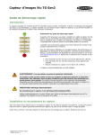


![iVu Plus BCR Gen2 Instruction Manual (Online Only) [ 179047 ]](http://vs1.manualzilla.com/store/data/005859145_1-6c6bbc2cdc90a8f85e92b64ee4999fc2-150x150.png)