1
iVu Barcode Reader (BCR) User's Manual
Rev. A 1/25/2012
Contents
Contents
1 Product Support and Maintenance
.......................................................................................................4
1.1 Product Support .............................................................................................................................................................4
1.2 Maintenance ..................................................................................................................................................................5
2 Overview of the Sensor
.........................................................................................................................6
2.1 Installation ......................................................................................................................................................................6
2.1.1 Components .......................................................................................................................................................6
2.1.2 Cable Connections .............................................................................................................................................9
2.1.3 Installing and Connecting the Sensor
.............................................................................................................14
2.2 Live Mode Overview ....................................................................................................................................................16
2.2.1 Read/No Read, Pass/Fail, Match/No Match ....................................................................................................17
2.2.2 Trigger Modes ..................................................................................................................................................17
2.2.3 Compare Data ..................................................................................................................................................17
2.2.4 Output 1 and Output 2
....................................................................................................................................17
2.2.5 Remote Teach .................................................................................................................................................18
2.3 iVu Emulator ................................................................................................................................................................18
3 Main Menu Reference
..........................................................................................................................19
3.1 Main Menu ...................................................................................................................................................................19
3.2 System Menu ...............................................................................................................................................................20
3.2.1 Sensor Mode ....................................................................................................................................................21
3.2.2 Sensor Configuration .......................................................................................................................................21
3.2.3 Sensor Information ...........................................................................................................................................22
3.2.4 Lock Sensor .....................................................................................................................................................23
3.2.5 Communications Menu ....................................................................................................................................23
3.2.6 Discrete I/O ......................................................................................................................................................27
3.2.7 Display Settings ...............................................................................................................................................29
3.2.8 Reboot Sensor .................................................................................................................................................30
3.2.9 Firmware Update .............................................................................................................................................30
3.3 Imager Menu ................................................................................................................................................................31
3.3.1 Auto Exposure .................................................................................................................................................31
3.3.2 Exposure ..........................................................................................................................................................31
3.3.3 Gain .................................................................................................................................................................32
3.3.4 Trigger ..............................................................................................................................................................32
3.3.5 Focus ...............................................................................................................................................................33
3.3.6 Strobe ..............................................................................................................................................................34
3.3.7 FOV ..................................................................................................................................................................35
3.4 Inspection Menu ..........................................................................................................................................................36
3.4.1 Barcode Menu ..................................................................................................................................................36
3.5 Logs Menu ...................................................................................................................................................................41
3.5.1 Inspection Logs ................................................................................................................................................42
3.5.2 System Logs ....................................................................................................................................................44
3.5.3 Communication Logs .......................................................................................................................................44
4 Display Modes
......................................................................................................................................45
4.1 Display/Hide Annotations .............................................................................................................................................45
4.1.1 Inspection Statistics .........................................................................................................................................46
4.1.2 Inspection Results ............................................................................................................................................46
4.1.3 Barcode Viewer ................................................................................................................................................47
5 Setting up for an Inspection
................................................................................................................48
5.1 Acquiring a Good Image ..............................................................................................................................................48
5.2 Setting Up a Barcode Application ................................................................................................................................51
5.3 Setting up for Data Compare .......................................................................................................................................52
2
Rev. A
Contents
6 iVu BCR Command Channel
...............................................................................................................55
6.1 Command Channel ......................................................................................................................................................55
6.2 Setting Up Serial Communications ..............................................................................................................................56
6.3 Testing and Troubleshooting iVu Command Channel Communications .....................................................................58
6.3.1 Using the Port Status Screen for Testing RS-232 Communications ................................................................58
6.3.2 Understanding the Communication Log ...........................................................................................................59
6.3.3 Using the iVu Command Channel Sample Application or a Terminal Program for Testing .............................60
6.3.4 Verifying Basic Receive Functionality ..............................................................................................................60
6.3.5 Verifying Basic Transmit Functionality .............................................................................................................61
6.4 Command Channel Commands ..................................................................................................................................62
6.4.1 Command Flow
...............................................................................................................................................63
6.4.2 String Delimiters and Escaping ........................................................................................................................63
6.4.3 Command Channel Command Synopsis .........................................................................................................63
6.5 Conventions Used for Examples .................................................................................................................................66
6.6 Examples .....................................................................................................................................................................67
6.6.1 Example 1: How to Trigger the Sensor and Retrieve Barcode Data using the Command Channel ................67
6.6.2 Example 2: How to Modify Barcode Compare Data Using the Command Channel ........................................67
6.7 iVu Command Channel Reference ..............................................................................................................................68
6.7.1 BCR_INPUT Command Group ........................................................................................................................68
6.7.2 BCR_RESULT Command Group .....................................................................................................................68
6.7.3 History Command Group .................................................................................................................................69
6.7.4 Info Command Group ......................................................................................................................................69
6.7.5 Inspection Command Group ............................................................................................................................70
6.7.6 Status Command Group ..................................................................................................................................71
6.7.7 System Command Group ................................................................................................................................71
6.7.8 Teach Command .............................................................................................................................................71
6.7.9 Trigger Command Group .................................................................................................................................72
6.7.10 Command Channel Error Codes ....................................................................................................................72
7 iVu Series: Updating the Sensor
........................................................................................................75
7.1 Update Process ...........................................................................................................................................................75
7.2 How to Set or Modify a Sensor Name .........................................................................................................................75
7.3 How to Reset the Sensor Password ............................................................................................................................76
7.4 How to Use Bitmap Image Files with the iVu Emulator ...............................................................................................77
8 LED Indicator Troubleshooting
..........................................................................................................78
8.1 Errors ...........................................................................................................................................................................78
8.2 Warnings ......................................................................................................................................................................78
3
iVu Barcode Reader (BCR) User's Manual
1 Product Support and Maintenance
This section provides general Banner resources and specific documentation for installers and operators of this iVu BCR Vision Sensor.
WARNING: Not To Be Used for Personnel Protection
Never use this product as a sensing device for personnel protection. Doing so could lead to serious injury or death. This product does NOT include the self-checking redundant circuitry necessary to
allow its use in personnel safety applications. A sensor failure or malfunction can cause either an energized or de-energized sensor output condition.
1.1 Product Support
Banner provides the following resources for quickly setting up and operating the sensor.
Documentation
Online Help
When setting up or monitoring inspections using the iVu sensor's integrated display, you can get online help on any screen by clicking the
Help icon in the upper-right of the screen.
PDF Documentation
The iVu Series Image Sensor documentation is available in a convenient printable format (PDF) on the installation CD or on the Banner
Web site (http://www.bannerengineering.com)
Banner Website
The most current iVu Series sensor information is available on the Banner website:
www.bannerengineering.com
Warranty Service
The iVu Image Sensor is designed for reliability. Do not open the housing; it contains no field-replaceable components. If repair is necessary, do not attempt to repair the sensor yourself; return the unit to the factory. Should it become necessary to return a sensor to the
factory, please do the following:
1. Contact the Banner Factory Application Engineering group at the address or numbers listed below. They will attempt to troubleshoot the system from your description of the problem. If they conclude that a component is defective, they will issue an RMA
(Return Merchandise Authorization) number for your paperwork and give you the proper shipping address.
2. Pack the sensor carefully. Damage which occurs during return shipping is not covered by warranty.
4
www.bannerengineering.com - tel: 763-544-3164
Rev. A
iVu Barcode Reader (BCR) User's Manual
Factory Support
Call, e-mail, fax, or write your local Banner representative or a Banner Applications Engineer for support. Applications Engineers are
available from 8:00 A.M. to 5:00 P.M. Central Time, Monday through Friday, excluding holidays.
Phone
Local: 763.544.3164
Toll Free: 1.888.3.SENSOR (1.888.373.6767)
Fax
763.544.3213
E-mail
[email protected]
Address
Banner Engineering Corp.
9714 10th Avenue North, Minneapolis, MN 55441 USA
To help Banner better assist you, be ready to provide the following information:
•
•
•
•
•
•
iVu firmware version (to find the version number, click Main Menu > System > Sensor Information
Sensor Model Number and Date Code, which are found on the bottom of the sensor.
Exact wording of any messages that appeared on your screen
A description of what you were doing and what happened
A description of how you tried to solve the problem
Error Codes (see LED Indicator Troubleshooting on page 78 )
1.2 Maintenance
Maintenance tasks include keeping the hardware free of dust and dirt and possibly updating the iVu firmware as new versions become
available.
Cleaning the Sensor
Regularly remove any dust or dirt from the Sensor using a soft cloth. If needed, slightly dampen the cloth with a weak solution of neutral
detergent. Avoid getting dirt on the imager (the area behind the lens). If the imager is dirty, use anti-static compressed air to blow off the
dust.
Updating the iVu Firmware
The current version of iVu firmware is available for download from the Banner website. See the Banner Website for the firmware download link.
Rev. A
www.bannerengineering.com - tel: 763-544-3164
5
iVu Barcode Reader (BCR) User's Manual
2 Overview of the Sensor
The iVu BCR sensor reads a wide variety of barcodes. The package consists of lighting, sensor, lens, and display. Appropriate cables
and mounting brackets can be ordered for each application. Additionally, other lenses, brackets, filters and external lights are available.
Installation, setup, and configuration can be done quickly without requiring a PC to configure the sensor.
•
•
•
•
•
No external PC required to configure the sensor
USB 2.0 compliant host provided for easy updating and diagnotistics
Image processing expertise is not required
Integrated or remote color touch screen display
High speed processing
iVu BCR reads the following barcode types:
• DataMatrix (ECC 200) barcodes
• Linear barcodes
•
•
•
•
•
•
•
•
•
•
Code128
Code39
CODABAR
Interleaved 2 of 5
EAN13
EAN8
UPCE
Postnet
IMB
Pharmacode
2.1 Installation
2.1.1 Components
iVu with Integrated Display
The iVu Series sensor comes fully assembled with the lens and an integrated ring light if so ordered. The integrated touchscreen display
has a plastic cover to protect the display. You will need to remove this cover when setting up the sensor. When the display is not in use
be sure to keep the display covered to protect it.
If not using an integrated ring light, you will need to have another lighting source. Various lights are available from Banner.
6
www.bannerengineering.com - tel: 763-544-3164
Rev. A
iVu Barcode Reader (BCR) User's Manual
Rev. A
1
Focusing Window
2
Focusing Window Locking Clip
3
LED - Green: Power; Red: Error
4
LED - Green: Pass; Red: Fail
5
Integrated Display
www.bannerengineering.com - tel: 763-544-3164
7
iVu Barcode Reader (BCR) User's Manual
A
8-pin Euro-style (M12) female USB Cable Connector
B
I/O Cable Connector
C
12 -pin Euro-style (M12) male Power and I/O Cable Connector
C
A
B
Mounting Bracket Mounting Holes (uses supplied three M4 x 4 mm screws)
iVu with Remote Display
The iVu sensor for use with a Remote Display comes fully assembled with the lens and an integrated ring light if so ordered. Although the
Remote Display is not required for normal sensor operation, you will need it to set up the sensor and when you want to monitor inspections.
NOTE: If not using an integrated ring light, you will need to have another lighting source. Various lights are
available from Banner.
8
1
Focusing Window
2
Focusing Window Locking Clip
3
LED - Green: Power; Red: Error
4
LED - Green: Pass; Red: Fail
www.bannerengineering.com - tel: 763-544-3164
Rev. A
iVu Barcode Reader (BCR) User's Manual
A
8-pin Euro-Style (M12) female Remote Display connector
B
12-pin Euro-style (M12) male Power and I/O Cable Connector
C
4-pin Pico (M8) female connector
D
I/O Cable Connector
B
A
C
D
Mounting Bracket Mounting Holes (uses supplied three M4 x 4 mm
screws)
2.1.2 Cable Connections
Cable Connections for iVu BCR with Integrated Display
The power and I/O cable for the iVu BCR sensor is available in 2, 5, 9, and 15 m (6, 15, 30, 50') lengths. The connector on the sensor is
shown below (B).
Power I/O Connections
Pin #
B
Rev. A
Wire Color
Description
Direction
2
Brown
10-30V dc
Input
7
Blue
Common (Signal Ground)
Input
6
Pink
External Trigger
Input
5
Gray
Remote Teach
Input
1
White
Output 1
Output
8
Red
Ready
Output
4
Yellow
Strobe Out (5V dc only)
Output
3
Green
Output 2
Output
9
Orange
Not used
N/A
10
Light Blue
RS-232 TX
Output
11
Black
RS-232 Signal Ground
Output
www.bannerengineering.com - tel: 763-544-3164
9
iVu Barcode Reader (BCR) User's Manual
Power I/O Connections
Pin #
12
Wire Color
Description
Direction
Violet
RS-232 Rx
Input
NOTE: Microlens model shown, C-Mount model connections are identical.
Cable Connections for the iVu BCR with a Remote Display
The cable connections on the iVu sensor are shown below, and power I/O connections (B) are defined in the Power I/O Connections
table below.
A
Remote Display Connector
B
Power I/O Connector
C
USB Connector
B
A
C
NOTE: Microlens model shown, C-Mount model connections are identical.
10
www.bannerengineering.com - tel: 763-544-3164
Rev. A
iVu Barcode Reader (BCR) User's Manual
Power I/O Connections
Pin #
Wire Color
Description
Direction
2
Brown
10-30V dc
Input
7
Blue
Common (Signal Ground)
Input
6
Pink
External Trigger
Input
5
Gray
Remote Teach
Input
1
White
Output 1
Output
8
Red
Ready
Output
4
Yellow
Strobe Out (5V dc only)
Output
3
Green
Output 2
Output
9
Orange
Not used
N/A
10
Light Blue
RS-232 TX
Output
11
Black
RS-232 Signal Ground
Output
12
Violet
RS-232 Rx
Input
iVu Trigger, Remote Teach, and I/O Waveforms
The iVu has two input signals—Trigger and Remote Teach. The default setting is to detect the Trigger or Remote Teach input on the low
to high transition. This setting can be changed in the Main Menu > System > Discrete I/O > Input Polarity screen on the sensor.
iVu Low-to-High Trigger and Remote Teach Input Waveforms
The iVu Trigger and Remote Teach input waveforms are shown below.
Power up
Wire Color
Function
Pink
Trigger
Gray
Remote
Teach
The sensor triggers from low to high, and Remote Teach behaves electrically like trigger (see above).
iVu High-to-Low Trigger and Remote Teach Input Waveforms
The iVu High-to-Low Trigger and Remote Teach input waveforms are shown below.
Power up
Wire Color
Rev. A
Function
Pink
Trigger
Gray
Remote
Teach
www.bannerengineering.com - tel: 763-544-3164
11
iVu Barcode Reader (BCR) User's Manual
The sensor triggers from high to low, and Remote Teach behaves electrically like trigger.
NOTE: If the device used to trigger or remote teach the iVu BCR is a sinking device (that is, NPN), then there
are two options regarding the use of a pull-up resistor:
Option 1: Put a pull-up resistor, rated approximately 1k ohm, between the sensor's positive (+) voltage and
the sensor's input as shown below.
Sinking
VCC
iVu
Trigger Input
1k ohm
Pullup Resistor
Remote Teach Input
NPN
Option 2: Enable the Input Pullup in the iVu BCR software ( Main Menu > System > Discrete I/O > Input
Pullup ).
12
www.bannerengineering.com - tel: 763-544-3164
Rev. A
iVu Barcode Reader (BCR) User's Manual
iVu Output Waveforms
PNP Outputs
Function
Ready
Outputs 1,2, and 3
(Pass)
(Fail)
(Pass)
(Pass)
(Fail)
(Pass)
(Pass)
(Fail)
(Pass)
(Pass)
(Fail)
(Pass)
(Set as Active Pass)
Outputs 1, 2, and 3
(Set as Active Fail)
Strobe Out
(Configure as External
& Expose Based)
NPN Outputs
Function
Ready
Outputs 1, 2, and 3
(Set as Active Pass)
Outputs 1, 2, and 3
(Set as Active Fail)
Strobe Out
(Configure as External
& Expose Based)
Rev. A
www.bannerengineering.com - tel: 763-544-3164
13
iVu Barcode Reader (BCR) User's Manual
2.1.3 Installing and Connecting the Sensor
The iVu BCR sensor requires a bracket for mounting. Three brackets are available from
Banner. The brackets allow the sensor to be mounted either perpendicular to the part or at
an adjustable angle.
Available iVu Brackets
SMBIVURAL
SMBIVURAR
SMBIVUU
Thread three M4 x 4mm screws through the bracket into the mounting holes in the bottom of the sensor. Tighten all three screws.
14
www.bannerengineering.com - tel: 763-544-3164
Rev. A
iVu Barcode Reader (BCR) User's Manual
Installing Filters on the iVu Series Sensor
NOTE: Failure to follow these instructions can cause damage to your iVu Series sensor.
To install a filter on the iVu Series sensor with Micro Lens, use the illustration as a guide and follow the steps listed below.
A
Lens
B
Focusing Window
C
Locking Clip
D
Locking Screw
E
Filter Cap
F
Filter
1. Use the 1/16" hex key to remove the Focusing Window locking screw (D).
NOTE: The Locking Clip (C) inserts in a groove near the top of the Focusing Window (B). When removing the window, the Locking Clip will be loose. Be careful not to lose the clip while removing the window.
2. Unscrew the Focusing Window by turning it clockwise approximately 5 complete turns or until the Focusing Window disengages
from the light/lens assembly.
NOTE: The light/lens assembly may include an integrated ring light or a blank disk if an integrated ring
light is not used. Be careful that the light/lens assembly does not pull out when removing the Focusing
Window. Give a slight tug on the Focusing Window when you think you've unscrewed it far enough. If
the lens assembly moves with the window, continue to rotate the window clockwise until the lens assembly does not move.
3.
4.
5.
6.
Set the Focusing Window aside. Be careful not to get any debris on the window's O-ring.
If present, remove the protective covering on the filter.
Place the filter into the Filter Cap and press the cap onto the lens.
Once the filter is installed, place the Focusing Window back into the housing while inserting the Locking Clip into the groove as
shown below.
Rev. A
www.bannerengineering.com - tel: 763-544-3164
15
iVu Barcode Reader (BCR) User's Manual
7. Press the Focusing Window onto the housing to make sure that it seats correctly (that is, there is no gap between the window and
housing. Rotate the window counter-clockwise at least two turns.
8. Replace the locking tab screw but do not tighten until you have set up and focused the sensor again.
To install a filter on the iVu Series sensor with C-Mount Lens, use the illustration as a guide and follow the steps listed below.
C-Mount Models
C
E
B
A
C-Mount Lens
B
Lens Enclosure
C
Retainer Ring (optional)
D
Filter (optional)
E
Filter Retainer Ring Tool
NOTE: Filter Kits are available separately.
D
1.
2.
3.
4.
C
A
Remove the Lens Enclosure and Lens.
Install filter behind the retainer ring. Make sure it is fully seated.
Using the provided retainer ring tool, thread the retainer ring into the sensor until it firmly seats the filter.
Replace the Lens and Lens Enclosure on the camera.
CAUTION: Avoid the damage that electrostatic discharget (ESD) can cause to the sensor. Always
use a proven method for preventing electrostatic discharge when installing a lens or attaching a cable.
2.2 Live Mode Overview
16
www.bannerengineering.com - tel: 763-544-3164
Rev. A
iVu Barcode Reader (BCR) User's Manual
The iVu BCR can be configured to evaluate one or more of the supported barcode types and can look for a specific number of barcodes
from 1 to 10. The barcode types are selected on the integrated touch screen by accessing Main Menu > Inspection > Barcode Type .
The barcode count is selected on the touch screen by going to Main Menu > Inspection > Barcode Count .
This section describes some general iVu BCR concepts.
2.2.1 Read/No Read, Pass/Fail, Match/No Match
The following describes what is meant by Read/No Read, Pass/Fail, and Match/No Match:
•
•
•
•
•
•
•
A Read condition occurs when the configured number of barcodes are found in a scan. These barcodes must be error-free.
A No Read condition occurs when the configured number of barcodes are not found in a scan.
If the sensor is configured where Data Compare is disabled, Pass and Fail are the same as Read and No Read.
If the sensor is using the Data Compare feature, Pass indicates that a good barcode was found and the data compared.
If the sensor is using the Data Compare feature, Fail indicates that either no good barcode was found or the data did not compare.
A Match condition occurs when the required number of barcodes are found and the compare is successful.
A No Match condition occurs when the required number of barcodes are found, but the compare is not successful.
2.2.2 Trigger Modes
The iVu BCR has four trigger modes that determine how the sensor captures and processes images:
•
•
•
•
External - Single
Continuous
External - Gated
Command
2.2.3 Compare Data
The iVu BCR has a data compare feature for comparing read barcode data against reference data. Data can be manually entered by
accessing the Main Menu > Inspection > Data Compare > Set Data screen. Data of up to 3200 characters can be entered. Additionally,
the data compare feature provides for masking characters within the data.
There are two other ways to enter compare data:
• Importing the last read data while viewing the Set Data screen. The new data is effective on the first trigger that occurs after this
action.
• Using Remote Teach. When a Remote Teach occurs, the data of the first read barcode is saved as Data Compare input. Inspections
executed on the next trigger will use the new data for comparison with subsequently read barcodes. If the previous input data contained any masked characters, Remote Teach will retain the masked characters only if the new data is of the same length as the
previous input data. If the length does not match, masking is removed.
The sensor tries to compare full length of this string with the data read from the barcode. If not equal, inspection will be marked as Fail.
NOTE: If the sensor reads more than one barcode in the field of view, only the first barcode data that the
sensor reads can be compared.
2.2.4 Output 1 and Output 2
The sensor has two output signals that you can configure for Pass, Fail, Read, No Read, Match, No Match, System Error, and Missed
Trigger. The default settings are Pass for Output 1, Fail for Output 2.
Rev. A
www.bannerengineering.com - tel: 763-544-3164
17
iVu Barcode Reader (BCR) User's Manual
NOTE: For all outputs, the default setting is Latched, which means that the signal is active until the results of
an inspection cause a change in the signal output. If Pulsed is selected, the default pulse width is 50 ms.
2.2.5 Remote Teach
The Remote Teach function is a method of remotely updating compare data while the iVu sensor is running. The sequence of events for
executing a Remote Teach as follows:
1. With the sensor Ready, pulse the Remote Teach line.
2. The sensor recognizes that the Remote Teach line has been pulsed and waits for the next valid trigger.
3. At the next valid trigger, Ready goes inactive (the Green Ready LED shuts OFF), and the sensor acquires a new image.
When a Remote Teach occurs, the data of the first read barcode is saved as Data Compare input. Inspections executed on the next
trigger will use the new data for comparison with subsequently read barcodes. If the previous input data contained any masked characters, Remote Teach will retain the masked characters only if the new data is of the same length as the previous input data. If the length
does not match, masking is removed.
2.3 iVu Emulator
The iVu Emulator is a Windows application that allows you to operate in a Windows environment exactly as you would on the iVu Series
sensor itself. In general, the Emulator is an inspection debugging tool where you can:
1. Import stored inspections and configuration from an iVu sensor.
2. Modify inspection parameters on the emulator.
3. Restore the updated configuration back to the sensor.
18
www.bannerengineering.com - tel: 763-544-3164
Rev. A
3 Main Menu Reference
3.1 Main Menu
The Main Menu has four sections. Select: Inspection to modify inspection settings Imager to run the Auto Exposure routine and to make
adjustments to functions like exposure, gain, and strobe. System to set output signals, communication channel parameters and to manage the device. Logs to configure and view System and Inspection Logs.
Rev. A
www.bannerengineering.com - tel: 763-544-3164
19
iVu Barcode Reader (BCR) User's Manual
Inspection
Barcode Type
Barcode
Barcode Count
Data Compare
Compare
Set Data
Properties
Inspection Name
Inspection ID
Scan Time Limit
System
Sensor Mode
Select
Stored Inspections
Live Mode
Add New
Demo Mode
Startup
Delete
Save to USB
Sensor Configuration
Load from USB
Sensor Information
Reset to Defaults
Lock Sensor
Communications
Set Name / ID
Ethernet I/O
Imager
Serial I/O
Industrial Ethernet
Auto Exposure
Exposure
Connection
Status
Gain
View Logs
Trigger
Connection
Strobe
Focus
CommandChannel
External
Internal
Delimiters
Data Export
Maximize FOV
FOV
Connection
Modify FOV
Data to Export
Output Format
Advanced
Image Export
Connection
Image Type
Advanced
Discrete I/O
Logs
Inspection Logs
View Logs
System Logs
Input Polarity
Communication Logs
Input Pullup
Setup
Industrial Ethernet
View Logs
Output Type
Command Channel
Setup
Output 1
Data Export
Output 2
Image Export
Output 3
Locked Sensor Menus
Display Settings
Fail Hold Time
Reboot Sensor
LCD Timeout
Firmware Update
Touch Calibration
Locked
Inspection Logs
System Logs
Communication Logs
Advanced
Unlock Sensor
3.2 System Menu
The System menu icon is on the Main Menu, and is used to manage the sensor. The System menu provides for selecting Sensor Mode,
updating sensor firmware, backing up and restoring sensor Configuration and other general system-level operations.
Main Menu > System
20
www.bannerengineering.com - tel: 763-544-3164
Rev. A
iVu Barcode Reader (BCR) User's Manual
3.2.1 Sensor Mode
Main Menu > System > Sensor Mode
The sensor has two operating modes:
• Live Mode, which is the normal operating mode where the sensor captures live images, scans, and verifies barcodes
• Demo Mode, where inspections are run on stored images and inspection parameters.
The first time you power up the iVu Series sensor, it starts in Demo Mode. Demo Mode uses stored images and inspection parameters that demonstrate how the sensor is set up without having to worry about focus, lighting, or triggers. In this mode, you can learn
how to make adjustments working with the three sensor types while observing how the adjustments affect the sensor results. To exit
Demo Mode, go to Main Menu > System > Sensor Mode and select Exit Demo Mode. When you exit Demo Mode, the sensor
reboots into its normal operating mode with default settings.
3.2.2 Sensor Configuration
The Sensor Configuration menu provides for:
•
•
•
•
•
Saving sensor Configuration to the USB drive
Restoring sensor Configuration from the USB drive
Setting Scan Time Limit
Resetting the sensor to defaults
Updating sensor firmware
Main Menu > System > Sensor Configuration
Rev. A
www.bannerengineering.com - tel: 763-544-3164
21
iVu Barcode Reader (BCR) User's Manual
Save to USB
The Save to USB screen provides for saving sensor Configuration to a USB flash drive. The saved configuration information can be used
as a backup or as a way to clone configuration information for other sensors.
Main Menu > System > Sensor Configuration > Save to USB
NOTE: On the Emulator, this option is Save Configuration.
Load from USB
The Load from USB screen provides for restoring sensor Configuration from a USB drive. This operation will remove all existing inspections and replace them with inspections contained in the configuration file on the USB.
Main Menu > System > Sensor Configuration > Load from USB
NOTE: On the Emulator, this option is Load Configuration.
Reset to Defaults
Resets all sensor configuration to factory defaults. This operation will remove all existing inspections and replace with factory default.
Main Menu > System > Sensor Configuration > Reset to Defaults
3.2.3 Sensor Information
The Sensor Information screen displays the following sensor information:
• Serial Number
• Firmware Version
• Boot Number
• Up Timer
• Hour Count
• Model Number
• Sensor Name
22
www.bannerengineering.com - tel: 763-544-3164
Rev. A
iVu Barcode Reader (BCR) User's Manual
Main Menu > System > Sensor Information
Click the right-arrow next to the Sensor Name field to display a software keyboard that allows you to change the Sensor Name.
3.2.4 Lock Sensor
This option provides for locking the sensor to prevent accidental modification of settings. When locked, the sensor only provides access
to pass/fail statistics, as well as the ability to view logs and to save them to a USB device. A lock icon in the upper left corner of the
sensor display indicates that the sensor is locked. Note that the sensor can be locked with or without a password. If a password is not
used, unlock the sensor by clicking on the Unlock Device menu. When a password is used, it must be 4 digits entered using the software
keypad. If the password is lost, use the Password Reset Utility software provided in the CD to obtain a Reset Key.
NOTE: This menu option is not available on the Emulator.
Main Menu > System > Lock Sensor
3.2.5 Communications Menu
Main Menu > System > Communications
Rev. A
www.bannerengineering.com - tel: 763-544-3164
23
iVu Barcode Reader (BCR) User's Manual
The Communications menu is used to configure the serial I/O channel. There are three menu options:
•
•
•
•
Serial I/O for configuring the Serial port
Industrial Ethernet settings
Command Channel for enabling or disabling commands to the sensor through Ethernet or Serial channels
Data Export Channel for enabling or disabling the channel for data export only
NOTE: Either Data Export Channel OR Command Channel can be enabled.
Port Settings for Serial I/O
Main Menu > System > Communications > Serial I/O
In the Serial I/O screen you can select values for Baud Rate, Stop Bits and Parity Control.
Command Channel
Main Menu > System > Communications > Command Channel
The iVu command channel is a bi-directional communication protocol that currently supports ASCII via the RS-232 serial interface, and
enables other devices to remotely control the iVu sensor and to access sensor results.
24
www.bannerengineering.com - tel: 763-544-3164
Rev. A
iVu Barcode Reader (BCR) User's Manual
Connection
Main Menu > System > Communications > Command Channel > Connection
The Connection screen is used to enable or disable the Command Channel.
Delimiters
Main Menu > System > Communications > Command Channel > Delimiters
In the Delimiters screen, there are three delimiter options that you can set:
• Field Delimiter, which determines what is used to separate data that the sensor is sending out to a remote device.
• End of Frame, which determines the delimiter used to indicate the end of a frame.
• String Delimiter, which determines what is used to enclose a string field during both input and output operations.
Use the drop-down lists to select the appropriate delimiter. The example at the lower part of the screen displays how the data will look in
the output or input streams.
Data Export Channel
Main Menu > System > Communications > Data Export
When the Data Export Channel is enabled, the sensor will transmit selected inspection data when triggered.
Connection
Main Menu > Communications > Data Export > Connection
Rev. A
www.bannerengineering.com - tel: 763-544-3164
25
iVu Barcode Reader (BCR) User's Manual
The Connection screen is used to enable or disable the Data Export Channel.
Data To Export
Main Menu > System > Communications > Data Export > Data To Export
The options in the Data To Export screen are used to determine what barcode data is exported via the serial port.
Output Format
Main Menu > System > Communications > Data Export > Output Format
In the Output Format screen, use the drop-down lists to select Start and End Strings as well a delimiter. In the field at the bottom of the
screen is an example of how the data will look when it is output.
26
www.bannerengineering.com - tel: 763-544-3164
Rev. A
iVu Barcode Reader (BCR) User's Manual
3.2.6 Discrete I/O
The Discrete I/O options are used to adjust iVu input and output settings.
Main Menu > System > Sensor Configuration > Discrete I/O
Input Polarity
The iVu has two input signals—Trigger and Remote Teach. The operation of these signals is dependent on the Input Polarity setting.
• Low To High - The Trigger and Remote Teach are detected on a low to high transition of the signal.
• High To Low - The Trigger and Remote Teach are detected on a high to low transition of the signal.
The default setting for a PNP sensor is Low To High, and for an NPN sensor it is High To Low. The user can change the setting on the
Input Polarity screen.
Main Menu > System > Sensor Configuration > Input Polarity
Rev. A
www.bannerengineering.com - tel: 763-544-3164
27
iVu Barcode Reader (BCR) User's Manual
Input Pullup
Main Menu > System > Sensor Configuration > Discrete I/O > Input Pullup
The NPN version of the iVu sensor triggers from high to low, and Remote Teach behaves electrically like trigger. If using the NPN version
of the sensor, select Enable.
The PNP version of the iVu sensor triggers from low to high, and Remote Teach behaves electrically like trigger. If using the PNP version
of the sensor, select Disable.
Output 1
Output 1 can be configured for Pass, Fail, Read, No Read, Match, No Match, Missed Trigger, or System Error.
• A Read condition is when the configured number of barcodes are found in a scan. These barcodes must be error-free.
• A No Read condition is when the configured number of barcodes are not found in a scan sequence. This will not occur in Continuous
Scan mode.
• If Data Compare is disabled, Pass and Fail are the same as Read and No Read.
• If the sensor is using Data Compare, Pass indicates that a good barcode was found, and the data compared.
• If the sensor is using Data Compare, Fail indicates that either no good barcode was found, or the data did not compare.
• A Match condition occurs when the required number of barcodes are found and the compare is successful.
• A No Match condition occurs when the required number of barcodes are found, but the compare is not successful.
• A Missed Trigger condition occurs when a trigger is received while sensor is busy inspecting the pervious image. This output signal
will be set to active state. This signal will be reset up on resetting the 'History' on the statistics page.
• A System Error condition occurs when a fatal error is detected on the sensor. This output signal will be set to active state. This signal
can be reset upon resetting the 'History' on the statistics page, or executing a 'ClearSystemError' command through command channel.
The default setting is Pass and Latched for Output 1. If Pulsed is selected, the default Pulse width is 50 ms.
28
www.bannerengineering.com - tel: 763-544-3164
Rev. A
iVu Barcode Reader (BCR) User's Manual
NOTE: For Latched the signal is active until the results of an inspection cause a change in the signal output.
Main Menu > System > Sensor Configuration > Discrete I/O > Output 1
Output2
Output 2 can be configured in a similar fashion to Output 1.
The default setting for Output 2 is Fail and Latched.
3.2.7 Display Settings
The Display Settings menu is for setting the Fail Hold Time, LCD Timeout, doing a Touch Screen Calibration. Display optimization can be
enabled in the Advanced menu option.
Main Menu > System > Display Settings
Fail Hold Time
The Fail Hold Time determines how long a failed image is displayed on the LCD so that you can see what failed. The sensor will continue
to process any triggers and the inspection will continue normally. This time delay is just for the screen. You can set this parameter from 0
to 3600 seconds using the slider at the bottom of the screen.
Rev. A
www.bannerengineering.com - tel: 763-544-3164
29
iVu Barcode Reader (BCR) User's Manual
Main Menu > System > Display Settings > Fail Hold Time
LCD Timeout
The LCD screen dims after a user-selectable period when the device is not being used. Use the arrow keys or slide the bar at the bottom
of the screen to set the LCD screen time out.
NOTE: This screen is not available on the Emulator.
Main Menu > System > Display Settings > LCD Timeout
Touch Calibration
Touchscreen Calibration may be necessary if the software does not correctly respond when an icon on the screen is pressed. The calibration routine aligns the touch screen's coordinates to the display behind it. Be sure to follow the prompts on the screen when executing
the Touchscreen Calibration function.
NOTE: This screen is not available on the Emulator.
Main Menu > System > Display Settings > Touch Calibration
Advanced
The Advanced Display screen allows you to edit the response of the display screen settings. Disabling this function may cause the display and touchscreen to be lethargic when sensor is busy.
Main Menu > System > Display Settings > Advanced
3.2.8 Reboot Sensor
The Reboot Sensor screen allows you to force a reboot of the sensor.
NOTE: This option is not available on the Emulator.
Main Menu > System > Reboot Sensor
3.2.9 Firmware Update
The Firmware Update screen is used to load the latest sensor firmware. The Firmware Update screen lists the firmware versions it finds
in the BANNER\FIRMWARE folder on the USB drive. When you receive a firmware update from Banner Engineering, be sure to put it in
the BANNER\FIRMWARE folder on the USB drive.
30
www.bannerengineering.com - tel: 763-544-3164
Rev. A
iVu Barcode Reader (BCR) User's Manual
NOTE: The Firmware Update menu is not available on the Emulator.
Main Menu > System > Firmware Update
3.3 Imager Menu
The Imager menu icon is on the Main Menu, and lists parameters that affect the characteristics of the captured image.
Main Menu > Imager
3.3.1 Auto Exposure
Auto Exposure optimizes the exposure time and gain for the current lighting conditions. Multiple triggers are required to complete this
function.
NOTE: The Auto Exposure option is not available on the Emulator.
Main Menu > Imager > Auto Exposure
3.3.2 Exposure
Exposure is the amount of time the sensor allows light to energize the imager. Increasing the exposure time by moving the slider to the
right allows more light to energize the imager, which brightens the image.
Main Menu > Imager > Exposure
Rev. A
www.bannerengineering.com - tel: 763-544-3164
31
iVu Barcode Reader (BCR) User's Manual
3.3.3 Gain
Gain is an electronic boost to the image signal. Increasing Gain by using the right arrow key or moving the slider to the right increases
image brightness without increasing exposure time. Note that Gain brightens both the light pixels and dark pixels and may reduce the
image quality.
Main Menu > Imager > Gain
3.3.4 Trigger
Main Menu > Imager > Trigger
A Trigger is a signal that makes the sensor capture a barcode image and decode it. From the drop-down list, select either Continuous
Scan, External - Single, or External - Gated.
External-Single Mode
In External-Single mode, the sensor depends on an external trigger. For each trigger, the sensor captures an image and executes one
scan through the configured barcode types looking for the specified number of barcodes. This trigger mode uses the Scan Time Limit
parameter ( Main Menu > System > Sensor Configuration > Scan Time Limit ) to limit the amount of time the sensor will attempt to
scan for barcodes on an image.
32
www.bannerengineering.com - tel: 763-544-3164
Rev. A
iVu Barcode Reader (BCR) User's Manual
Continuous Mode
In Continuous mode, the sensor uses internal timing to continuously capture images. For each captured image, the sensor scans through
the configured barcode types looking for the specified number of barcodes. If the specified number of barcodes is found, a Read event
occurs. If the specified number of barcodes is not found, the sensor captures another image and repeats the scan. There are two parameters that are used to fine-tune how Continuous Scan mode operates:
• Same Code Reject Time (set at the bottom of Main Menu > Imager > Trigger )—time in seconds that must elapse before the scanner will report a previously scanned symbol again. A different symbol will be read immediately.
• Scan Time Limit ( Main Menu > System > Sensor Configuration > Scan Time Limit )—limits the amount of time the sensor will
attempt to scan for barcodes on an image.
NOTE: A No Read condition will not occur in Continuous mode as another image capture and scan automatically follows.
External-Gated Mode
External-Gated mode is similar to Continuous mode. While an external trigger input signal is active, the sensor continues to capture
images and run barcode scans until a successful Read occurs or the External Trigger input signal becomes inactive. The External Gated mode uses the Scan Time Limit parameter ( Main Menu > System > Sensor Configuration > Scan Time Limit ) to limit the
amount of time the sensor will attempt to decode barcodes on an image.
NOTE: A No Read condition will not occur in External - Gated mode while the external trigger is active.
Command Mode
In Command mode, the sensor will capture images when Trigger commands are received. The sensor wil be receiving trigger commands
through the command channel.
3.3.5 Focus
The Focus Number displayed at the bottom of this screen is used to fine-tune image focus. Loosen the lock on the lens cover, turn the
focus ring on the sensor until the Focus Number peaks (or the image appears sharp), then lock the focus ring.
NOTE: For the Focus Number to work, the sensor must be triggering and the images must be similar over
time.
Main Menu > Imager > Focus
Rev. A
www.bannerengineering.com - tel: 763-544-3164
33
iVu Barcode Reader (BCR) User's Manual
3.3.6 Strobe
The Internal Strobe configures the operation of the integrated ring light. The External Strobe configures the operation of an external light.
Main Menu > Imager > Strobe
External
The External Strobe is a 5V output that can be used for an external light. Setting options are Always ON, Always OFF, or Exposure
Based. If Exposure Based is selected, then the external light is on during the time the sensor is capturing an image.
Main Menu > Imager > Strobe > External
34
www.bannerengineering.com - tel: 763-544-3164
Rev. A
iVu Barcode Reader (BCR) User's Manual
Internal
The Internal Strobe setting configures the operation of the integrated ring light. Setting options are Always ON, Always OFF, or Exposure
Based. If Exposure Based is selected, then the ring light is on during the time the sensor is capturing an image.
Main Menu > Imager > Strobe > Internal
3.3.7 FOV
The field of view (FOV) is the area that the sensor can see at a given working distance. The working distance is the distance from the
sensor's lens cover to the part being inspected. By default, the sensor uses the entire FOV in its operation. The effective FOV can be
reduced in order to speed up the processing time of an inspection, or to decrease background noise.
Main Menu > Imager > FOV
Maximize FOV
If the FOV has been modified and you want to get back to the default quickly, click the Maximize FOV menu option to restore the FOV to
the entire sensor display.
Main Menu > Imager > FOV > Maximize FOV
Rev. A
www.bannerengineering.com - tel: 763-544-3164
35
iVu Barcode Reader (BCR) User's Manual
Modify FOV
Use this option to reduce the size of the FOV.
Main Menu > Imager > FOV > Modify FOV
3.4 Inspection Menu
The Inspection menu icon is located on the Main Menu. The Inspection Menu provides options to set inspection parameters on currently
running inspection and manage stored inspections.
Main Menu > Inspection
3.4.1 Barcode Menu
The Barcode Menu is the location for Barcode Type, Barcode Count, and Data Compare screens.
Main Menu > Inspection > Barcode
Barcode Type
Main Menu > Inspection > Barcode Type
The first time the sensor is powered up, the selection checkboxes for DataMatrix and All Linear barcode types are checked. The best
practice is to check only the barcode type(s) applicable for your particular application. Note that, if All Linear is unchecked, a single linear
barcode type can be selected instead.
36
www.bannerengineering.com - tel: 763-544-3164
Rev. A
iVu Barcode Reader (BCR) User's Manual
DataMatrix Settings
Decoder Mode
The Decoder Mode determines which decode algorithm to use and how imperfections in barcode images are handled. When you select
Fast from the drop-down list, the sensor uses an algorithm that is tailored for speed. The algorithm does NOT correct for barcode image
imperfections. The Fast setting has the best results on high-contrast images that contain high-quality barcodes. When you select Robust,
the sensor uses an algorithm that performs routines to correct for imperfections of the barcode image.
Dotpeened
Enabling Dotpeened causes the decoder to be run in a method that is optimized for dot peened data matrix barcodes.
All Linear Settings
The All Linear settings described below apply to the following barcode types:
•
•
•
•
•
•
•
•
Code 128
Code 39
CODABAR
Interleaved 2 of 5
EAN13
EAN8
UPCE
Postnet
Rev. A
www.bannerengineering.com - tel: 763-544-3164
37
iVu Barcode Reader (BCR) User's Manual
• IMB
Checksum Verify
When checksum is enabled, the sensor uses a checksum to verify the integrity of the barcode being read.
Relaxed Quietzone
The Quietzone is a blank margin on either side of a barcode that indicates where the barcode begins and ends. If this Quietzone isn't big
enough, the sensor can have trouble decoding the barcode. By enabling Relaxed Quietzone there is a greater tolerance with respect to
the quiet zone required before and after the barcode.
Pharmacode Settings
Scan Direction
For Pharmacode, you can select one of the following for Line Scanning:
•
•
•
•
•
Left to Right
Right to Left
Top to Bottom
Bottom to Top
Omnidirectional
Use Omnidirectional scanning if barcode can appear inverted on part being inspected. If 'Compare' is enabled, the sensor attempts to
compare that string to decoed data in both scan directions. Inspection is marked as PASS if at least one string matches. The data that
successfully matched is displayed on the screen and is exported through communication channels as requested.
38
www.bannerengineering.com - tel: 763-544-3164
Rev. A
iVu Barcode Reader (BCR) User's Manual
If Omnidirectional scan is selected, but 'Compare' is disabled, the data decoded from left-to-right scan will be reported.
Relaxed Quietzone
The Quietzone is a blank margin on either side of a barcode that indicates where the barcode begins and ends. If this Quietzone isn't big
enough, the sensor can have trouble decoding the barcode. By enabling Relaxed Quietzone there is a greater tolerance with respect to
the quiet zone required before and after the barcode.
Barcode Count
Main Menu > Inspection > Barcode Count
In the Barcode Count screen, select the number of barcodes you want to decode. You can select from 1 to 10.
NOTE: For IMB, Postnet and Pharmacode barcode types, the sensor will decode only one barcode for each of
these types regardless of the Barcode Count setting. This means that if there is one of each of these types in
an image, and the Barcode Count is set to 3, the sensor will decode all three; however, if there are three IMB
barcodes, for example, the sensor will always only decode one IMB barcode.
Data Compare
Main Menu > Inspection > Data Compare
The menu options here are used to set up the sensor for Data Compare. Note that, if the Barcode Count is greater than 1, only the first
barcode data can be compared or used in a remote teach operation. To see which barcode is the first one, turn on annotations.
Rev. A
www.bannerengineering.com - tel: 763-544-3164
39
iVu Barcode Reader (BCR) User's Manual
Compare
Use this menu to enable or disable Data Compare. If Data Compare is enabled, data can be defined in the Compare Data screen. The
data can be retrieved from a previously scanned barcode, or it can be entered using the software keyboard on the touch screen, and
insignificant characters can be masked within the data.
Compare Data
The Compare Data screen allows you to specify data against which you can compare a read barcode. Note that, if the Barcode Count is
greater than 1, only the first barcode data can be compared or used in a remote teach operation. To see which barcode is the first one,
turn on annotations.
• Click the Show last read data button to use the last read barcode data for the data compare.
• Click the Edit button to enter data using a software keyboard on the touch screen.
• Click the Mask button to select characters in the data to mask from the data compare. To mask a character, use the arrows at the
bottom of the screen to move the cursor ([). When the cursor is to the left of a character you want to mask, click the Mask button. The
character will change to green with a slash through it. If you want to unmask a character, make sure that the cursor is to the left of the
masked character, and click the Unmask button.
Edit Compare Data
The Edit screen displays data that was previously read or entered in the text field. The Position of the cursor within the characters displayed ([) in the text field is indicated at the top of the screen. Additionally, the number of characters is indicated by Length. Use the left
and right arrows below the software keyboard to move the cursor between the displayed characters. Place the cursor to the right of any
40
www.bannerengineering.com - tel: 763-544-3164
Rev. A
iVu Barcode Reader (BCR) User's Manual
character and use the back-arrow at the top of the screen to delete that character. Use the button at the bottom right of the screen to
cycle through different character entry keyboards: text entry (with a button to toggle between upper- and lower-case characters), numeric
entry, special character entry, and hex character entry.
Last Read Data
Click the Show last read data button to use the last read barcode data for the data compare
Mask Data
To mask characters in the data, move the cursor to the left of the character(s) to be masked, and click the Mask button. A masked
character will appear gray with a strikeout (\) indicator. To unmask a previously masked character, click the UnMask button. Note that,
when using Remote Teach to set new barcode data, if the previous input data contained any masked characters, Remote Teach will
retain the masked characters only if the new data is of the same length as the previous input data. If the length does not match, masking
is removed.
3.5 Logs Menu
The Logs menu icon is on the Main Menu, and is used to set up, view, and save Inspection and System Logs.
Rev. A
www.bannerengineering.com - tel: 763-544-3164
41
iVu Barcode Reader (BCR) User's Manual
Main Menu > Logs
3.5.1 Inspection Logs
This menu provides for configuring and viewing Inspection Logs. Inspection Logs are stored inspection records that include a captured
image, the parameters used to inspect it, and the results of that inspection. Up to ten Inspection Logs can be held in memory on the
sensor. The next ten overwrite the previous. Inspection Logs can be saved to the USB drive so that the logs can be imported to the
emulator.
Main Menu > Logs > Inspection Logs
View Logs
Inspection Logs appear as a strip of film. You can select a frame to view a specific image. Use the icon in the lower right of the screen to
save the logs to the USB drive. Logs saved to the USB drive can be imported into the emulator. Click the Clear button to clear Inspection
Logs.
Main Menu > Logs > Inspection Logs > View Logs
42
www.bannerengineering.com - tel: 763-544-3164
Rev. A
iVu Barcode Reader (BCR) User's Manual
The View Inspection Log screen is used to debug an inspection, and shows one inspection in read-only mode. Click the upper-left icon
to cycle through views. When in Statistics view, the table title has arrows to switch between Inputs and Results of the Inspection.
Use the left and right arrow keys at the bottom of the screen to navigate through the all stored Inspection Logs.
Setup
Use the radio buttons to Disable Logging, or to log Passed Inspections, Failed Inspections, or All Inspections.
Main Menu > Logs > Inspection Logs > Setup
Rev. A
www.bannerengineering.com - tel: 763-544-3164
43
iVu Barcode Reader (BCR) User's Manual
3.5.2 System Logs
The System Log contains configuration change information, other notifications, and any errors or warnings that may be encountered.
• Click the icon in the upper left corner of the screen to show/hide the time column.
• Click Clear Log button at the bottom of the screen to clear the System Log.
• Click the icon at the lower-right of the screen to save the System Log to the USB drive.
NOTE: System log will not log changes while in Demo mode. Additionally, the Emulator does not log changes.
Main Menu > Logs > System Logs
3.5.3 Communication Logs
The Communication Log contains logs for the two communications channels; Command Channel and Data Export. The features below
are available for each of the logs:
• Click the icon in the upper left corner of the screen to show/hide the time column.
• Click Clear Log button at the bottom of the screen to clear the log.
• Click the icon at the lower-right of the screen to save the Log to the USB drive.
NOTE: Communication log will not log changes while in Demo mode. Additionally, the Emulator does not log
changes.
Main Menu > Logs > Communication Logs
44
www.bannerengineering.com - tel: 763-544-3164
Rev. A
4 Display Modes
In the upper left of the screen is an icon for accessing different Display Modes:
• Display Annotations
• Hide Annotations
• Display Statistics.
4.1 Display/Hide Annotations
Click the icon in the upper-left of the screen to display annotations. When annotations are on, the display shows the data the sensor has
read.
If the sensor reads more than one barcode in the field of view (FOV), in addition to the read data, the display indicates the index of each
read barcode. In the example below, the top barcode is 1 and the bottom barcode is 2. It is important to note that, if the sensor reads
more than one barcode, only the first barcode data (index #1) can be compared or used in a remote teach operation
Click the icon in the upper-left of the screen to hide annotations.
Rev. A
www.bannerengineering.com - tel: 763-544-3164
45
iVu Barcode Reader (BCR) User's Manual
4.1.1 Inspection Statistics
The History screen shows inspection statistics:
•
•
•
•
•
Count Range - minimum and maximum number of objects observed
Passed - running total of parts that passed inspection
Failed - running total of parts that failed inspection
Missed triggers - running total of missed triggers
Time Range - minimum and maximum inspection times observed
4.1.2 Inspection Results
Click the right-arrow button on the History screen to see Inspection Result. The Inspection Result screen shows the last Frame number,
the Barcode Count, the Inspection Time and read Barcode Data for each barcode.
46
www.bannerengineering.com - tel: 763-544-3164
Rev. A
iVu Barcode Reader (BCR) User's Manual
4.1.3 Barcode Viewer
To view detailed information about a particular barcode, click the arrow next to the Barcode # to access the Barcode Viewer screen.
If Data Compare is disabled, The Barcode Viewer screen shows a single text box indicating the index number of the barcode and the
data the sensor is reading. The data is displayed in yellow.
If Data Compare is enabled and the barcode is the first one, there are two text boxes. The upper one displays the data read from the
barcode, and the lower text box shows the data from the Data Compare screen. The sensor does a position-by-position match and the
characters that match are in yellow and mismatches are in red.
Rev. A
www.bannerengineering.com - tel: 763-544-3164
47
iVu Barcode Reader (BCR) User's Manual
5 Setting up for an Inspection
In order to set up for an inspection, you need to:
1. Acquire a good image.
2. Set up a barcode application
3. Set data compare parameters
5.1 Acquiring a Good Image
The iVu Series sensor needs to capture a good image to ensure that it can read the barcode(s) correctly.
1. Go to Main Menu > Imager > Auto Exposure to run the Auto Exposure routine.
2. Check the lighting.
• Make sure that the lighting is constant and consistent (unchanging over time, no shadows or hot spots).
• Capture the barcode with lighting that optimizes its contrast and separates it from the background. Depending on the target,
this may mean the integral ring light is not the best choice and other Banner lights should be considered.
• Adjust the mounting angle to provide the clearest image of the barcode. The mounting bracket lets you easily position and
adjust the sensor on your line. Typically, a slight angle will help with read robustness.
3. If needed, go to Main Menu > Imager > Auto Exposure to run the Auto Exposure routine a second time or adjust Gain and
Exposure manually:
• Main Menu > Imager > Gain
• Main Menu > Imager > Exposure
48
www.bannerengineering.com - tel: 763-544-3164
Rev. A
iVu Barcode Reader (BCR) User's Manual
Rev. A
www.bannerengineering.com - tel: 763-544-3164
49
iVu Barcode Reader (BCR) User's Manual
4. Go to Main Menu > Imager > Focus to adjust the focus while monitoring the Focus Number:
For Micro-lens Models Only:
1. Use the supplied 1/16" hex key to loosen the Focusing Window locking screw (D), then adjust focus on the iVu Series sensor using
the clear Focusing Window (B).
2. Adjust focus while monitoring the focus number. To ensure the best image, adjust the focus until
the Focus Number peaks.
NOTE: Turning the Focusing Window counter-clockwise focuses on
closer objects, while turning the Focusing Window clockwise focuses
on more distant objects.
3. Once the best image has been acquired, lock the focusing window.
Micro-Lens Models
A
Lens
B
Focusing Window
C
Locking Clip
D
Locking Screw
E
Filter Cap (optional)
F
Filter (optional)
NOTE: Filter Kits are available separately.
50
www.bannerengineering.com - tel: 763-544-3164
Rev. A
iVu Barcode Reader (BCR) User's Manual
For C-Mount Models Only:
1. Remove the Lens Enclosure
2. Adjust focus while monitoring the focus number. To ensure the best image, adjust the focus until the Focus Number peaks.
3. Replace the Lens Enclosure on the camera.
C-Mount Models
C
E
B
A
C-Mount Lens
B
Lens Enclosure
C
Retainer Ring (optional)
D
Filter (optional)
E
Filter Retainer Ring Tool
NOTE: Filter Kits are available separately.
D
C
A
5.2 Setting Up a Barcode Application
This section describes how to set up the iVu BCR sensor.
1. Go to Main Menu > Inspection > Barcode Type to select one or more Barcode Types from the list.
NOTE: To ensure optimal performance, select only the barcode types for your application. For example,
if you use only one of the of the barcode types listed for All Linear, uncheck the box next to All Linear,
and select a radio button next to the desired linear barcode type. If you use only DataMatrix, uncheck all
the boxes except the one next to DataMatrix.
2. Go to Main Menu > Inspection > Barcode Count to select the number of barcodes (1 to 10) to be read at one time.
Rev. A
www.bannerengineering.com - tel: 763-544-3164
51
iVu Barcode Reader (BCR) User's Manual
Once the sensor has been set up as described:
• Each successfully read barcode is marked by a green bounding box. If annotations are on, the barcode data is also displayed.
• Any case where data does not compare is marked with a solid red bounding box. If the barcode is marked with a dotted red bounding
box, this indicates a checksum error or quiet zone violation.
• Any barcodes in the field of view that the sensor does not detect (for example, because they are not one of the barcode types selected), are unmarked.
5.3 Setting up for Data Compare
This section describes how to set up the iVu BCR sensor to compare decoded barcode data against some reference. For this example,
the reference data will be from a previously decoded barcode.
1. Go to the Main Menu > Inspection > Data Compare > Compare to Enable data compare.
2. Go to the Main Menu > Inspection > Data Compare > Set Data , and click the Show last read data button.
52
www.bannerengineering.com - tel: 763-544-3164
Rev. A
iVu Barcode Reader (BCR) User's Manual
3. Press the Yes button.
4. Press the Home icon to return to the main screen.
For all subsequent triggers, when the sensor reads the barcode data, it will compare it against this reference data.
Rev. A
www.bannerengineering.com - tel: 763-544-3164
53
iVu Barcode Reader (BCR) User's Manual
54
www.bannerengineering.com - tel: 763-544-3164
Rev. A
6 iVu BCR Command Channel
6.1 Command Channel
The iVu BCR command channel is a bi-directional communication protocol that currently supports ASCII via either Ethernet or the
RS-232 serial interface, and enables other devices to remotely control the iVu sensor and access sensor results.
do trigger\x0D\x0A
B
A
OK\x0D\x0A
D
C
A
Control Device, which can be a PLC, PC program, or a terminal
C
Response Frame
B
Request Frame
D
iVu Plus Sensor
The following are some of the functionality available via the command channel:
•
•
•
•
Get sensor information (such as version and sensor name)
Control "discrete" I/O (such as trigger and teach)
Get sensor results (such as sensor status)
Change the running inspection
6.1 Command Channel Sample Application
The iVu BCR installation CD has a Command Channel sample application that provides an easy interface to execute commands. In a
production environment, you will need to create your own application for bi-directional communication with the sensor.
Rev. A
www.bannerengineering.com - tel: 763-544-3164
55
iVu Barcode Reader (BCR) User's Manual
6.2 Setting Up Serial Communications
The general flow for setting up for serial communications:
1. Prepare the connection — RS-232 wiring.
Electrically connect the control device and the iVu sensor. On the iVu, the pins/wire colors used for serial communications via
RS-232 are shown in the table below.
iVu RS-232 Connections
Pin #
Wire Color
Description
10
Light-Blue
TX
11
Black
Signal Ground
12
Violet
RX
2. Enable the command channel. Go to Main Menu > System > Communications > Command Channel > Connection .
56
www.bannerengineering.com - tel: 763-544-3164
Rev. A
iVu Barcode Reader (BCR) User's Manual
3. Configure port settings (baud rate, data bits, parity, and stop bits) on the iVu to match the settings on the control device. Go to
Main Menu > System > Communications > Serial I/O .
4. Configure end-of-frame delimiters. Go to Main Menu > System > Communications > Command Channel > Delimiters .
Rev. A
www.bannerengineering.com - tel: 763-544-3164
57
iVu Barcode Reader (BCR) User's Manual
Valid end-of-frame delimiters are: <comma>, <colon>, <semicolon>, <CR>, <CR><LF>, <LF><CR>, or <ETX>.
5. Optionally, if you want to trigger the iVu from the control device, set the trigger mode to Command (go to Main Menu > Imager >
Trigger and select Command from the drop-down).
6. Verify that the iVu receives and transmits data correctly.
6.3 Testing and Troubleshooting iVu Command Channel Communications
6.3.1 Using the Port Status Screen for Testing RS-232 Communications
The Port Status screen can be used to ensure data is entering and exiting the sensor. This can be useful for debugging issues such as
improper wiring, mismatched baud rates, or other serial I/O issues. To access the Port Status screen, go to Main Menu > System >
Communications > Serial I/O and click on the Status button.
• The upper field shows the bytes received (request frame) on the iVu from the control device.
• The lower field shows the bytes sent (response frame) from the iVu to the control device.
58
www.bannerengineering.com - tel: 763-544-3164
Rev. A
iVu Barcode Reader (BCR) User's Manual
Port Errors
The Port Errors screen can help to debug communications channel issues: Parity, Break, and Framing indicate mismatched port settings
or, in the case of Break, incorrect cabling.
6.3.2 Understanding the Communication Log
The Communication Log can be used to ensure commands are properly formed (syntax is correct), and provides a history of commands
issued along with responses to these commands. To access the Communication log, go to Main Menu > Logs > Communication Log .
The iVu Plus sensor includes the following Communication Logs:
• Command Channel Log that can be used to ensure that commands are properly formed (syntax is correct), and provides a history of
commands issued along with responses to these commands. To access the Command Channel Log, go to Main Menu > Logs >
Communication Logs > Command Channel .
• Data Export and Image Output logs that are purely output logs (that is, there is no receive activity to log).
Some notes about the logs:
Rev. A
www.bannerengineering.com - tel: 763-544-3164
59
iVu Barcode Reader (BCR) User's Manual
• To see an expanded view of each entry, click on the small right-triangle control on each entry.
• To save the log, click the save icon. The saved communication log can be loaded into the emulator for troubleshooting offline.
The table below describes the icons used in the Communication Log, the up-arrow indicates an incoming request to the iVu from the
control device; the down-arrow indicates an outgoing response from the iVu to the control device.
Icon
Description
Port opened.
Port closed.
Indicates that the command has been processed without errors.
Indicates that the incoming entry is stalled (no new bytes), or end-of-frame delimiter was not received, or client is not reading data on ethernet.
If the response frame contains an error or is dropped, the log entry icons for the request and the
response frames will be colored red, and the displayed error count will increment by one.
If the command takes a long time to process, the last long entry will change to an hourglass (for
example, during trigger of long inspections).
For Ethernet channels:
• The channel's log will show an Enabled entry that indicates which port is being listened to.
• When a client connects, a log entry is added that indicates which IP address connected.
• When a client closes the connection, a log entry indicates that the channel is no longer being listened to.
6.3.3 Using the iVu Command Channel Sample Application or a Terminal Program for Testing
The easiest way to test that the iVu command channel is correctly receiving and transmitting data is to use either the iVu Command
Channel Sample App (available on the installation CD) or to use a terminal program running on a PC:
If using a terminal program, in the terminal program's configuration:
• Set new-line transmit to <CR><LF> (and set the end-of-frame delimiters on the iVu to match).
• Enable local echo.
• Set the Serial port set up so that the PC port number's baud rate, data, parity, and stop bits match those setup on the iVu.
6.3.4 Verifying Basic Receive Functionality
To verify the iVu can receive request frames from the requesting device:
1. On the iVu Sensor, go to the Main Menu > System > Communications > Serial I/O > Port Status screen.
60
www.bannerengineering.com - tel: 763-544-3164
Rev. A
iVu Barcode Reader (BCR) User's Manual
2. On the requesting device, transmit one or more bytes to the iVu sensor.
• If the data byte values appear correct and the number sent by the requesting device matches the number received by the iVu
sensor, then the transmit/receive functionality is working properly.
• If the connection is incorrect (electrically) or if the baud rate is mismatched, no bytes will appear in the upper field on the Port
Status screen.
• If the connection is correct (electrically), bytes will appear in the upper field of the Port Status screen in the order they were
received.
• If the Port Status: Errors at the bottom of the Port Status screen highlights red, then the connection is correct electrically but
there is likely a settings mismatch between the iVu sensor and the requesting device. Verify the settings on both devices.
• If the bytes appear with no errors but appear incorrect or there are too many or too few, then the port settings (for example,
baud rate) are likely mismatched in a way that does not generate serial hardware errors. Verify the settings on both devices
match exactly.
6.3.5 Verifying Basic Transmit Functionality
The iVu command channel will only send response frames to the requesting device if it receives a valid end-of-frame delimiter from the
requesting device. To verify transmit functionality:
1. Transmit an end-of-frame delimiter sequence from the requesting device to the iVu sensor. For example, in a terminal program,
simply hit Enter.
If a valid end-of-frame delimiter is received, the iVu sensor will immediately transmit a short error message back to the requesting
device (for example, ERROR 10000_COMMAND_MISSING).
2. Verify that the number of bytes sent by the requesting device are the same as the number shown in the lower field of the Port
Status screen on the iVu sensor. Go to the Main Menu > System > Communications > Serial I/O > Port Status screen.
Rev. A
www.bannerengineering.com - tel: 763-544-3164
61
iVu Barcode Reader (BCR) User's Manual
3. If the byte count does not match, re-verify that the settings on both devices match exactly. If no bytes are received, re-check the
wiring.
If the correct response frame is received, then basic electrical and port settings are correct.
6.4 Command Channel Commands
All iVu command channel request command frames use the following syntax:
>> command group item value<EOF>
Notes
<EOF> is the end-of-frame delimiter. See below for a description.
All commands are in ASCII and are case-insensitive
command
An action to be performed on a particular iVu group; for example, get, set, do, login, or logout.
group
Identifies the iVu group that the command should act upon; for example, info, system, trigger, or bcr_input.
item
Further qualifies the action by specifying an item within the identified group; for example, comparedata or status.
value
For set commands, this identifies the data that must be set for the specified group item.
Note: Item is not used with get commands.
<EOF>
Identifies the end-of-frame for the command so that the iVu knows to begin processing. The iVu will return a response
that includes the end-of-frame delimiter. The options for the <EOF> are set in the iVu Serial I/O menu, and are as
follows:
• <comma>
• <colon>
• <semicolon>
62
www.bannerengineering.com - tel: 763-544-3164
Rev. A
iVu Barcode Reader (BCR) User's Manual
•
•
•
•
<CR>
<CR><LF>
<LF><CR>
<ETX>
NOTE: When data is displayed on iVu screens such as the Port Status screen,
printable delimiters are displayed as expected. Non-printable characters, such
as <CR> are displayed in hex notation (\x0D).
6.4.1 Command Flow
The command flow should be such that a new command request should not be issued until the iVu command channel acknowledges the
previous command request.
For example, the following is a series of command requests and responses. The first request sets the trigger mode to command and,
once the sensor responds with an "OK," the next command request is issued to do (or execute) the trigger.
>>
<<
set trigger mode command\x0D\x0A
OK\x0D\x0A
>>
<<
do trigger\x0D\x0A
OK\x0D\x0A
6.4.2 String Delimiters and Escaping
By default setting, all strings used in commands are enclosed in quotation marks (""). All text in quotes is part of the command. Quotes (")
or back-slashes (\) that are part of the string must be escapted with a back-slash. For example:
"abc\"def\"ghi\\jkl"
Set the String Delimiter parameters to 'None' if strings should not be enclosed in quotation marks.
6.4.3 Command Channel Command Synopsis
There are a number of general types of commands to do, set, and get sensor data.
Do Commands
Do commands are actions (methods) to perform on the sensor, such as trigger, reboot, and the like.
Command
Group
Description
Reboot
System
Reboots the sensor. Pre-empts other commands except Save.
Save
System
Saves inspection and configuration parameters. Blocks until finished. Should be used
sparingly.
ClearSystemError
Status
Clears the system error LED and sets the
internal flag to false.
Rev. A
www.bannerengineering.com - tel: 763-544-3164
63
iVu Barcode Reader (BCR) User's Manual
Command
Group
Description
Immediate
Trigger
Initiates a single trigger. The sensor does
not transmit a response unitl the sensor has
completed the action.
Gated
Trigger
Initiates gated triggering. The sensor does
not transmit a response unitl the sensor has
completed the action.
AbortGated
Trigger
Aborts gated triggering. The sensor does
not transmit a response unitl the sensor has
completed the action, then it will respond
with two responses.
NextTrigger
Teach
Sets the sensor to teach on the next trigger
Clear
History
Clears all history fields (for example pass,
fail, etc.).
Get Commands
Get commands are used to retrieve information from the sensor (for example, get the status of the sensor).
Command
Group
Description
CompanyName
Info
The company name as a string.
ModelNumber
Info
The sensor model number as a string.
FirmwareVersion
Info
The sensor firmware version as a string.
SerialNumber
Info
The sensor serial number as a string.
Name
Info
The sensor name as a string.
BootNumber
Info
The number of sensor bootups
UpTimer
Info
The elapsed time the sensor has been running in the format hh:mm:ss:msec.
HourCount
Info
The number of hours the sensor has been
running.
RemoteConnected
Info
The remote display connected status as a
boolean value (true or false)
RemoteModelNumber
Info
The model number of the remote display as
a string.
RemoteSerialNumber
Info
The serial number of the remote display as
a string.
Ready
Status
Flag indicating whether the system is ready
to trigger (true) or busy (false)
SystemError
Status
Flag indicating whether a system error is
active (true) or cleared (false)
Mode
Trigger
Sets trigger mode to one of the valid trigger
modes for the sensor.
Passed
History
The number of passed inspections.
64
www.bannerengineering.com - tel: 763-544-3164
Rev. A
iVu Barcode Reader (BCR) User's Manual
Command
Group
Description
Failed
History
The number of failed inspections.
MissedTriggers
History
The number of missed triggers.
StartFrameNumber
History
The starting frame number.
EndFrameNumber
History
The ending frame number.
MinInspectionTime
History
The minimum elapsed time (msec) of the
inspection.
MaxInspectionTime
History
The maximum elapsed time (msec) of the
inspection.
MinBarcodeCount
History
The minimum number of barcodes read.
MaxBarcodeCount
History
The maximum number of barcodes read.
Status
Inspection
This status of the most recent inspection either Pass, Fail, or Idle (no triggers).
FrameNumber
Inspection
The most recent inspection frame number
ExecutionTime
Inspection
The most recent inspection execution time
in msec.
ReadNoRead
Inspection
The barcode decoder statsus either read or
barcode not found.
CompareData
BCR_INPUT
The compare data string. This string must
start and end with the double quote character.
CompareMask
BCR_INPUT
The compare string mask in binary format;
that is, masked characters are indicated by
a "1" and unmasked characters are "0."
Note that the mask character string must
match the length of the compare string.
Count
BCR_RESULT
The total number of barcodes found in the
last inspection.
Data
BCR_RESULT
The barcode data strings that were read in
the last inspection. Each string starts and
ends with the double quote character. Multiple strings are seperated by the field delimiter
Type
BCR_RESULT
The type(s) of barcodes read in the last inspection. Multiple values are seperated by
the field delimiter.
MaxPercentMatch
MATCH_RESULT
(New Item Please Add Description Here)
Set Commands
Set commands set some group item on the sensor (for example, set compare data for the BCR).
Command
Group
Item
Value
Set
BCR_INPUT
CompareData
<VALUE>
Rev. A
www.bannerengineering.com - tel: 763-544-3164
65
iVu Barcode Reader (BCR) User's Manual
Command
Group
Item
Value
Set
BCR_INPUT
CompareMask
<MASK >
Set
Trigger
Mode
ContinuousScan
Set
Trigger
Mode
ExternalSingle
Set
Trigger
Mode
ExternalGated
Set
Trigger
Mode
Command
Command Channel Response Frames
The iVu responds to all request frames with one or two responses depending on the type of command.
Do commands
All do commands are followed by one response that identifies the command status. For example:
>>
<<
do trigger\x0D\x0A
OK\x0D\x0A
Get commands
All get commands are followed by two responses: the first identifies the status of the command, and the second contains the retrieved information. For example:
>>
<<
<<
get bcr_input comparedata\x0D\x0A
OK\x0D\x0A
"012345ABCDEF"\x0D\x0A
Set commands
All set commands are followed by one response that identifies the command status. For example:
>>
<<
set bcr_input comparedata "012345ABCDEF"\x0D\x0A
OK\x0D\x0A
Command Channel Command Status
The command status is either OK or ERROR. If OK, then the command has fully and successfully completed. If an error is returned it is in
the form ERROR nnnnn_ERROR_IDENTIFIER (for example ERROR 10001_COMMAND_NOT_RECOGNIZED). Refer to Command
Channel Error Codes on page 72 for a list of errors.
6.5 Conventions Used for Examples
There are a number of command channel examples included here, and the following are the conventions used in the examples:
• All examples use <CR><LF> for the end-of-frame delimiter, and this delimiter is always denoted in hex (\x0D\x0A) since that is what
is displayed in the iVu logs and, for example, the Port Status screen.
• All commands are in bold text.
• For each example, a command request to the iVu sensor is prefaced with a >>, and a command response frame from the iVu sensor
is prefaced by a << as shown below. These are only used to make the documentation clearer.
66
www.bannerengineering.com - tel: 763-544-3164
Rev. A
iVu Barcode Reader (BCR) User's Manual
>>
<<
<<
get info companyname\x0D\x0A
OK\x0D\x0A
"Banner Engineering Corp."\x0D\x0A
6.6 Examples
6.6.1 Example 1: How to Trigger the Sensor and Retrieve Barcode Data using the Command Channel
To trigger the sensor and retrieve barcode data, do the following
1. Set Trigger to Command. Go to the Main Menu > Imager > Trigger screen, and from the drop-down select Command
2. Issue a trigger command as follows:
>>
<<
do trigger\x0D\x0A
OK\x0D\x0A
3. Check that the inspection passed.
>>
<<
<<
get inspection status\x0D\x0A
OK\x0D\x0A
Pass\x0D\x0A
4. Get the barcode data read by the iVu sensor.
>>
<<
<<
get bcr_result\x0D\x0A
OK\x0D\x0A
"0043000011201"x0D\x0A
6.6.2 Example 2: How to Modify Barcode Compare Data Using the Command Channel
1. Set Trigger to Command. Go to the Main Menu > Imager > Trigger screen, and from the drop-down select Command
2. Set the compare data.
>>
<<
set bcr_input comparedata "0043000011201"\x0D\x0A
OK\x0D\x0A
3. Trigger the sensor.
>>
<<
do trigger\x0D\x0A
OK\x0D\x0A
4. Check that the inspection passed.
>>
<<
<<
Rev. A
get inspection status\x0D\x0A
OK\x0D\x0A
Pass\x0D\x0A
www.bannerengineering.com - tel: 763-544-3164
67
iVu Barcode Reader (BCR) User's Manual
5. Get the barcode data read by the iVu sensor.
>>
<<
<<
get bcr_result data\x0D\x0A
OK\x0D\x0A
"0043000011201"\x0D\x0A
6.7 iVu Command Channel Reference
6.7.1 BCR_INPUT Command Group
Command
Group
Item
Description
get
bcr_input
comparedata
Returns the compare string.
get
bcr_input
comparemask
Returns the compare string mask. Masked characters are
indicated by a "1" and unmasked characters are "0." Note
that the mask character string must match the length of the
compare string.
set
bcr_input
comparedata
Sets the compare string.
set
bcr_input
comparemask
Sets the compare string mask. Masked characters need indicated by a "1" and unmasked characters are "0, " and the
mask character string must match the length of the compare string.
Examples:
>>
<<
<<
get bcr_input comparedata\x0D\x0A
OK\x0D\x0A
"0043000111201"\x0D\x0A
>>
<<
<<
get bcr_input comparemask\x0D\x0A
OK\x0D\x0A
"1111000000000"\x0D\x0A
>>
<<
set bcr_input comparedata "0043000111201"\x0D\x0A
OK\x0D\x0A
>>
<<
set bcr_input comparemask "1111000000000"\x0D\x0A
OK\x0D\x0A
6.7.2 BCR_RESULT Command Group
Command
Group
Item
Description
get
bcr_result
count
Returns the number of barcodes found
get
bcr_result
data
Returns the barcode data that the iVu sensor read.
get
bcr_result
type
Returns the type of the barcode read. Multiple items are separated by a
field delimiter.
Examples:
68
www.bannerengineering.com - tel: 763-544-3164
Rev. A
iVu Barcode Reader (BCR) User's Manual
>>
<<
<<
get bcr_result count\x0D\x0A
OK\x0D\x0A
1\x0D\x0A
>>
<<
<<
get bcr_result data\x0D\x0A
OK\x0D\x0A
"0043000011201"\x0D\x0A
>>
<<
<<
get bcr_result type\x0D\x0A
OK\x0D\x0A
EAN13\x0D\x0A
6.7.3 History Command Group
Command
Group
Item
Description
get
history
passed
Returns the number of passed inspections.
get
history
failed
Returns the number of failed inspections.
get
history
missedtriggers
Returns the number of missed triggers.
get
history
startframenumber
Returns the start frame number.
get
history
endframenumber
Returns the end frame number.
get
history
mininspectiontime
Returns the minimum elapsed time of the inspection.
get
history
maxinspectiontime
Returns the maximum elapsed time of the inspection.
get
history
minbarcodecount
Returns the minimum number of barcodes read.
get
history
maxbarcodecount
Returns the maximum number of barcodes read .
do
history
clear
Clears all history fields (for example pass, fail, etc.).
Examples:
>>
<<
<<
get history passed\x0D\x0A
OK\x0D\x0A
13\x0D\x0A
>>
<<
<<
get history startframenumber\x0D\x0A
OK\x0D\x0A
3\x0D\x0A
>>
<<
<<
get minbarcodecount\x0D\x0A
OK\x0D\x0A
1\x0D\x0A
>>
<<
do history clear\x0D\x0A
OK\x0D\x0A
6.7.4 Info Command Group
Command
Group
Item
Description
get
info
companyname
Returns the company name.
Rev. A
www.bannerengineering.com - tel: 763-544-3164
69
iVu Barcode Reader (BCR) User's Manual
Command
Group
Item
Description
get
info
modelnumber
Returns the sensor model number.
get
info
firmwareversion
Returns the sensor firmware version.
get
info
serialnumber
Returns the sensor serial number.
get
info
bootnumber
Returns the number of sensor bootups.
get
info
name
Returns the sensor name.
get
info
uptimer
Returns the elapsed time the sensor has been running in the format hh:mm:ss:ms.
get
info
hourcount
Returns the number of hours the sensor has been running.
get
info
remoteconnected
Returns the whether a remote display is connected as a boolean
value (true or false).
get
info
remoteserialnumber
Returns the the serial number of the remote display.
get
info
remotemodelnumber
Returns the model number of the remote display.
Examples:
>>
<<
<<
get info companyname\x0D\x0A
OK\x0D\x0A
"Banner Engineering Corp."\x0D\x0A
>>
<<
<<
get info bootnumber\x0D\x0A
OK\x0D\x0A
42\x0D\x0A
>>
<<
<<
get info uptimer\x0D\x0A
OK\x0D\x0A
4:42:42:324\x0D\x0A
6.7.5 Inspection Command Group
Command
Group
Item
Description
get
inspection
status
Returns either Pass, Fail, or Idle.
get
inspection
readnoread
Returns either Read (found) or NoRead (not found).
get
inspection
framenumber
Returns the frame number.
get
inspection
executiontime
Returns the inspection execution time.
Examples:
>>
<<
<<
get inspection status\x0D\x0A
OK\x0D\x0A
"Fail"\x0D\x0A
>>
<<
<<
get inspection readnoread\x0D\x0A
OK\x0D\x0A
Read\x0D\x0A
>>
get inspection executiontime\x0D\x0A
70
www.bannerengineering.com - tel: 763-544-3164
Rev. A
iVu Barcode Reader (BCR) User's Manual
<<
<<
OK\x0D\x0A
37.739\x0D\x0A
6.7.6 Status Command Group
Command
Group
Item
Description
get
status
ready
Returns either True (ready for trigger) or False.
get
status
systemerror
Returns either True or False.
do
status
clearsystemerror
Resets SystemError to False.
Examples:
>>
<<
<<
get status ready\x0D\x0A
OK\x0D\x0A
True\x0D\x0A
>>
<<
<<
get status systemerror\x0D\x0A
OK\x0D\x0A
False\x0D\x0A
>>
<<
do status clearsystemerror\x0D\x0A
OK\x0D\x0A
6.7.7 System Command Group
Command
Group
Item
Description
do
system
save
Saves inspection and configuration parameters. Blocks until finished. Should be used sparingly.
do
system
reboot
Reboots the sensor. Pre-empts
all commands except save.
>>
<<
do system save\x0D\x0A
OK\x0D\x0A
6.7.8 Teach Command
Sets the sensor to teach on the next trigger
Example:
>>
<<
Rev. A
do teach\x0D\x0A
OK\x0D\x0A
www.bannerengineering.com - tel: 763-544-3164
71
iVu Barcode Reader (BCR) User's Manual
6.7.9 Trigger Command Group
Command
Group
Item
Description
set
trigger
mode
Sets trigger mode to one of the valid trigger modes for the sensor: ContinuousScan, External, ExternalGated, or Command.
get
trigger
mode
Returns the trigger mode.
do
trigger
do
trigger
gated
Initiates gated triggering. The sensor does not transmit a response until the
sensor has completed the action.
do
trigger
abortgated
Aborts gated triggering. The sensor does not transmit a response until the
sensor has completed the action, then it will respond with two responses
(one from the previous gated trigger and one for the abort).
Initiates a single trigger. The sensor does not transmit a response until the
sensor has completed the action.
Examples:
>>
<<
set trigger mode command\x0D\x0A
OK\x0D\x0A
>>
<<
<<
get trigger mode\x0D\x0A
OK\x0D\x0A
Command\x0D\x0A
>>
<<
do trigger\x0D\x0A
OK\x0D\x0A
The following example shows a gated trigger that is taking too long so an do trigger abortgated command is executed.
>>
>>
<<
<<
do trigger gated\x0D\x0A
do trigger abortgated\x0D\x0A
OK\x0D\x0A
OK\x0D\x0A
6.7.10 Command Channel Error Codes
Numeric ID
Text ID
Description
00000
SUCCESS
Command processed successfully
10000
EMPTY_FRAME_RECEIVED
Indicates that the request was empty. The
command channel requires a command,
any arguments, and an end-of-frame delimiter.
10001
COMMAND_NOT_RECOGNIZED
The command specified is not recognized
10100
GROUP_MISSING
A Group ID must be specified immediately
after the command
72
www.bannerengineering.com - tel: 763-544-3164
Rev. A
iVu Barcode Reader (BCR) User's Manual
Numeric ID
Text ID
Description
10101
GROUP_NOT_FOUND
The specified Group ID is invalid / unknown
10102
GROUP_ITEM_MISSING
A Group Item ID must be specified immediately after the Group ID
10103
GROUP_ITEM_NOT_FOUND
The specified Group Item ID is invalid / unknown
10152
NOT_READABLE
Attempt to get a value that is not readable
10153
NOT_WRITEABLE
Attempt to set a value that is not writeable
10250
NOT_A_METHOD
Method ID specified is not a method
10251
WRONG_ARGUMENT_COUNT
Total method arguments specified do not
match method
10252
COMMAND_NOT_FINISHED
Attempt to issue command when a previous
command has not finished
10300
INVALID_ARGUMENT_TYPE
Item ID specified must be a item (not a
group or method)
10301
DATA_VALUE_MISSING
Command missing item's data value
10350
ARGUMENTS_DETECTED
Get command received with unneeded arguments
10351
INVALID_ARGUMENT_TYPE
Item ID specified must be a item (not a
group or method)
10340
MINIMUM_VALUE_EXCEEDED
New item value is below the minimum
10341
MAXIMUM_VALUE_EXCEEDED
New items value is above the maximum
10500
DATA_SET_EMPTY
Data export operation returned no results.
10900
SENSOR_NOT_READY
Command specified requires sensor to be
in the READY state.
10920
SENSOR_TYPE_NOT_ACTIVE
Command specified belongs to a different
sensor type.
15000
VALUE_INVALID
Text value is invalid / unknown
15050
VALUE_INVALID
Text value is invalid - expecting True or
False
15100
STRING_TOO_LONG
String value specified exceeds maximum
allowable length
20000
BARCODE_TIMEOUT
Attempt to obtain Barcode result data when
decoder has timed out
20001
NO_BARCODES_FOUND
Attempt to obtain Barcode result data when
no barcodes were found
20002
COMPARE_DATA_DISABLED
Operation requires Barcode compare to be
enabled
20003
COMPARE_MASK_INVALID
Compare mask invalid. Expecting string of
1's and 0's with length equal to compare
data string
Rev. A
www.bannerengineering.com - tel: 763-544-3164
73
iVu Barcode Reader (BCR) User's Manual
Numeric ID
Text ID
Description
20004
NUMBER_TO_FIND_NOT_ONE
Barcode number to find must be set to one
for this operation.
80000
REMOTE_DISPLAY_NOT_CONNECTED
Remote Display must be connected to obtain this value
80001
REMOTE_DISPLAY_NOT_SUPPORTED
This sensor does not have Remote Display
capability
80100
COMMAND_MODE_EXPECTED
The Trigger Mode must be set to "Command" perform this operation
80101
COMMAND_TIMED_OUT
The command timed out before finishing
80102
TRIGGER_REQUIRED
Access to the specified data requires a triggered inspection
80103
TRIGGER_NOT_GATED
Command requires a active Gated Trigger
80150
COMMAND_TIMED_OUT
The command timed out before finishing
80200
SYSTEM_ERROR_NOT_ACTIVE
The System Error must be active to execute this command
74
www.bannerengineering.com - tel: 763-544-3164
Rev. A
7 iVu Series: Updating the Sensor
7.1 Update Process
Banner Engineering may release new versions of the sensor firmware in the future. New firmware releases can be downloaded from
Banner's website or can be obtained by ordering the latest Product CD. The following steps will guide you through the process of updating the iVu firmware.
Step 1: Copy firmware of desired product to USB Thumb Drive.
1. Launch the iVu Series software
From Product CD:
• Place the latest Product CD into your CD ROM drive. The iVu Series Software will automatically start.
• If your computer is not set for Auto-Play, you may start the iVu Series Software by browsing to the CD drive from My Computer
screen and double-clicking on 'iVuSeries.exe'.
From Banner Website:
•
•
•
•
•
Visit Banner's Website: http://www.bannerengineering.com
Browse to Vision Products page and select the iVu product you are using.
Click on the Software tab to view software releases.
Determine which version you want to download (Current Version recommended, for example "iVu Series Software Version 2010R4").
Click on the circular Download button. This will initiate the download process. Depending on your browser settings, you may be
asked to confirm or provide a location to save the file. Choose to download on yoru desktop. Note the file name.
• Double-click the file to start extracting the files and run the iVu Series Software.
2. Select the product you are using and browse to Firmware Update page.
3. Click on 'Run Firmware Update Wizard' and program will start.
4. Follow on-screen instructions. Clicking on 'Copy firmware to USB' will copy the selected firmware to the USB Thumb Drive.
Step 2: Install firmware on iVu
1. Remove the USB Thumb Drive from the PC, and plug it into the sensor.
2. On the sensor, select System -> Firmware Update. The name of the firmware file you copied on the USB Thumb Drive will be displayed.
3. Choose correct file and click on the 'Load' button.
4. Follow the steps on the screen to update the firmware.
7.2 How to Set or Modify a Sensor Name
You can set a Sensor Name for your iVu Series sensor or modify an existing name on the sensor using the software keypad. You can
also change the sensor name this using the iVu Emulator as described below.
NOTE: If you are in a language other than English, you cannot modify the sensor name using the software
keypad. Use the procedure described below.
Rev. A
www.bannerengineering.com - tel: 763-544-3164
75
iVu Barcode Reader (BCR) User's Manual
NOTE: If you have not set the sensor previously, then folders will be named using the first 8-characters of the
sensor serial number.
1. Plug a USB Thumb Drive into the sensor.
2. Save Sensor Configuration to the USB Thumb Drive ( Main Menu > System > Sensor Configuration > Save to USB ). The
locaton of these files on the USB Thumb Drive will be displayed after the operation is complete—the sensor configuration is saved
in <USB>:\BANNER\<SENSOR_NAME>. For example, if the sensor name is myName:, the path will be <USB>:\BANNER\myName).
3. Remove the USB drive from the sensor and insert it into an available USB drive on a Windows PC.
4. If running the Emulator from the USB, launch the iVuEmulator.exe program. If running the Emulator installed on a PC, make sure
the Emulator is not running, and copy the Sensor Configuration from the USB Thumb Drive to the folder where the Emulator is
installed on the PC. For example, if the sensor name is myName and the iVu Emulator is installed in the default location on the PC,
copy the file <USB>:\BANNER\myName\CONFIG.CFG to C:\Program Files\Banner Engineering\iVu Series.
5. Launch the iVuEmulator.exe program.
6. Go to the Sensor Information screen ( Main Menu > System > Sensor Information ).
7. Click the white box next to the Sensor Name label, and enter the desired Sensor Name.
8. Click the Back button on the lower-left corner of the screen to save the Sensor Name.
9. Close the Emulator program and the Sensor Name will be saved to the CONFIG.CFG file.
10. If running the Emulator on the PC, copy the CONFIG.CFG file back to the original folder on the USB drive—<USB>:\BANNER
\<SENSOR_NAME> (for example <USB>:\BANNER\myName).
NOTE: The sensor will look in the original folder (for example, myName) for the CONFIG.CFG file.
11. Remove the USB Thumb Drive from the PC, and connect to the sensor.
12. Restore the configuration to the sensor.
a. Go to Main Menu > System > Sensor Configuration > Load from USB .
b. Select the Configuration to restore.
c. Click the Load button to start the restore sensor configuration.
NOTE: Once the new sensor name is restored in the sensor, all files saved to USB will now reside
in the folder corresponding to the new sensor name.
You will need to reboot the sensor when the restore is complete.
NOTE: If a Sensor Configuration from one sensor is loaded onto another sensor, the Sensor Name from the
Sensor Configuration will not be stored in the sensor.
7.3 How to Reset the Sensor Password
If you forget the password for your sensor, you can remove the current password using a reset key that is generated by the Password
Reset Utility, which is located on the Product CD. The following steps will guide you through the specific steps to reset the password:
1.
2.
3.
4.
5.
76
On your iVu Series sensor, click the Forgot? button located on the bottom of the Enter Current Password screen.
Write down the 6-digit Device Key.
On a Windows PC, insert the iVu product CD into the CD ROM drive.
From the product CD menu (started upon inserting the CD), launch the Password Reset Utility.
Enter the Device Key into the text box in the Utility—identified as Step 1 in the Password Reset Utility.
www.bannerengineering.com - tel: 763-544-3164
Rev. A
iVu Barcode Reader (BCR) User's Manual
6. Click the Generate Reset Key button.
7. Write down the four-digit Password Reset Key—identified as Step 2 in the Password Reset Utility.
8. On the iVu Series sensor, check the Next button on the Password Reset screen.
9. Enter the 4-digit reset key on the Enter Reset Key screen.
10. Click Apply.
The password is now cleared.
7.4 How to Use Bitmap Image Files with the iVu Emulator
You can use bitmap (.bmp) image files with the iVu Emulator for developing and simulating iVu inspections. The iVu Emulator only accepts image files in .bmp format. If you have other image file formats, use an image viewer/editor program, such as PhotoShop, Gimp, or
Paint, to convert the files to 8-bit grayscale .bmp format.
NOTE: Images smaller than 640 X 480 will be black-filled starting in the upper-right. Images larger than 640 X
480 will be cropped starting in the upper-left.
1. Copy the .bmp files into the InspLog folder in the iVu Emulator install folder.
For example, copy .bmp files into the C:\Program Files\Banner Engineering\iVu Series\InsLog folder.
NOTE: Remove any existing .bmp or Log files in that folder to avoid confusion because the Emulator
automatically runs all .bmp/Log files sequentially according to filename.
2. Launch the iVu Emulator program.
3. Select Internal Trigger on the Trigger Selection screen ( Main Menu > Image > Trigger ) and select Internal.
4. Set the Trigger Interval as desired.
The iVu Emulator will be running using the .bmp files from Step 1.
NOTE: Banner does not recommend setting up inspections using these 8-bit grayscale images because you
will always end up modifying the configuration after loading it on the sensor on the line. A better choice would
be to set up the inspection on the emulator using Inspection Logs from the sensor.
Rev. A
www.bannerengineering.com - tel: 763-544-3164
77
iVu Barcode Reader (BCR) User's Manual
8 LED Indicator Troubleshooting
In normal operation, the Power LED is steady green, and the Pass/Fail is green or red depending on the triggered inspection. The Ethernet I/O LED will be lit or off depeding on connection status.
1
Power LED
Green: Power
Red: Error
2
Pass/Fail LED
Green: Pass
Red: Fail
3
Ethernet I/O LED
Green: Connected
No Light: Disconnected
The iVu also indicates abnormal conditions as described below.
8.1 Errors
Problem Indicator
Solution
The Pass/Fail LED is blinking green a number of
times, separated by an LED red blink, and the sensor repeats this pattern over and over. This indicates that no inspections are occurring.
Reboot the sensor.
The Power LED is lit steady red. These type of errors are reported in the System log and appear
highlighted in red.
Do the following:
1. Look in the System Log to see the error.
2. Clear the LED; that is, go to the Main Menu > Logs > System Logs and
press the Clear System Error button at the bottom of the screen (a sensor
reboot is not required).
3. If the error occurs again, you can try rebooting the sensor to see if that fixes the problem. If the problem persists, contact Banner customer support.
8.2 Warnings
78
www.bannerengineering.com - tel: 763-544-3164
Rev. A
iVu Barcode Reader (BCR) User's Manual
Warnings are atypical conditions that the sensor detects and fixes. Warning are highlighted in yellow in the System Log, and can typically
be ignored.
Rev. A
www.bannerengineering.com - tel: 763-544-3164
79
Index
A
Advanced 30
auto exposure 31
C
command channel log 59
command channel sample application 55
Communication Logs 44
D
data export log 59
Display Settings menu 29
E
exposure 31
external strobe 34
F
fail hold time 29
field of view 35
firmware update 30
focus number 33
G
gain 32
I
imager
auto exposure 31
exposure 31
gain 32
imager menu 31
Inspection Logs 42
inspection menu 36
internal strobe 35
Load from USB 22
lock sensor 23
logs
command channel 59
data export 59
communication 44
inspection 42
system 44
M
menu
Display Settings 29
Sensor Configuration 21
Sensor Mode 21
System 20
S
sample application
command channel 55
Save to USB 22
Sensor Configuration menu 21
Sensor Information 22
Sensor Mode menu 21
serial communications 56
strobe
external 34
internal 35
System Logs 44
System menu 20
T
Touchscreen Calibration 30
U
USB
loading from 22
saving to 22
L
LCD Timeout 30
Warranty: Banner Engineering Corporation warrants its products to be free from defects
for a period of one year. Banner Engineering Corporation will repair or replace, free of
charge, any product of its manufacture found to be defective at the time it is returned to
the factory during the warranty period. This warranty does not cover damage or liability
for the improper application or installation of Banner products. This warranty is in lieu of
any other warranty either expressed or implied.


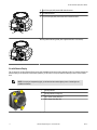
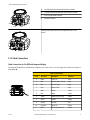


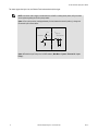
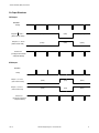

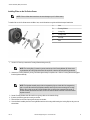
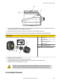


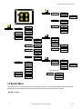
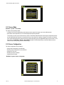


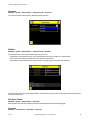


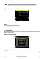


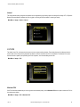


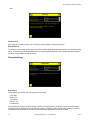


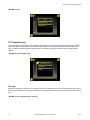


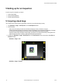


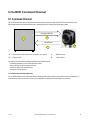


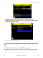
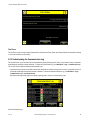
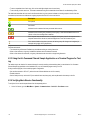

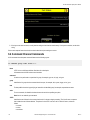

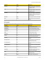


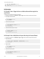


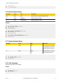

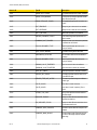


![iVu Plus BCR Quick Start Guide [ 154722 ]](http://vs1.manualzilla.com/store/data/005993547_1-f3116733e8f794d590f924e47d0edfff-150x150.png)

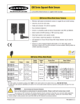

![iVu Plus BCR Gen2 Instruction Manual (Online Only) [ 179047 ]](http://vs1.manualzilla.com/store/data/005859145_1-6c6bbc2cdc90a8f85e92b64ee4999fc2-150x150.png)