1
iVu Plus User's Manual
Online Only - rev. A 1/7/2011
Contents
Contents
1 Product Support and Maintenance
.....................................................................................4
1.1 Product Support ........................................................................................................................................4
1.2 Maintenance .............................................................................................................................................5
2 Overview of the Sensor
........................................................................................................6
2.1 Typical iVu Applications ............................................................................................................................6
2.1.1 Label Inspection ............................................................................................................................6
2.1.2 Blister Pack Inspection
................................................................................................................7
2.1.3 Vial Stopper Inspection
................................................................................................................7
2.2 Installing the Sensor .................................................................................................................................8
2.2.1 Mounting the Sensor .....................................................................................................................8
2.2.2
....................................................................................................................................................10
2.2.3
....................................................................................................................................................10
2.2.4 iVu Trigger, Remote Teach, and I/O Waveforms
.......................................................................11
2.3 Major Features .......................................................................................................................................13
2.3.1 Demo Mode ................................................................................................................................13
2.3.2 Sensor Types ..............................................................................................................................14
2.3.3 Multiple Inspections
...................................................................................................................16
2.3.4 iVu Plus Communications
..........................................................................................................18
3 Main Menu Reference
.........................................................................................................19
3.1 Main Menu ..............................................................................................................................................19
3.2 Inspection Menu
....................................................................................................................................21
3.3 Imager Menu
.........................................................................................................................................29
3.4 System Menu
.........................................................................................................................................34
3.5 Logs Menu
.............................................................................................................................................45
4 Setting up for an Inspection
..............................................................................................50
4.1 Selecting a Sensor Type ........................................................................................................................50
4.2 Acquiring a Good Image .........................................................................................................................51
4.3 Configuring an Area Sensor ...................................................................................................................52
4.4 Configuring a Blemish Sensor ................................................................................................................55
4.5 Configuring a Match Sensor ...................................................................................................................57
4.5.1 Remote Teach ............................................................................................................................61
4.6 Configuring a Sort Application ................................................................................................................61
5 iVu Plus Communications
.................................................................................................64
5.1 iVu Plus Communications
......................................................................................................................64
5.1.1 Communication Channels
..........................................................................................................64
5.1.2 Command Channel .....................................................................................................................64
5.1.3 Data Export .................................................................................................................................65
5.1.4 Image Export
.............................................................................................................................66
5.2 Enabling Communications ......................................................................................................................67
5.2.1 Setting Up Ethernet Communications .........................................................................................67
5.2.2 Setting Up Serial Communications .............................................................................................70
6 Debugging Inspections
......................................................................................................71
6.1 How to Round-Trip Debug Using the Emulator ......................................................................................71
6.1.1 How to Debug Using the Emulator from a PC ............................................................................71
6.1.2 How to Debug Using the Emulator from the USB Flash Drive
...................................................72
7 iVu Series: Updating the Sensor
.......................................................................................73
7.1 How to Update Sensor Firmware ...........................................................................................................73
7.2 How to Set or Modify a Sensor Name ....................................................................................................73
7.3 How to Reset the Sensor Password .......................................................................................................74
7.4 How to Use Bitmap Image Files with the iVu Emulator ..........................................................................74
2
Online Only - rev. A
Contents
8 LED Indicator Troubleshooting
.........................................................................................76
8.1 Errors ......................................................................................................................................................76
8.2 Warnings ................................................................................................................................................76
3
iVu Plus User's Manual
1 Product Support and Maintenance
This section provides general Banner resources and specific documentation for installers and operators of this PresencePLUS Vision
Sensor.
Attention: Not to be Used for Personal Protection.
Never use these products as sensing devices for personel protection. Doing so could lead to serious injury or death.
These sensors do NOT include the self-checking redundant circuitry necessary to allow their use in personnel safety applications. A
sensor failure or malfunction can cause either an energized or de-energized sensor output condition. Consult your current Banner Safety Products catalog for safety products which meet OSHA, ANSI, and IEC standards for personnel protection.
1.1 Product Support
Banner provides the following resources for quickly setting up and operating the sensor.
Documentation
Online Help
When setting up or monitoring inspections using the iVu sensor's integrated display, you can get online help on any screen by clicking the
Help icon in the upper-right of the screen.
PDF Documentation
The iVu Series Image Sensor documentation is available in a convenient printable format (PDF) on the installation CD or on the Banner
Web site
Banner Website
The most current iVu Series sensor information is available on the Banner website:
www.bannerengineering.com
Warranty Service
The iVu Image Sensor is designed for reliability. Do not open the housing; it contains no field-replaceable components. If repair is necessary, do not attempt to repair the sensor yourself; return the unit to the factory. Should it become necessary to return a sensor to the
factory, please do the following:
1. Contact the Banner Factory Application Engineering group at the address or numbers listed below. They will attempt to troubleshoot the system from your description of the problem. If they conclude that a component is defective, they will issue an RMA
(Return Merchandise Authorization) number for your paperwork and give you the proper shipping address.
2. Pack the sensor carefully. Damage which occurs during return shipping is not covered by warranty.
4
www.bannerengineering.com - tel: 763-544-3164
Online Only - rev. A
iVu Plus User's Manual
Factory Support
Call, e-mail, fax, or write your local Banner representative or a Banner Applications Engineer for support. Applications Engineers are
available from 8:00 A.M. to 5:00 P.M. Central Time, Monday through Friday, excluding holidays.
Phone
Local: 763.544.3164
Toll Free: 1.888.3.SENSOR (1.888.373.6767)
Fax
763.544.3213
E-mail
[email protected]
Address
Banner Engineering Corp.
9714 10th Avenue North, Minneapolis, MN 55441 USA
To help Banner better assist you, be ready to provide the following information:
•
•
•
•
•
•
iVu firmware version (to find the version number, click Main Menu > System > Sensor Information
Sensor Model Number and Date Code, which are found on the bottom of the sensor.
Exact wording of any messages that appeared on your screen
A description of what you were doing and what happened
A description of how you tried to solve the problem
Error Codes (see 8 LED Indicator Troubleshooting on page 76 )
1.2 Maintenance
Maintenance tasks include keeping the hardware free of dust and dirt and possibly updating the iVu firmware as new versions become
available.
Cleaning the Sensor
Regularly remove any dust or dirt from the Sensor using a soft cloth. If needed, slightly dampen the cloth with a weak solution of neutral
detergent. Avoid getting dirt on the imager (the area behind the lens). If the imager is dirty, use anti-static compressed air to blow off the
dust.
Updating the iVu Firmware
The current version of iVu firmware is available for download from the Banner website. See Banner Website for the firmware downloads
link.
Online Only - rev. A
www.bannerengineering.com - tel: 763-544-3164
5
iVu Plus User's Manual
2 Overview of the Sensor
The iVu TG Image Sensor is used to monitor parts for type, size, orientation, shape, and location. No external PC is required to configure
the sensor. Instead, the sensor has a color touch screen display (either integrated with the sensor or available as a remote display) that
you can use to set up and monitor inspections. The following are features of the iVu sensor:
•
•
•
•
•
•
•
•
•
•
•
•
•
•
•
Totally self-contained image sensor; no PC required
No PC required to configure, change or monitor
Easy configuration: install/connect iVu, select sensor type, acquire image, set inspection parameters
Advanced capabilities: menu-driven tools guide you as you set up your inspection
Intuitive interface and sophisticated features make powerful inspection capabilities simple
On-board language-selectable, intuitive GUI (English, French, German, Italian, Spanish, Japanese, Traditional and Simplified Chinese)
Easy configuration: install/connect iVu, select sensor type, acquire image, set inspection parameters
68,5 mm touch-screen LCD display (320 x240 pixels)
Choice between 3 inspection tools: pattern match and area detection with or without motion compensation
Robust IP67 housing with integrated lighting (red, blue, green or infrared)
M12 connector with 10 to 30 VDC for power supply and PNP or NPN output
External trigger input, remote TEACH input and external strobe output available
USB port for upload and download of inspections and log files
Software emulator for PC available to evaluate inspections offline based on bitmap images
Compact, rugged housing available with or without a variety of integrated ring lights- red, blue, green, and infrared
2.1 Typical iVu Applications
2.1.1 Label Inspection
A manufacturer packages a number of products in similar packaging and needs a cost-effective way to ensure that only like products are
packaged together. Additionally, they want to verify that all the products have labels.
6
www.bannerengineering.com - tel: 763-544-3164
Online Only - rev. A
iVu Plus User's Manual
To verify each product, an iVu Series sensor is configured for a Match inspection. An image of a good product package is captured.
When the inspection is running, if the sensor detects a package with a different or missing label, the sensor sends a fail output to the line,
and the product is rejected.
2.1.2 Blister Pack Inspection
Because of tightened federal regulations that make the quality of pharmaceutical packaging increasingly critical, when tablets are inserted into a blister pack, manufacturers need to verify that all the blisters in a pack have been filled with unbroken tablets.
To verify each blister in the pack, use an iVu Series sensor configured for an Area inspection. The sensor inspects each blister pack to
make sure that each blister contains an unbroken tablet.
2.1.3 Vial Stopper Inspection
Online Only - rev. A
www.bannerengineering.com - tel: 763-544-3164
7
iVu Plus User's Manual
In the pharmaceutical industry where vials are filled with tablets in a high-speed application, as soon as each vial is filled, a stopper must
be properly inserted into the vial.
To ensure that a stopper is properly inserted as each vial leaves the filling station, an iVu Series sensor—set up for an Area application
and motion parameters enabled—verifies that the vial has a stopper inserted into its neck and that the stopper is positioned correctly to
provide a proper seal on the glass vial. If the stopper is missing or incorrectly positioned, then the sensor sends a fail output to the line.
2.2 Installing the Sensor
2.2.1 Mounting the Sensor
The iVu Series sensor requires a bracket for mounting. Four brackets are available from
Banner. The brackets allow the sensor to be mounted either perpendicular to the part or at
an angle.
Available iVu Brackets
SMBIVURAL
SMBIVURAR
SMBIVUU
Mount the sensor securely using one of the brackets above and the three M4 x 4 mm screws that are supplied with the bracket.
Installing Filters on the iVu Series Sensor
To install a filter on the iVu Series sensor, use the illustration as a guide and follow the steps listed below.
NOTE: Failure to follow these instructions can cause damage to your iVu Series sensor.
8
A
Lens
B
Focusing Window
C
Locking Clip
D
Locking Screw
www.bannerengineering.com - tel: 763-544-3164
Online Only - rev. A
iVu Plus User's Manual
E
Filter Cap
F
Filter
1. Use the 1/16" hex key to remove the Focusing Window locking screw (D).
NOTE: The Locking Clip (C) inserts in a groove near the top of the Focusing Window (B). When removing the window, the Locking Clip will be loose. Be careful not to lose the clip while removing the window.
2. Unscrew the Focusing Window by turning it clockwise approximately 5 complete turns or until the Focusing Window disengages
from the light/lens assembly.
NOTE: The light/lens assembly may include an integrated ring light or a blank disk if an integrated ring
light is not used. Be careful that the light/lens assembly does not pull out when removing the Focusing
Window. Give a slight tug on the Focusing Window when you think you've unscrewed it far enough. If
the lens assembly moves with the window, continue to rotate the window clockwise until the lens assembly does not move.
3. Set the Focusing Window aside. Be careful not to get any debris on the window's O-ring.
4. Once the is installed, place the Focusing Window back into the housing while inserting the Locking Clip into the groove as shown
below.
Online Only - rev. A
www.bannerengineering.com - tel: 763-544-3164
9
iVu Plus User's Manual
5. Press the Focusing Window onto the housing to make sure that it seats correctly (that is, there is no gap between the window and
housing. Rotate the window counter-clockwise at least two turns.
6. Replace the locking tab screw but do not tighten until you have set up and focused the sensor again.
CAUTION: Avoid the damage that electrostatic discharget (ESD) can cause to the sensor. Always
use a proven method for preventing electrostatic discharge when installing a lens or attaching a cable.
2.2.2
The cable connections on the iVu Plus with integrated display are shown below, and power I/O connections (C) are defined in the Power
I/O Connections table below.
A
USB Connector
B
Ethernet Connector
C
Power I/O Connector
C
A
B
2.2.3
The cable connections on the iVu Plus with remote display are shown below, and power I/O connections (B) are defined in the Power I/O
Connections table below.
10
www.bannerengineering.com - tel: 763-544-3164
Online Only - rev. A
iVu Plus User's Manual
A
Remote Display Connector
B
Power I/O Connector
C
USB Connector
D
Ethernet Connector
B
A
C
D
Power I/O Connections
Pin #
Wire Color
Description
Direction
2
Brown
10-30V dc
Input
7
Blue
Common (Signal Ground)
Input
6
Pink
External Trigger
Input
5
Gray
Remote Teach
Input
1
White
Output 1
Output
8
Red
Ready
Output
4
Yellow
Strobe Out (5V dc only)
Output
3
Green
Output 2
Output
9
Orange
Output 3
Output
10
Light Blue
RS-232 TX
Output
11
Black
RS-232 Signal Ground
Output
12
Violet
RS-232 Rx
Input
2.2.4 iVu Trigger, Remote Teach, and I/O Waveforms
The iVu has two input signals—Trigger and Remote Teach. The default setting is to detect the Trigger or Remote Teach input on the low
to high transition. This setting can be changed in the Main Menu > System > Discrete I/O > Input Polarity screen on the sensor.
iVu Low-to-High Trigger and Remote Teach Input Waveforms
The iVu Trigger and Remote Teach input waveforms are shown below.
Power up
Wire Color
Online Only - rev. A
Function
Pink
Trigger
Gray
Remote
Teach
www.bannerengineering.com - tel: 763-544-3164
11
iVu Plus User's Manual
The sensor triggers from low to high, and Remote Teach behaves electrically like trigger (see above).
iVu High-to-Low Trigger and Remote Teach Input Waveforms
The iVu High-to-Low Trigger and Remote Teach input waveforms are shown below.
Power up
Wire Color
Function
Pink
Trigger
Gray
Remote
Teach
The sensor triggers from high to low, and Remote Teach behaves electrically like trigger.
NOTE: If the device used to trigger or remote teach the iVu Plus BCR is a sinking device (that is, NPN), then
there are two options regarding the use of a pull-up resistor:
Option 1: Put a pull-up resistor, rated approximately 1k ohm, between the sensor's positive (+) voltage and
the sensor's input as shown below.
Sinking
VCC
iVu
Trigger Input
1k ohm
Pullup Resistor
Remote Teach Input
NPN
Option 2: Enable the Input Pullup in the iVu Plus BCR software ( Main Menu > System > Discrete I/O >
Input Pullup ).
iVu Output Waveforms
PNP Outputs
12
www.bannerengineering.com - tel: 763-544-3164
Online Only - rev. A
iVu Plus User's Manual
Function
Ready
Outputs 1,2, and 3
(Pass)
(Fail)
(Pass)
(Pass)
(Fail)
(Pass)
(Pass)
(Fail)
(Pass)
(Pass)
(Fail)
(Pass)
(Set as Active Pass)
Outputs 1, 2, and 3
(Set as Active Fail)
Strobe Out
(Configure as External
& Expose Based)
NPN Outputs
Function
Ready
Outputs 1, 2, and 3
(Set as Active Pass)
Outputs 1, 2, and 3
(Set as Active Fail)
Strobe Out
(Configure as External
& Expose Based)
2.3 Major Features
2.3.1 Demo Mode
Online Only - rev. A
www.bannerengineering.com - tel: 763-544-3164
13
iVu Plus User's Manual
NOTE: You may return to Demo Mode any time by going to Main Menu > System > Sensor Mode and selecting Demo.
2.3.2 Sensor Types
The iVu Plus sensor includes four Sensor Types:
• An Area sensor type that is used to ensure that some feature, or features, are present on a part. When setting up the sensor for an
Area inspection, some feature, such as a drilled hole, is identified as well as the size (area) expected. If there is more than one of the
identified feature on a part, the number expected can be set as well. During the inspection, the sensor will verify that each part or
package includes the specified number of features. Some example applications include:
• Inspections that check for drilled holes on a part
• Inspections that check for correctly stamped parts
• Inspections that ensure proper packaging (for example, check that a packing slip exists in or on a box; test whether a vial is
properly capped)
• Inspections of blister packs
• A Blemish sensor type that can be used to find flaws on a part (for example, scratches on a disc), or it can be used to make sure a
feature exists on a part. Although verifying a feature is present on a part is more commonly an application for an Area sensor, a
Blemish sensor may be a better option when dealing with variable materials or uneven lighting. Some example applications include:
• Inspections that check for scratches on a part, and reject parts where the scratches are too numerous or larger than acceptable
• Inspections that check for the presence of some label or marking on a part that may vary in color
• A Match sensor type that is used to verify that some pattern, shape, or part in any orientation matches a reference pattern. The
reference pattern is taught during setup. A reference pattern might include alphanumeric characters, logos, or any other shapes.
During an inspection, the sensor checks that each part or package being inspected matches the reference pattern. Additionally, if
there is more than one of the identified pattern, the number expected can be set.
Some example applications include:
• Date/Lot code inspections
• Label inspections
• Part etching inspections
• Part orientation inspections
• Part shape inspections
• A Sort sensor type that can recognize and sort up to ten different patterns within the same inspection. Each reference pattern is
taught during setup and stored in one of ten pattern memory locations. A reference pattern might include alphanumeric characters,
logos, or any other shapes, and the pass criteria can be set for any or all of the patterns.
Some example application include:
• Identify and sort parts on a production line
• Ensure that several different parts are present in a package
14
www.bannerengineering.com - tel: 763-544-3164
Online Only - rev. A
iVu Plus User's Manual
Selecting a Sensor Type
When you exit Demo Mode, the sensor reboots with a single inspection with a Match sensor type by default. To change the Sensor Type:
1. Go to Main Menu > Inspection > Properties > Sensor Type
This displays the Sensor Type menu options.
2. Select either Area , Blemish, Match, or Sort.
3. Click the Home Screen icon in the upper-left corner of the screen to return to the Home screen.
Online Only - rev. A
www.bannerengineering.com - tel: 763-544-3164
15
iVu Plus User's Manual
2.3.3 Multiple Inspections
The iVu Plus supports multiple inspections that facilitate storing and controlling up to 30 inspections of different Sensor Types.
Adding a New Inspection
To Add a new stored inspection:
1. Go Main Menu > Inspection > Stored Inspections and click Add New.
2. Select the Sensor Type for the new inspection, and click Next.
3. Click Done.
16
www.bannerengineering.com - tel: 763-544-3164
Online Only - rev. A
iVu Plus User's Manual
Changing Running Inspections
To change the running inspection:
1. From the Home screen, click the Yellow button in the top center of the screen that displays the currently running inspection to
display all the stored inspections.
2. Select the inspection to start and click the Start Running button that appears below it.
Online Only - rev. A
www.bannerengineering.com - tel: 763-544-3164
17
iVu Plus User's Manual
2.3.4 iVu Plus Communications
The iVu Plus provides for communicating with other devices via Ethernet or a UART serial communications port (RS-232). In order to
establish an Ethernet connection to the sensor, the external device must be configured with the correct IP address and correct TCP port
to communicate. If planning to use the serial communications connection, port settings for baud rate, data bits, parity, and stop bits must
be configured on the iVu Plus to match the settings of the external device.
Communication Channels
The iVu Plus supports up to three communications channels:
• Command Channel — a bi-directional communication protocol that currently supports ASCII, and enables other devices to remotely
control the iVu Plus sensor and access sensor results
• Data Export — , used to export selected inspection data to a remote device
• Image Export — used to export inspection images to a remote device
Data export and command channel can be configured for either Ethernet or Serial I/O (but not both); image export is only available over
Ethernet. The table below briefly summarizes valid communication channel configuration options.
Command Channels
Scenario #1
Scenario #2
Scenario #3
Ethernet
Serial I/O
Ethernet
Serial I/O
Ethernet
Serial I/O
Command Channel
Yes
No
No
Yes
Yes
No
Data Export
Yes
No
Yes
No
No
Yes
Image Export
Yes
No
Yes
No
Yes
No
18
www.bannerengineering.com - tel: 763-544-3164
Online Only - rev. A
3 Main Menu Reference
3.1 Main Menu
The Main Menu has four sections. Select: Inspection to modify inspection settings Imager to run the Auto Exposure routine and to make
adjustments to functions like exposure, gain, and strobe. System to select the Sensor Type and to manage the device. Logs to configure
and view System and Inspection Logs.
Online Only - rev. A
www.bannerengineering.com - tel: 763-544-3164
19
iVu Plus User's Manual
Inspection
Area
ROI Type
System
Sensor Mode
Sensor Type selection determines
first menu item under inspection
Live Mode
Demo Mode
Intensity Range
Area Range
Pass Count
Sensor Configuration
Save to USB
Load from USB
Blemish
Reset to Defaults
ROI Type
Intensity Range
Sensor Information
Edge Length Range
Pass Count
Match
Lock Sensor
Communications
ROI Type
Ethernet I/O
Serial I/O
Percent Match
Command Channel
Rotation Range
Connection
Delimiters
Pass Count
Sort
Data Export
Stored Patterns
Connection
Data to Export
Percent Match
Output Format
Rotation Range
Advanced
Pass Criteria
Image Export
Motion*
*Visible when Motion=Enabled and
Sensor Type=Area or Blemish
Advanced
Number of Edges
Sensitivity
Rotation
Discrete I/O
Input Polarity
Input Pullup
Properties
Output Type
Sensor Type
Inspection Name
Output 1
Motion
Output 2
Output 3
Stored Inspections
Select
Display Settings
Fail Hold Time
Add New
LCD Timeout
Startup
Touch Calibration
Reboot Sensor
Delete
Advanced
Firmware Update
Language
Logs
Inspection Logs
Imager
System Logs
Communication Logs
Auto Exposure
Exposure
Command Log
Gain
Data Export Log
Trigger
Image Log
Focus
Strobe
External
Internal
Locked Sensor Menus
Locked
FOV
Inspection Logs
Maximize FOV
Modify FOV
System Logs
Communication Logs
Unlock Sensor
20
Connection
www.bannerengineering.com - tel: 763-544-3164
Online Only - rev. A
iVu Plus User's Manual
3.2 Inspection Menu
Inspection Menu
Main Menu > Inspection
The Inspection menu is where you adjust settings for the inspection. The settings available are dependent on the Sensor
Type. It is also where stored inspections can be managed.
Properties Menu
Main Menu > Inspection > Properties
The Properties menu is used to select a Sensor Type and specify an Inspection Name. Additionally, if the Sensor Type is
Match or Sort, an option to define a timeout for the inspection.
Online Only - rev. A
www.bannerengineering.com - tel: 763-544-3164
21
iVu Plus User's Manual
Sensor Type Screen
Main Menu > Inspection > Properties > Sensor Type
The following Sensor Types are available: An Area Sensor Type that detects if a particular feature (or features) is present A
Blemish Sensor Type that can be used find flaws on a part (for example, scratches on a disc). It can also be used to make
sure that a feature exists on a part. A Match Sensor Type that determines whether a part or label matches some reference
part or label A Sort Sensor Type that is used to identify and sort up to 10 different patterns per inspection.
Area Menu
Main Menu > Inspection > Area
When configured as an Area sensor, the sensor is used to ensure that one or more features of interest are present on a
part. To configure as an Area sensor, set four parameters: ROI Type (Rectangle, Elliptical, or Circle) and size Intensity
Range (range of gray scale values) of a feature of interest Area Range, or size, of a feature of interest Pass Count To see a
working example of the sensor configured as an Area sensor, see Demo Mode.
22
www.bannerengineering.com - tel: 763-544-3164
Online Only - rev. A
iVu Plus User's Manual
Blemish Menu
Main Menu > Inspection > Blemish
When configured as a Blemish sensor, the sensor can be used find flaws on a part (for example, scratches on a disc). It can
also be used to make sure that a feature exists on a part. Although this is more commonly an application for a sensor
configured as an Area sensor, a Blemish sensor may be a better option to find a feature when dealling with variable materials or uneven lighting. To configure as a Blemish sensor, select the ROI type, and set the Sensitivity, Size Filter, and Pass
Count.
Match Menu
Main Menu > Inspection > Match
When the sensor is configured as a Match sensor, set the ROI Type and size, as well as the Percent Match, Rotation
Range, and Pass Count for the inspection. To see a working example of the sensor configured as a Match sensor, see
Demo Mode.
Online Only - rev. A
www.bannerengineering.com - tel: 763-544-3164
23
iVu Plus User's Manual
Sort Tool Menu Options
Main Menu > Inspection > Sort
The Sort tool is used to identify and sort up to 10 stored patterns. The menu items in the Sort tool provide for managing
stored patterns and configuring Sort tool inspection parameters.
Timeout
Main Menu > Inspection > Properties > Timeout
When the sensor type is set as Match or Sort, this screen provides for adjusting the maximum time the inspection is allowed
to execute. A timeout error is reported in the case inspection runs out of time. If this value is set too high, the sensor can
miss triggers while trying to detect a bad pattern.
Stored Inspections Menu
Main Menu > Inspection > Stored Inspections
24
www.bannerengineering.com - tel: 763-544-3164
Online Only - rev. A
iVu Plus User's Manual
Stored Inspections is used to manage stored inspections. Management of stored inspections includes adding, deleting, and
specifying which inspection should be defined as the Startup inspection.
Add New Inspection Screen
Main Menu > Inspection > Stored Inspections > Add New
This screen is used to add a new inspection. The sensor can store up to 30 inspections. When you add a new one, it will
begin running. When adding a new inspection, the Sensor Type and inspection name will be set.
Select Running Inspection Screen
Main Menu > Inspection > Stored Inspections > Select
This screen is used to select a new running inspection. Select the name of the inspection to start, and click the Start Running button that displays.
Online Only - rev. A
www.bannerengineering.com - tel: 763-544-3164
25
iVu Plus User's Manual
Select Startup Inspection Screen
Main Menu > Inspection > Stored Inspections > Startup
This screen is used to select the inspection to use as the startup inspection; that is, the inspection the sensor will automatically start after power up. Click one the name of the inspection to select as the Startup inspection then click on the Set as
Startup button that displays.
Motion Menu
Main Menu > Inspection > Motion
Enable Motion when the part is expected to move or rotate. Motion settings also involve selecting the number of edges to
locate, adjusting sensitivity, and selecting whether or not rotation is enabled. These settings appear on the Inspection Menu
after Motion is set to 'Enabled'
26
www.bannerengineering.com - tel: 763-544-3164
Online Only - rev. A
iVu Plus User's Manual
Motion Rotation Screen
Main Menu > Inspection > Motion > Rotation
Rotation can be Enabled or Disabled. Select Enabled if the part can be expected to rotate during the inspection.
Motion Sensitivity Screen
Main Menu > Inspection > Motion > Sensitivity
Sensitivity is used to fine-tune how sensitive the sensor is to finding a reference edge. The Sensitivity value helps account
for light variations that might affect how well the sensor detects edges on inspected parts. The Sensitivity scale is from 0 to
100 where 0 means least sensitive and 100 means most sensitive. If set near 0, the sensor will only find very sharp edges
with strong contrast. If set near 100, the sensor will find very dim or blurry edges, and may be unstable.
Online Only - rev. A
www.bannerengineering.com - tel: 763-544-3164
27
iVu Plus User's Manual
Number Of Edges Screen
Main Menu > Inspection > Motion > Number of Edges
Use the radio buttons to select One Edge or Two Edges. If One Edge is selected, motion is tracked in one direction; if Two
Edges is selected, motion can be tracked horizontally and vertically.
ROI Type Screen
A Region of Interest (ROI) is a user-defined area to be analyzed in the sensor's field of view. An ROI can be rectangular,
elliptical, or circular, and resized as appropriate for the application.
28
www.bannerengineering.com - tel: 763-544-3164
Online Only - rev. A
iVu Plus User's Manual
3.3 Imager Menu
Imager Menu
Main Menu > Imager
The Imager menu is used to access the Auto Exposure routine, manually adjust Exposure and Gain, set Trigger and Strobe
options as well as the size of the field of view (FOV).
Auto Exposure Screen
Main Menu > Imager > Auto Exposure
Auto Exposure optimizes the exposure time and gain for the current inspection.
Exposure Screen
Online Only - rev. A
www.bannerengineering.com - tel: 763-544-3164
29
iVu Plus User's Manual
Main Menu > Imager > Exposure
Exposure is the amount of time the sensor allows light to energize the imager. Increasing the exposure time by moving the
slider to the right allows more light to energize the imager, which brightens the image.
External Strobe Screen
Main Menu > Imager > Strobe > External
The External Strobe is a 5V output that can be used for an external light. Setting options are Always ON, Always OFF, or
Exposure Based. If Exposure Based is selected, then the external light is on during the time the sensor is capturing an
image.
Focus Screen
Main Menu > Imager > Focus
30
www.bannerengineering.com - tel: 763-544-3164
Online Only - rev. A
iVu Plus User's Manual
The Focus Number displayed at the bottom of this screen is used to fine-tune image focus. Loosen the lock on the lens
cover, turn the focus ring on the sensor until the Focus Number peaks (or the image appears sharp), then lock the focus
ring. Note that, for the Focus Number to work, the sensor must be triggering and the images must be similar over time.
FOV Menu
Main Menu > Imager > FOV
The field of view (FOV) is the area that the sensor can see at the working distance. The working distance is the distance
from the sensor's lens cover to the part being inspected. By default, the field of view (FOV) is the entire sensor display. The
FOV can be reduced in order to speed up the processing time of an inspection, or to decrease background noise.
Modify FOV Screen
Main Menu > Imager > FOV > Modify
Online Only - rev. A
www.bannerengineering.com - tel: 763-544-3164
31
iVu Plus User's Manual
The field of view (FOV) is the area that the sensor can see at the working distance. The working distance is the distance
from the sensor's lens cover to the part being inspected. By default, the field of view (FOV) is the entire sensor display. The
FOV can be reduced in order to speed up the processing time of an inspection, or to decrease background noise.
Gain Screen
Main Menu > Imager > Gain
Gain is an electronic boost to the image signal. Increasing Gain by using the right arrow key or moving the slider to the right
increases image brightness without increasing exposure time. Note that Gain brightens both the light pixels and dark pixels
and may reduce the image quality.
Internal Strobe Screen
Main Menu > Imager > Strobe > Internal
The Internal Strobe setting configures the operation of the integrated ring light. Setting options are Always ON, Always OFF,
or Exposure Based. If Exposure Based is selected, then the ring light is on during the time the sensor is capturing an image.
32
www.bannerengineering.com - tel: 763-544-3164
Online Only - rev. A
iVu Plus User's Manual
Strobe Menu
Main Menu > Imager > Strobe
The Internal Strobe configures the operation of the integrated ring light. The External Strobe configures the operation of an
external light.
Trigger Screen
Main Menu > Imager > Trigger
A Trigger is a signal that makes the sensor capture an image and inspect it. Use the radio buttons to select either External
Trigger, Internal Trigger, Free Run, or Command. If Internal Trigger is selected, triggers are based on timed intervals, and
you need to select a trigger interval between 10 and 10000 milliseconds. Note: If the interval is less than the inspection time,
then missed triggers will occur. If External Trigger is selected, inspections are triggered in response to an electrical signal on
the Trigger input line. If Free Run is selected, the sensor automatically runs continuous inspections. If Command is selected,
the command channel is used to trigger the sensor from a remote device
Online Only - rev. A
www.bannerengineering.com - tel: 763-544-3164
33
iVu Plus User's Manual
3.4 System Menu
System Menu
Main Menu > System
The System menu provides for selecting Sensor Mode, updating sensor firmware, backing up and restoring sensor Configuration, and other general system-level operations.
Advanced Display Setting Screen
Main Menu > System > Display Settings > Advanced
34
www.bannerengineering.com - tel: 763-544-3164
Online Only - rev. A
iVu Plus User's Manual
Enabling Optimize Display Response helps to make the display more responsive when the sensor is busy (either inspection
times are long and/or no idle time exists between inspections). Disable this feature if Missed Triggers occur due to
touchscreen presses. With this setting disabled, the display may become sluggish when the sensor is busy.
Communications Menu
Main Menu > System > Communications
The Communications menu is used to configure iVu communications. This includes:
• configuring Ethernet and/or Serial I/O ports
• configuring up to three communications channels (one for data export, another for image export, and another as a command channel, which is for bi-drectional communications)
NOTE: The iVu Plus supports up to three communications channels on a sensor,
but only one of the channels can be configured for Serial I/O. Additionally, Serial I/O
can only be configured for either Data Export or Command Channel. Image Export
is only available for Ethernet.
Online Only - rev. A
www.bannerengineering.com - tel: 763-544-3164
35
iVu Plus User's Manual
Data Export Channel Menu
Main Menu > System > Communications > Data Export
When the Data Export Channel is enabled, the sensor will transmit selected inspection data when triggered.
Data Export To Export Screen
Main Menu > System > Communications > Data Export > Data To Export
The Data To Export screen is used to determine the information included in a data export. Data will output in the order
displayed on the screen.
36
www.bannerengineering.com - tel: 763-544-3164
Online Only - rev. A
iVu Plus User's Manual
Demo Mode Screen
Main Menu > System > Sensor Mode > Sensor Mode
The iVu Series sensor is operating in Demo Mode. In this mode, inspections are run on stored images and inspection parameters. This mode demonstrates how the sensor is set up without having to worry about focus, lighting, or triggers. In this
mode, you can learn how to make adjustments working with the four sensor types while observing how the adjustments
affect the inspections. This mode is just for demonstration, and none of the changes you make will be saved. To exit Demo
Mode, select Exit Demo Mode. You may exit this mode later, by selecting Main Menu - System - Sensor Mode and select
Live. When you exit Demo Mode, the sensor reboots into its normal operating mode. Note: You may return to Demo Mode
any time by going to Main Menu - System - Sensor Mode and selecting Demo.
Sensor Configuration Menu
Main Menu > System > Sensor Configuration
The Sensor Configuration menu provides for: Saving sensor Configuration to the USB drive Restoring sensor Configuration
from the USB drive Resetting the sensor to defaults
Online Only - rev. A
www.bannerengineering.com - tel: 763-544-3164
37
iVu Plus User's Manual
Sensor Information Screen
Main Menu > System > Stored Information
The Sensor Information screen displays information like the sensor Serial Number, Firmware Version and Model Number.
Note that there is a field for the Sensor Name of the sensor. You may set the sensor name in English on the device. To set
the sensor in any other language, please use the Emulator software. The 'Up Timer' represents the time elapsed since last
boot of the sensor. The 'Hour Counter' represents the total hours of operation in the sensor's lifetime.
Lock Sensor Menu
Main Menu > System > Lock Sensor
The Lock Device menu option allows you to lock the sensor to prevent accidental changes to the setup and configuration of
the sensor.
Save to USB
Main Menu > System > Sensor Configuration > Save to USB
The Save to USB screen provides for saving sensor Configuration to a USB flash drive. The saved configuration information
can be used as a backup or as a way to clone configuration information for other sensors.
Load from USB
Main Menu > System > Sensor Configuration > Load from USB
The Load from USB screen provides for restoring sensor Configuration from a USB drive.
Ethernet I/O Screen
Main Menu > System > Communications > Ethernet I/O
The sensor's Ethernet communications can be used to send data out the Ethernet port as part of an inspection, and remote
devices can communicate with the sensor. The Ethernet I/O screen is where IP Address, Subnet Mask, and Gateway settings are configured. Use the expand arrow next to each field to display a software keypad to enter values for each field.
Click the Stataus button at the bottom of the screen to verify communications as you connect to remote devices.
38
www.bannerengineering.com - tel: 763-544-3164
Online Only - rev. A
iVu Plus User's Manual
Ethernet I/O Status
Main Menu > System > Communications > Ethernet I/O > Status
The Ethernet I/O Status screen can be used to verify that the Ethernet wiring has been correctly set up. In addition to determining if link has been established, incoming and outgoing traffic can be monitored.
Data Export Advanced Screen
Main Menu > System > Communications > Data Export > Advanced
During the Data and Image export operation, the sensor's output channels might become full. This can occur if the sensor is
producing export data (frames) faster than the data can be exported from the device (due to bandwidth limitations) or faster
than the client is reading the channel export data. This setting affects how the sensor will behave in this situation. Select
'Hold READY' to ensure that all frames are transmitted. In this case, the READY signal will remain inactive (sensor is busy)
until the new frame has been added to the channel for transmission. Triggers might be missed during this time. Select 'Do
not hold READY' to cause the sensor to discard the new frame if the channel is full and thus activate the READY signal
Online Only - rev. A
www.bannerengineering.com - tel: 763-544-3164
39
iVu Plus User's Manual
immediately after the current inspection is complete. In this case, the discarded frames will not be transmitted. NOTE: This
setting affects both the Data Export Channel and Image Export Channel.
Fail Hold Time Screen
Main Menu > System > Display Settings > Fail Hold Time
The Fail Hold Time determines how long a failed image is displayed on the LCD so that you can see what failed. The sensor
will continue to process any triggers and the inspection will continue normally. This time delay is just for the screen. You can
set this parameter using the slider at the bottom of the screen.
Firmware Update Screen
Main Menu > System > Firmware Update
The Firmware Update screen is used to load the latest sensor firmware. The Firmware Update screen lists the firmware
versions it finds in the BANNER\FIRMWARE folder on the USB drive. When you receive a firmware update from Banner
Engineering, be sure to put it in the BANNER\FIRMWARE folder on the USB drive.
40
www.bannerengineering.com - tel: 763-544-3164
Online Only - rev. A
iVu Plus User's Manual
Input Polarity
Main Menu > System > Discrete I/O > Input Polarity
The iVu has two input signals - —Trigger and Remote Teach. Both these signals are edge sensitive. The operation of these
signals is dependent on the Input Polarity setting.
• Low To High — The Trigger and Remote Teach are detected on a low to high transition of the signal. High
• To Low — The Trigger and Remote Teach are detected on a high to low transition of the signal.
Input Pullup Screen
Main Menu > System > Discrete I/O > Input Pullup
By default, the Input Pullup is disabled. If the device used to trigger and remote teach the iVu sensor is a Sinking device
(NPN) then you will only need to enable Input Pullup here if that device does not have its own pullup resistor. Otherwise, this
should be disabled.
I/O Type Screen
Online Only - rev. A
www.bannerengineering.com - tel: 763-544-3164
41
iVu Plus User's Manual
Main Menu > System > Discrete I/O > Output Type
Select NPN to configure the sensor's outputs to sink current. Select PNP to configure the sensor's output for source current.
LCD Timeout Screen
Main Menu > System > Display Settings > LCD Timeout
The LCD screen dims after a user-selectable period when it is not being used. Use the arrow keys or slide the bar at the
bottom of the screen to set the LCD screen time out.
Lock Sensor
Main Menu > System > Lock Sensor
This option provides for locking the sensor to prevent accidental modification of settings. When locked, the sensor only
provides access to pass/fail statistics, as well as the ability to view logs and to save them to a USB device. A lock icon in the
upper left corner of the sensor display indicates that the sensor is locked. Note that the sensor can be locked with or without
a password. If a password is not used, unlock the sensor by clicking on the Unlock Device menu. When a password is used,
it must be 4 digits entered using the software keypad. If the password is lost, use the Password Reset Utility software provided in the CD to obtain a Reset Key.
Output1 Screen
Main Menu > System > Discrete I/O > Output1
Output-1 can be configured for Pass, Fail, or Sort Pattern #1. The default setting is Pass and Latched for this output. For
Latched, the signal is active until the results of an inspection cause a change in the signal output. If Pulse is selected, the
default Pulse width is 50 ms.
Output2 Screen
Main Menu > System > Discrete I/O > Output2
Output-2 can be configured for Pass, Fail, or Sort Pattern #2 The default setting is Pass and Latched for this output. For
Latched, the signal is active until the results of an inspection cause a change in the signal output. If Pulse is selected, the
default Pulse width is 50 ms.
42
www.bannerengineering.com - tel: 763-544-3164
Online Only - rev. A
iVu Plus User's Manual
Output3 Screen
Main Menu > System > Discrete I/O > Output3
Output-3 can be configured for Pass, Fail, or Sort Pattern #3. The default setting is Pass and Latched for this output. For
Latched, the signal is active until the results of an inspection cause a change in the signal output. If Pulse is selected, the
default Pulse width is 50 ms.
Port Errors
Main Menu > System > Port Status
The Port Errors screen can help to debug communications channel issues. Parity, Break, and Framing indicate mismatched
port settings or, in the case of Break, incorrect cabling.
Port Status
Main Menu > System > Communications > Serial I/O > Status
Online Only - rev. A
www.bannerengineering.com - tel: 763-544-3164
43
iVu Plus User's Manual
The Port Status screen can be used to ensure data is entering and exiting the sensor. This can be useful for debugging
issues such as improper wiring, mismatched baud rates, or other serial I/O issues.
Sensor Mode Screen
Main Menu > System > Sensor Mode
This menu option provides for toggling between Live and Demo modes.
• Live Mode is the normal operating mode where the sensor reads and verifies barcodes
• Demo Mode, runs demo inspections on stored images. This mode demonstrates how the sensor is set up without having to worry about focus, lighting, or triggers. In this mode, you can learn how to make adjustments while observing how
the adjustments affect the inspections. Note that this mode is just for demonstration, and none of the changes you make
will be saved. To exit Demo Mode, select Live.
Serial I/O Settings
Main Menu > System > Communications > Serial I/O
The Serial I/O menus are used to enable serial output and adjust the serial Port Settings if necessary, and to define the type
of data to export as well as its format.
44
www.bannerengineering.com - tel: 763-544-3164
Online Only - rev. A
iVu Plus User's Manual
Touchscreen Calibration Screen
Main Menu > System > Display Settings > Touch Calibration
Touchscreen Calibration may be necessary if the software does not correctly respond when an icon on the screen is pressed. The calibration routine aligns the touch screen's coordinates to the display behind it. Be sure to follow the prompts on
the screen when executing the Touchscreen Calibration function.
Unlock Device
Main Menu > System > Unlock Device
Once you set up the sensor, you can lock it to prevent someone modifying parameters. Locking the sensor turns it into a
read-only device. Users can still monitor pass/fail statistics, as well as access logs and save logs to a USB device. When
the sensor is locked, a lock appears in the upper left corner of the LCD. You can lock the sensor with or without a password.
Passwords are 4 digits in any combination, and you can reset the password at any time. If you forget the password, the
system will display a device ID, which you need to use with the Password Reset Utility software provided in the CD to obtain
a Reset Key. If you don't use a password, you can unlock by clicking on the Unlock Password menu.
3.5 Logs Menu
Logs Menu
Main Menu > Logs
The Logs menu is used to set up or view Inspection, System, and Communications Logs.
Online Only - rev. A
www.bannerengineering.com - tel: 763-544-3164
45
iVu Plus User's Manual
Communication Logs Menu
Main Menu > Logs > Communication Logs
There are logs for each of the communications channels: -Command Channel log -Data Export Log -Image Export Log
Command Channel Log
Main Menu > Logs > Communication Logs > Command Channel
The Communication Log will log the most recent Command communication activity. Each entry in the log includes a status
indicator for the operation. A green indicator displays when the channel is enabled or disabled -- light-green when the channel is enabled, dark-green when the port is disabled. An up-arrow displays for incoming requests from a remote device. A
down-arrow displays for outgoing responses from the iVu sensor. The up- and down- arrows are green when everything is
OK, red if there is an error. The up-arrow will be yellow if the command is incomplete (for example, waiting for an end-offrame delimiter). Note: an hourglass will display if an operation takes a particularly long time to complete; for example, during a long trigger. Each log entry includes a log detail button (arrow icon on right side of log entry) to display a detail view of
46
www.bannerengineering.com - tel: 763-544-3164
Online Only - rev. A
iVu Plus User's Manual
the log entry. Buttons at the bottom of the screen provide for refreshing the display and clearing the log. Additionally, the
communication log can be saved to the USB drive so that the communication log can be imported to the emulator.
Image Export Channel Log
Main Menu > Logs > Communication Logs > Image Export
The Image Export log is purely an an output log so there is no receive (input) activity. Image Export is only available over
Ethernet. When a user enables Image Export, the log will show an Enabled entry that indicates the port is being listened to.
When a client application connects or disconnects, a log entry indicates that which IP address has connected or disconnected. If data is dropped, the logs will indicate the number of frames that have been dropped.
Inspection Logs Screen
Main Menu > Logs > Inspection Logs > View Logs
Inspection Logs appear as a strip of film. You can select a frame to view a specific image. Use the icon in the lower right of
the screen to save the logs to the USB drive. Logs saved to the USB drive can be imported into the emulator. Click the
Clear button to clear Inspection Logs.
Online Only - rev. A
www.bannerengineering.com - tel: 763-544-3164
47
iVu Plus User's Manual
Inspection Logs Menu
Main Menu > Logs > Inspection Logs
This menu provides for configuring and viewing Inspection Logs. Inspection Logs are stored inspection records that include
a captured image, the parameters used to inspect it, and the results of that inspection. Up to ten Inspection Logs can be
held in memory on the sensor. The next ten overwrite the previous. Inspection Logs can be saved to the USB drive so that
the logs can be imported to the emulator.
Inspection Logs Setup Screen
Main Menu > Logs > Inspection Logs > Setup
Use the radio buttons to Disable Logging, or to log Passed Inspections, Failed Inspections, or All Inspections.
Frame Inspection Log
48
www.bannerengineering.com - tel: 763-544-3164
Online Only - rev. A
iVu Plus User's Manual
Main Menu > Logs > Inspection Logs > View Logs (click on a frame to view)
The View Inspection Log screen is used to debug an inspection, and shows one inspection in read-only mode. Click the
upper-left icon to cycle through views. When in Statistics view, the table title has arrows to switch between Inputs and Results of the Inspection. Use the left and right arrow keys at the bottom of the screen to navigate through the all stored Inspection Logs.
System Log
Main Menu > Logs > System Logs > System Log
The System Log contains configuration change information, other notifications, and any errors or warnings that may be encountered. The list is sorted in descending order with respect to time. The 'Time' associated with each event consists of the
Hour Count (lifetime hours of operation) and the Up Timer (time elapsed since last boot). Click the icon in the upper left
corner of the screen to show/hide the time column. Click Clear Log button at the bottom of the screen to clear the System
Log. Click the icon at the lower-right of the screen to save the System Log to the USB drive.
Online Only - rev. A
www.bannerengineering.com - tel: 763-544-3164
49
iVu Plus User's Manual
4 Setting up for an Inspection
In order to set up for an inspection, you need to:
1. Select a Sensor Type.
2. Acquire a good image.
3. Set parameters depending on the Sensor Type.
4.1 Selecting a Sensor Type
When you exit Demo Mode, the sensor reboots with a single inspection with a Match sensor type by default. To change the Sensor Type:
1. Go to Main Menu > Inspection > Properties > Sensor Type
This displays the Sensor Type menu options.
2. Select either Area , Blemish, Match, or Sort.
3. Click the Home Screen icon in the upper-left corner of the screen to return to the Home screen.
50
www.bannerengineering.com - tel: 763-544-3164
Online Only - rev. A
iVu Plus User's Manual
4.2 Acquiring a Good Image
The iVu Series sensor needs to capture a good image of each part to ensure that it correctly passes good parts and fails bad parts.
1. Go to Main Menu > Imager > Auto Exposure to run the Auto Exposure routine.
2. Check the lighting.
• Make sure that the lighting is constant and consistent (unchanging over time, no shadows or hot spots).
• Capture the shape and form of the target object with lighting that optimizes its contrast and separates it from the background.
Depending on the target, this may mean the integral ring light is not the best choice and other Banner lights should be considered.
• Adjust the mounting angle to provide the clearest image of the part features you are monitoring. The mounting bracket lets you
easily position and adjust the sensor on your line.
3. If needed, go to Main Menu > Imager > Auto Exposure to run the Auto Exposure routine a second time, or adjust Gain and
Exposure manually:
• Main Menu > Imager > Gain
• Main Menu > Imager > Exposure
4. Go to Main Menu > Imager > Focus to adjust the focus while monitoring the Focus Number:
Online Only - rev. A
www.bannerengineering.com - tel: 763-544-3164
51
iVu Plus User's Manual
a. Use the supplied 1/16" hex key to loosen the Focusing Window locking screw (D), then adjust focus on the iVu Series sensor
using the clear Focusing Window (B).
A
Lens
B
Focusing Window
C
Locking Clip
D
Locking Screw
E
Filter Cap (optional)
F
Filter (optional)
NOTE: Filter
Kits are available separately.
b.
Adjust focus while monitoring the focus number. To ensure the best image, adjust the focus
until the Focus Number peaks.
NOTE: Turning the Focusing Window counter-clockwise focuses
on closer objects, while turning the Focusing Window clockwise
focuses on more distant objects.
c. Once the best image has been acquired, lock the focusing window.
4.3 Configuring an Area Sensor
This section describes how to configure an Area sensor using the Demo application as a reference
NOTE: By default, the Trigger is set to Internal, and will continously trigger based on a time interval setting.
This may make it more difficult to make adjustments while setting up the sensor. The best practice is as follows:
• Go to the Main Menu > Imager > Trigger menu and select External.
52
www.bannerengineering.com - tel: 763-544-3164
Online Only - rev. A
iVu Plus User's Manual
• Make sure there is no external trigger input.
• Use the Trigger icon in the lower-right of the screen to manually trigger the sensor to capture an image as
you set up and test.
• Capture images of a range of samples to set up from the "worst" good part to the "best" bad part.
Start the setup with a good part. Normally, each part to be tested will be centered in the Field of View (FOV).
1. Adjust the Region of Interest (ROI).The ROI is a blue-dotted box as shown below.
2. Click Anywhere within the ROI to select it. When selected, the ROI is red with resize and rotational icons in the corners.
3. Resize and move the ROI so that the feature of interest. Resize the ROI so that it surrounds just the feature of interest. In the
Demo example, the feature of interest is the Banner logo as shown below.
Online Only - rev. A
www.bannerengineering.com - tel: 763-544-3164
53
iVu Plus User's Manual
NOTE: When running an Area inspection, the sensor will only find objects within the ROI.
4. Click anywhere outside the ROI to deselect it.
5. Set inspection parameters.
• Adjust the Intensity Range parameter.
1. Go to Main Menu > Inspection , and click the Intensity Range option.
2. Click on the eye-dropper icon on the left of the screen, and then click anywhere in one of the white letters. Now any white
area will be highlighted in green. Use the slider bar at the bottom of the display to fine tune the selection. As the slider bar
is moved, green highlighted areas indicate objects the sensor finds and counts. The objects colored yellow are found, but
filtered out (that is, not counted) because the objects fall outside of the Area Range.
• Adjust the Area Range.
1. Go to Main Menu > Inspection , and click the Area Range option.
54
www.bannerengineering.com - tel: 763-544-3164
Online Only - rev. A
iVu Plus User's Manual
2. Move the slider at the bottom of the screen to the to the desired area range. In the Demo example, the Area Range is
adjusted so that each letter is identified as a found object (indicated by the green hightlights and the blue +).
• Set the Pass Count parameter.
1. Go to Main Menu > Inspection , and click the Pass Count option.
2. Set the Minimum Pass Count and Maximum Pass Count as appropriate. In the Demo, both are set to 6, since the
inspection should find six letters.
6. Test the complete range of good and bad samples to make sure that the sensor accepts good parts and rejects bad.
7. To complete the Area application setup, set triggering as appropriate for your application.
NOTE: Remote Teach does not work with the Area Sensor type.
4.4 Configuring a Blemish Sensor
This section describes how to configure a Blemish sensor using the Demo application as a reference. The Demo application shows how
the sensor, when configured as a Blemish tool, can accept or reject parts based on the range of edge pixels the sensor detects in the
ROI.
Start the setup with a good part. Normally, each part to be tested will be centered in the Field of View (FOV).
Online Only - rev. A
www.bannerengineering.com - tel: 763-544-3164
55
iVu Plus User's Manual
1. Adjust the Region of Interest (ROI).The ROI, when selected, is a red box as shown below.
Resize the ROI so that the feature of interest. Resize the ROI so that it surrounds just the feature of interest. In the Blemish Demo
example, the feature of interest includes the two irregular shapes below the Banner logo.
2. Click anywhere outside the ROI to deselect it.
3. Set inspection parameters.
• Adjust the Sensitivity parameter.
1. Go to Main Menu > Inspection , and click the Sensitivity option.
2. Use the slider on the bottom of the screen to adjust the sensitivity watching as the sensor detects more or fewer edges.
3. Click the Trigger button on the bottom-right of the screen to see how the sensor detects edges on other images, and
adjust if necessary.
• Adjust the Edge Length Range.
1. Go to Main Menu > Inspection , and click the Edge Length Range option.
56
www.bannerengineering.com - tel: 763-544-3164
Online Only - rev. A
iVu Plus User's Manual
2. Move the slider at the bottom of the screen to the to the desired Edge Length Range. You can zoom in to refine the
range.
• Set the Pass Count parameter. The sensor aggregates all the edge pixels that fall within the Edge Length Range and indicates
the value with a small colored bar at the bottom of the page. If within the range brackets, the bar is green, otherwise it is yellow.
1. Go to Main Menu > Inspection , and click the Pass Count option.
2. Use the brackets to set a tolerance for the pass/fail.
4. Test the complete range of good and bad samples to make sure that the sensor accepts good parts and rejects bad.
5. To complete the Blemish application setup, set triggering as appropriate for your application.
NOTE: Remote Teach does not work with the Blemish Sensor type.
4.5 Configuring a Match Sensor
This section describes how to configure a Match sensor using the Demo application as a reference
Online Only - rev. A
www.bannerengineering.com - tel: 763-544-3164
57
iVu Plus User's Manual
NOTE: By default, the Trigger is set to Internal, and will continously trigger based on a time interval setting.
This may make it more difficult to make adjustments while setting up the sensor. The best practice is as follows:
• Go to the Main Menu > Imager > Trigger menu and select External.
• Make sure there is no external trigger input.
• Use the Trigger icon in the lower-right of the screen to manually trigger the sensor to capture an image as
you set up and test.
• Capture images of a range of samples to set up from the "worst" good part to the "best" bad part.
Start the setup with a good part. Normally, each part to be tested will be centered in the Field of View (FOV).
1. Teach the sensor a good reference part.
a. Adjust the Region of Interest (ROI).The ROI is a blue-dotted box as shown below.
b. Click Anywhere within the ROI to select it. When selected, the ROI is red with resize and rotational icons in the corners.
c. Resize and move the ROI so that the feature of interest. Resize the ROI so that it surrounds just the feature of interest. In the
Demo example, the feature of interest is the Banner logo as shown below.
58
www.bannerengineering.com - tel: 763-544-3164
Online Only - rev. A
iVu Plus User's Manual
NOTE: When running a Match inspection, the sensor will look for any possible patterns to match
anywhere within the Field of View.
d. Click the Teach icon to teach the sensor this good reference part. With Annotations Enabled, the screen will highlight in
green the pattern found.
2. Set inspection parameters.
• Adjust the Percent Match parameter.
NOTE: When running a Match inspection with annotations enabled, the sensor will hightlight in
green any pattern matches that meet or exceed the value specified for Percent Match. Patterns that
are below the specified value for Percent Match (down to approximately 20%), or out of the Rotation Range (see below), will be colored yellow
1. Using a "bad" part, click the Manual Trigger icon in the lower-right of the screen to capture an image. For this example,
one of the stored images is missing the letter "N," yet the sensor initially sees this as a "good" label.
2. Go to Main Menu > Inspection , and click the Percent Match option.
3. On the adjustment at the bottom of the screen, adjust the slider and click the Manual Trigger button. When adjusted
correctly, the annotations should turn yellow, and the icon in the upper-right of the screen shouid indicate fail.
Online Only - rev. A
www.bannerengineering.com - tel: 763-544-3164
59
iVu Plus User's Manual
• Adjust the Rotation Range. Note that the smaller the rotation range, the faster the inspection will run. To set the Rotation
Range:
1. Go to Main Menu > Inspection , and click the Rotation Range option.
2. Move the slider at the bottom of the screen to the desired rotation. If you are verifying that a label is correctly applied to a
container; that is, on straight, you will want to set a small rotation. If you want to make sure that the correct label is
present no matter how the part is oriented in the Field of View, then the rotation range will be set to its maximum (180°,
which is the setting for the Demo).
• Set the Pass Count parameter.
1. Go to Main Menu > Inspection , and click the Pass Count option.
60
www.bannerengineering.com - tel: 763-544-3164
Online Only - rev. A
iVu Plus User's Manual
2. Set the Minimum Pass Count and Maximum Pass Count as appropriate. In the Demo, both are set to 1.
3. Test the complete range of good and bad samples to make sure that the sensor accepts good parts and rejects bad.
4. To complete the Match application setup, set triggering as appropriate for your application.
4.5.1 Remote Teach
The Remote Teach function is a method of remotely updating inspection parameters while the iVu sensor is running. Remote Teach is
only available when the iVu is configured as a Match sensor. The sequence of events for executing a Remote Teach as follows:
1.
2.
3.
4.
With the sensor Ready, pulse the Remote Teach line.
The sensor recognizes that the Remote Teach line has been pulsed and waits for the next valid trigger.
At the next valid trigger, Ready goes inactive (the Green Ready LED shuts OFF), and the sensor acquires a new image.
The sensor learns the new pattern and performs the analysis.
4.6 Configuring a Sort Application
This section describes how to configure a Sort application using the Demo application as a reference
NOTE: By default, the Trigger is set to Internal, and will continously trigger based on a time interval setting.
This may make it more difficult to make adjustments while setting up the sensor. The best practice is as follows:
• Go to the Main Menu > Imager > Trigger menu and select External.
• Make sure there is no external trigger input.
• Use the Trigger icon in the lower-right of the screen to manually trigger the sensor to capture an image as
you set up and test.
• Capture images of a range of samples to set up from the "worst" good part to the "best" bad part.
Start the setup with a good part. Normally, each part to be tested will be centered in the Field of View (FOV).
1. Make sure you use good parts for the inspection setup. Normally, each part will be centered in the field of view with the feature of
interest surrounded by the Region of Interest (ROI), a blue rectangle. The ROI can be rotated and resized, and is red when selected for adjustment.
Online Only - rev. A
www.bannerengineering.com - tel: 763-544-3164
61
iVu Plus User's Manual
For the first part, select the ROI by clicking inside it. Move it, resize it, and rotate it by dragging the ROI or its corners. Once the
feature of interest is within the ROI, click the Teach button. The feature will be highlighted in green.
Tip: For better results, make sure that the ROI bounds the image of the pattern as tightly as possible.
NOTE: When running a Sort inspection, the sensor will look for any possible patterns to match anywhere within the field of view.
2. Click the Save button to save the pattern to the first empty pattern storage slot.
3. Set match criteria:
• The Percent Match setting adjusts how closely the inspected part or label needs to match any of the ten stored patterns. The
Percent Match scale is from 0 to 100, where 0 is the most tolerant and 100 is the least tolerant. Move the slider to the left or to
the right to adjust the setting. For the best results, use a value from 50 to 90.
NOTE: When running a Sort inspection, the sensor will highlight in green any pattern matches that
are within the specified Rotation Range and meet or exceed the value specified for Percent Match.
Patterns that are within the specified Rotation Range and within approximately 20% below the specified value for Percent Match will be colored yellow.
• The Rotation Range sets the expected rotation of parts or labels during an inspection. For example, a value of 45 means that
the part may rotate 45 degrees in either direction from the reference part and still pass. Move the slider from 0 to 180 degrees.
Note that the smaller the rotation range, the faster the inspection will run.
4. Repeat these steps for subsequent patterns and store each pattern in an empty pattern storage slot.
62
www.bannerengineering.com - tel: 763-544-3164
Online Only - rev. A
iVu Plus User's Manual
5. Set the Pass Criteria (assuming only two stored patterns):
•
•
•
•
Any Saved Pattern—Pass condition if the sensor matches either Pattern_1, Pattern_2, or both
All Saved Patterns—Pass condition if the sensor matches both Pattern_1 AND Pattern_2
Single Saved Pattern—Pass condition if the sensor matches either Pattern_1 OR Pattern_2, but NOT both
Specific Save Pattern (Must also select the saved pattern to match, for example, select Pattern_2)—Pass condition any time
the sensor matches Pattern_2
6.
Use the Manual Trigger, located in the lower-right corner of the screen, to test good and bad parts. Adjust settings as necessary and retest.
Online Only - rev. A
www.bannerengineering.com - tel: 763-544-3164
63
iVu Plus User's Manual
5 iVu Plus Communications
5.1 iVu Plus Communications
The iVu Plus provides for communicating with other devices via Ethernet or a UART serial communications port (RS-232). In order to
establish an Ethernet connection to the sensor, the external device must be configured with the correct IP address and correct TCP port
to communicate. If planning to use the serial communications connection, port settings for baud rate, data bits, parity, and stop bits must
be configured on the iVu Plus to match the settings of the external device.
5.1.1 Communication Channels
The iVu Plus supports up to three communications channels:
• Command Channel — a bi-directional communication protocol that currently supports ASCII, and enables other devices to remotely
control the iVu Plus sensor and access sensor results
• Data Export — , used to export selected inspection data to a remote device
• Image Export — used to export inspection images to a remote device
Data export and command channel can be configured for either Ethernet or Serial I/O (but not both); image export is only available over
Ethernet. The table below briefly summarizes valid communication channel configuration options.
Scenario #1
Command Channels
Scenario #2
Scenario #3
Ethernet
Serial I/O
Ethernet
Serial I/O
Ethernet
Serial I/O
Command Channel
Yes
No
No
Yes
Yes
No
Data Export
Yes
No
Yes
No
No
Yes
Image Export
Yes
No
Yes
No
Yes
No
5.1.2 Command Channel
The iVu BCR command channel is a bi-directional communication protocol that currently supports ASCII via either Ethernet or the
RS-232 serial interface, and enables other devices to remotely control the iVu sensor and access sensor results.
do trigger\x0D\x0A
A
B
OK\x0D\x0A
D
C
A
Control Device, which can be a PLC, PC program, or a terminal
C
Response Frame
B
Request Frame
D
iVu Plus Sensor
The following are some of the functionality available via the command channel:
64
www.bannerengineering.com - tel: 763-544-3164
Online Only - rev. A
iVu Plus User's Manual
•
•
•
•
Get sensor information (such as version and sensor name)
Control "discrete" I/O (such as trigger and teach)
Get sensor results (such as sensor status)
Change the running inspection
5.1.2 Command Channel Sample Application
The iVu Plus installation CD has a Command Channel sample application that provides an easy interface to execute commands. In a
production environment, you will need to create your own application for bi-directional communication with the sensor.
5.1.3 Data Export
The iVu Plus sensor provides for exporting user-selected inspection data via either Ethernet or the RS-232 serial interface. Inspection
data that can be exported includes:
•
•
•
•
•
Pass/Fail Output
Inspection Name
Inspection Results
Frame #
Inspection Time (ms)
Online Only - rev. A
www.bannerengineering.com - tel: 763-544-3164
65
iVu Plus User's Manual
5.1.3 Sample Application
The iVu Plus installation CD has a Data Export sample application that provides for viewing exported data while setting up the sensor,
etc. In a production environment, you will need to create your own application to process data exported from the sensor.
5.1.4 Image Export
Image export is only supported on Ethernet ports. Inspection images are a maximum 8-bits per pixel grayscale images in Windows BMP
format that represent all the data in a full Field of View (FOV).
Each exported image is comprised of a header (64 bytes) followed by the image data (approximately ). All 16- and 32-bit numeric entries
are little endian.
The header includes the following information:
NOTE: If FOV's are adjusted so that they are smaller, the bitmaps will also be smaller.
5.1.4 Image Export Sample Application
The iVu Plus installation CD has a Image Export sample application that provides a way to save exported images. In a production environment, you will need to write your own application to process exported images, for example to display them on an HMI or to save them
to disk.
66
www.bannerengineering.com - tel: 763-544-3164
Online Only - rev. A
iVu Plus User's Manual
5.2 Enabling Communications
5.2.1 Setting Up Ethernet Communications
The following is the general flow for setting up for Ethernet communications between the iVu Plus sensor and a remote device:
NOTE: These instructions assume that the remote device is a PC running Windows XP.
On the Windows PC, configure the IP address as follows:
Windows XP
Windows 7
1. Open Network Properties on the PC (right-click on the Network Neighborhood icon).
2. On the Local Area Connection, right-click on Properties..
3. In the dialog, click on Internet Protocol (TCP/IP) and click
the Properties button.
Online Only - rev. A
1. Open Network Connections by clicking on the Start button,
then selecting the Control Panel followed by Network and Internet, and clicking Manage network connections.
2. Right-click the connection you want to change, then click
Properties. If you are prompted for an administrator password or confirmation, type the password or provide confirmation.
3. In the Networking dialog, click on Internet Protocol Version
4(TCP/IPv4) and click the Properties button.
www.bannerengineering.com - tel: 763-544-3164
67
iVu Plus User's Manual
Windows XP
Windows 7
4. In the Internet Protocol (TCP/IP) Properties dialog, select
Use the following IP address and make sure that the IP
address is 192.168.0.2, and the subnet mask is
255.255.255.0.
4. In the Internet Protocol (TCP/IPv4) Properties dialog, select Use the following IP address and make sure that the
IP address is 192.168.0.2, and the subnet mask is
255.255.255.0.
On the iVu sensor:
1. Go to Main Menu > System > Communications > Ethernet I/O and make sure that the sensor is configured as shown below.
68
www.bannerengineering.com - tel: 763-544-3164
Online Only - rev. A
iVu Plus User's Manual
2. To enable the command channel over Ethernet:
a. Go to Main Menu > System > Communications > Command Channel > Connection , and select Ethernet [IP Port #
32000].
3. To enable Data Export over Ethernet:
Communications Channel Ports
The following are the default Ethernet port settings for the communications channels:
• Command Channel — 32200
• Data Export — 32100
• Image Export — 32000
Online Only - rev. A
www.bannerengineering.com - tel: 763-544-3164
69
iVu Plus User's Manual
5.2.2 Setting Up Serial Communications
The general flow for setting up for serial communications:
70
www.bannerengineering.com - tel: 763-544-3164
Online Only - rev. A
6 Debugging Inspections
6.1 How to Round-Trip Debug Using the Emulator
The iVu Emulator is a Windows application that allows you to operate in a Windows environment exactly as you would on the sensor
itself. In general, the Emulator is an inspection debugging tool: you can import stored inspections and configuration from an iVu sensor,
then modify its parameters on the emulator, and restore the updated configuration back to the sensor. When you install the iVu Emulator,
by default, it is installed in the following folder:
C:\Program Files\Banner Engineering\iVu Series
You can run the Emulator from this folder, but you will need to move files between the USB drive and PC. To avoid moving files, you can
copy the Emulator executable to the USB drive, and run the Emulator directly from the USB drive.
This "how-to" describes the procedures for doing round-trip debugging either using the iVu Emulator installed on a PC or using it directly
from the USB Thumb Drive
NOTE: This document refers to saving configuration and inspection logs in folders based on the sensor name.
If you have not yet named the sensor, then folders will be named using the first 8-characters of the sensor
serial number.
6.1.1 How to Debug Using the Emulator from a PC
1. Plug a USB Thumb Drive into the sensor.
2. Save Inspection Logs to the Thumb Drive.
a. On the Main Menu > Inspection Logs > View Logs screen, click the Save icon to save the inspection logs.
b. When prompted, select Yes to save sensor configuration along with the Inspection Logs. The location of these files on the
USB Thumb Drive will be displayed after the operation is completed. The Inspection Logs are saved in <USB>:\BANNER
\<SENSOR_NAME>\InspLog and the sensor configuration is saved in <USB>:\BANNER\<SENSOR_NAME>. For example, if
the sensor name is myName:
• Configuration File (CONFIG.CFG) path: <USB>:\BANNER\myName
• Inspection Logs path: <USB>:\BANNER\myName\InspLog
NOTE: If the sensor has no name, then the folder is the first 8-characters of the serial number.
3. Remove the USB drive from the sensor and insert it into an available USB port on a Windows PC that has the iVu Emulator installed.
Important: Make sure the iVu Emulator is NOT running before going to the next step.
4. Copy the Sensor Configuration from the USB Thumb Drive to the folder where the Emulator is installed on the PC. For example, if
the sensor name is myName and the iVu Emulator is installed in the default location on the PC, copy the file <USB>:\BANNER
\myName\CONFIG.CFG to C:\Program Files\Banner Engineering\iVu Series.
5. Copy the Inspection Logs from the USB Thumb Drive (for example, <USB>:\BANNER\myName\InspLog) to the InspLog folder on
the PC (for example, C:\Program Files\Banner Engineering\iVu Series\InspLogs).
6. Start the emulator.
7. Set the Trigger option to Internal—
Online Only - rev. A
www.bannerengineering.com - tel: 763-544-3164
71
iVu Plus User's Manual
a. Go to Main Menu > Imager > Trigger , and select Internal.
b. Set the Trigger Interval as desired.
The iVu Emulator will run with the saved configuration from Step 6 using the saved Inspection Logs from Step 7 as images.
8. Make the desired adjustments.
9. Close the iVu Emulator program. All configuration changes will be saved to the CONFIG.CFG file.
10. Copy the sensor configuration (that is, CONFIG.CFG) from the PC working directory to the USB Thumb Drive (for example <USB>:
\BANNER\myName\CONFIG.CFG).
11. Remove the USB Thumb Drive from the PC, and connect to the sensor.
12. Restore the configuration to the sensor.
a. Go to Main Menu > System > Sensor Configuration > Load from USB .
b. Select the Configuration to restore.
c. Click the Load button to start the restore sensor configuration.
You will need to reboot the sensor when the restore is complete.
6.1.2 How to Debug Using the Emulator from the USB Flash Drive
1. Plug a USB Thumb Drive into the sensor.
2. Save Inspection Logs to the sensor.
a. On the Main Menu > Inspection Logs > View Logs screen, click the Save icon to save the inspection logs.
b. When prompted, select Yes to save sensor configuration along with the Inspection Logs. The location of these files on the
USB Thumb Drive will be displayed after the operation is completed—the Inspection Logs are saved in <USB>:\BANNER
\<SENSOR_NAME>\InspLog and the sensor configuration is saved in <USB>:\BANNER\<SENSOR_NAME>. For example, if
the sensor name is myName:
• Configuration File (CONFIG.CFG) path: <USB>:\BANNER\myName
• Inspection Logs path: <USB>:\BANNER\myName\InspLog
NOTE: If the sensor has no name, the folder name is the first 8-characters of the serial number.
3. Remove the USB drive from the sensor and insert it into an available USB port on a Windows PC that has the iVu Emulator installed.
4. Copy the iVuEmulator.exe program file to the USB Thumb Drive in the same location as the CONFIG.CFG file (for example,
<USB>:\BANNER\myName).
5. Launch the <USB>:\BANNER\myName\iVuEmulator.exe program.
6. Set the Trigger option to Internal—
a. Go to Main Menu > Imager > Trigger , and select Internal.
b. Set the Trigger Interval as desired.
The iVu Emulator will run with the saved configuration using the saved Inspection Logs as images.
7. Make the desired adjustments.
8. Close the iVu Emulator program. All configuration changes will be saved to the CONFIG.CFG file.
9. Remove the USB Thumb Drive from the PC, and connect to the sensor.
10. Restore the configuration to the sensor.
a. Go to Main Menu > System > Sensor Configuration > Load from USB .
b. Select the Configuration to restore.
c. Click the Load button to start the restore sensor configuration.
You will need to reboot the sensor when the restore is complete.
72
www.bannerengineering.com - tel: 763-544-3164
Online Only - rev. A
7 iVu Series: Updating the Sensor
7.1 How to Update Sensor Firmware
Banner Engineering may release new versions of the sensor firmware in the future. New firmware releases can be downloaded from
Banner's website (http://www.bannerengineering.com) or can be obtained by ordering the latest Product CD. The following steps will
guide you through the process of updating the iVu firmware from the Product CD:
1. Place the Product CD into your CD ROM drive.
2. Plug a Banner-approved USB Thumb Drive into an available USB port on your PC.
3. Create a new folder called BANNER\FIRMWARE on the root directory on the USB Thumb Drive. For example, if the Thumb Drive
letter is F: then
a. Create a folder called BANNER.
b. Open the F:\BANNER folder.
c. Create a folder called FIRMWARE.
4.
5.
6.
7.
8.
9.
You should now have a F:\BANNER\FIRMWARE folder on your USB Thumb Drive.
Browse to the FIRMWARE folder on the product CD (for example, if your CD ROM drive is E:, then browse to the E:\FIRMWARE
folder).
Copy the new firmware binary (for example, IVU_V110.BIN) to the <USB>\BANNER\FIRMWARE folder on the USB Thumb Drive.
Remove the USB Thumb Drive from the PC, and plug it into the sensor.
On the sensor, select System > Firmware Update . A list of firmware files contained in the <USB>\BANNER\FIRMWARE folder on
the USB flash drive will be displayed.
Choose the version of the firmware to be installed on the sensor.
Follow the steps on the screen to update the firmware. A reboot of the sensor will be required after the update.
7.2 How to Set or Modify a Sensor Name
You can set a Sensor Name for your iVu Series sensor or modify an existing name on the sensor using the software keypad. You can
also change the sensor name this using the iVu Emulator as described below.
NOTE: If you are in a language other than English, you cannot modify the sensor name using the software
keypad. Use the procedure described below.
NOTE: If you have not set the sensor previously, then folders will be named using the first 8-characters of the
sensor serial number.
1. Plug a USB Thumb Drive into the sensor.
2. Save Sensor Configuration to the USB Thumb Drive ( Main Menu > System > Sensor Configuration > Save to USB ). The
locaton of these files on the USB Thumb Drive will be displayed after the operation is complete—the sensor configuration is saved
in <USB>:\BANNER\<SENSOR_NAME>. For example, if the sensor name is myName:, the path will be <USB>:\BANNER\myName).
3. Remove the USB drive from the sensor and insert it into an available USB drive on a Windows PC.
4. If running the Emulator from the USB, launch the iVuEmulator.exe program. If running the Emulator installed on a PC, make sure
the Emulator is not running, and copy the Sensor Configuration from the USB Thumb Drive to the folder where the Emulator is
installed on the PC. For example, if the sensor name is myName and the iVu Emulator is installed in the default location on the PC,
copy the file <USB>:\BANNER\myName\CONFIG.CFG to C:\Program Files\Banner Engineering\iVu Series.
Online Only - rev. A
www.bannerengineering.com - tel: 763-544-3164
73
iVu Plus User's Manual
5. Launch the iVuEmulator.exe program.
6. Go to the Sensor Information screen ( Main Menu > System > Sensor Information ).
7. Click the white box next to the Sensor Name label, and enter the desired Sensor Name.
8. Click the Back button on the lower-left corner of the screen to save the Sensor Name.
9. Close the Emulator program and the Sensor Name will be saved to the CONFIG.CFG file.
10. If running the Emulator on the PC, copy the CONFIG.CFG file back to the original folder on the USB drive—<USB>:\BANNER
\<SENSOR_NAME> (for example <USB>:\BANNER\myName).
NOTE: The sensor will look in the original folder (for example, myName) for the CONFIG.CFG file.
11. Remove the USB Thumb Drive from the PC, and connect to the sensor.
12. Restore the configuration to the sensor.
a. Go to Main Menu > System > Sensor Configuration > Load from USB .
b. Select the Configuration to restore.
c. Click the Load button to start the restore sensor configuration.
NOTE: Once the new sensor name is restored in the sensor, all files saved to USB will now reside
in the folder corresponding to the new sensor name.
You will need to reboot the sensor when the restore is complete.
NOTE: If a Sensor Configuration from one sensor is loaded onto another sensor, the Sensor Name from the
Sensor Configuration will not be stored in the sensor.
7.3 How to Reset the Sensor Password
If you forget the password for your sensor, you can remove the current password using a reset key that is generated by the Password
Reset Utility, which is located on the Product CD. The following steps will guide you through the specific steps to reset the password:
1. On your iVu Series sensor, click the Forgot? button located on the bottom of the Enter Current Password screen.
2. Write down the 6-digit Device Key.
3. On a Windows PC, insert the iVu product CD into the CD ROM drive.
4. From the product CD menu (started upon inserting the CD), launch the Password Reset Utility.
5. Enter the Device Key into the text box in the Utility—identified as Step 1 in the Password Reset Utility.
6. Click the Generate Reset Key button.
7. Write down the four-digit Password Reset Key—identified as Step 2 in the Password Reset Utility.
8. On the iVu Series sensor, check the Next button on the Password Reset screen.
9. Enter the 4-digit reset key on the Enter Reset Key screen.
10. Click Apply.
The password is now cleared.
7.4 How to Use Bitmap Image Files with the iVu Emulator
You can use bitmap (.bmp) image files with the iVu Emulator for developing and simulating iVu inspections. The iVu Emulator only accepts image files in .bmp format. If you have other image file formats, use an image viewer/editor program, such as PhotoShop, Gimp, or
Paint, to convert the files to 8-bit grayscale .bmp format.
74
www.bannerengineering.com - tel: 763-544-3164
Online Only - rev. A
iVu Plus User's Manual
NOTE: Images smaller than 640 X 480 will be black-filled starting in the upper-right. Images larger than 640 X
480 will be cropped starting in the upper-left.
1. Copy the .bmp files into the InspLog folder in the iVu Emulator install folder.
For example, copy .bmp files into the C:\Program Files\Banner Engineering\iVu Series\InsLog folder.
NOTE: Remove any existing .bmp or Log files in that folder to avoid confusion because the Emulator
automatically runs all .bmp/Log files sequentially according to filename.
2. Launch the iVu Emulator program.
3. Select Internal Trigger on the Trigger Selection screen ( Main Menu > Image > Trigger ) and select Internal.
4. Set the Trigger Interval as desired.
The iVu Emulator will be running using the .bmp files from Step 1.
NOTE: Banner does not recommend setting up inspections using these 8-bit grayscale images because you
will always end up modifying the configuration after loading it on the sensor on the line. A better choice would
be to set up the inspection on the emulator using Inspection Logs from the sensor.
Online Only - rev. A
www.bannerengineering.com - tel: 763-544-3164
75
iVu Plus User's Manual
8 LED Indicator Troubleshooting
In normal operation, the Power LED is steady green, and the Pass/Fail is green or red depending on the triggered inspection.
1
2
Green: Power
Red: Error
Green: Pass
Red: Fail
The iVu also indicates abnormal conditions as described below.
8.1 Errors
Problem Indicator
Solution
The Pass/Fail LED is blinking green a number of
times, separated by an LED red blink, and the sensor repeats this pattern over and over. This indicates that no inspections are occurring.
Reboot the sensor.
The Power LED is lit steady red. These type of errors are reported in the System log and appear
highlighted in red.
Do the following:
1. Look in the System Log to see the error.
2. Clear the LED; that is, go to the Main Menu > Logs > System Logs and
press the Clear System Error button at the bottom of the screen (a sensor
reboot is not required).
3. If the error occurs again, you can try rebooting the sensor to see if that fixes the problem. If the problem persists, contact Banner customer support.
8.2 Warnings
Warnings are atypical conditions that the sensor detects and fixes. Warning are highlighted in yellow in the System Log, and can typically
be ignored.
76
www.bannerengineering.com - tel: 763-544-3164
Online Only - rev. A
Index
C
command channel
image export 66
command channel sample application 65
communication channel
command channel 18, 64
data export 18, 64
image export 18, 64
communications channels 18, 64
Ethernet 18, 64
ethernet communications 67
I
image export 18, 64, 66
image export sample application 66
iVu emulator 71
R
D
RS-232 18, 64
data export 18, 64
data export sample application 66
debugging 71
S
E
emulator 71
Online Only - rev. A
sample application
command channel 65
data export 66
image export 66
77


![iVu Plus BCR Quick Start Guide [ 154722 ]](http://vs1.manualzilla.com/store/data/005993547_1-f3116733e8f794d590f924e47d0edfff-150x150.png)
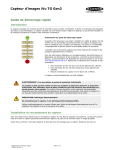


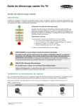

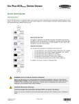
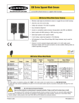
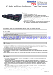

![iVu Plus BCR Gen2 Instruction Manual (Online Only) [ 179047 ]](http://vs1.manualzilla.com/store/data/005859145_1-6c6bbc2cdc90a8f85e92b64ee4999fc2-150x150.png)