1
iVu Plus TG Image Sensor
Instruction Manual
Original Instructions
B_3084219 Rev. D
18 March 2014
iVu Plus TG Image Sensor
Contents
...................................................................................................5
1 Overview of the Sensor
1.1 Typical iVu Applications
..............................................................................................................5
1.1.1 Label Inspection
.............................................................................................................. 5
1.1.2 Blister Pack Inspection
.................................................................................................... 6
1.1.3 Vial Stopper Inspection
................................................................................................... 6
1.2 Installation
...............................................................................................................................6
1.2.1 Components
................................................................................................................... 6
1.2.2 Installing and Connecting the Sensor
................................................................................ 8
1.2.3 Cable Connections
......................................................................................................... 10
1.2.4 iVu Trigger, Remote Teach, and I/O Waveforms
................................................................12
1.3 Major Features
.......................................................................................................................13
1.3.1 Demo Mode
.................................................................................................................. 13
1.3.2 Sensor Types
................................................................................................................ 14
1.3.3 Multiple Sensors
........................................................................................................... 14
1.3.4 Multiple Inspections
...................................................................................................... 15
1.3.5 iVu Plus Communication Summary of Ethernet and Serial
...................................................16
1.3.6 Trigger Modes
.............................................................................................................. 16
2 Home Screen
................................................................................................................ 18
2.1 Display Mode
......................................................................................................................... 18
2.1.1 Image with Annotations
.................................................................................................18
2.1.2 Image without Annotations
............................................................................................ 18
2.1.3 Inspection Statistics
.......................................................................................................19
3 Main Menu Reference
....................................................................................................21
3.1 Main Menu
..............................................................................................................................21
3.2 Inspection Menu
......................................................................................................................23
3.2.1 Sensors Menu
.............................................................................................................. 23
3.2.2 Motion Menu
................................................................................................................. 27
3.2.3 Properties Menu
........................................................................................................... 28
3.2.4 Stored Inspections
.........................................................................................................29
3.3 Imager Menu
.......................................................................................................................... 30
3.3.1 Auto Exposure
...............................................................................................................30
3.3.2 Exposure
...................................................................................................................... 31
3.3.3 Gain
............................................................................................................................ 31
3.3.4 Trigger
......................................................................................................................... 31
3.3.5 Focus
........................................................................................................................... 32
3.3.6 Strobe
..........................................................................................................................32
3.3.7 FOV (Field of View)
........................................................................................................ 33
3.4 System Menu
..........................................................................................................................35
3.4.1 Mode
........................................................................................................................... 35
3.4.2 System Configuration
..................................................................................................... 35
3.4.3 System Information
....................................................................................................... 36
3.4.4 Lock device
..................................................................................................................36
3.4.5 Communications
............................................................................................................37
3.4.6 Discrete I/O
.................................................................................................................. 46
3.4.7 Display Settings
............................................................................................................ 49
3.4.8 Reboot Sensor
...............................................................................................................50
3.4.9 Firmware Update
........................................................................................................... 50
3.5 Logs Menu
..............................................................................................................................50
3.5.1 Inspection Logs
............................................................................................................. 50
3.5.2 System Logs
................................................................................................................. 52
3.5.3 Communication Logs
...................................................................................................... 52
4 Setting up an Inspection
4.1 Acquiring a Good Image
5 Configuring Sensors
5.1
5.2
5.3
5.4
...............................................................................................54
........................................................................................................... 54
.....................................................................................................57
Sensor Configuration Shortcut Menu
......................................................................................... 57
Configuring an Area Sensor
...................................................................................................... 59
Configuring a Blemish Sensor
....................................................................................................62
Configuring a Match Sensor
...................................................................................................... 65
5.4.1 Remote Teach
............................................................................................................... 68
5.5 Configuring a Sort Application
................................................................................................... 69
5.6 Configuring Motion
................................................................................................................. 70
5.6.1 Number of Edges
........................................................................................................... 71
5.6.2 Sensitivity
.................................................................................................................... 71
5.6.3 Rotation
....................................................................................................................... 71
iVu Plus TG Image Sensor
5.7 Configuring Multiple Sensors in the Inspection
6 Communications Guide
............................................................................71
................................................................................................ 73
6.1 iVu Plus Communication Summary of Ethernet and Serial
............................................................ 73
6.1.1 Communication Channels
...............................................................................................73
6.1.2 Industrial Ethernet
........................................................................................................73
6.1.3 Command Channel
.........................................................................................................73
6.1.4 Data Export
.................................................................................................................. 74
6.1.5 Image Export
............................................................................................................... 75
6.2 Enabling Communications
........................................................................................................76
6.2.1 Setting Up Ethernet Communications
...............................................................................76
6.2.2 Setting Up Serial Communications
................................................................................... 80
6.3 Testing and Troubleshooting iVu Plus Communications
................................................................. 83
6.3.1 Understanding the Communication Log
............................................................................. 83
6.3.2 Ethernet I/O
................................................................................................................ 84
6.3.3 Serial I/O
.................................................................................................................... 84
6.4 Command Channel Primer
....................................................................................................... 86
6.4.1 Command Channel Commands
........................................................................................ 86
6.4.2 Conventions Used for Examples
....................................................................................... 87
6.4.3 Examples
.....................................................................................................................88
6.4.4 Command Channel Reference
......................................................................................... 88
6.4.5 Multiple Sensors Inspection
............................................................................................95
6.4.6 Command Channel Command Status Register
................................................................... 96
6.4.7 Command Channel Error Codes
....................................................................................... 96
7 Industrial Ethernet Overview
.......................................................................................98
7.1 Device Setup
......................................................................................................................... 98
7.1.1 Set IP Address
............................................................................................................. 98
7.1.2 Set Industrial Ethernet Protocol (EIP/Modbus/TCP/PCCC)
................................................... 98
7.1.3 Set Trigger Mode
.......................................................................................................... 98
7.2 Supported Functions
................................................................................................................ 98
7.2.1 iVu Input Values
............................................................................................................ 98
7.2.2 iVu Output Values
..........................................................................................................99
7.3 Sensor Operation
.................................................................................................................... 99
7.3.1 General Command Execution
........................................................................................ 100
7.4 EtherNet/IP
.......................................................................................................................... 100
7.4.1 RSLogix5000 Configuration
........................................................................................... 100
7.4.2 Inputs to iVu (Outputs from PLC)
................................................................................... 106
7.4.3 Outputs from the iVu (Inputs to the PLC)
........................................................................ 107
7.4.4 Multiple Sensors Mapping Options
.................................................................................. 110
7.4.5 Input and Output Flags Bits
...........................................................................................115
7.4.6 Configuration Assembly Object
...................................................................................... 116
7.4.7 Data Formats
.............................................................................................................. 116
7.4.8 Minimum Requested Packet Inverval (RPI) Value
.............................................................116
7.5 Modbus/TCP
..........................................................................................................................117
7.5.1 Holding Registers
......................................................................................................... 117
7.5.2 Output Registers
..........................................................................................................117
7.5.3 Multiple Sensors Mapping Options
.................................................................................. 122
7.5.4 Input and Output Coils
..................................................................................................126
7.6 PLC5 and SLC 5 (PCCC)
..........................................................................................................127
7.6.1 Configuration
............................................................................................................. 127
7.6.2 Inputs to iVu (Outputs from PLC)
................................................................................... 129
7.6.3 Outputs from iVu (Inputs to PLC)
................................................................................... 129
7.6.4 Multiple Sensors Mapping Options
.................................................................................. 134
7.6.5 Input and Output Flags
................................................................................................. 138
7.7 Sample Timing Diagram
........................................................................................................ 139
7.8 Command Channel Command Status Register
........................................................................... 142
7.9 Diagnostic Guide
................................................................................................................... 142
7.9.1 Ethernet Diagnostics
................................................................................................... 142
7.9.2 Networking and TCP/IP Diagnostics
............................................................................... 143
7.9.3 Industrial Protocols Troubleshooting
.............................................................................. 145
7.10 Additional Information
......................................................................................................... 147
7.10.1 iVu Command Channel Commands (iVu Command Channel over Industrial EtherNet)
.......... 147
8 Debugging Inspections
.............................................................................................. 152
8.1 iVu Emulator
.........................................................................................................................152
8.2 How to Round-Trip Debug Using the Emulator
........................................................................... 152
8.2.1 How to Debug Using the Emulator from a PC
................................................................... 152
8.2.2 How to Debug Using the Emulator from the USB Flash Drive
............................................. 153
9 Updating the Sensor
.................................................................................................. 154
9.1 Update Process
..................................................................................................................... 154
9.2 How to Set or Modify a Device Name
........................................................................................154
9.3 How to Reset the Sensor Password
.......................................................................................... 155
iVu Plus TG Image Sensor
9.4 How to Use Bitmap Image Files with the iVu Emulator
10 LED Indicator Troubleshooting
................................................................ 155
................................................................................. 157
10.1 Errors
.................................................................................................................................157
10.2 Warnings
............................................................................................................................ 157
11 Product Support and Maintenance
............................................................................ 158
11.1 Product Support
.................................................................................................................. 158
11.2 Maintenance
....................................................................................................................... 158
11.3 Banner Engineering Corp Limited Warranty
............................................................................ 159
iVu Plus TG Image Sensor
1 Overview of the Sensor
The iVu Plus TG Series sensor sensor is used to monitor parts for type, size, orientation, shape, and location. No PC is
required to configure the sensor. Instead, the sensor has a color touch screen display (either integrated with the sensor or
available as a remote display) that you can use to set up and monitor inspections. The following features are available:
•
•
•
•
•
•
•
•
•
•
•
•
Self-contained image sensor; no PC required
Easy configuration: install/connect iVu, select sensor type, acquire image, set inspection parameters
Intuitive interface and sophisticated features make powerful inspection capabilities simple
Multiple sensor configuration
GUI available in multiple languages (English, French, German, Italian, Spanish, Japanese, Simplified Chinese,
Portuguese, and Turkish)
68.5 mm (2.7 in) touch-screen LCD display or separate touch screen display that mounts remotely from the sensor
to allow easy access to the user interface and to view inspection images
Four sensor types in one package—a match sensor that determines whether a pattern on a label or part matches a
reference pattern; a sort sensor that can recognize and sort up to ten different patterns within the same
inspection; an area sensor that detects whether or not a particular feature (or features) is present; and a blemish
sensor that detects flaws on parts
Robust IP67 housing with integrated lighting (red, blue, green, or infrared)
M12 connector with 10 to 30 V dc for power supply and PNP or NPN output
External trigger input, remote TEACH input, and external strobe output available
USB port for uploading and downloading of inspections and log files for easy updating and diagnostics
Software emulator for PC available to evaluate inspections offline based on bitmap images or inspection logs
1.1 Typical iVu Applications
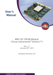
1.1.1 Label Inspection
Figure 1. Label Inspection
A manufacturer packages a number of products in similar packaging and needs a cost-effective way to ensure that only
like products are packaged together. Additionally, they want to verify that all the products have labels.
To verify each product, an iVu Series sensor is configured for a Match inspection. An image of a good product package is
captured. When the inspection is running, if the sensor detects a package with a different or missing label, the sensor
sends a fail output to the line, and the product is rejected.
5
iVu Plus TG Image Sensor
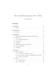
1.1.2 Blister Pack Inspection
Figure 2. Blister Pack Inspection
Because of tightened federal regulations that make the quality of pharmaceutical packaging increasingly critical, when
tablets are inserted into a blister pack, manufacturers need to verify that all the blisters in a pack have been filled with
unbroken tablets.
To verify each blister in the pack, use an iVu Series sensor configured for an Area inspection. The sensor inspects each
blister pack to make sure that each blister contains an unbroken tablet.
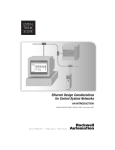
1.1.3 Vial Stopper Inspection
Figure 3. Vial Stopper Inspection
In the pharmaceutical industry where vials are filled with tablets in a high-speed application, as soon as each vial is filled,
a stopper must be properly inserted into the vial.
To ensure that a stopper is properly inserted as each vial leaves the filling station, an iVu Series sensor—set up for an Area
application and motion parameters enabled—verifies that the vial has a stopper inserted into its neck and that the stopper
is positioned correctly to provide a proper seal on the glass vial. If the stopper is missing or incorrectly positioned, then
the sensor sends a fail output to the line.
1.2 Installation
1.2.1 Components
iVu with Integrated Display
The iVu Series sensor comes fully assembled with the lens and an integrated ring light if so ordered. The integrated
touchscreen display has a plastic cover to protect the display. Remove this cover when setting up the sensor. When the
display is not in use be sure to keep the display covered to protect it.
6
iVu Plus TG Image Sensor
If an integrated ring light is not used, another light source is needed. Various lights are available from Banner. Operating
in external trigger mode requires a triggering source (for example, the Banner WORLD-BEAM® QS18VN6D sensor).
1
LED - Green: Ready; Red: Error
2
LED - Green: Pass; Red: Fail
3
Ethernet I/O LED
4
Focusing Window
5
Focusing Window Locking Clip
6
Integrated Display
A
8-pin Euro-style (M12) female USB Cable Connector
B
I/O Cable Connector
C
12-pin Euro-style (M12) male Power and I/O Cable Connector
C
A
B
Mounting Bracket Mounting Holes (uses supplied three M4 x 4 mm screws)
iVu with Remote Display
The iVu sensor for use with a Remote Display comes fully assembled with the lens and an integrated ring light if so
ordered. Although the Remote Display is not required for normal sensor operation, it is needed to set up the sensor and to
monitor inspections.
If an integrated ring light is not used, another light source is needed. Various lights are available from Banner. Operating
in external trigger mode requires a triggering source (for example, the Banner WORLD-BEAM® QS18VN6D sensor).
7
iVu Plus TG Image Sensor
1
LED - Green: Ready; Red: Error
2
LED - Green: Pass; Red: Fail
3
Ethernet I/O LED
4
Focusing Window
5
Focusing Window Locking Clip
A
Remote Display connector
B
Power and I/O Cable connector
C
USB connector
D
Ethernet connector
B
A
C
D
Mounting Bracket Mounting Holes (uses supplied three M4 x 4 mm screws)
1.2.2 Installing and Connecting the Sensor
The iVu Plus TG sensor requires a bracket for mounting. Three brackets are available from Banner. The brackets allow the
sensor to be mounted either perpendicular to the part or at an adjustable angle.
Thread three M4 x 4mm screws through the bracket into the mounting holes in the bottom of the sensor. Tighten all three
screws.
Table 1: iVu Brackets
SMBIVURAL
SMBIVURAR
8
SMBIVUU
iVu Plus TG Image Sensor
Installing a Filter on iVu Series Sensors
Installing a Filter on the Micro Video Lens Model
To install a filter on the iVu Series sensor with Micro Video Lens, use the illustration as a guide and follow the steps
listed below.
CAUTION: Failure to follow these instructions may cause damage to your iVu Series sensor.
Micro Video Lens Models
A
Lens
B
Focusing Window
C
Locking Clip
D
Locking Screw
E
Filter Cap
F
Filter
1. Remove the Focusing Window locking screw (D) using the 1/16 in. hex key.
NOTE: The Locking Clip (C) inserts in a groove near the top of the Focusing Window (B).
When removing the window, the Locking Clip will be loose. Be careful not to lose the clip
while removing the window.
2. Unscrew the Focusing Window by turning it clockwise approximately 5 complete turns or until the Focusing
Window disengages from the light/lens assembly.
NOTE: The light/lens assembly may include an integrated ring light or a blank disk if an
integrated ring light is not used. Be careful that the light/lens assembly does not pull out
when removing the Focusing Window. Give a slight tug on the Focusing Window when you
think you've unscrewed it far enough. If the lens assembly moves with the window,
continue to rotate the window clockwise until the lens assembly does not move.
3. Set the Focusing Window aside. Be careful not to get any debris on the window's O-ring.
4. If present, remove the protective covering on the filter.
5. Place the filter into the Filter Cap and press the cap onto the lens.
6. After the filter is installed, place the Focusing Window back into the housing while inserting the Locking Clip into
the groove as shown.
B
Groove
9
C
iVu Plus TG Image Sensor
7. Press the Focusing Window onto the housing to make sure that it seats correctly (no gap between the window
and housing). Rotate the window counter-clockwise at least two turns.
8. Replace the locking tab screw but do not tighten until you have set up and focused the sensor again.
Installing a Filter on the C-Mount Lens Model
To install a filter on the iVu Series sensor with C-Mount Lens, use the illustration as a guide and follow the steps listed
below.
CAUTION: Failure to follow these instructions may cause damage to your iVu Series sensor.
C-Mount Lens Models
C
E
B
D
C
A
C-Mount Lens
B
Lens Enclosure
C
Retainer Ring (optional)
D
Filter (optional)
E
Filter Retainer Ring Tool
NOTE: Filter Kits are available separately.
A
1. Remove the Lens Enclosure and Lens.
2. Install filter behind the retainer ring. Make sure it is fully seated.
3. Using the provided retainer ring tool, thread the retainer ring into the sensor until it firmly seats the filter.
4. Replace the Lens and Lens Enclosure on the camera.
CAUTION: Electrostatic Discharge
Avoid the damage that electrostatic discharge (ESD) can cause to the Sensor.
Always use a proven method for preventing electrostatic discharge when installing a lens or
attaching a cable.
1.2.3 Cable Connections
Cable Connections for Integrated Display
The cable connections on the iVu Plus with integrated display are shown below, and power I/O connections (C) are defined
in the Power I/O Connections table below.
A
USB Connector
B
Ethernet Connector
C
Power I/O Connector
NOTE: Micro video lens model shown, C-Mount model
connections are identical.
C
A
B
10
iVu Plus TG Image Sensor
Power I/O Connections
Pin #
Wire Color
Description
Direction
1
White
Output 1
Output
2
Brown
10-30V dc
Input
3
Green
Output 2
Output
4
Yellow
Strobe Out (5V dc only)
Output
5
Gray
Remote Teach
Input
6
Pink
External Trigger
Input
7
Blue
Common (Signal Ground)
Input
8
Red
Ready
Output
9
Orange
Output 3
Output
10
Light Blue
RS-232 TX
Output
11
Black
RS-232 Signal Ground
Output
12
Violet
RS-232 Rx
Input
Cable Connections for Remote Display
The cable connections on the iVu Plus with remote display are shown below, and power I/O connections (B) are defined in
the Power I/O Connections table below.
A
Remote Display Connector
B
Power I/O Connector
C
USB Connector
D
Ethernet Connector
NOTE: Micro video lens model shown, C-Mount model
connections are identical.
B
A
C
D
Power I/O Connections
Pin #
Wire Color
Description
Direction
1
White
Output 1
Output
2
Brown
10-30V dc
Input
3
Green
Output 2
Output
4
Yellow
Strobe Out (5V dc only)
Output
5
Gray
Remote Teach
Input
6
Pink
External Trigger
Input
7
Blue
Common (Signal Ground)
Input
8
Red
Ready
Output
Orange
Output 3
Output
10
9
Light Blue
RS-232 TX
Output
11
Black
RS-232 Signal Ground
Output
12
Violet
RS-232 Rx
Input
11
iVu Plus TG Image Sensor
1.2.4 iVu Trigger, Remote Teach, and I/O Waveforms
The iVu has two input signals—Trigger and Remote Teach. The default setting is to detect the low to high transition. This
setting can be changed in the Main Menu > System > Discrete I/O > Input Polarity screen on the sensor.
PNP (Low-to-High) Trigger and Remote Teach Input Waveforms
Power up
Wire Color
Function
Pink
Trigger
Gray
Remote
Teach
The sensor triggers from low to high, and Remote Teach behaves electrically like trigger.
NPN (High-to-Low) Trigger and Remote Teach Input Waveforms
Power up
Wire Color
Function
Pink
Trigger
Gray
Remote
Teach
The sensor triggers from high to low, and Remote Teach behaves electrically like trigger.
NOTE: If the device used to trigger or remote teach the iVu Plus TG is a sinking device, these are the
options regarding the use of a pull-up resistor:
Option 1: Put a pull-up resistor, rated approximately 1k ohm, between the sensor's positive (+)
voltage and the sensor's input as shown below.
Sinking
VCC
iVu
Trigger Input
1k ohm
Pullup Resistor
Remote Teach Input
NPN
Option 2: Enable the Input Pullup in the iVu Plus TG software (Main Menu > System > Discrete I/O
> Input Pullup).
12
iVu Plus TG Image Sensor
iVu Output Waveforms
Function
Ready
Outputs 1,2, and 3
(Pass)
(Fail)
(Pass)
(Pass)
(Fail)
(Pass)
(Pass)
(Fail)
(Pass)
(Pass)
(Fail)
(Pass)
(Set as Active Pass)
Outputs 1, 2, and 3
(Set as Active Fail)
Strobe Out
(Configure as External
& Expose Based)
Figure 4. PNP Outputs
Function
Ready
Outputs 1, 2, and 3
(Set as Active Pass)
Outputs 1, 2, and 3
(Set as Active Fail)
Strobe Out
(Configure as External
& Expose Based)
Figure 5. NPN Outputs
1.3 Major Features
1.3.1 Demo Mode
The first time you power up the iVu Plus TG sensor, it starts in Demo Mode. Demo Mode uses stored images and inspection
parameters that demonstrate how the sensor is set up without having to worry about focus, lighting, or triggers. In this
mode, you can learn how to make adjustments while working with the different sensor types and observing how the
adjustments affect the sensor results. To exit Demo Mode, go to Main Menu > System > Mode and select Live from the
drop-down list. When you exit Demo Mode, the sensor reboots into its normal operating mode with default settings.
13
iVu Plus TG Image Sensor
NOTE: Switch between Live Mode and Demo Mode any time by going to Main Menu > System >
Mode.
1.3.2 Sensor Types
The iVu Plus TG sensor includes four Sensor Types:
•
•
•
•
Area Sensor
Blemish Sensor
Match Sensor
Sort Sensor
Area Sensor
An Area type sensor is used to ensure that a feature, or multiple features, are present on a part. When setting up the
sensor for an Area inspection, a feature, such as a drilled hole, is identified as well as the size (area) expected. If there is
more than one of the identified features on a part, the number expected can be set as well. During the inspection, the
sensor verifies that each part or package includes the specified number of features. Some example applications include:
•
•
•
•
Inspections that check for drilled holes on a part
Inspections that check for correctly stamped parts
Inspections that ensure proper packaging (for example, check that a packing slip exists in or on a box; test
whether a vial is properly capped)
Inspections of blister packs
Blemish Sensor
A Blemish type sensor can be used to find flaws on a part (for example, scratches on a disc), or it can be used to make
sure a feature exists on a part. Although verifying a feature is present on a part is more commonly an Area sensor
application, a Blemish sensor may be a better option when dealing with variable materials or uneven lighting. Some
example applications include:
•
•
Inspections that check for scratches on a part, and reject parts where the scratches are too numerous or larger
than acceptable
Inspections that check for the presence of some label or marking on a part that may vary in color
Match Sensor
A Match type sensor is used to verify that a pattern, shape, or part in any orientation matches a reference pattern. The
reference pattern is taught during setup. A reference pattern might include alphanumeric characters, logos, or any other
shapes. During an inspection, the sensor checks that each part or package being inspected matches the reference pattern.
Additionally, if there is more than one of the identified pattern, the number expected can be set.
Some example applications include:
•
•
•
•
•
Date/Lot code inspections
Label inspections
Part etching inspections
Part orientation inspections
Part shape inspections
Sort Sensor
A Sort sensor type that can recognize and sort up to ten different patterns within the same inspection. Each reference
pattern is taught during setup and stored in one of ten pattern memory locations. A reference pattern might include
alphanumeric characters, logos, or any other shapes, and the pass criteria can be set for any or all of the patterns.
Some example application include:
•
•
Identify and sort parts on a production line
Ensure that several different parts are present in a package
1.3.3 Multiple Sensors
Firmware versions 1.2.0 and newer include multiple sensor functionality. Each part inspected can now use multiple sensors
to inspect more than one feature. Up to 30 such inspections can be created and stored on the device.
14
iVu Plus TG Image Sensor
1.3.4 Multiple Inspections
The iVu Plus supports multiple inspections that facilitate storing and controlling up to 30 inspections of different Sensor
Types.
Adding a New Inspection
To Add a new stored inspection:
1. Go to Main Menu > Inspection > Stored Inspections and click Add New.
2. Select the Sensor Type for the new inspection, and click Next.
3. Click Done. The newly created inspection will now be the current inspection.
Changing Running Inspections
To change the running inspection:
1. From the Home screen, click the Yellow button in the top center of the screen that displays the currently running
inspection to display all the stored inspections.
2. Select the inspection to start and click the Start Running button that appears below it.
15
iVu Plus TG Image Sensor
1.3.5 iVu Plus Communication Summary of Ethernet and Serial
The iVu Plus communicates with other devices via Ethernet or a UART serial communications port (RS-232). In order to
establish an Ethernet connection to the sensor, the external device must be configured with the correct IP address and TCP
port to communicate. To use the serial communications connection, port settings for baud rate, data bits, parity, and stop
bits must be configured on the iVu Plus to match the settings of the external device.
Communication Channels
The iVu Plus TG supports up to four communications channels. To access the channels, go to Main Menu > System >
Communications.
•
•
•
•
Command Channel—a bi-directional communication protocol that currently supports ASCII and enables other
devices to remotely control the iVu Plus sensor and access sensor results
Industrial Ethernet—a bi-directional communication channel that allows the user to control the sensor and access
sensor results using Ethernet/IP, Modbus/TCP, or PCCC protocol
Data Export—used to export selected inspection data to a remote device
Image Export—used to export inspection images to a remote device
Data export and command channel can be configured for either Ethernet or Serial I/O (but not both); image export is only
available over Ethernet. The table below briefly summarizes valid communication channel configuration options.
Command Channels
Scenario #1
Scenario #2
Scenario #3
Ethernet
Serial I/O
Ethernet
Serial I/O
Ethernet
Serial I/O
Command Channel
Yes
No
No
Yes
Yes
No
Industrial Ethernet
Yes
No
Yes
No
Yes
No
Data Export
Yes
No
Yes
No
No
Yes
Image Export
Yes
No
Yes
No
Yes
No
1.3.6 Trigger Modes
The iVu Plus TG has five trigger modes that determine how the sensor captures and processes images:
•
•
External
Internal
16
iVu Plus TG Image Sensor
•
•
•
Free Run
Industrial Ethernet Only
Command
Select one of the trigger modes by accessing Main Menu > Imager > Trigger on the iVu touch screen display. Trigger
on page 31 describes these trigger modes in more detail.
17
iVu Plus TG Image Sensor
2 Home Screen
The Home screen on the iVu Series sensor display is used to monitor inspections and to configure the sensor. Normally,
the part being inspected is centered on the screen with the feature of interest bounded by the Region of Interest (ROI), a
rectangle as shown below. The ROI can be rotated and resized, and is highlighted when selected for adjustment.
In the following graphic, there are 2 ROI because it is a multi sensor inspection. The green annotations indicate the object
passes, and the red annotations indicate a failure. This sample inspection failed as shown by the red X next to the Display
mode button.
2.1 Display Mode
Main Menu > Home > Display Mode (icon)
Use the display mode button on the upper left corner of the screen to cycle through all three display modes. The 3 display
modes include: Image with Annotations, Image without Annotations, and Inspection Statistics.
2.1.1 Image with Annotations
Click the display mode icon
pass or fail in the ROI.
to show the image with the annotations on. The green or red areas indicate sensors that
2.1.2 Image without Annotations
Click the
display mode icon to see the image without the annotations from the sensors.
18
iVu Plus TG Image Sensor
2.1.3 Inspection Statistics
To access the Inspection Statistics, click the Display mode icon
.
The Inspection Statistic mode has three pages:
•
•
•
History
Inspection Result
Inspection Inputs
Click the arrows to access the other pages.
Inspection Results
The Inspection Result screen shows data about the current inspection being viewed.
The table contains result of each sensor in the inspection. To view details of each sensor, click on the + icon. If a sensor
fails, its box will be drawn in RED. An icon besides the sensor name indicates the reason of its failure.
History
The History screen shows inspection history from sensor reboot, or the last time the statistics were reset, including:
•
•
•
•
•
Total Frames—Total number of objects counted
Passed—running total of parts that passed inspection
Failed—running total of parts that failed inspection
Missed triggers—running total of missed triggers
Time Range—minimum and maximum inspection times observed
Click the Reset button to reset statistics.
The table contains history of each sensor in the inspection. Data of each sensor can be expanded or collapsed as required
using the +/–. The green area indicates the sensor passed, red indicates fail. If a sensor fails, an icon besides the sensor
name will indicate the reason of failure.
19
iVu Plus TG Image Sensor
Inspection Inputs
The Inspection Input page has the sensor settings. Use this page to verify what inspection input settings were used on the
latest inspection. Click + to expand the inspection information, or – to collapse the inspection information. Use the right
arrows as a shortcut go to a sensor setting screen.
20
iVu Plus TG Image Sensor
3 Main Menu Reference
3.1 Main Menu
The Main Menu has four sections:
Inspection - to modify inspection settings
Imager - to run the Auto Exposure routine and to make adjustments to functions like exposure, gain, and strobe
System - to select the sensor Type and to manage the device
Logs - to configure and view System and Inspection Logs
21
iVu Plus TG Image Sensor
Inspection
System
Mode
Live
Demo
Sensors
ROI Type
Area
Intensity Range
Configuration
Reset to Defaults
Pass Count
Blemish
Information
ROI Type
Lock Device
Sensitivity
Communications
Edge Length Range
Pass Count
Match
Save to USB
Load from USB
Area Range
Sensor Type selection determines
first menu item under inspection
ROI Type
Connection
Ethernet I/O
Map
Serial I/O
Status
Industrial Ethernet
View Logs
Command Channel
Connection
Data Export
Connection
Percent Match
Delimiters
Rotation Range
Pass Count
Data to Export
Timeout
Output Format
Sort
Saved Patterns
Advanced
Percent Match
Image Export
Rotation Range
Image Type
Pass Criteria
Advanced
Timeout
Discrete I/O
Input Polarity
Input Pullup
Number of Edges
Motion *
* Visible when Motion = Enabled
Output Type
Sensitivity
Output 1
Rotation
Output 2
Output 3
Inspection Name
Properties
Inspection ID
Motion **
Display Settings
** Visible when Inspection
contains Area or Blemish
Fail Hold Time
LCD Timeout
Touch Calibration
Stored Inspections
Select
Reboot Sensor
Add New
Advanced
Firmware Update
Startup
Language
Delete
Set Name / ID
Imager
Auto Exposure
Exposure
Logs
Inspection Logs
View Logs
Gain
System Logs
Setup
Trigger
Communication Logs
Industrial Ethernet
View Logs
Command Channel
Setup
Focus
Strobe
External
FOV
Maximize FOV
Internal
Data Export
Image Export
Modify FOV
Locked Sensor Menus
Locked
Connection
Inspection Logs
System Logs
Communication Logs
Unlock Sensor
22
iVu Plus TG Image Sensor
3.2 Inspection Menu
Main Menu > Inspection
The Inspection menu icon is located on the Main Menu and is where settings for inspection can be adjusted. Each type of
sensor has specific settings that are available. It is also where stored inspections can be managed.
3.2.1 Sensors Menu
Main Menu > Inspection > Sensors
This menu shows the list of sensor(s) that are included in the current inspection. Use the Add Sensor button add a new
sensor into the current inspection.
Area Menu
Main Menu > Inspection > Sensors > Area
When configured as an Area sensor, the sensor is used to ensure that one or more features of interest are present on a
part. To configure as an Area sensor, set four parameters:
•
•
•
•
ROI Type (Rectangle, Elliptical, or Circle) and size
Intensity Range (range of gray scale values) of a feature of interest
Area Range, or size, of a feature of interest
Pass Count
To see a working example of the sensor configured as an Area sensor, see Demo Mode.
23
iVu Plus TG Image Sensor
ROI Type
Main Menu > Inspection > Sensors > Area > ROI Type
The Region of Interest (ROI) is the user-defined area on the screen that the sensor will analyze. The ROI Type can be
rectangular, elliptical, or circular. From the menu at the bottom of the ROI Type screen, select the ROI Type to use for the
inspection. Adjust the ROI as appropriate for your inspection. An ROI can be as large as the entire Field of View (FOV).
Intensity Range
Main Menu > Inspection > Sensors > Area > Intensity Range
Intensity Range is the range of gray scale values the sensor should look for. To set the Intensity Range, use the eye
dropper on the left of the screen to select the target feature, then use the slider bar at the bottom of the display to fine
tune the selection. As the slider bar is moved, green highlighted areas indicate objects the sensor finds.
NOTE: Objects that are colored yellow are found, but filtered out. This is because the objects fall
outside of the Area Range. See Area Range to adjust this setting.
Area Range
Main Menu > Inspection > Sensors > Area > Area Range
The Area Range is used to set the size limits of a feature of interest. Use the slider bar at the bottom of the display to
select the range. Areas are measured by counting pixels. For example, a rectangular feature that is 100 pixels wide by 200
pixels tall will have an area of roughly 20,000 pixels.
Pass Count
Main Menu > Inspection > Sensors > Area > Pass Count
The Minimum Pass Count is the minimum number of parts, labels, or features expected to fall within the specified criteria;
the Maximum Pass Count is the maximum number expected to fall within the specified criteria. These settings are used to
determine the pass or fail result of the inspection.
Blemish Menu
Main Menu > Inspection > Sensor > Blemish
When configured as a Blemish sensor, it can be used to find flaws on a part (for example, scratches on a disc). It can be
used to make sure the a feature exists on a part. Although this is more commonly an application for a sensor configured as
an Area sensor, a Blemish sensor may be a better option to find a feature when dealing with variable materials or uneven
lighting. Some sample applications include:
•
•
Inspections that check for scratches on a part, and reject parts where the scratches are too numerous or larger
than acceptable
Inspections that check for the presence of some label or marking on a part that may vary in color
To configure as a Blemish sensor, select the ROI type, and set the Sensitivity, Size Filter, and Pass Count.
24
iVu Plus TG Image Sensor
ROI Type
Main Menu > Inspection > Sensors > Blemish > ROI Type
The Region of Interest (ROI) is the user-defined area on the screen that the sensor will analyze. The ROI Type can be
rectangular, elliptical, or circular. From the menu at the bottom of the ROI Type screen, select the ROI Type to use for the
inspection. Adjust the ROI as appropriate for your inspection. An ROI can be as large as the entire Field of View (FOV).
Sensitivity
Main Menu > Inspection > Sensors > Blemish > Sensitivity
Sensitivity is used to fine-tune how sensitive the sensor is to finding blemish or other edges within the ROI. The Sensitivity
value helps account for light variations that might affect how well the sensor detects edges on inspected parts. The
Sensitivity scale is from 0 to 100 where 0 means least sensitive and 100 means most sensitive. If set near 0, the sensor
will only find very sharp edges with strong contrast. If set near 100, the sensor will find very dim or blurry edges, and may
be unstable.
Edge Length Range
Main Menu > Inspection > Sensors > Blemish > Edge Length Range
The sensor counts all the edge pixels it detects in the ROI. The bar at the bottom of the Edge Length Range screen shows
all the different contiguous edge segments found. Edge segments within the two brackets [ ] are highlighted in green and
those outside the brackets are ignored and colored yellow. Use the slider bar to specify the edge length range in pixels.
Edges found within this range will be considered to calculate the Pass Count.
Pass Count (Pixels)
Main Menu > Inspection > Sensors > Blemish > Pass Count
The Minimum Pass Count is the minimum number of pixels expected to fall within the specified criteria; the Maximum Pass
Count is the maximum number of pixels expected to fall within the specified criteria. These settings are used to determine
the pass or fail result of the inspection.
Match Menu
Main Menu > Inspection > Sensors > Match
When the sensor is configured as a Match sensor, set the ROI Type, Percent Match, Rotation Range, Pass Count, and
Timeout for the inspection. To see a working example of the sensor configured as a Match sensor, see Demo Mode.
25
iVu Plus TG Image Sensor
ROI Type
Main Menu > Inspection > Sensors > Match > ROI Type
Sensors The Region of Interest (ROI) is the user-defined area on the screen that the sensor will analyze. The ROI Type can
be rectangular, elliptical, or circular. From the menu at the bottom of the ROI Type screen, select the ROI Type to use for
the inspection. Adjust the ROI as appropriate for your inspection. An ROI can be as large as the entire Field of View (FOV).
Percent Match
Main Menu > Inspection > Sensors > Match > Percent Match
The Percent Match setting adjusts for how closely the inspected part or label matches the reference part or label. The
Percent Match scale is from 0 to 100 where 0 is the most tolerant and 100 is the least tolerant. Move the slider to the left
or to the right.
Rotation Range
Main Menu > Inspection > Sensors > Match > Rotation Range
The Rotation Range sets the expected rotation of parts or labels during an inspection. For example, a value of 45 means
that the part may rotate 45 degrees in either direction from the reference part and still pass. Move the slider from 0 to 180
degrees.
NOTE: The smaller the rotation range, the faster the inspection will run.
Pass Count
Main Menu > Inspection > Sensors > Match > Pass Count
The Minimum Pass Count is the minimum number of parts, labels, or features expected to fall within the specified criteria;
the Maximum Pass Count is the maximum number expected to fall within the specified criteria. These settings are used to
determine the pass or fail result of the inspection.
Timeout
Main Menu > Inspection >Sensors > Match > Timeout
When the sensor type is set as Match or Sort, this screen provides for adjusting the maximum time the inspection is
allowed to execute. A timeout error is reported in the case inspection runs out of time. If this value is set too high, the
sensor can miss triggers while trying to detect a bad pattern.
Sort Menu
The Sort sensor is used to identify and sort up to 10 stored patterns. The menu items in the Sort sensor provide for
managing stored patterns and configuring Sort sensor inspection parameters.
The Sort sensor cannot be added if any other sensors are selected. The Sort menu can only be reached when adding a
sensor.
26
iVu Plus TG Image Sensor
Saved Patterns
Main Menu > Inspection > Sensors > Sort > Saved Patterns
When configuring a Sort sensor type, there are 10 pattern storage locations available. The Saved Patterns screen is used
to save a taught pattern to an empty pattern storage location or to overwrite an existing pattern. This screen is also where
patterns can be deleted from a storage location, named, or renamed.
Percent Match
Main Menu > Inspection > Sensors > Sort > Percent Match
The Percent Match setting adjusts for how closely the inspected part or label matches the reference part or label. The
Percent Match scale is from 0 to 100 where 0 is the most tolerant and 100 is the least tolerant. Move the slider to the left
or to the right.
Rotation Range
Main Menu > Inspection > Sensors > Sort > Rotation Range
The Rotation Range sets the expected rotation of parts or labels during an inspection. For example, a value of 45 means
that the part may rotate 45 degrees in either direction from the reference part and still pass. Move the slider from 0 to 180
degrees.
NOTE: The smaller the rotation range, the faster the inspection will run.
Pass Criteria
Main Menu > Inspection >Sensors > Sort > Pass Criteria
There are four options to select from to define pass criteria for a Sort sensor inspection, which are described below using
an example where there are two saved patterns.
• Any Saved Pattern—Pass condition if the sensor matches either Pattern_1, Pattern_2, or both
• All Saved Patterns—Pass condition if the sensor matches both Pattern_1 AND Pattern_2
• Single Saved Pattern—Pass condition if the sensor matches either Pattern_1 OR Pattern_2, but NOT both
• Specific Saved Pattern (requires selecting a saved pattern to match; for example, Pattern_2) - Pass condition when
the sensor matches only Pattern_2
Timeout
Main Menu > Inspection > Sensors > Sort > Timeout
When the sensor type is set as Match or Sort, this screen provides for adjusting the maximum time the inspection is
allowed to execute. A timeout error is reported in the case inspection runs out of time. If this value is set too high, the
sensor can miss triggers while trying to detect a bad pattern.
3.2.2 Motion Menu
Main Menu > Inspection > Motion
Enable Motion when the part is expected to move or rotate. Motion settings also involve selecting the number of edges to
locate, adjusting sensitivity, and selecting whether or not rotation is enabled. These settings appear on the Inspection
Menu after Motion is set to 'Enabled'. Motion is enabled when Area and/or Blemish sensor are included in the inspection.
27
iVu Plus TG Image Sensor
Number of Edges
Main Menu > Inspection > Motion > Number of Edges
On the Number of Edges screen, use the radio buttons to select One Edge or Two Edges. If One Edge is selected, motion is
tracked in one direction (by default, horizontally); if Two Edges is selected, motion can be tracked horizontally and
vertically.
Sensitivity
Main Menu > Inspection > Motion > Sensitivity
Sensitivity is used to fine-tune how sensitive the sensor is to finding a reference edge. The Sensitivity value helps account
for light variations that might affect how well the sensor detects edges on inspected parts. The Sensitivity scale is from 0
to 100 where 0 means least sensitive and 100 means most sensitive. If set near 0, the sensor will only find very sharp
edges with strong contrast. If set near 100, the sensor will find very dim or blurry edges, and may be unstable due to
noise within the image.
Rotation
Main Menu > Inspection > Motion > Rotation
Rotation can be Enabled or Disabled. Select Enabled if the part can be expected to rotate during the inspection.
3.2.3 Properties Menu
Main Menu > Inspection > Properties
The Properties menu is used to select a Sensor Type and specify an Inspection Name. Additionally, if the Sensor Type is
Match or Sort, an option to define a timeout for the inspection.
Inspection Name
Main Menu > Inspection > Properties > Inspection Name
The Inspection Name screen displays the name of the current inspection. You can edit the name of the inspection here.
28
iVu Plus TG Image Sensor
Inspection ID
Main Menu > Inspection > Properties > Inspection ID
Click on the dropdown arrow to view a list of IDs assigned to all inspections on this device. Choose any unused ID to
change the ID of this inspection. The original ID will be marked as 'Unused'.
You may also swap the ID of this inspection with another inspection by selecting that inspection on the list.
3.2.4 Stored Inspections
Main Menu > Inspection > Stored Inspections
Stored Inspections is used to manage stored inspections. Management of stored inspections includes adding, deleting, and
specifying which inspection should be defined as the Startup inspection.
From the Stored Inspections menu click Select, Add New, Startup, Delete, or Set Name/ID
Select
Main Menu > Inspection > Stored Inspections > Select
This screen is used to select a new running inspection. Select the name of the inspection to start, and click the Start
Running button that displays.
Add New
Main Menu > Inspection > Stored Inspections > Add New
The Add New button is to add a new inspection. The sensor can store up to 30 inspections. When you add a new
inspection, it will begin running. When adding a new inspection, the Sensor Type and inspection name will be set.
29
iVu Plus TG Image Sensor
Startup
Main Menu > Inspection > Stored Inspections > Startup
The Startup button allows you to select the inspection to use as the startup inspection. The selected inspection will
automatically start after power up.
Delete Inspections
Main Menu > Inspection > Stored Inspections > Delete
The Delete button is used to delete stored inspections. Note that any running inspection, or the inspection marked as the
Startup inspection, cannot be deleted.
Set Name/ID
Main Menu > Inspection > Stored Inspections > Set Name/ID
The Set Name/ID button is used to change the name or ID of an inspection. You can sort the inspections in numeric or
alphabetical order by clicking on the icon beside the Help icon. Click on Name to edit the name of the inspection. Click on
ID to change the ID of the inspection.
3.3 Imager Menu
Main Menu > Imager
The Imager menu icon is on the Main Menu, and lists parameters that affect the characteristics of the captured image. The
Imager menu is used to access the Auto Exposure routine, manually adjust Exposure and Gain, set Trigger and Strobe
options as well as the size of the field of view (FOV).
3.3.1 Auto Exposure
Main Menu > Imager > Auto Exposure
Auto Exposure optimizes the exposure time and gain for the current lighting conditions. Multiple triggers are required to
complete this function.
30
iVu Plus TG Image Sensor
NOTE: The Auto Exposure option is not available on the Emulator.
3.3.2 Exposure
Main Menu > Imager > Exposure
Exposure is the amount of time the sensor allows light to energize the imager. Increasing the exposure time by moving
the slider to the right allows more light to energize the imager, which brightens the image.
NOTE: This feature is not effective on the emulator.
3.3.3 Gain
Main Menu > Imager > Gain
Gain is an electronic boost to the image signal. Increasing Gain by using the '-' and '+' keys or moving the slider to the
right increases image brightness without increasing exposure time. Note that Gain brightens both the light pixels and dark
pixels and may reduce the image quality.
NOTE: This feature is not effective on the emulator.
3.3.4 Trigger
Main Menu > Imager > Trigger
A Trigger is a signal that makes the sensor capture an image and inspect it. Use the radio buttons to select External
Trigger, Internal Trigger (default), Free Run, Industrial Ethernet Only, or Command.
•
If Internal Trigger is selected, triggers are based on timed intervals, and you need to select a trigger interval
between 10 and 10000 milliseconds.
31
iVu Plus TG Image Sensor
NOTE: If the interval is less than the inspection time, then missed triggers will occur.
•
•
•
•
If External Trigger is selected, inspections are triggered in response to an electrical signal on the Trigger input
line.
If Free Run is selected, the sensor automatically runs continuous inspections.
If Command is selected, the command channel is used to trigger the sensor from a remote device.
If Industrial Ethernet Only is selected, trigger commands from the Industrial Ethernet communications channel
only are accepted.
3.3.5 Focus
Main Menu > Imager > Focus
The Focus Number displayed at the bottom of this screen is used to fine-tune image focus. Loosen the lock on the lens
cover, turn the focus ring on the sensor until the Focus Number peaks (or the image appears sharp), then lock the focus
ring.
NOTE: For the Focus Number to work, the sensor must be triggering and the images must be similar
over time.
3.3.6 Strobe
Main Menu > Imager > Strobe
The Internal Strobe configures the operation of the integrated ring light. The External Strobe configures the operation of
an external light.
32
iVu Plus TG Image Sensor
External
Main Menu > Imager > Strobe > External
The External Strobe is a 5V output that can be used for an external light. Setting options are Always ON, Always OFF, or
Exposure Based. If Exposure Based is selected, then the external light is on during the time the sensor is capturing an
image.
Internal
Main Menu > Imager > Strobe > Internal
The Internal Strobe setting configures the operation of the integrated ring light. Strobe options are Always ON, Always
OFF, or Exposure Based. If Exposure Based is selected, then the ring light is on during the time the sensor is capturing an
image. For UV models, the Always ON option is not available.
3.3.7 FOV (Field of View)
Main Menu > Imager > FOV
33
iVu Plus TG Image Sensor
The field of view (FOV) is the area that the sensor can see at a given working distance. The working distance is the
distance from the sensor's lens cover to the part being inspected. By default, the sensor uses the entire FOV in its
operation. The effective FOV can be reduced in order to speed up the processing time of an inspection or to decrease
background noise.
Maximize FOV
Main Menu > Imager > FOV > Maximize FOV
If the FOV has been modified and you want to quickly get back to the default, click the Maximize FOV menu option to
restore the FOV to the entire sensor display.
Modify FOV
Main Menu > Imager > FOV > Modify FOV
Use this option to reduce or alter the size of the FOV.
34
iVu Plus TG Image Sensor
3.4 System Menu
Main Menu > System
The System menu icon is on the Main Menu, and is used to manage the sensor. The System menu provides for selecting
Sensor Mode, updating sensor firmware, backing up and restoring sensor Configuration, and other general system-level
operations.
3.4.1 Mode
Main Menu > System > Mode
The sensor has two operating modes:
•
•
Live Mode, which is the normal operating mode where the sensor captures live images, scans, and verifies
barcodes
Demo Mode, where inspections are run on stored images and inspection parameters.
The first time the device is powered up it starts in Demo Mode. Demo Mode uses stored images and inspection
parameters that demonstrate how the sensor is set up without having to worry about focus, lighting, or triggers. In
this mode, practice making adjustments while observing how the adjustments affect the results. To exit Demo
Mode go to Main Menu > System > Mode and select Exit Demo Mode. Upon exit, the sensor reboots into its
normal operating mode with default settings.
NOTE: Switch between Live Mode and Demo Mode any time by going to Main Menu > System >
Mode.
3.4.2 System Configuration
Main Menu > System > Configuration
The Sensor Configuration menu options are:
•
•
•
Save sensor Configuration to the USB flash drive
Load sensor Configuration from the USB flash drive
Reset the sensor Configuration to defaults
35
iVu Plus TG Image Sensor
Save to USB
Main Menu > System > Configuration > Save to USB
The Save to USB screen allows the sensor Configuration to be saved to a USB flash drive. The saved configuration
information can be used as a backup or as a way to clone configuration information for other sensors.
NOTE: On the Emulator, this option is Save Configuration.
Load from USB
Main Menu > System > Configuration > Load from USB
The Load from USB screen allows the sensor Configuration to be restored from a USB flash drive. This operation removes
all existing inspections and replaces them with inspections contained in the configuration file on the USB flash drive.
NOTE: On the Emulator, this option is Load Configuration.
Reset to Defaults
Main Menu > System > Configuration > Reset to Defaults
Resets all sensor configurations to the factory defaults. This operation will remove all existing inspections and replace them
with factory default settings.
3.4.3 System Information
Main Menu > System > Information
The Information screen displays the following sensor information:
•
•
•
•
•
•
•
Serial Number
Firmware Version
Boot Number
Up Timer—the time elapsed since last boot of the sensor
Hour Count—the total hours of operation in the sensor's lifetime
Model Number
Device Name
Click the right-arrow next to the Sensor Name field to display a software keyboard that allows you to change the Sensor
Name. You may set the sensor name in English on the device. To set the sensor in any other language, please use the
Emulator software.
3.4.4 Lock device
Main Menu > System > Lock device
This option provides for locking the sensor to prevent accidental modification of settings. When locked, the sensor only
provides access to pass/fail statistics, as well as the ability to view logs and to save them to a USB device. A lock icon in
the upper left corner of the sensor display indicates that the sensor is locked. Note that the sensor can be locked with or
without a password. If a password is not used, unlock the sensor by clicking on the Unlock device menu. When a password
36
iVu Plus TG Image Sensor
is used, it must be 4 digits entered using the software keypad. If the password is lost, use the Password Reset Utility
software provided on the CD to obtain a Reset Key.
NOTE: This menu option is not available in the Emulator.
3.4.5 Communications
Main Menu > System > Communications
The Communications menu is used to configure the serial and ethernet I/O channel. There are six menu options:
•
•
•
•
•
•
Ethernet I/O for configuring the Ethernet port
Serial I/O for configuring the Serial port
Industrial Ethernet settings
Command Channel for sending commands to get specific data through Serial or Ethernet channels.
Data Export Channel for enabling or disabling the channel for data export only
Image Export Channel for enabling or disabling the channel for image export only
NOTE: Serial I/O can be configured either for Data Export or Command Channel. Image Export is only
available on Ethernet.
Ethernet I/O
Main Menu > System > Communications > Ethernet I/O
The sensor's Ethernet communications can be used to send data out the Ethernet port as part of an inspection, and remote
devices can communicate with the sensor. The Ethernet I/O screen is where IP Address, Subnet Mask, and Gateway
settings are configured. Use the expand arrow next to each field to display a software keypad to enter values for each
field. Click Status at the bottom of the screen to verify communications as you connect to remote devices.
Ethernet I/O Status
Main Menu > System > Communications > Ethernet I/O > Status
37
iVu Plus TG Image Sensor
The Ethernet I/O Status screen can be used to verify that the Ethernet wiring has been correctly set up. In addition to
determining if the link has been established, incoming and outgoing traffic can be monitored.
Serial I/O
Main Menu > System > Communications > Serial I/O
Set Serial I/O settings for Baud Rate, Data Bits, Parity Control and Stop Bits on this screen. Clicking Status displays
recent bytes transmitted through this channel.
Port Status
Main Menu > System > Communications > Serial I/O > Status
The Port Status screen can be used to ensure data is entering and exiting the sensor. This can be useful for debugging
issues such as improper wiring, mismatched baud rates, or other serial I/O issues.
Industrial Ethernet
Main Menu > System > Communications > Industrial Ethernet
38
iVu Plus TG Image Sensor
The iVuPlus device can be controlled or monitored over Industrial Ethernet using Ethernet/IP, Modbus/TCP or PCCC
protocols. This document will help you to set up the iVu Plus in the desired configuration and provide you with information
you will need to connect to the master device (PLC, HMI, etc.).
Connection
Main Menu > System > Communications > Industrial Ethernet > Connection
The Connection screen is used to enable either Modbus or EIP/PCCC protocols on Industrial Ethernet channel. Select
'Disable' to completely disable Industrial Ethernet channel.
Map
Main Menu > System > Communications > Industrial Ethernet > Map
The Map setting (Default/Custom) affects only on EIP assembly 0×65 or MODBUS/PCCC registers 30001 to 30240 at offset
55-166.
Default Map
Main Menu > System > Communications > Industrial EtherNet > Map > Default
Automatically maps sensor data for each inspection. Recommended when execution order of sensor types is the same
across inspections. When inspection has multiple sensors, the first 5 sensor results will be shown starting at offset 55.
Each sensor result will occupy 20 words.
The following is a table of EIP assembly 0×65 when using Default Map setting.
WORD #
WORD NAME
Data Type
0
Input Bits ACK Register
16-bit integer
1
Output Bits Register
16-bit integer
2-3
Error Code
32-bit integer
4-5
Inspection Number
32-bit integer
6-7
Iteration Count
32-bit integer
8-9
Pass Count
32-bit integer
10-11
Fail Count
32-bit integer
12-13
Missed Triggers
32-bit integer
14-15
Current Inspection Time
Float
16
Sensor Pass/Fail Coil
16-bit integer
17-29
reserved
30-52
Inspection Name
2-Word Length + 20-Unicode chars
53-54
Frame Number
32-bit integer
55
Sensor Type ID (Sensor 1)
16-bit integer
56-74
Sensor 1 Specific Data
16-bit integer
75
Sensor Type ID (Sensor 2)
16-bit integer
76-89
Sensor 2 Specific Data
16-bit integer
95
Sensor Type ID (Sensor 3)
16-bit integer
95-114
Sensor 3 Specific Data
16-bit integer
115
Sensor Type ID (Sensor 4)
16-bit integer
116-134
Sensor 4 Specific Data
16-bit integer
135
Sensor Type ID (Sensor 5)
16-bit integer
136-154
Sensor 5 Specific Data
16-bit integer
155-170
reserved
171
Command Status
16-bit integer
172
Command Response Int16
16-bit integer
173-174
Command Response Int32
32-bit integer
39
iVu Plus TG Image Sensor
WORD #
WORD NAME
Data Type
175-176
Command Response Float
Float
177-178
Command Response Length
32-bit integer
179-228
Command Response Data
100 Byte Array
229-239
reserved
If the inspection contains more than 5 sensors, the sensor(s) after the 5th one will not be on the map.
Table 2: Area Sensor Type ID = 2
Sensor Specific Data
Data Size
Area Count
32- bit integer
Area Range Min
32- bit integer
Area Range Max
32- bit integer
40
iVu Plus TG Image Sensor
Table 3: Blemish Sensor Type ID = 3
Sensor Specific Data
Sensor Location
Blemish Count
32- bit integer
Blemish Min Edge Length
32- bit integer
Blemish Min Edge Length
32- bit integer
Table 4: Match Sensor Type ID = 4
Sensor Specific Data
Sensor Location
Match Count
32- bit integer
Match Min Percent
16- bit integer
Match Max Percent
16- bit integer
Table 5: Sort Sensor Type ID = 5
Sensor Specific Data
Sensor Location
Sort Pattern Map
16-bit integer
Sort Pattern Count
16-bit integer
Sort Pattern 1 Count
16-bit integer
Sort Pattern 2 Count
16-bit integer
Sort Pattern 3 Count
16-bit integer
Sort Pattern 4 Count
16-bit integer
Sort Pattern 5 Count
16-bit integer
Sort Pattern 6 Count
16-bit integer
Sort Pattern 7 Count
16-bit integer
Sort Pattern 8 Count
16-bit integer
Sort Pattern 9 Count
16-bit integer
Sort Pattern 10 Count
16-bit integer
Sort Min Percent Match
16-bit integer
Sort Max Percent Match
16-bit integer
Custom Map
Main Menu > System > Communications > Industrial EtherNet > Map > Custom
Allows customization of fix sensor data on the map. Select data items of interest for each sensor type. Recommended
when execution order of sensor types vary across inspections or when using more than 5 sensors.
A System level custom map is supported for additional flexibility. When Custom Map is selected, a customizable space is
used in the offset range (55 to 166) on EIP assembly 0x65 registers.
The following is a table of EIP assembly 0x65 registers when using Custom Map setting.
WORD #
WORD NAME
Data Type
0
Input Bits ACK Register
16-bit integer
1
Output Bits Register
16-bit integer
2-3
Error Code
32-bit integer
4-5
Inspection Number
32-bit integer
6-7
Iteration Count
32-bit integer
8-9
Pass Count
32-bit integer
10-11
Fail Count
32-bit integer
12-13
Missed Triggers
32-bit integer
41
iVu Plus TG Image Sensor
WORD #
WORD NAME
Data Type
14-15
Current Inspection Time
Float
16
Sensor Pass/Fail Coil
16-bit integer
17-29
reserved
30-52
Inspection Name
2-Word Length + 20-unicode chars
53-54
Frame Number
32-bit integer
55-166
Customizable Space (112 reg)
167-170
reserved
171
Command Status
16-bit integer
172
Command Response Int16
16-bit integer
173-174
Command Response Int32
32-bit integer
175-176
Command Response Float
Float
177-178
Command Response Length
32-bit integer
179-228
Command Response Data
100 Byte Array
229-239
reserved
Custom Map Export
Main Menu > System > Communications > Industrial Ethernet > Map > Custom > (Save icon)
to save a text listing of the map (Filename: iVuIEMap.csv) to an attached USB
To export the Custom Map, Click
drive. (This operation is also supported on Emulator; iVuIEMap.csv will be saved on the application folder.)
Status
Main Menu > System > Communications > Industrial Ethernet > Status
The status screen displays information about the current connection. This information is protocol specific.
View Logs
Main Menu > System > Communications > Industrial Ethernet > View Logs
This screen displays the list of recent events on Industrial Ethernet channel. Detailed logging can be selected under Setup
when troubleshooting.
Command Channel
Main Menu > System > Communications > Command Channel
The iVu command channel is a bi-directional communication protocol that currently supports ASCII via the RS-232 serial
interface or ethernet interface, and enables other devices to remotely control the iVu sensor and to access sensor results.
Connection
Main Menu > System > Communications > Command Channel > Connection
The Connection screen is used to enable or disable the Command Channel.
42
iVu Plus TG Image Sensor
Delimiters
Main Menu > System > Communications > Command Channel > Delimiters
In the Delimiters screen, there are three delimiter options that you can set:
•
•
•
Field Delimiter, which determines what is used to separate data that the sensor is sending out to a remote device.
End of Frame, which determines the delimiter used to indicate the end of a frame.
String Delimiter, which determines what is used to enclose a string field during both input and output operations.
Use the drop-down lists to select the appropriate delimiter. The example at the lower part of the screen displays how the
data will look in the output or input streams.
Data Export
Main Menu > System > Communications > Data Export
When the Data Export is enabled, the sensor will transmit selected inspection data when triggered.
43
iVu Plus TG Image Sensor
Connection
Main Menu > System > Communications > Data Export > Connection
The Connection screen is used to enable or disable the Data Export Channel.
Data To Export
Main Menu > System > Communications > Data Export > Data To Export
The Data To Export screen is used to determine the information included in a data export. Data will output in the order
displayed on the screen.
NOTE: Grab the edge of the Data to Export menu and pull down to allow all information to show.
Output Format
Main Menu > System > Communications > Data Export > Output Format
In the Output Format screen, use the drop-down lists to select Start and End Strings as well a Delimiter. In the field at the
bottom of the screen is an example of how the data will look when it is output.
44
iVu Plus TG Image Sensor
Data Export Advanced
Main Menu > System > Communications > Data Export > Advanced
During the Data and Image export operation, the sensor's output channels might become full. This can occur if the sensor
is producing export data (frames) faster than the data can be exported from the device or faster than the client is reading
the channel export data (due to bandwidth limitations).
This setting affects how the sensor will behave in this situation.
Select 'Hold READY' to ensure that all frames are transmitted. In this case, the READY signal will remain inactive (sensor is
busy) until the new frame has been added to the channel for transmission. Triggers might be missed during this time.
Select 'Do not hold READY' to cause the sensor to discard the new frame if the channel is full and thus activate the READY
signal immediately after the current inspection is complete. In this case, the discarded frames will not be transmitted.
NOTE: This setting affects both the Data Export Channel and Image Export Channel.
Image Export
Main Menu > System > Communications > Image Export
When the Image Export Channel is enabled, the sensor will transmit the acquired image on every trigger. The image is
transmitted as a bitmap (BMP) file. This operation is only available over Ethernet I/O.
Connection
Main Menu > Communications > Image Export > Connection
The Connection screen is used to enable or disable the Image Export.
Image Type
Main Menu > System > Image Export > Image Type
Choose between JPEG or BMP format for the exporting image file.
45
iVu Plus TG Image Sensor
Image Export Advanced
Main Menu > System > Communications > Image Export > Advanced
During the Data and Image Export operation, the sensor's output channels might become full. This can occur if the sensor
is producing export data (frames) faster than the data can be exported from the device or faster than the client is reading
the channel export data (due to bandwidth limitations).
This setting affects how the sensor will behave in this situation.
Select 'Hold READY' to ensure that all frames are transmitted. In this case, the READY signal will remain inactive (sensor is
busy) until the new frame has been added to the channel for transmission. Triggers might be missed during this time.
Select 'Do not hold READY' to cause the sensor to discard the new frame if the channel is full and thus activate the READY
signal immediately after the current inspection is complete. In this case, the discarded frames will not be transmitted.
NOTE: This setting affects both the Data Export Channel and Image Export Channel.
3.4.6 Discrete I/O
Main Menu > System > Discrete I/O
The Discrete I/O options are used to adjust iVu input and output settings.
Input Polarity
Main Menu > System > Discrete I/O > Input Polarity
The iVu has two input signals—Trigger and Remote Teach. Both of these signals are edge sensitive. The operation of these
signals is dependent on the Input Polarity setting.
•
•
Low To High - The Trigger and Remote Teach are detected on a low to high transition of the signal.
High To Low - The Trigger and Remote Teach are detected on a high to low transition of the signal.
The default setting for a PNP sensor is Low To High, and for an NPN sensor it is High To Low. The user can change the
setting on the Input Polarity screen.
46
iVu Plus TG Image Sensor
Input Pullup
Main Menu > System > Discrete I/O > Input Pullup
By default, the Input Pullup is disabled. If the device used to trigger and remote teach the iVu sensor is a Sinking device
(NPN) then you will only need to enable Input Pullup here if that device does not have its own pullup resistor. Otherwise,
this should be disabled.
Output Type
Main Menu > System > Discrete I/O > Output Type
Select NPN to configure the sensor's outputs to sink current. Select PNP to configure the sensor's output for source
current.
Output 1, 2, and 3
Main Menu > System > Discrete I/O > Output (#)
Output 1, 2, and 3 are setup separately to improve flexibility and simplicity.
Output can be configured for Inspection Pass, Inspection Fail, Sensor Pass, Sensor Fail, Sort Pattern #1, Missed Trigger or
System Error.
•
•
A Missed Trigger condition occurs when a trigger is received while sensor is busy inspecting the previous image.
This output signal will be set to active state. This signal will be reset up on resetting the 'History' on the statistics
page.
A System Error condition occurs when a fatal error is detected on the sensor. This output signal will be set to active
state. This signal can be reset upon resetting the History on the statistics page, or executing a 'ClearSystemError'
command through command channel.
The default setting is Pass and Latched for Output 1. If Pulsed is selected, the default Pulse width is 50 ms.
NOTE: For Latched the signal is active until the results of an inspection cause a change in the signal
output.
47
iVu Plus TG Image Sensor
When either Sensor Pass or Sensor Fail is selected, additional setting will become available as shown on the following
graphic.
Click on the yellow arrow button to access the Select Sensor screen.
On the Select Sensor screen, the left column check box allows adding sensor position to be part of the logic that activates
the output. One or more sensor positions can be added. The right column on the table shows the sensor name(s) and their
respective position from the current inspection for reference.
The bottom drop list has two settings:
•
•
All Selected: All checked sensor positions must meet the setting criteria (Pass/Fail) to activate the output.
Any Selected: Any checked sensor position that meets the setting criteria (Pass/Fail) will activate the output.
When a selected sensor position is missing on the current inspection, the missing sensor(s) will not be part of the logic to
activate the output. For example: when only 2 sensors are included on the current inspection and the Output > Select
Sensor(s) has Sensor #1, Sensor #2 and Sensor #3 checked; only Sensor #1 and Sensor #2 will be used to determine the
output state, as Sensor #3 is not defined by the current inspection.
48
iVu Plus TG Image Sensor
3.4.7 Display Settings
Main Menu > System > Display Settings
The Display Settings menu is for setting the Fail Hold Time, LCD Timeout, and doing a Touch Screen Calibration. Display
optimization can be enabled in the Advanced menu.
Fail Hold Time
Main Menu > System > Display Settings > Fail Hold Time
The Fail Hold Time determines how long a failed image is displayed on the LCD so that you can see what failed. The sensor
will continue to process any triggers and the inspection will continue normally. This time delay is just for the screen. You
can set this parameter from 0 to 3600 seconds using the slider at the bottom of the screen.
LCD Timeout
Main Menu > System > Display Settings > LCD Timeout
The LCD screen dims after a user-selectable period when the device is not being used. Use the arrow keys or slide the bar
at the bottom of the screen to set the LCD screen time out.
NOTE: This screen is not available in the Emulator.
Touch Calibration
Main Menu > System > Display Settings > Touch Calibration
Touchscreen Calibration may be necessary if the software does not correctly respond when an icon on the screen is
pressed. The calibration routine aligns the touch screen's coordinates to the display behind it. Be sure to follow the
prompts on the screen when executing the Touchscreen Calibration function.
NOTE: This screen is not available in the Emulator.
Advanced
Main Menu > System > Display Settings > Advanced
The Advanced Display screen allows you to enable the Optimize Display Response option. This feature helps to make the
display more responsive when the sensor is busy (either inspection times are long and/or no idle time exists between
inspections). Disable this feature if Missed Triggers occur due to touchscreen presses. With this setting disabled, the
display may become sluggish when the sensor is busy.
49
iVu Plus TG Image Sensor
3.4.8 Reboot Sensor
Main Menu > System > Reboot Sensor
The Reboot Sensor screen allows you to force a reboot of the sensor.
NOTE: This option is not available on the Emulator.
3.4.9 Firmware Update
Main Menu > System > Firmware Update
The Firmware Update screen is used to load the latest sensor firmware. The Firmware Update screen lists the firmware
versions it finds in the BANNER\FIRMWARE folder on the USB flash drive. When you receive a firmware update from
Banner Engineering, be sure to put it in the BANNER\FIRMWARE folder on the USB flash drive.
NOTE: The Firmware Update menu is not available in the Emulator.
3.5 Logs Menu
Main Menu > Logs
The Logs menu icon is on the Main Menu, and is used to set up, view, and save Inspection, Communication, and System
Logs.
3.5.1 Inspection Logs
Main Menu > Logs > Inspection Logs
This menu provides for configuring and viewing Inspection Logs. Inspection Logs are stored inspection records that include
a captured image, the parameters used to inspect it, and the results of that inspection. Up to ten Inspection Logs can be
held in memory on the sensor. The next ten overwrite the previous. Inspection Logs can be saved to the USB flash drive so
that the logs can be imported to the emulator.
50
iVu Plus TG Image Sensor
View Logs
Main Menu > Logs > Inspection Logs > View Logs
Inspection Logs appear as a strip of film. You can select a frame to view a specific image. Use the icon in the lower right of
the screen to save the logs to the USB flash drive. Logs saved to the USB flash drive can be imported into the emulator.
Click the Clear button to clear Inspection Logs.
The View Inspection Log screen is used to debug an inspection, and shows one inspection in read-only mode. Click the
upper-left icon to cycle through views. When in Statistics view, the table title has arrows to switch between Inputs and
Results of the Inspection.
Use the left and right arrow keys at the bottom of the screen to navigate through the all stored Inspection Logs.
Setup
Main Menu > Logs > Inspection Logs > Setup
Use the radio buttons to Disable Logging, to log Passed Inspections, Failed Inspections, or All Inspections.
51
iVu Plus TG Image Sensor
3.5.2 System Logs
Main Menu > Logs > System Logs
The System Log contains configuration change information, other notifications, and any errors or warnings that may be
encountered. The list is sorted in descending order with respect to time. The 'Time' associated with each event consists of
the Hour Count (lifetime hours of operation) and the Up Timer (time elapsed since last boot).
• Click the icon in the upper left corner of the screen to show/hide the time column
• Click Clear Log button at the bottom of the screen to clear the System Log
• Click the icon at the lower-right of the screen to save the System Log to the USB flash drive
NOTE: System log will not log changes while in Demo mode. Additionally, the Emulator does not log
changes.
3.5.3 Communication Logs
Main Menu > Logs > Communication Logs
The Communication Log contains logs for the four communications channels; Industrial Ethernet, Command Channel, Data
Export, and Image Export. The features below are available for each of the logs:
• Click the icon in the upper left corner of the screen to show/hide the time column.
• Click Clear Log button at the bottom of the screen to clear the log.
• Click the icon at the lower-right of the screen to save the Log to the USB flash drive.
NOTE: Communication log will not log changes while in Demo mode. Additionally, the Emulator does
not log changes.
Industrial Ethernet Log
Main Menu > Logs > Communication Logs > Industrial Ethernet Log
The Industrial Ethernet Log logs the most recent Industrial Ethernet activity.
52
iVu Plus TG Image Sensor
Command Channel Log
Main Menu > Logs > Communication Logs > Command Channel
The Communication Log logs the most recent Command communication activity. Each entry in the log includes a status
indicator for the operation. A green indicator displays when the channel is enabled or disabled—light green when the
channel is enabled and dark green when the port is disabled.
An up-arrow displays for incoming requests from a remote device. A down-arrow displays for outgoing responses from the
iVu sensor. The up- and down-arrows are green when everything is OK and red if there is an error. The up-arrow will be
yellow if the command is incomplete (for example, waiting for an end-of-frame delimiter).
NOTE: An hourglass displays if an operation takes a particularly long time to complete; for example,
during a long trigger.
Each log entry includes a log detail button (arrow icon on right side of log entry) to display a detail view of the log entry.
Buttons at the bottom of the screen provide for refreshing the display and clearing the log. Additionally, the
communication log can be saved to the USB flash drive so that the communication log can be imported to the emulator.
Image Export Log
Main Menu > Logs > Communication Logs > Image Export
The Image Export log is purely an output log so there is no receive (input) activity. Image Export is only available over
Ethernet. When a user enables Image Export, the log will show an Enabled entry that indicates the port is being listened
to. When a client application connects or disconnects, a log entry indicates that which IP address has connected or
disconnected. If data is dropped, the logs will indicate the number of frames that have been dropped.
53
iVu Plus TG Image Sensor
4 Setting up an Inspection
The device holds up to 30 inspections. Inspections may hold multiple sensors.
To set up for an inspection:
1. Acquire a good image.
2. Configure the sensor(s) in the inspection
3. Configure multiple sensors in the inspection
4.1 Acquiring a Good Image
The iVu Series sensor needs to capture a good image of each part to ensure that it correctly passes good parts and fails
bad parts.
1. Go to Main Menu > Imager > Auto Exposure to run the Auto Exposure routine.
2. Check the lighting.
•
•
Make sure that the lighting is constant and consistent (unchanging over time, no shadows or hot spots).
Capture the shape and form of the target object with lighting that optimizes its contrast and separates it
from the background. Depending on the target, this may mean the integral ring light is not the best choice
and other Banner lights should be considered.
• Adjust the mounting angle to provide the clearest image of the part features you are monitoring. The
mounting bracket lets you easily position and adjust the sensor on your line.
3. If needed, go to Main Menu > Imager > Auto Exposure to run the Auto Exposure routine a second time or
adjust Gain and Exposure manually:
•
Main Menu > Imager > Gain
•
Main Menu > Imager > Exposure
4. Go to Main Menu > Imager > Focus to adjust the focus while monitoring the Focus Number:
54
iVu Plus TG Image Sensor
For Micro Video Lens Models Only:
1. Use the supplied 1/16 in. hex key to loosen the Focusing Window locking screw (D), then adjust focus on the iVu
Series sensor using the clear Focusing Window (B).
2. Adjust focus while monitoring the focus number. To ensure the best image, adjust the
focus until the Focus Number peaks.
NOTE: Turning the Focusing Window counter-clockwise focuses on
closer objects, while turning the Focusing Window clockwise
focuses on more distant objects.
3. After the best image has been acquired, lock the focusing window.
Micro Video Lens Models
A
Lens
B
Focusing Window
C
Locking Clip
D
Locking Screw
E
Filter Cap (optional)
F
Filter (optional)
NOTE: Filter Kits are available separately.
For C-Mount Models Only:
1. Remove the Lens Enclosure.
2. Adjust focus while monitoring the focus number. To ensure the best image, adjust the focus until the Focus
Number peaks.
3. Replace the Lens Enclosure on the camera.
55
iVu Plus TG Image Sensor
C-Mount Models
C
E
B
D
C
A
C-Mount Lens
B
Lens Enclosure
C
Retainer Ring (optional)
D
Filter (optional)
E
Filter Retainer Ring Tool
NOTE: Filter Kits are available separately.
A
56
iVu Plus TG Image Sensor
5 Configuring Sensors
Each sensor type has a shortcut menu available from the inspection menu.
From the Home screen, click inside the Region of Interest (ROI). The ROI is the visual area indicated by a dotted line on
the inspection. In the Demo mode this will be the Banner logo. The dotted line will turn bold and have rotation and size
icons in the corners. At the top of the screen the Inspection Name will change to a black button called Sensor Name. Click
the black Sensor Name button and a drop down box will appear.
No matter what parameter you are setting, if you click inside the ROI it will highlight into a bold dotted line that can be
resized.
5.1 Sensor Configuration Shortcut Menu
Each sensor type has a shortcut menu available from the inspection menu.
From the Home screen, click inside the Region of Interest (ROI). The ROI is the visual area indicated by a dotted line on
the inspection. In the Demo mode this will be the Banner logo. The dotted line will turn bold and have rotation and size
icons in the corners. At the top of the screen the Inspection Name will change to a black button called Sensor Name. Click
the black Sensor Name button and a drop down box will appear.
No matter what parameter you are setting, if you click inside the ROI it will highlight into a bold dotted line that can be
resized.
Area Sensor
Blemish Sensor
Match Sensor
Sort Application
The ROI type is the shape of the area of inspection. The ROI can be a rectangle, circle, or ellipse
Intensity Range is the range
of gray scale values the sensor
should look for. To set the
Intensity Range, use the eye
dropper on the left of the
screen to select the target
feature, then use the slider bar
at the bottom of the display to
fine tune the selection. As the
slider bar is moved, green
highlighted areas indicate
objects the sensor finds.
-----
The Sensitivity slider is used to
fine-tune how much or how
little contrast the sensor will
recognize within the ROI. The
Sensitivity value helps account
for light variations that might
affect how well the sensor
detects edges. The Sensitivity
scale is from 0 to 100 where 0
means least sensitive and 100
means most sensitive. If set
near 0, the sensor will only find
very sharp edges with strong
contrast. If set near 100, the
sensor will find very dim or
blurry edges, and may be
unstable.
-----
-----
Saved Patterns is where to
manage saved patterns
including rename, or delete.
The Percent Match slider adjusts for how closely the inspected
part or label matches the reference part or label. The Percent
Match scale is from 0 to 100 where 0 is the most tolerant and 100
is the least tolerant. Percent Match and Rotation Range work
together. For the best results, use a value from 50 to 90
57
iVu Plus TG Image Sensor
Area Sensor
The Area Range is used to set
the size limits of a feature of
interest. Use the slider bar at
the bottom of the display to
select the range. Areas are
measured by counting pixels.
For example, a rectangular
feature that is 100 pixels wide
by 200 pixels tall will have an
area of roughly 20,000 pixels.
Blemish Sensor
The Edge Length Range slider
adjusts the edge pixels in the
ROI. The slider of the Edge
Length Range screen shows all
the different contiguous edge
segments found. Edge
segments within the two
brackets [ ] are highlighted in
green and those outside the
brackets are ignored and
colored yellow. You can move
each bracket to add or remove
more of the edge segments
from consideration.
Match Sensor
Sort Application
The Rotation Range sets the expected rotation of parts or labels
during an inspection. For example, a value of 45 means that the
part may rotate 45 degrees in either direction from the reference
part and still pass. Move the slider from 0 to 180 degrees. Note
that the smaller the rotation range, the faster the inspection will
run.
Pass Criteria (assuming only
two stored patterns):
Any Saved Pattern—Pass
condition if the sensor matches
either Pattern_1, Pattern_2, or
both
The Pass Count establishes the pass/fail result of the inspection. The Minimum Pass Count is the
minimum number of parts, labels, or features expected to fall within the specified criteria; the
Maximum Pass Count is the maximum number expected to fall within the specified criteria. However
with Blemish Pass Count - the count is about pixels. The specified criteria is the pixel range that falls
in between the minimum and maximum pass counts.
All Saved Patterns—Pass
condition if the sensor matches
both Pattern_1 AND Pattern_2
Single Saved Pattern—Pass
condition if the sensor matches
either Pattern_1 OR Pattern_2,
but NOT both
Specific Save Pattern (Must also
select the saved pattern to
match, for example, select
Pattern_2)—Pass condition any
time the sensor matches
Pattern_2
-----
-----
Time Out is the amount of time the inspection will hit on an
image. If it times out before the inspection is complete, it will fail.
58
iVu Plus TG Image Sensor
5.2 Configuring an Area Sensor
NOTE: By default, the Trigger is set to Internal, and will continuously trigger based on a time interval
setting. This may make it more difficult to make adjustments while setting up the sensor. The best
practice is as follows:
•
Go to the Main Menu > Imager > Trigger menu and select External.
•
•
Make sure there is no external trigger input.
Use the Trigger icon in the lower-right of the screen to manually trigger the sensor to capture
an image as you set up and test.
Capture images of a range of samples to set up from the "worst" good part to the "best" bad
part.
•
Start the setup with a good part. Normally, each part to be tested will be centered in the Field of View (FOV).
To adjust the Region of Interest (ROI), follow the steps listed here. The ROI is the red box as shown.
1. Click anywhere within the ROI to select it. When selected, the ROI has resize and rotational icons in the corners. It
also changes the top button to the sensor name of the selected ROI.
59
iVu Plus TG Image Sensor
2. Resize and move the ROI to surround the feature of interest. In the Demo example, the feature of interest is the
Banner logo as shown here. It is still red because the parameters need to be set.
NOTE: When running an Area inspection, the sensor finds objects only within the ROI.
3. Click the black sensor name button to go to open the Area sensor parameters menu.
4. Set sensor parameters.
•
Adjust the Intensity Range. This is the range of grayscale values the sensor should look for. Use the eye
dropper on the left of the screen to select the target feature, then use the slider bar at the bottom of the
screen to fine tune the selection to set the intensity range.
•
Adjust the Area Range. The Area Range is used to set the size limits of a feature of interest. Use the slider
bar at the bottom of the display to select the range. As the range narrows, the highlighted area turns
yellow. Areas are measured by counting pixels. For example, a rectangular feature that is 100 pixels wide
by 200 pixels tall has an area of roughly 20,000 pixels. The screenshot indicates that the areas that are
white are now within range of the inspection.
60
iVu Plus TG Image Sensor
•
•
Move the slider at the bottom of the screen to the to the desired area range. In the Demo example, the
Area Range is adjusted so that each letter is identified as a found object (indicated by the green highlight
and the blue +).
Set the Pass Count parameter. The Minimum Pass Count is the minimum number of parts, labels, or
features expected to fall within the specified criteria; the Maximum Pass Count is the maximum number
expected to fall within the specified criteria. These settings are used to determine the pass or fail result of
the inspection.
•
Set the Minimum Pass Count and Maximum Pass Count as appropriate. In the Demo, both are set to 6,
since the inspection should find six letters.
5. Test the complete range of good and bad samples to make sure that the sensor accepts good parts and rejects
bad. The green check in the upper left corner indicates the inspection passed. The ROI turns green when the
sensor passed and turns red when the sensor fails.
6. To complete the Area application setup, set triggering as appropriate for the application.
NOTE: Remote Teach does not work with the Area Sensor type.
61
iVu Plus TG Image Sensor
5.3 Configuring a Blemish Sensor
NOTE: By default, the Trigger is set to Internal, and will continuously trigger based on a time interval
setting. This may make it more difficult to make adjustments while setting up the sensor. The best
practice is as follows:
•
Go to the Main Menu > Imager > Trigger menu and select External.
•
•
Make sure there is no external trigger input.
Use the Trigger icon in the lower-right of the screen to manually trigger the sensor to capture
an image as you set up and test.
Capture images of a range of samples to set up from the "worst" good part to the "best" bad
part.
•
The Demo application shows how the sensor, when configured as a Blemish sensor, can accept or reject parts based on the
range of edge pixels the sensor detects in the ROI.
Start the setup with a good part. Normally, each part to be tested will be centered in the Field of View (FOV).
1. Adjust the Region of Interest (ROI). Resize the ROI so that it surrounds just the feature of interest. In the Blemish
Demo example, the feature of interest includes the two irregular shapes below the Banner logo.
2. Adjust the parameters of the sensor by clicking inside the ROI then click the black sensor name button.
62
iVu Plus TG Image Sensor
•
Adjust the Sensitivity parameter. Sensitivity is used to fine-tune how sensitive the sensor is to finding
blemish or other edges within the ROI. The Sensitivity value helps account for light variations that might
affect how well the sensor detects edges. The Sensitivity scale is from 0 to 100, where 0 means least
sensitive and 100 means most sensitive. If set near 0, the sensor will only find very sharp edges with
strong contrast. If set near 100, the sensor will find very dim or blurry edges, and may be unstable.
•
Use the slider on the bottom of the screen to adjust the sensitivity watching as the sensor detects more or
fewer edges.
Adjust the Edge Length Range. The sensor counts all the edge pixels it detects in the ROI. The bar at the
bottom of the Edge Length Range screen shows all the different contiguous edge segments found. Edge
segments within the two brackets [ ] are highlighted in green and those outside the brackets are ignored
and colored yellow as in the example. You can move each bracket to add or remove more of the edge
segments from consideration.
•
•
Move the slider at the bottom of the screen to the desired Edge Length Range. You can zoom in to refine
the range.
•
Adjust the Pass Count parameter. The sensor aggregates all the edge pixels that fall within the Edge
Length Range and indicates the value with a small colored bar at the bottom of the page. If within the
range brackets, the bar is green, otherwise it is yellow.
63
iVu Plus TG Image Sensor
•
Use the brackets to set a tolerance for the pass/fail.
Now the inspection for the blemish sensor is set up to be sensitive enough to find blemishes under the logo
and fail the inspection.
3. Test the complete range of good and bad samples to make sure that the sensor accepts good parts and rejects bad
parts.
4. To complete the Blemish application setup, set triggering as appropriate for the application.
NOTE: Remote Teach does not work with the Blemish Sensor type.
64
iVu Plus TG Image Sensor
5.4 Configuring a Match Sensor
NOTE: By default, the Trigger is set to Internal, and will continuously trigger based on a time interval
setting. This may make it more difficult to make adjustments while setting up the sensor. The best
practice is as follows:
•
Go to the Main Menu > Imager > Trigger menu and select External.
•
•
Make sure there is no external trigger input.
Use the Trigger icon in the lower-right of the screen to manually trigger the sensor to capture
an image as you set up and test.
Capture images of a range of samples to set up from the "worst" good part to the "best" bad
part.
•
Start the setup with a good part. Normally, each part to be tested will be centered in the Field of View (FOV).
Teach the sensor a good reference part.
1. Adjust the Region of Interest (ROI).The ROI is a dotted box as shown.
2. Click Anywhere within the ROI to select it. When selected, the ROI is bolded with resize and rotational icons in the
corners.
65
iVu Plus TG Image Sensor
3. Resize the ROI so that it surrounds just the feature of interest. In the Demo example, the feature of interest is the
Banner logo.
4. Click the Teach icon to teach the sensor this good reference part.
5. Set sensor parameters.
•
Adjust the Percent Match parameter. The Percent Match setting adjusts for how closely the inspected part
or label matches the reference part or label. The Percent Match scale is from 0 to 100 where 0 is the most
tolerant and 100 is the least tolerant.
66
iVu Plus TG Image Sensor
NOTE: When running a Match inspection with annotations enabled, the sensor will
highlight in green any pattern matches that meet or exceed the value specified for
Percent Match. Patterns that are below the specified value for Percent Match (down
to approximately 20%), or out of the Rotation Range (see below), will be colored
yellow.
•
Using a "bad" part, click the Manual Trigger icon in the lower-right of the screen to capture an image. For
this example, one of the stored images is missing the letter "N," yet the sensor initially sees this as a
"good" label.
•
On the adjustment at the bottom of the screen, adjust the slider and click the Manual Trigger button.
When adjusted correctly, the annotations should turn yellow, and the icon in the upper-right of the screen
should indicate fail.
•
Adjust the Rotation Range. The Rotation Range sets the expected rotation of parts or labels during an
inspection. For example, a value of 45 means that the part may rotate 45 degrees in either direction from
the reference part and still pass. Move the slider from 0 to 180 degrees. Note that the smaller the rotation
range, the faster the inspection will run.
NOTE: Rotations Range and Percent Match work together. The higher the Percent Match,
the lower the Rotation Range to pass. In the previous example a 99% match is too high
for any rotation. In the next graphic the Percent Match has been lowered to 92% which
will still fail a missing letter.
•
To set the Rotation Range:
Move the slider at the bottom of the screen to the desired rotation. If you are verifying that a label is
correctly applied to a container; that is, on straight, you will want to set a small rotation. If you want to
make sure that the correct label is present no matter how the part is oriented in the Field of View, then the
rotation range will be set to its maximum (90°, which is the setting for the Demo).
67
iVu Plus TG Image Sensor
•
•
Set the Pass Count parameter. The Minimum Pass Count is the minimum number of parts, labels, or
features expected to fall within the specified criteria; the Maximum Pass Count is the maximum number
expected to fall within the specified criteria. These settings are used to determine the pass or fail result of
the inspection.
Set the Minimum Pass Count and Maximum Pass Count as appropriate. In the Demo, both are set to to
indicate the expected feature count is equal to 1. If the count is more than 1 or less than 1, the sensor will
fail..
6. Test the complete range of good and bad samples to make sure that the sensor accepts good parts and rejects
bad.
7. To complete the Match application setup, set triggering as appropriate for the application.
NOTE: When running a Match inspection, the sensor will look for any possible patterns to match
anywhere within the Field of View.
5.4.1 Remote Teach
The Remote Teach function is a method of remotely updating inspection parameters while the iVu sensor is running.
Remote Teach is only available when the iVu is configured as a Match sensor. The sequence of events for executing a
Remote Teach are:
1. With the sensor Ready (see Installation on page 6), pulse the Remote Teach line.
2. The sensor recognizes that the Remote Teach line has been pulsed and waits for the next valid trigger.
3. At the next valid trigger, Ready goes inactive (the Green Ready LED shuts OFF), and the sensor acquires a new
image.
4. The sensor learns the new pattern and performs the analysis.
68
iVu Plus TG Image Sensor
5.5 Configuring a Sort Application
NOTE: By default, the Trigger is set to Internal, and will continuously trigger based on a time interval
setting. This may make it more difficult to make adjustments while setting up the sensor. The best
practice is as follows:
•
Go to the Main Menu > Imager > Trigger menu and select External.
•
•
Make sure there is no external trigger input.
Use the Trigger icon in the lower-right of the screen to manually trigger the sensor to capture
an image as you set up and test.
Capture images of a range of samples to set up from the "worst" good part to the "best" bad
part.
•
1. Make sure you use good parts for the inspection setup. Normally, each part will be centered in the field of view
with the feature of interest surrounded by the Region of Interest (ROI).
For the first part, select the ROI by clicking inside it. Move it, resize it, and rotate it by dragging the ROI or its
corners. Once the feature of interest is within the ROI, click the Teach button. The feature will be highlighted in
green.
2. Click the Save button to save the pattern to the first empty pattern storage slot.
69
iVu Plus TG Image Sensor
3. Set match criteria:
Tip: Use the short-cut menu in the upper-right of the screen to select an ROI-type.
Tip: For better results, make sure that the ROI bounds the image of the pattern as tightly as
possible.
NOTE: When running a Sort inspection, the sensor will look for any possible patterns to match
anywhere within the field of view.
•
The Percent Match setting adjusts how closely the inspected part or label needs to match any of the ten
stored patterns. The Percent Match scale is from 0 to 100, where 0 is the most tolerant and 100 is the least
tolerant. Move the slider to the left or to the right to adjust the setting. For the best results, use a value
from 50 to 90.
NOTE: When running a Sort inspection, the sensor will highlight in green any pattern
matches that are within the specified Rotation Range and meet or exceed the value
specified for Percent Match. Patterns that are within the specified Rotation Range and
within approximately 20% below the specified value for Percent Match will be colored
yellow.
The Rotation Range sets the expected rotation of parts or labels during an inspection. For example, a
value of 45 means that the part may rotate 45 degrees in either direction from the reference part and still
pass. Move the slider from 0 to 180 degrees. Note that the smaller the rotation range, the faster the
inspection will run.
4. Repeat these steps for subsequent patterns and store each pattern in an empty pattern storage slot.
5. Set the Pass Criteria (assuming only two stored patterns):
•
•
•
•
•
6.
Any Saved Pattern—Pass condition if the sensor matches either Pattern_1, Pattern_2, or both
All Saved Patterns—Pass condition if the sensor matches both Pattern_1 AND Pattern_2
Single Saved Pattern—Pass condition if the sensor matches either Pattern_1 OR Pattern_2, but NOT both
Specific Save Pattern (Must also select the saved pattern to match, for example, select Pattern_2)—Pass
condition any time the sensor matches Pattern_2
Use the Manual Trigger, located in the lower-right corner of the screen, to test good and bad parts. Adjust
settings as necessary and retest.
5.6 Configuring Motion
Main Menu > Inspection > Motion
This Motion menu shows up when Motion is Enabled under the Inspection Properties menu. Enable Motion when the part is
expected to move or rotate. Motion settings involve selecting the number of edges to locate, adjusting sensitivity, and
selecting whether or not rotation is enabled. These settings appear on the Inspection Menu after Motion is set to 'Enabled'.
Motion is enabled only when Area and/or Blemish sensors are included in the inspection.
70
iVu Plus TG Image Sensor
5.6.1 Number of Edges
Main Menu > Inspection > Motion > Number of Edges
On the Number of Edges screen, use the radio buttons to select One Edge or Two Edges. If One Edge is selected, motion is
tracked in one direction (by default, horizontally); if Two Edges is selected, motion can be tracked horizontally and
vertically.
5.6.2 Sensitivity
Main Menu > Inspection > Motion > Sensitivity
Sensitivity is used to fine-tune how sensitive the sensor is to finding a reference edge. The Sensitivity value helps account
for light variations that might affect how well the sensor detects edges on inspected parts. The Sensitivity scale is from 0
to 100 where 0 means least sensitive and 100 means most sensitive. If set near 0, the sensor will only find very sharp
edges with strong contrast. If set near 100, the sensor will find very dim or blurry edges, and may be unstable due to
noise within the image.
5.6.3 Rotation
Main Menu > Inspection > Motion > Rotation
Rotation can be Enabled or Disabled. Select Enabled if the part can be expected to rotate during the inspection.
5.7 Configuring Multiple Sensors in the Inspection
Main > Inspection > Sensors > Add Sensor
Some applications require more than one sensor. New sensors can be added after an inspection has been created. Input
parameters for each sensor can be configured individually.
1. Click on Add Sensor to display the list of sensor types that can be added into the inspection.
71
iVu Plus TG Image Sensor
2. Click Add to add the selected sensor.
3. Click in the Sensor Setup area (Black button) to display the input parameter menu for that sensor.
4. Click on the yellow down-arrow button to access sensor management functions.
Icon
Function
Move selected sensor up in the execution order
Move selected sensor down in the execution order
Edit name of selected sensor
Delete selected sensor
After all the sensors are configured as required for the application, the inspection Pass/Fail criteria is determined by
considering the results of the individual sensors. An inspection is considered as PASS if ALL sensors in the inspection pass.
If any sensor fails, the inspection is marked as FAIL.
72
iVu Plus TG Image Sensor
6 Communications Guide
6.1 iVu Plus Communication Summary of Ethernet and Serial
The iVu Plus communicates with other devices via Ethernet or a UART serial communications port (RS-232). In order to
establish an Ethernet connection to the sensor, the external device must be configured with the correct IP address and TCP
port to communicate. To use the serial communications connection, port settings for baud rate, data bits, parity, and stop
bits must be configured on the iVu Plus to match the settings of the external device.
6.1.1 Communication Channels
The iVu Plus TG supports up to four communications channels. To access the channels, go to Main Menu > System >
Communications.
•
•
•
•
Command Channel—a bi-directional communication protocol that currently supports ASCII and enables other
devices to remotely control the iVu Plus sensor and access sensor results
Industrial Ethernet—a bi-directional communication channel that allows the user to control the sensor and access
sensor results using Ethernet/IP, Modbus/TCP, or PCCC protocol
Data Export—used to export selected inspection data to a remote device
Image Export—used to export inspection images to a remote device
Data export and command channel can be configured for either Ethernet or Serial I/O (but not both); image export is only
available over Ethernet. The table below briefly summarizes valid communication channel configuration options.
Command Channels
Scenario #1
Scenario #2
Ethernet
Serial I/O
Command Channel
Yes
Industrial Ethernet
Yes
Data Export
Image Export
Scenario #3
Ethernet
Serial I/O
Ethernet
Serial I/O
No
No
Yes
Yes
No
No
Yes
No
Yes
No
Yes
No
Yes
No
No
Yes
Yes
No
Yes
No
Yes
No
6.1.2 Industrial Ethernet
Main Menu > System > Communications > Industrial Ethernet
The iVuPlus device can be controlled or monitored over Industrial Ethernet using Ethernet/IP, Modbus/TCP or PCCC
protocols. This document will help you to set up the iVu Plus in the desired configuration and provide you with information
you will need to connect to the master device (PLC, HMI, etc.).
6.1.3 Command Channel
The iVu Plus TG command channel is a bi-directional communication protocol that currently supports ASCII via either
Ethernet or the RS-232 serial interface, and enables other devices to remotely control the iVu sensor and access sensor
results.
73
iVu Plus TG Image Sensor
do trigger\x0D\x0A
B
A
OK\x0D\x0A
D
C
A
Control Device, which can be a PLC, PC program, or a terminal
C
Response Frame
B
Request Frame
D
iVu Plus TG Sensor
The following are some of the functionality available via the command channel:
•
•
•
•
Get sensor information (such as version and sensor name)
Control "discrete" I/O (such as trigger and teach)
Get sensor results (such as sensor status)
Change the running inspection
Command Channel Sample Application
The iVu Plus TG installation CD has a Command Channel sample application that provides an easy interface to execute
commands. In a production environment, you will need to create your own application for bi-directional communication
with the sensor.
6.1.4 Data Export
The iVu Plus sensor provides for exporting user-selected inspection data via either Ethernet or the RS-232 serial interface.
Inspection data that can be exported includes:
•
•
•
Pass/Fail Output
Inspection Name
Sensor Result
◦
Name
74
iVu Plus TG Image Sensor
◦ Pass/Fail
◦ Sensor Result (see Table 6 on page 75 for additional information)
Inspection Time (ms)
•
Table 6: Sensor Results
Sensor Type
Data to Export
Area
Count
Area Range
Blemish
Count
Edge Length Range
Match
Count
Percent Match
Sort
Count
Percent Match
All Found Pattern Numbers
All Found Pattern Names
Data export settings apply to all inspections sensor-wide. If items are selected that are not part of the current inspection,
those items are ignored.
Sample Application
The iVu Plus TG installation CD has a Data Export sample application that provides for viewing exported data while
setting up the sensor, etc. In a production environment, you will need to create your own application to process data
exported from the sensor.
6.1.5 Image Export
Image export is only supported on Ethernet ports. Inspection images are a maximum 320×240 8-bits per pixel grayscale
images in Windows BMP format that represent all the data in a full Field of View (FOV).
Each exported image is comprised of a header (64 bytes) followed by the image data (approximately 78K). All 16- and 32bit numeric entries are little endian.
The header includes the following information:
Byte Offset
0-15
Field
Header Prefix
Size in
Bytes
Data Type
Description
16
char
16-19
Header Version
4
UInt32
1
20-23
Image Size
4
UInt32
Number of bytes (Windows BMP image)
75
"IVU PLUS IMAGE"
iVu Plus TG Image Sensor
Byte Offset
Field
Size in
Bytes
Data Type
Description
24-27
Image Frame Number
4
UInt32
Most recently snapped image frame number
28-29
Image Width
2
UInt16
320 (max)
30-31
Image Height
2
UInt16
240 (max)
32-33
Image Format
2
UInt16
0: Bitmap, 1: JPEG
34-63
Reserved
32
byte
Reserved for future use
NOTE: If FOV's are adjusted so that they are smaller, the bitmaps will also be smaller.
Image Export Sample Application
The iVu Plus TG installation CD has a Image Export sample application that provides a way to save exported images. In
a production environment, you will need to write your own application to process exported images, for example to
display them on an HMI or to save them to disk.
6.2 Enabling Communications
6.2.1 Setting Up Ethernet Communications
Configure both the PC and the sensor using the following instructions.
Windows XP
1. Open Network Properties on the PC (right-click on the Network Neighborhood icon).
2. On the Local Area Connection, right-click on Properties.
3. In the dialog, click on Internet Protocol (TCP/IP) and click the Properties button.
76
iVu Plus TG Image Sensor
4. In the Internet Protocol (TCP/IP) Properties dialog, select Use the following IP address and make sure
that the IP address is 192.168.0.2, and the subnet mask is 255.255.255.0.
Windows 7
1. Open Network Connections by clicking on the Start button, then selecting the Control Panel followed by Network
and Internet, and clicking Manage network connections.
2. Right-click the connection you want to change, then click Properties. If you are prompted for an administrator
password or confirmation, type the password or provide confirmation.
3. In the Networking dialog, click on Internet Protocol Version 4(TCP/IPv4) and click the Properties button.
77
iVu Plus TG Image Sensor
4. In the Internet Protocol (TCP/IPv4) Properties dialog, select Use the following IP address and make sure
that the IP address is 192.168.0.2, and the subnet mask is 255.255.255.0.
Sensor Setup for Ethernet Communications
1. Go to Main Menu > System > Communications > Ethernet I/O and make sure that the sensor is configured
as shown below.
2. To enable the command channel over Ethernet:
a. Go to Main Menu > System > Communications > Command Channel > Connection, and select
Ethernet [IP Port # 32000].
b. Configure the field and end-of-frame delimiters. Go to Main Menu > System > Communications >
Command Channel > Delimiters.
78
iVu Plus TG Image Sensor
Valid end-of-frame delimiters are: <comma>, <colon>, <semicolon>, <CR>, <CR><LF>, <LF><CR>, or
<ETX>.
c. Verify that the iVu receives and transmits data correctly.
3. To enable Data Export over Ethernet:
a. Go to Main Menu > System > Communications > Data Export > Connection and select Serial I/O
from the drop-down.
b. Go to Main Menu > System > Communications > Data Export > Data To Export and select the
inspection data to export.
c. Go to Main Menu > System > Communications > Data Export > Output Format and select the Start
String, Delimiter, and End String.
79
iVu Plus TG Image Sensor
d. Go to Main Menu > System > Communications > Data Export > Advanced.
During the Data and Image export operation the sensor's output channels might become full. This can
occur if the sensor is producing export data (frames) faster than the data can be exported from the device
(due to bandwidth limitations) or faster than the client is reading the channel export data.
This setting affects how the sensor will behave in this situation.
•
•
Select Hold READY to ensure that all frames are transmitted. In this case, the READY signal will
remain inactive (sensor is busy) until the new frame has been added to the channel for
transmission. Triggers might be missed during this time.
Select Do not hold READY to cause the sensor to discard the new frame if the channel is full and
thus activate the READY signal immediately after the current inspection is complete. In this case,
the discarded frames will not be transmitted.
Communications Channel Ports
The following are the default Ethernet port settings for the communications channels:
•
•
•
Command Channel — 32200
Data Export — 32100
Image Export — 32000
6.2.2 Setting Up Serial Communications
1. Electrically connect the control device and the iVu sensor. On the iVu, the pins/wire colors used for serial
communications via RS-232 are shown in the table below.
Table 7: iVu RS-232 Connections
Pin #
Wire Color
Description
10
Light-Blue
TX
11
Black
Signal Ground
12
Violet
RX
2. Configure port settings (baud rate, data bits, parity, and stop bits) on the iVu to match the settings on the control
device. Go to Main Menu > System > Communications > Serial I/O.
80
iVu Plus TG Image Sensor
3. To enable the command channel over the serial connection:
a. Go to Main Menu > System > Communications > Command Channel > Connection and select Serial
I/O.
b. Configure the field and end-of-frame delimiters. Go to Main Menu > System > Communications >
Command Channel > Delimiters.
Valid end-of-frame delimiters are: <comma>, <colon>, <semicolon>, <CR>, <CR><LF>, <LF><CR>, or
<ETX>.
c. Optionally, if you want to trigger the iVu from the control device, set the trigger mode to Command (go to
Main Menu > Imager > Trigger and select Command from the drop-down).
d. Verify that the iVu receives and transmits data correctly.
4. To enable Data Export over the serial connection:
a. Go to Main Menu > System > Communications > Data Export > Connection and select Serial I/O
from the drop-down.
81
iVu Plus TG Image Sensor
b. Go to Main Menu > System > Communications > Data Export > Data To Export and select the
inspection data to export.
c. Go to Main Menu > System > Communications > Data Export > Output Format and select the Start
String, Delimiter, and End String.
d. Go to Main Menu > System > Communications > Data Export > Advanced.
82
iVu Plus TG Image Sensor
During the Data and Image export operation the sensor's output channels might become full. This can
occur if the sensor is producing export data (frames) faster than the data can be exported from the device
(due to bandwidth limitations) or faster than the client is reading the channel export data.
This setting affects how the sensor will behave in this situation.
•
•
Select Hold READY to ensure that all frames are transmitted. In this case, the READY signal will
remain inactive (sensor is busy) until the new frame has been added to the channel for
transmission. Triggers might be missed during this time.
Select Do not hold READY to cause the sensor to discard the new frame if the channel is full and
thus activate the READY signal immediately after the current inspection is complete. In this case,
the discarded frames will not be transmitted.
6.3 Testing and Troubleshooting iVu Plus Communications
6.3.1 Understanding the Communication Log
The iVu Plus sensor includes the following Communication Logs:
•
•
Command Channel Log that can be used to ensure that commands are properly formed (syntax is correct), and
provides a history of commands issued along with responses to these commands. To access the Command Channel
Log, go to Main Menu > Logs > Communication Logs > Command Channel
Data Export and Image Output logs that are purely output logs (that is, there is no receive activity to log)
Some notes about the logs:
•
•
To see an expanded view of each entry, click on the small right-triangle control on each entry
To save the log, click the save icon. The saved communication log can be loaded into the emulator for
troubleshooting offline
The table below describes the icons used in the Communication Log, the up-arrow indicates an incoming request to the iVu
from the control device; the down-arrow indicates an outgoing response from the iVu to the control device.
Icon
Description
Port opened.
83
iVu Plus TG Image Sensor
Icon
Description
Port closed.
Indicates that the command has been processed without errors.
Indicates that the incoming entry is stalled (no new bytes), or end-of-frame delimiter
was not received, or client is not reading data on ethernet.
If the response frame contains an error or is dropped, the log entry icons for the request
and the response frames will be colored red, and the displayed error count will
increment by one.
If the command takes a long time to process, the last long entry will change to an
hourglass (for example, during trigger of long inspections).
For Ethernet channels:
• The channel's log will show an Enabled entry that indicates which port is being listened to
• When a client connects, a log entry is added that indicates which IP address connected
• When a client closes the connection, a log entry indicates that the channel is no longer being listened to
6.3.2 Ethernet I/O
Ethernet I/O Status
The Ethernet I/O Status screen can be used to verify that the Ethernet wiring has been correctly set up. In addition to
determining if the link has been established, incoming and outgoing traffic can be monitored.
6.3.3 Serial I/O
Using the Port Status Screen for Testing RS-232 Communications
The Port Status screen can be used to ensure data is entering and exiting the sensor. This can be useful for debugging
issues such as improper wiring, mismatched baud rates, or other serial I/O issues. To access the Port Status screen, go to
Main Menu > System > Communications > Serial I/O and click on the Status button.
• The upper field shows the bytes received (request frame) on the iVu from the control device.
• The lower field shows the bytes sent (response frame) from the iVu to the control device.
84
iVu Plus TG Image Sensor
Port Errors
The Port Errors screen can help to debug communications channel issues: Parity, Break, and Framing indicate mismatched
port settings or, in the case of Break, incorrect cabling.
Using the iVu Command Channel Sample Application or a Terminal Program for Testing
The easiest way to test that the iVu command channel is correctly receiving and transmitting data is to use either the iVu
Command Channel Sample App (available on the installation CD) or to use a terminal program running on a PC:
If using a terminal program, in the terminal program's configuration:
•
•
•
Set new-line transmit to <CR><LF> (and set the end-of-frame delimiters on the iVu to match).
Enable local echo.
Set the Serial port set up so that the PC port number's baud rate, data, parity, and stop bits match those setup on
the iVu.
Verifying Basic Receive Functionality
To verify the iVu can receive request frames from the requesting device:
1. On the iVu Sensor, go to the Main Menu > System > Communications > Serial I/O > Port Status screen.
2. On the requesting device, transmit one or more bytes to the iVu sensor.
•
•
•
•
•
If the data byte values appear correct and the number sent by the requesting device matches the number
received by the iVu sensor, then the transmit/receive functionality is working properly.
If the connection is incorrect (electrically) or if the baud rate is mismatched, no bytes will appear in the
upper field on the Port Status screen.
If the connection is correct (electrically), bytes will appear in the upper field of the Port Status screen in the
order they were received.
If the Port Status: Errors at the bottom of the Port Status screen highlights red, then the connection is
correct electrically but there is likely a settings mismatch between the iVu sensor and the requesting
device. Verify the settings on both devices.
If the bytes appear with no errors but appear incorrect or there are too many or too few, then the port
settings (for example, baud rate) are likely mismatched in a way that does not generate serial hardware
errors. Verify the settings on both devices match exactly.
Verifying Basic Transmit Functionality
The iVu command channel will only send response frames to the requesting device if it receives a valid end-of-frame
delimiter from the requesting device. To verify transmit functionality:
1. Transmit an end-of-frame delimiter sequence from the requesting device to the iVu sensor. For example, in a
terminal program, simply hit Enter.
If a valid end-of-frame delimiter is received, the iVu sensor will immediately transmit a short error message back
to the requesting device (for example, ERROR 10000_COMMAND_MISSING).
2. Verify that the number of bytes sent by the requesting device are the same as the number shown in the lower field
of the Port Status screen on the iVu sensor. Go to the Main Menu > System > Communications > Serial I/O >
Port Status screen.
85
iVu Plus TG Image Sensor
3. If the byte count does not match, re-verify that the settings on both devices match exactly. If no bytes are
received, re-check the wiring.
If the correct response frame is received, then basic electrical and port settings are correct.
6.4 Command Channel Primer
6.4.1 Command Channel Commands
All iVu command channel request command frames use the following syntax:
>> command group item value<EOF>
Notes
<EOF> is the end-of-frame delimiter. See below for a description.
All commands are in ASCII and are case-insensitive
command
An action to be performed on a particular iVu group; for example, get, set, do, login, or logout.
group
Identifies the iVu group that the command should act upon; for example, info, system, trigger, or bcr_input.
item
Further qualifies the action by specifying an item within the identified group; for example, comparedata or status.
value
For set commands, this identifies the data that must be set for the specified group item.
Note: Item is not used with get commands.
<EOF>
Identifies the end-of-frame for the command so that the iVu knows to begin processing. The iVu will return a
response that includes the end-of-frame delimiter. The options for the <EOF> are set in the iVu Serial I/O menu,
and are as follows:
•
•
•
•
•
•
•
<comma>
<colon>
<semicolon>
<CR>
<CR><LF>
<LF><CR>
<ETX>
NOTE: When data is displayed on iVu screens such as the Port Status screen, printable
delimiters are displayed as expected. Non-printable characters, such as <CR> are
displayed in hex notation (\x0D).
Command Flow
The command flow should be such that a new command request should not be issued until the iVu command channel
acknowledges the previous command request.
86
iVu Plus TG Image Sensor
For example, the following is a series of command requests and responses. The first request sets the trigger mode to
command and, once the sensor responds with an "OK," the next command request is issued to do (or execute) the trigger.
>>
<<
>>
<<
set trigger mode command\x0D\x0A
OK\x0D\x0A
do trigger\x0D\x0A
OK\x0D\x0A
String Delimiters and Escaping
By default setting, all strings used in commands are enclosed in quotation marks (""). All text in quotes is part of the
command. Quotes (") or back-slashes (\) that are part of the string must be escapted with a back-slash. For example:
"abc\"def\"ghi\\jkl"
Set the String Delimiter parameters to 'None' if strings should not be enclosed in quotation marks.
Command Channel Command Synopsis
There are a number of general types of commands to do, set, and get sensor data.
Command Channel Response Frames
The iVu responds to all request frames with one or two responses depending on the type of command.
Do commands
All do commands are followed by one response that identifies the command status. For example:
>>
<<
do trigger\x0D\x0A
OK\x0D\x0A
Get commands
All get commands are followed by two responses: the first identifies the status of the command, and the second
contains the retrieved information. For example:
>>
<<
<<
get bcr_input comparedata\x0D\x0A
OK\x0D\x0A
"012345ABCDEF"\x0D\x0A
Set commands
All set commands are followed by one response that identifies the command status. For example:
>>
<<
set bcr_input comparedata "012345ABCDEF"\x0D\x0A
OK\x0D\x0A
Command Channel Command Status
The command status is either OK or ERROR. If OK, then the command has fully and successfully completed. If an error is
returned it is in the form ERROR nnnnn_ERROR_IDENTIFIER (for example ERROR 10001_COMMAND_NOT_RECOGNIZED).
Refer to Command Channel Error Codes on page 96 for a list of errors.
6.4.2 Conventions Used for Examples
There are a number of command channel examples included here, and the following are the conventions used in the
examples:
•
•
•
All examples use <CR><LF> for the end-of-frame delimiter, and this delimiter is always denoted in hex (\x0D\x0A)
since that is what is displayed in the iVu logs and, for example, the Port Status screen.
All commands are in bold text.
For each example, a command request to the iVu sensor is prefaced with a >>, and a command response frame
from the iVu sensor is prefaced by a << as shown below. These are only used to make the documentation clearer.
>>
<<
<<
get info companyname\x0D\x0A
OK\x0D\x0A
"Banner Engineering Corp."\x0D\x0A
87
iVu Plus TG Image Sensor
6.4.3 Examples
How to Trigger the Sensor and Retrieve Inspection Data using the Command Channel
This example is based on a sort inspection. To trigger the sensor and retrieve inspection data, do the following
1. Make sure that the Command Channel is enabled using either Ethernet or Serial I/O ( Main Menu > System >
Communications > Command Channel > Connection ).
2. Set Trigger to Command. Go to the Main Menu > Imager > Trigger screen, and from the drop-down select
Command.
3. Issue a trigger command as follows:
>>
<<
do trigger\x0D\x0A
OK\x0D\x0A
4. Check that the inspection passed.
>>
<<
<<
get inspection status\x0D\x0A
OK\x0D\x0A
Pass\x0D\x0A
5. Get the pattern names that are stored in the iVu sensor.
>>
<<
<<
get sort_result patternnames\x0D\x0A
OK\x0D\x0A
"pattern_1","pattern_2"x0D\x0A
How to Execute a Product Change Using the Command Channel
1. Make sure that the Command Channel is enabled using either Ethernet or Serial I/O ( Main Menu > System >
Communications > Command Channel > Connection ).
2. Get all the stored inspection names.
>> get productchange inspectionnames\x0D\x0A
<< OK\x0D\x0A
<< "Inspection 1", "Inspection 2", "Inspection 3"\x0D\x0A
3. Execute a product change.
>>
<<
do productchange "inspection2"\x0D\x0A
OK\x0D\x0A
4. Check that the inspection passed.
>>
<<
<<
get inspection status\x0D\x0A
OK\x0D\x0A
Pass\x0D\x0A
6.4.4 Command Channel Reference
Info Command Group
Command
Group
Item
Description
Get
Info
CompanyName
The company name as a string.
Get
Info
ModelNumber
The sensor model number as a string.
Get
Info
FirmwareVersion
The sensor firmware version as a string.
Get
Info
SerialNumber
The sensor serial number as a string.
Get
Info
Name
The sensor name as a string.
Get
Info
BootNumber
The number of sensor bootups.
Get
Info
UpTimer
The elapsed time the sensor has been running in the format
hh:mm:ss:msec.
Get
Info
HourCount
The number of hours the sensor has been running.
Get
Info
RemoteConnected
The remote display connected status as a boolean value (true or false).
88
iVu Plus TG Image Sensor
Command
Group
Item
Description
Get
Info
RemoteModelNumber
The model number of the remote display as a string.
Get
Info
RemoteSerialNumber
The serial number of the remote display as a string.
Examples
>>
<<
<<
get info companyname\x0D\x0A
OK\x0D\x0A
"Banner Engineering Corp."\x0D\x0A
>>
<<
<<
get info bootnumber\x0D\x0A
OK\x0D\x0A
42\x0D\x0A
>>
<<
<<
get info uptimer\x0D\x0A
OK\x0D\x0A
4:42:42:324\x0D\x0A
System Command Group
Command
Group
Item
Description
Do
System
Reboot
Reboots the sensor. Pre-empts other commands except Save.
Do
System
Save
Saves inspection and configuration parameters. Blocks until finished.
Should be used sparingly.
Get
Ethernet
IPAddress
Get the current active IP address of the sensor as a string.
Get
Ethernet
SubnetMask
Get the current active subnet mask of the sensor as a string.
Get
Ethernet
Gateway
Get the current active Gateway address of the sensor as a string.
Set
Ethernet
IPAddress
Set IP address of the sensor. A valid IP address must be supplied as a
string (for example: 192.168.0.1). A 'Reboot' command from the
command channel must follow in order to make the new IP address
effective. You may also set new Subnet Mask and Gateway address as
required before a 'Reboot' command is sent to the sensor.
Set
Ethernet
SubnetMask
Set new subnet mask. A 'Reboot' command is required to be sent from
the command channel in order to make the new mask effective.
Set
Ethernet
Gateway
Set new Gateway IP address. A 'Reboot' command is required to be
sent from the command channel to make the new address effective.
Examples
>>
<<
do system save\x0D\x0A
OK\x0D\x0A
Status Command Group
Command
Group
Item
Description
Get
Status
Ready
Flag indicating whether the system is ready to trigger (true) or busy
(false).
Get
Status
SystemError
Flag indicating whether a system error is active (true) or cleared
(false).
Do
Status
ClearSystemError
Clears the system error LED and sets the internal flag to false.
89
iVu Plus TG Image Sensor
Examples
>>
<<
<<
get status ready\x0D\x0A
OK\x0D\x0A
True\x0D\x0A
>>
<<
<<
get status systemerror\x0D\x0A
OK\x0D\x0A
False\x0D\x0A
>>
<<
do status clearsystemerror\x0D\x0A
OK\x0D\x0A
Trigger Command Group
Command
Group
Item
Description
Get
Trigger
Mode
Sets trigger mode to one of the valid trigger modes for the sensor.
Set
Trigger
Mode
Sets trigger mode to one of the valid trigger modes for the sensor.
Do
Trigger
Initiates a single trigger. The sensor does not transmit a response until
the sensor has completed the action.
Examples
>>
<<
set trigger mode command\x0D\x0A
OK\x0D\x0A
>>
<<
<<
get trigger mode\x0D\x0A
OK\x0D\x0A
Command\x0D\x0A
>>
<<
do trigger\x0D\x0A
OK\x0D\x0A
Imager Command Group
Command
Group
Item
Description
Get
Imager
Gain
The sensor's value used to electronically brighten all image
pixels This value can be modified using the sensor's
touchscreen. This remotely modified value is not persisted to the
sensors permanent memory. The 'Save' operation is required to
persist this value.
Set
Imager
Gain
The sensor's value used to electronically brighten all image
pixels This value can be modified using the sensor's
touchscreen. This remotely modified value is not persisted to the
sensors permanent memory. The 'Save' operation is required to
persist this value.
Get
Imager
Exposure
The sensor's value used to control the amount of time the
imager is allowed to gather light for the image. This value can
be modified using the sensor's touchscreen. This remotely
modified value is not persisted to the sensors permanent
memory. The 'Save' operation is required to persist this value.
90
iVu Plus TG Image Sensor
Command
Group
Item
Description
Set
Imager
Exposure
The sensor's value used to control the amount of time the
imager is allowed to gather light for the image. This value can
be modified using the sensor's touchscreen. This remotely
modified value is not persisted to the sensors permanent
memory. The 'Save' operation is required to persist this value.
Examples
>>
<<
<<
get imager exposure\x0D\x0A
OK\x0D\x0A
Command\x0D\x0A
>>
<<
set imager exposure"11900"\x0D\x0A
OK\x0D\x0A
Teach Command Group
Command
Group
Item
Description
Do
Teach
NextTrigger
This commands forces the sensor to perform the Remote Teach
operation on the next trigger. This command can be performed using
the sensor's touchscreen.
Examples
>>
<<
do teach\x0D\x0A
OK\x0D\x0A
ProductChange Command Group
Command
Group
Item
Description
Do
ProductChange
[Name]
Forces the sensor to switch to the specified inspection. The sensor does
not transmit a response until the sensor has completed the action.
Inspections results will be invalid until the next trigger.
Get
ProductChange
InspectionNames
List of all inspections stored in the sensor.
Examples
>>
<<
get productchange inspectionnames\x0D\x0A
OK\x0D\x0A
>>
<<
do productchange "inspection2"\x0D\x0A
OK\x0D\x0A
History Command Group
Command
Group
Item
Description
Get
History
Passed
The number of passed inspections.
Get
History
Failed
The number of failed inspections.
Get
History
MissedTriggers
The number of missed triggers.
91
iVu Plus TG Image Sensor
Command
Group
Item
Description
Get
History
TotalFrames
The total number of inspections since the history was last cleared.
Get
History
MinInspectionTime
The minimum elapsed time (msec) of the inspection.
Get
History
MaxInspectionTime
The maximum elapsed time (msec) of the inspection.
Do
History
Clear
Clears all history fields (for example pass, fail, sensor history, etc.).
Examples
>>
<<
<<
get history passed\x0D\x0A
OK\x0D\x0A
13\x0D\x0A
>>
<<
<<
get history startframenumber\x0D\x0A
OK\x0D\x0A
3\x0D\x0A
>>
<<
do history clear\x0D\x0A
OK\x0D\x0A
Inspection Command Group
Command
Group
Item
Description
Get
Inspection
Status
This status of the most recent inspection either Pass, Fail, or Idle (no
triggers).
Get
Inspection
Name
The name of the active inspection.
Get
Inspection
FrameNumber
The most recent inspection frame number.
Get
Inspection
ExecutionTime
The most recent inspection execution time in msec.
Examples
>>
<<
<<
get inspection status\x0D\x0A
OK\x0D\x0A
Fail\x0D\x0A
>>
<<
<<
get inspection executiontime\x0D\x0A
OK\x0D\x0A
37.739\x0D\x0A
AREA_RESULT Command Group
Command
Group
Item
Description
Get
AREA_RESULT
Count
The number of detected areas.
Get
AREA_RESULT
MinArea
The size of the smallest detected area.
Get
AREA_RESULT
MaxArea
The size of the largest detected area.
92
iVu Plus TG Image Sensor
Examples
>>
<<
<<
get area_result count\x0D\x0A
OK\x0D\x0A
2\x0D\x0A
>>
<<
<<
get area_result minarea\x0D\x0A
OK\x0D\x0A
7665\x0D\x0A
AREA_HISTORY Command Group
Command
Group
Item
Description
Get
AREA_HISTORY
MinCount
The minimum number of detected areas, since history was last cleared.
Get
AREA_HISTORY
MaxCount
The maximum number of detected areas, since history was last cleared.
Get
AREA_HISTORY
MinArea
The minimum detected area value, since history was last cleared.
Get
AREA_HISTORY
MaxArea
The maximum detected area value, since history was last cleared.
Examples
>>
<<
<<
get area_history mincount\x0D\x0A
OK\x0D\x0A
1\x0D\x0A
>>
<<
<<
get area_history minarea\x0D\x0A
OK\x0D\x0A
7665\x0D\x0A
BLEMISH_RESULT Command Group
Command
Group
Item
Description
Get
BLEMISH_RESULT
Count
The number of detected blemishes.
Get
BLEMISH_RESULT
MinEdgeLength
The minimum detected blemish edge length.
Get
BLEMISH_RESULT
MaxEdgeLength
The maximum detected blemish edge length.
Examples
>>
<<
<<
get blemish_result count\x0D\x0A
OK\x0D\x0A
4\x0D\x0A
>>
<<
<<
get blemish_result minedgelength\x0D\x0A
OK\x0D\x0A
22\x0D\x0A
BLEMISH_HISTORY Command Group
Command
Group
Item
Description
Get
BLEMISH_HISTORY
MinCount
The minimum number of detected blemishes, since history was last
cleared.
93
iVu Plus TG Image Sensor
Command
Group
Item
Description
Get
BLEMISH_HISTORY
MaxCount
The maximum number of detected blemishes, since history was last
cleared.
Get
BLEMISH_HISTORY
MinEdgeLength
The minimum detected blemish edge length, since history was last
cleared.
Get
BLEMISH_HISTORY
MaxEdgeLength
The maximum detected blemish edge length, since history was last
cleared.
Examples
>>
<<
<<
get blemish_history count\x0D\x0A
OK\x0D\x0A
1\x0D\x0A
>>
<<
<<
get blemish_history maxcount\x0D\x0A
OK\x0D\x0A
6\x0D\x0A
MATCH_RESULT Command Group
Command
Group
Item
Description
Get
MATCH_RESULT
Count
The number of detected matches.
Get
MATCH_RESULT
MinPercentMatch
The minimum detected match percentage.
Get
MATCH_RESULT
MaxPercentMatch
The maximum detected match percentage.
Examples
>>
<<
<<
get match_result count\x0D\x0A
OK\x0D\x0A
1\x0D\x0A
>>
<<
<<
get match_result maxpercentmatch\x0D\x0A
OK\x0D\x0A
6\x0D\x0A
MATCH_HISTORY Command Group
Command
Group
Item
Description
Get
MATCH_HISTORY
MinCount
The minimum number of detected matches, since history was last
cleared.
Get
MATCH_HISTORY
MaxCount
The maximum number of detected matches, since history was last
cleared.
Get
MATCH_HISTORY
MinPercent
The minimum detected match percentage, since history was last
cleared.
Get
MATCH_HISTORY
MaxPercent
The maximum detected match percentage, since history was last
cleared.
94
iVu Plus TG Image Sensor
Examples
>>
<<
<<
get match_history count\x0D\x0A
OK\x0D\x0A
1\x0D\x0A
>>
<<
<<
get match_history maxcount\x0D\x0A
OK\x0D\x0A
6\x0D\x0A
SORT_RESULT Command Group
Command
Group
Item
Description
Get
SORT_RESULT
Count
The number of detected sort patterns.
Get
SORT_RESULT
MinPercentMatch
The minimum detected sort pattern match percentage.
Get
SORT_RESULT
MaxPercentMatch
The maximum detected sort pattern match percentage.
Get
SORT_RESULT
PatternNumbers
Listing of detected patterns by pattern number.
Get
SORT_RESULT
PatternNames
Listing of detected patterns by pattern name.
SORT_HISTORY Command Group
Command
Group
Item
Description
Get
SORT_HISTORY
MinCount
The minimum number of detected sort patterns, since history was last
cleared.
Get
SORT_HISTORY
MaxCount
The maximum number of detected sort patterns, since history was last
cleared.
Get
SORT_HISTORY
MinPercent
The minimum detected sort pattern match percentage, since history
was last cleared.
Get
SORT_HISTORY
MaxPercent
The maximum detected sort pattern match percentage, since history
was last cleared.
Examples
>>
<<
<<
get sort_history mincount\x0D\x0A
OK\x0D\x0A
1\x0D\x0A
>>
<<
<<
get sort_history maxcount\x0D\x0A
OK\x0D\x0A
6\x0D\x0A
6.4.5 Multiple Sensors Inspection
When having more than one sensor in the inspection, all SensorType_Result and SensorType_History related commands
must include the Sensor Name in "< >" brackets.
Examples
>> get area_result <Area1> count\x0D\x0A
<< OK\x0D\x0A
<< 7665\x0D\x0A
95
iVu Plus TG Image Sensor
Notice that <Area1> is the sensor name of an Area Sensor Type in the current inspection.
>> get blemish_history <Blemish1> minedgelength\x0D\x0A
<< OK\x0D\x0A
<< 22\x0D\x0A
Notice that <Blemish1> is the sensor name of a Blemish Sensor Type in the current inspection.
6.4.6 Command Channel Command Status Register
The command status is a verification of the command type.
Command Status
Value (16-bit integer)
Unknown
0
Read
1
Write
2
Execute
3
6.4.7 Command Channel Error Codes
Table 8: Plus TG Command Channel Error Codes
Numeric ID
Text ID
Description
00000
SUCCESS
Command processed successfully
10000
EMPTY_FRAME_RECEIVED
Indicates that the request was empty. The command channel
requires a command, any arguments, and an end-of-frame
delimiter.
10001
COMMAND_NOT_RECOGNIZED
The command specified is not recognized
10100
GROUP_MISSING
A Group ID must be specified immediately after the command
10101
GROUP_NOT_FOUND
The specified Group ID is invalid / unknown
10102
GROUP_ITEM_MISSING
A Group Item ID must be specified immediately after the Group
ID
10103
GROUP_ITEM_NOT_FOUND
The specified Group Item ID is invalid / unknown
10152
NOT_READABLE
Attempt to get a value that is not readable
10153
NOT_WRITEABLE
Attempt to set a value that is not writeable
10250
NOT_A_METHOD
Method ID specified is not a method
10251
WRONG_ARGUMENT_COUNT
Total method arguments specified do not match method
10252
COMMAND_NOT_FINISHED
Attempt to issue command when a previous command has not
finished
10300
INVALID_ARGUMENT_TYPE
Item ID specified must be a item (not a group or method)
10301
DATA_VALUE_MISSING
Command missing item's data value
10350
ARGUMENTS_DETECTED
Get command received with unneeded arguments
10351
INVALID_ARGUMENT_TYPE
Item ID specified must be a item (not a group or method)
10340
MINIMUM_VALUE_EXCEEDED
New item value is below the minimum
10341
MAXIMUM_VALUE_EXCEEDED
New items value is above the maximum
10500
DATA_SET_EMPTY
Data export operation returned no results.
10900
SENSOR_NOT_READY
Command specified requires sensor to be in the READY state.
10920
SENSOR_TYPE_NOT_ACTIVE
Command specified belongs to a different sensor type.
15000
VALUE_INVALID
Text value is invalid / unknown
15050
VALUE_INVALID
Text value is invalid - expecting True or False
96
iVu Plus TG Image Sensor
Numeric ID
Text ID
Description
15100
STRING_TOO_LONG
String value specified exceeds maximum allowable length
20200
NO_AREAS_FOUND
Attempt to obtain value when no areas were found.
20600
NO_MATCHES_FOUND
Attempt to obtain value when no matches were found.
20800
NO_MATCHES_FOUND
Attempt to obtain value when no sort patterns were found.
80000
REMOTE_DISPLAY_NOT_CONNECTED
Remote Display must be connected to obtain this value
80001
REMOTE_DISPLAY_NOT_SUPPORTED
This sensor does not have Remote Display capability
80100
COMMAND_MODE_EXPECTED
The Trigger Mode must be set to "Command" perform this
operation
80101
COMMAND_TIMED_OUT
The command timed out before finishing
80102
TRIGGER_REQUIRED
Access to the specified data requires a triggered inspection
80150
COMMAND_TIMED_OUT
The command timed out before finishing
80200
SYSTEM_ERROR_NOT_ACTIVE
The System Error must be active to execute this command
80300
TEACH_SENSOR_TYPE_INVALID
Teach requires Match Sensor type.
80350
MULTIPLE_INSPECTIONS_DISABLED
Requires multiple inspections to be enabled
80351
MULTIPLE_INSPECTIONS_EMPTY
No inspections are available in multiple inspection mode.
80400
PRODUCT_CHANGE_WHEN_NOT_READY
Sensor must be in the READY state to perform a product change.
80401
PRODUCT_CHANGE_INVALID_INSPECTION
Attempt to product change to a unknown or invalid inspection.
80402
PRODUCT_CHANGE_TIMEOUT
The Product Change operation timed out.
80403
PRODUCT_CHANGE_TO_SAME_INSPECTIO
N
Attempt to product change to the same inspection.
80404
SENSOR_NAME_NOT_FOUND
Attempt to use a command without a sensor name in a multisensor inspection
97
iVu Plus TG Image Sensor
7 Industrial Ethernet Overview
7.1 Device Setup
7.1.1 Set IP Address
When shipped, the device is assigned a default IP address - 192.168.0.1, a default Subnet Mask - 255.255.255.0, and a
default gateway - 0.0.0.0. To change these defaults, click on Main Menu > System > Communications > Ethernet
I/O.
7.1.2 Set Industrial Ethernet Protocol (EIP/Modbus/TCP/PCCC)
The Industrial Ethernet communication channel is disabled by default. In order to enable this channel, click on Main Menu
> System > Communications > Industrial Ethernet > Connection. Select the channel of interest (EIP, Modbus/TCP
or PCCC). Only one type of connection can be established at any given time.
Information about an established connection can be obtained from Main Menu > System > Communications >
Industrial Ethernet > Status screen. Click on the connection of interest to view details.
This device provides extensive logging for the communication that occurs over the Industrial Ethernet connection. Logs can
either be viewed from Main Menu > System > Communications > Industrial Ethernet > View Logs, or Main Menu
> Logs > Communication Logs > Industrial Ethernet.
7.1.3 Set Trigger Mode
The sensor can be triggered using either the hardware trigger or through over the Industrial EtherNet. In order to only
accept triggers generated through the Industrial EtherNet communication channel, click on the Main Menu > Imager >
Trigger, and select Industrial EtherNet Only from the drop-down menu.
7.2 Supported Functions
The iVu Plus Series sensor is controlled over EtherNet/IP and Modbus/TCP using the input and output data it makes
available as a slave device for those protocols.
Here are some of the Sensor operations that can be performed using input and output values:
•
•
•
•
•
•
•
Product Change
Teach Enable
Trigger the sensor
Read output indicators (pass/fail/ready/error)
Read counters (pass, fail, system error, missed trigger, frame count, iteration count)
Read iVu sensor results
On Barcode, change compare string and its mask
7.2.1 iVu Input Values
The operation of the iVu Plus Series sensor can be controlled through input bits and commands.
Register/Input Coil Bits
The following commands can only be executed using bits:
Input Coil Bit
Command
Description
0
Product Change
Execute a product change (inspection number specified in the "Product Change
Number" 32-bit integer register).
1
Teach Latch
Latch a teach flag. Teach is executed on next trigger.
2
Trigger
Causes system to trigger an inspection if ready.
3
Gated Trigger
Causes system to start looking for requested barcodes (BCR products only)
5
Set BCR String
Sets barcode compare string (BCR products only)
6
Set BCR Mask
Sets masks for barcode compare string (BCR products only)
Command
Set this bit to 1 to execute the command entered in the Command ID Register.
15
98
iVu Plus TG Image Sensor
7.2.2 iVu Output Values
Using output values, the following information can be obtained:
•
•
•
•
•
ACK bits (acknowledgement bits) for input commands, including error codes
System indicators (Ready, Pass/Fail, Read/No Read, Output signals, Command Error, etc.)
Inspection History (Iteration Count, Pass Count, Fail Count, etc.)
Current Inspection Results (data of the sensor type contained in the inspection)
Command Responses
Refer to the sections on protocols for more information.
ACK Flags
For each of the Command Flags there is a corresponding ACK flag. The Vision Sensor sets the ACK flag when the
corresponding action is complete. Command flags cause actions to occur on the low-to-high transition of that flag. You
must clear the command flag after the corresponding ACK flag has been observed to be high.
As an example, to use the Trigger ACK flag, the programming steps for triggering an inspection would be:
1.
2.
3.
4.
Wait for ready.
Set Trigger command flag to 1.
Wait for Trigger ACK to go to 1.
Set Trigger command flag to 0.
Command Responses
iVu Plus Series Command Channel commands executed using command IDs may have a response value. Depending on the
Data Type, the response value will be contained in one or multiple registers. Refer to iVu Command Channel Commands
section of this document and the iVu Plus Communication's Users Guide for more information about the iVu Command
Channel.
7.3 Sensor Operation
Any Industrial Ethernet protocol can be used to trigger inspections, remote teach and perform command functions. On
iVuPlus BCR models, compare strings can also be set.
99
iVu Plus TG Image Sensor
7.3.1 General Command Execution
Point of View of PLC
Following rules apply for the usage of input bit
commands:
•
•
Start
•
Clear all
Output Flags
•
•
(Optional)
If using Command
ID, set it and its
Parameter value
as required
Only one output bit can be set at a time.
Corresponding ACK bits are only set high on
completion of the command (if output bit is still
high).
Corresponding ACK bits are cleared when the
output bit is cleared.
When multiple output bits are set
simultaneously, the Execution Error input bit is
set and an Error Code value is reported on the
input register.
The Execution Error input bit is cleared when all
ACK bits get cleared, or a new valid command is
received.
Set Command
Output Flag
No
ACK Flag set?
Yes
Is Execution
Error flag set?
Yes
Read Error Code.
Handle error
condition.
No
Command execution
successful. Read value
and input status flags as
required
Done
7.4 EtherNet/IP
The iVu Plus device is controlled by a ControlLogix PLC using assembly objects. From the point-of-view of a PLC, there are
three input assemblies and two output assemblies.
7.4.1 RSLogix5000 Configuration
To create an implicit Class 1 configuration to the iVu Plus using EIP when using a ControlLogix family PLC, configure the
iVu Plus as a “Generic Ethernet Module” under the ENET_MODULE. The following is a sample setup of Banner sensor:
100
iVu Plus TG Image Sensor
1. Add a generic Ethernet module to the PLC's Ethernet card.
2. Select Module.
101
iVu Plus TG Image Sensor
3. Configure Module Properties.
NOTE: The data type in the Comm Format must be changed to an INT.
See Inputs to iVu (Outputs from PLC) on page 106 and Outputs from the iVu (Inputs to the PLC) on page 107 for
more information on each specific assembly instance.
Figure 6. PLC Input Assembly (100), PLC Output Assembly (112)
102
iVu Plus TG Image Sensor
Figure 7. PLC Input Assembly (101), PLC Output Assembly (113)
Figure 8. Select or deselect Unicast Connection as desired
NOTE: The minimum allowed RPI is 50 ms.
4. If the module configuration was successful, the following information should be displayed:
103
iVu Plus TG Image Sensor
If the module configuration was not successful, the RSLogix 5000 software will indicate errors similar to the ones
displayed below:
•
ERROR: Assembly Instance number and/or size incorrect.
•
ERROR: iVu Plus not powered up or EtherNet cable not attached.
5. Locate the memory map setup from Banner module to PLC memory map.
C = Configuration (not used)
I = Inputs to PLC (outputs from iVu Plus)
O = Outputs from PLC (inputs to iVu Plus)
104
iVu Plus TG Image Sensor
The iVu Plus memory map expanded. I = Inputs to PLC (outputs from iVu Plus).
Sample map demonstrating string values:
Figure 9. Memory Map: Default
NOTE: ControlLogix string format. "iVu Plus Image Sensor"
105
iVu Plus TG Image Sensor
All data is initially transferred as "INT" data type. An ASCII string looks like gibberish in this format. Changing the
"style" to ASCII instead of "Decimal" reveals the correct string data.
Figure 10. Memory Map: "Style" changed to ASCII
7.4.2 Inputs to iVu (Outputs from PLC)
PLC Assembly Instance 0x70 (112) - 6 Registers (iVu Inputs/PLC Outputs)
WORD #
WORD NAME
DATA TYPE
0
Input Bits Register (see Input and Output Flags Bits on page 115)
16-bit integer
1-2
Product Change Number
32-bit integer
3-5
reserved
PLC Assembly Instance 0x71 (113) - 240 Registers (iVu Inputs/PLC Outputs
WORD #
WORD NAME
DATA TYPE
0
Inputs Bit Register (see Input and Output Flags Bits on page 115
16-bit integer
1-2
Product Change Number
32-bit integer
3-49
reserved
32-bit integer
50
Command ID
16-bit integer
51
Command Parameter Int16
16-bit integer
52-53
Command Parameter Int32
32-bit integer
54-55
Command Parameter Float
Float
56-57
String Length
32-bit integer
58-107
String Parameter
100 Byte Array
108
reserved
16-bit integer
109-110
Barcode String/Mask Length
32-bit integer
111-210
Barcode String/Mask
200 Byte Array
211-239
reserved
106
iVu Plus TG Image Sensor
7.4.3 Outputs from the iVu (Inputs to the PLC)
PLC Assembly Instance 0x64 (100) - 30 Registers (iVu Outputs/PLC Inputs)
WORD #
WORD NAME
DATA TYPE
0
Input Bits ACK Register (see Input and Output Flags Bits on page 115)
16-bit integer
1
Output Bits Register (see Input and Output Flags Bits on page 115)
16-bit integer
2-3
Error Code
32-bit integer
4-5
Inspection Number
32-bit integer
6-7
Iteration Count
32-bit integer
8-9
Pass Count
32-bit integer
10-11
Fail Count
32-bit integer
12-13
Missed Triggers
32-bit integer
14-15
Current Inspection Time
Float
16
Sensor P/F Coil
17-29
reserved
PLC Assembly Instance 0x65 (101) - 240 Registers (iVu Outputs/PLC Inputs)
Table 9: Sensor Type - Area (iVu Plus TG)
WORD #
WORD NAME
DATA TYPE
0
Input Bits ACK Register (see Input and Output Flags Bits on page 115)
16-bit integer
1
Output Bits Register (see Input and Output Flags Bits on page 115)
16-bit integer
2-3
Error Code
32-bit integer
4-5
Inspection Number
32-bit integer
6-7
Iteration Count
32-bit integer
8-9
Pass Count
32-bit integer
10-11
Fail Count
32-bit integer
12-13
Missed Triggers
32-bit integer
14-15
Current Inspection Time
Float
16
Sensor Pass/Fail Coil
17-29
reserved
30-52
Inspection Name
2-Word Length + 20-unicode chars
53-54
Frame Number
32-bit integer
55
Sensor Type ID
16-bit integer
56-57
Area Count
32-bit integer
58-59
Area Range Min
32-bit integer
60-61
Area Range Max
32-bit integer
62-170
reserved
171
Command Status
16-bit integer
172
Command Response Int16
16-bit integer
173-174
Command Response Int32
32-bit integer
175-176
Command Response Float
Float
177-178
Command Response Length
32-bit integer
179-228
Command Response Data
100 Byte Array
229-239
reserved
107
iVu Plus TG Image Sensor
Table 10: Sensor Type - Blemish (iVu Plus TG)
WORD #
WORD NAME
DATA TYPE
0
Input Bits ACK Register (see Input and Output Flags Bits on page 115)
16-bit integer
1
Output Bits Register (see Input and Output Flags Bits on page 115)
16-bit integer
2-3
Error Code
32-bit integer
4-5
Inspection Number
32-bit integer
6-7
Iteration Count
32-bit integer
8-9
Pass Count
32-bit integer
10-11
Fail Count
32-bit integer
12-13
Missed Triggers
32-bit integer
14-15
Current Inspection Time
Float
16
Sensor Pass/Fail Coil
17-29
reserved
30-52
Inspection Name
2-Word Length + 20-unicode chars
53-54
Frame Number
32-bit integer
55
Sensor Type ID
16-bit integer
56-57
Blemish Count
32-bit integer
58-59
Blemish Min Edge Length
32-bit integer
60-61
Blemish Max Edge Length
32-bit integer
62-170
reserved
171
Command Status
16-bit integer
172
Command Response Int16
16-bit integer
173-174
Command Response Int32
32-bit integer
175-176
Command Response Float
Float
177-178
Command Response Length
32-bit integer
179-228
Command Response Data
100 Byte Array
229-239
reserved
108
iVu Plus TG Image Sensor
Table 11: Sensor Type - Match (iVu Plus TG)
WORD #
WORD NAME
DATA TYPE
0
Input Bits ACK Register (see Input and Output Flags Bits on page 115)
16-bit integer
1
Output Bits Register (see Input and Output Flags Bits on page 115)
16-bit integer
2-3
Error Code
32-bit integer
4-5
Inspection Number
32-bit integer
6-7
Iteration Count
32-bit integer
8-9
Pass Count
32-bit integer
10-11
Fail Count
32-bit integer
12-13
Missed Triggers
32-bit integer
14-15
Current Inspection Time
Float
16
Sensor Pass/Fail Coil
17-29
reserved
30-52
Inspection Name
2-Word Length + 20-unicode chars
53-54
Frame Number
32-bit integer
55
Sensor Type ID
16-bit integer
56-57
Match Count
32-bit integer
58
Match Min Percent Match
16-bit integer
59
Match Max Percent Match
16-bit integer
60-170
reserved
171
Command Status
16-bit integer
172
Command Response Int16
16-bit integer
173-174
Command Response Int32
32-bit integer
175-176
Command Response Float
Float
177-178
Command Response Length
32-bit integer
179-228
Command Response Data
100 Byte Array
229-239
reserved
109
iVu Plus TG Image Sensor
Table 12: Sensor Type - Sort (iVu Plus TG)
WORD #
WORD NAME
DATA TYPE
0
Input Bits ACK Register (see Input and Output Flags Bits on page 115)
16-bit integer
1
Output Bits Register (see Input and Output Flags Bits on page 115)
16-bit integer
2-3
Error Code
32-bit integer
4-5
Inspection Number
32-bit integer
6-7
Iteration Count
32-bit integer
8-9
Pass Count
32-bit integer
10-11
Fail Count
32-bit integer
12-13
Missed Triggers
32-bit integer
14-15
Current Inspection Time
Float
16
Sensor Pass/Fail Coil
17-29
reserved
30-52
Inspection Name
2-Word Length + 20-unicode chars
53-54
Frame Number
32-bit integer
55
Sensor Type ID
16-bit integer
56
Sort Pattern Map
16-bit integer
57
Sort Pattern Count
16-bit integer
58
Sort Pattern 1 Count
16-bit integer
59
Sort Pattern 2 Count
16-bit integer
60
Sort Pattern 3 Count
16-bit integer
61
Sort Pattern 4 Count
16-bit integer
62
Sort Pattern 5 Count
16-bit integer
63
Sort Pattern 6 Count
16-bit integer
64
Sort Pattern 7 Count
16-bit integer
65
Sort Pattern 8 Count
16-bit integer
66
Sort Pattern 9 Count
16-bit integer
67
Sort Pattern 10 Count
16-bit integer
68
Sort Min Percent Match
16-bit integer
69
Sort Max Percent Match
16-bit integer
70-170
reserved
171
Command Status
16-bit integer
172
Command Response Int16
16-bit integer
173-174
Command Response Int32
32-bit integer
175-176
Command Response Float
Float
177-178
Command Response Length
32-bit integer
179-228
Command Response Data
100 Byte Array
229-239
reserved
7.4.4 Multiple Sensors Mapping Options
When using an iVu Plus TG with multiple sensors in an inspection, there are two mapping options: Default and Custom.
Default Map
Main Menu > System > Communications > Industrial EtherNet > Map > Default
Automatically maps sensor data for each inspection. Recommended when execution order of sensor types is the same
across inspections. When inspection has multiple sensors, the first 5 sensor results will be shown starting at offset 55.
Each sensor result will occupy 20 words.
110
iVu Plus TG Image Sensor
The following is a table of EIP assembly 0×65 when using Default Map setting.
WORD #
WORD NAME
Data Type
0
Input Bits ACK Register
16-bit integer
1
Output Bits Register
16-bit integer
2-3
Error Code
32-bit integer
4-5
Inspection Number
32-bit integer
6-7
Iteration Count
32-bit integer
8-9
Pass Count
32-bit integer
10-11
Fail Count
32-bit integer
12-13
Missed Triggers
32-bit integer
14-15
Current Inspection Time
Float
16
Sensor Pass/Fail Coil
16-bit integer
17-29
reserved
30-52
Inspection Name
2-Word Length + 20-Unicode chars
53-54
Frame Number
32-bit integer
55
Sensor Type ID (Sensor 1)
16-bit integer
56-74
Sensor 1 Specific Data
16-bit integer
75
Sensor Type ID (Sensor 2)
16-bit integer
76-89
Sensor 2 Specific Data
16-bit integer
95
Sensor Type ID (Sensor 3)
16-bit integer
95-114
Sensor 3 Specific Data
16-bit integer
115
Sensor Type ID (Sensor 4)
16-bit integer
116-134
Sensor 4 Specific Data
16-bit integer
135
Sensor Type ID (Sensor 5)
16-bit integer
136-154
Sensor 5 Specific Data
16-bit integer
155-170
reserved
171
Command Status
16-bit integer
172
Command Response Int16
16-bit integer
173-174
Command Response Int32
32-bit integer
175-176
Command Response Float
Float
177-178
Command Response Length
32-bit integer
179-228
Command Response Data
100 Byte Array
229-239
reserved
If the inspection contains more than 5 sensors, the sensor(s) after the 5th one will not be on the map.
Table 13: Area Sensor Type ID = 2
Sensor Specific Data
Data Size
Area Count
32- bit integer
Area Range Min
32- bit integer
Area Range Max
32- bit integer
111
iVu Plus TG Image Sensor
Table 14: Blemish Sensor Type ID = 3
Sensor Specific Data
Sensor Location
Blemish Count
32- bit integer
Blemish Min Edge Length
32- bit integer
Blemish Min Edge Length
32- bit integer
Table 15: Match Sensor Type ID = 4
Sensor Specific Data
Sensor Location
Match Count
32- bit integer
Match Min Percent
16- bit integer
Match Max Percent
16- bit integer
Table 16: Sort Sensor Type ID = 5
Sensor Specific Data
Sensor Location
Sort Pattern Map
16-bit integer
Sort Pattern Count
16-bit integer
Sort Pattern 1 Count
16-bit integer
Sort Pattern 2 Count
16-bit integer
Sort Pattern 3 Count
16-bit integer
Sort Pattern 4 Count
16-bit integer
Sort Pattern 5 Count
16-bit integer
Sort Pattern 6 Count
16-bit integer
Sort Pattern 7 Count
16-bit integer
Sort Pattern 8 Count
16-bit integer
Sort Pattern 9 Count
16-bit integer
Sort Pattern 10 Count
16-bit integer
Sort Min Percent Match
16-bit integer
Sort Max Percent Match
16-bit integer
112
iVu Plus TG Image Sensor
Custom Map
Main Menu > System > Communications > Industrial EtherNet > Map > Custom
Allows customization of fix sensor data on the map. Select data items of interest for each sensor type. Recommended
when execution order of sensor types vary across inspections or when using more than 5 sensors.
A System level custom map is supported for additional flexibility. When Custom Map is selected, a customizable space is
used in the offset range (55 to 166) on EIP assembly 0x65 registers.
The following is a table of EIP assembly 0x65 registers when using Custom Map setting.
WORD #
WORD NAME
Data Type
0
Input Bits ACK Register
16-bit integer
1
Output Bits Register
16-bit integer
2-3
Error Code
32-bit integer
4-5
Inspection Number
32-bit integer
6-7
Iteration Count
32-bit integer
8-9
Pass Count
32-bit integer
10-11
Fail Count
32-bit integer
12-13
Missed Triggers
32-bit integer
14-15
Current Inspection Time
Float
16
Sensor Pass/Fail Coil
16-bit integer
17-29
reserved
30-52
Inspection Name
2-Word Length + 20-unicode chars
53-54
Frame Number
32-bit integer
55-166
Customizable Space (112 reg)
167-170
reserved
171
Command Status
16-bit integer
172
Command Response Int16
16-bit integer
173-174
Command Response Int32
32-bit integer
175-176
Command Response Float
Float
177-178
Command Response Length
32-bit integer
179-228
Command Response Data
100 Byte Array
229-239
reserved
Configure Custom Map
Enable Custom Map by selecting Custom on the drop down list.
Click on the yellow arrow button to Custom IE Map screen. Custom IE Map screen allows choosing sensor result data that
will appear on the customizable space.
113
iVu Plus TG Image Sensor
The bottom of the screen shows the word usage on the customizable space. In the screenshot above, seven words have
been used for one Area sensor "Area (1)". Use the yellow arrow button next to the Area sensor row to go to the "Area
Sensor Data" in the following graphic.
On the "Area Sensor Data" screen above, "Area Count", "Area Range Min" and "Area Range Max" are available to add into
the customizable space. The number to the right of each item shows how many words are required to display the data.
The bottom reservation count shows the number of Area Sensors that will be reserved on the customizable space.
Since only one Area Sensor's worth of data is reserved on the screenshot above, the selected data will be collected from
the first Area sensor in the current inspection. When multiple Area Sensors have been reserved, the data will be arranged
in the sequential manner of the sensor type in the current inspection.
Use the green arrow icon (Back) button to go back to the custom map summary screen.
114
iVu Plus TG Image Sensor
User may continue to add more data from any sensor type as required or reserve more sensors into the customizable
space.
"Sensor Name" and "Sensor Type ID" are global settings that are part of any individual sensor reservation. When they are
checked, they will be inserted into each sensor reservation.
Here is an example of multiple sensors inspection and its output location on the customizable space.
There are only 2 Blemish sensors on the current inspection; Blemish3 location will be all zero on the customizable space.
The customizable space had not reserved a Match sensor, Match1 from the inspection will not be outputted on the
customizable space.
7.4.5 Input and Output Flags Bits
Inputs Bits Register (Command Flag Bits)
Bit Position
15
14
13
12
11
10
9
8
7
6
5
4
Set BCR Set BCR
String
Mask
Command
3
Gated
Trigger
2
1
0
Trigger
Teach
Latch
Product
Change
Input Bits ACK Register (ACK Flag Bits)
Bit Position
15
14
13
12
11
10
9
8
7
Command
ACK
6
5
4
Set BCR Set BCR
Mask ACK String ACK
3
Gated
Trigger
ACK
2
1
0
Trigger
ACK
Teach
Latch
ACK
Product
Change
ACK
2
1
0
Output Bits Register (iVu Status Flag Bits)
Bit Position
15
14
Execution System
Error
Error
13
12
Teach
Error
Missed
Trigger
11
10
9
8
7
6
5
Output 3 Output 2 Output 1
115
4
3
Ready
Latch
Read/
Pass/Fail
No Read
Ready
iVu Plus TG Image Sensor
7.4.6 Configuration Assembly Object
The iVuPlus EIP implementation does not support an assembly object configuration instance. However, one is required for
creation of implicit Class 1 connections on a ControlLogix family PLC. Therefore, a configuration instance is defined as
instance number 0x80 (128 decimal). Its size is zero.
7.4.7 Data Formats
The iVuPlus EIP implementation supports 32-bit Integers in LSW_MSW data format. The least significant word is stored
first, then the most significant word. This format is used for Allen-Bradley ControlLogix PLCs.
The string format is compatible with the Allen-Bradley ControlLogix built-in string data type. This format is a 32 bit (DINT)
length followed by character bytes (SINT). This results in the following string format as viewed from the iVu Plus:
7.4.8 Minimum Requested Packet Inverval (RPI) Value
iVuPlus devices can operate with input and output Requested Packet Intervals (RPIs) as low as 50 milliseconds. The
device may not operate reliably if a lower RPI value is selected.
116
iVu Plus TG Image Sensor
7.5 Modbus/TCP
The Modbus/TCP protocol provides device control using register and coil banks defined by the slave device. This section
defines the iVu Plus Modbus/TCP register and coil banks. From the point of view of the slave device (PLC), there is one
output coil registers and two Input Coil registers. The bits in the Output Coil Registers cause actions to occur. The
corresponding ACK bits in the Input Coil register get set when the action is complete. The Status Coil register provides
status of certain system states. By specification, Modbus/TCP uses TCP port 502.
Note that the output coils correspond to the Output and ACK Flags, and the input coils correspond to the Input Flags.
Modbus Function Codes Supported:
01: Read Coil Status
02: Read Input Status
03: Read Holding Registers
04: Read Input Registers
05: Force Single Coil
06: Preset Single Register
07: Read Exception Status
15: Write Multiple Coils
16: Preset Multiple Registers
7.5.1 Holding Registers
The Holding registers are used by the PLC to push values to the iVu Plus sensor. These values are accessed in the register
address range of 40001 - 40240. To write, use Function Codes 6/16 (Preset Single/Multiple Registers). Also available in
this range of registers are the registers containing output data. These outputs are available using the address range of
41001 - 41480. To read these output into the PLC use Function Code 03 (Read Holding Registers).
Table 17: Modbus/TCP iVu Input Registers Map
REGISTER
WORD NAME
DATA TYPE
40001
Input Coil Bits (see Input and Output Coils on page 126)
16-bit integer
40002-3
Product Change Number
32-bit integer
40004-50
reserved
32-bit integer
40051
Command ID
16-bit integer
40052
Command Parameter Int16
16-bit integer
40053-54
Command Parameter Int 32
32-bit integer
40055-56
Command Parameter
Float
40057-58
Command Parameter String Length
32-bit integer
40059-108
Command Parameter String
100 Byte Array
40109
reserved
16-bit integer
40110-111
BCR String/Mask Length
32-bit integer
40112-211
BCR String/Mask
200 Byte Array
40212-240
reserved
7.5.2 Output Registers
The Output registers are used to send output values from the iVu Plus to the PLC. Note that some devices (such as
Modicon family PLCs) cannot access data using the 30000 range of register addresses. For these devices, the output
values are also available using the 40000 range of addresses (at offset 41000). To access the Modbus/TCP Output
Registers use Function Code 04 (Read Input Registers).
117
iVu Plus TG Image Sensor
Output Registers Map
Table 18: Sensor Type - Area (iVu Plus TG)
REGISTER
WORD NAME
DATA TYPE
30001
Input Coil ACK Bits (see Input and Output Coils on page 126)
16-bit integer
30002
Status Coil Bits (see Input and Output Coils on page 126)
16-bit integer
30003-4
Error Code
32-bit integer
30005-6
Inspection Number
32-bit integer
30007-8
Iteration Count
32-bit integer
30009-10
Pass Count
32-bit integer
30011-12
Fail Count
32-bit integer
30013-14
Missed Triggers
32-bit integer
30015-16
Current Inspection Time
Float
30017
Sensor Pass/Fail Coil
30018-30
reserved
30031-53
Inspection Name
2-Word Length + 20-unicode chars
30054-55
Frame Number
32-bit integer
30056
Sensor Type ID
16-bit integer
30057-58
Area Count
32-bit integer
30059-60
Area Range Min
32-bit integer
30061-62
Area Range Max
32-bit integer
30063-171
reserved
30172
Command Status
16-bit integer
30173
Command Response Int16
16-bit integer
30174-75
Command Response Int32
32-bit integer
30176-77
Command Response
Float
30178-79
Command Response Length
16-bit integer
30180-229
Command Response Data
100 Byte Array
30230-240
reserved
118
iVu Plus TG Image Sensor
Table 19: Sensor Type - Blemish (iVu Plus TG)
REGISTER
WORD NAME
DATA TYPE
30001
Input Coil ACK Bits (see Input and Output Coils on page 126)
16-bit integer
30002
Status Coil Bits (see Input and Output Coils on page 126)
16-bit integer
30003-4
Error Code
32-bit integer
30005-6
Inspection Number
32-bit integer
30007-8
Iteration Count
32-bit integer
30009-10
Pass Count
32-bit integer
30011-12
Fail Count
32-bit integer
30013-14
Missed Triggers
32-bit integer
30015-16
Current Inspection Time
Float
30017
Sensor Pass/Fail Coil
30018-30
reserved
30031-53
Inspection Name
2-Word Length + 20-unicode chars
30054-55
Frame Number
32-bit integer
30056
Sensor Type ID
16-bit integer
30057-58
Blemish Count
32-bit integer
30059-60
Blemish Min Edge Length
32-bit integer
30061-62
Blemish Max Edge Length
32-bit integer
30063-171
reserved
30172
Command Status
16-bit integer
30173
Command Response Int16
16-bit integer
30174-75
Command Response Int32
32-bit integer
30176-77
Command Response
Float
30178-79
Command Response Length
32-bit integer
30180-229
Command Response Data
100 Byte Array
30230-240
reserved
119
iVu Plus TG Image Sensor
Table 20: Sensor Type - Match (iVu Plus TG)
REGISTER
WORD NAME
DATA TYPE
30001
Input Coil ACK Bits (see Input and Output Coils on page 126)
16-bit integer
30002
Status Coil Bits (see Input and Output Coils on page 126)
16-bit integer
30003-4
Error Code
32-bit integer
30005-6
Inspection Number
32-bit integer
30007-8
Iteration Count
32-bit integer
30009-10
Pass Count
32-bit integer
30011-12
Fail Count
32-bit integer
30013-14
Missed Triggers
32-bit integer
30015-16
Current Inspection Time
Float
30017
Sensor Pass/Fail Coil
30018-30
reserved
30031-53
Inspection Name
2-Word Length + 20-unicode chars
30054-55
Frame Number
32-bit integer
30056
Sensor Type ID
16-bit integer
30057-58
Match Count
32-bit integer
30059
Match Min Percent Match
16-bit integer
30060
Match Max Percent Match
16-bit integer
30061-171
reserved
30172
Command Status
16-bit integer
30173
Command Response Int16
16-bit integer
30174-75
Command Response Int32
32-bit integer
30176-77
Command Response
Float
30178-79
Command Response Length
32-bit integer
30180-229
Command Response Data
100 Byte Array
30230-240
reserved
120
iVu Plus TG Image Sensor
Table 21: Sensor Type - Sort (iVu Plus TG)
REGISTER
WORD NAME
DATA TYPE
30001
Input Coil ACK Bits (see Input and Output Coils on page 126)
16-bit integer
30002
Status Coil Bits (see Input and Output Coils on page 126)
16-bit integer
30003-4
Error Code
32-bit integer
30005-6
Inspection Number
32-bit integer
30007-8
Iteration Count
32-bit integer
30009-10
Pass Count
32-bit integer
30011-12
Fail Count
32-bit integer
30013-14
Missed Triggers
32-bit integer
30015-16
Current Inspection Time
Float
30017
Sensor Pass/Fail Coil
30018-30
reserved
30031-53
Inspection Name
2-Word Length + 20-unicode chars
30054-55
Frame Number
32-bit integer
30056
Sensor Type ID
16-bit integer
30057
Sort Pattern Map
16-bit integer
30058
Sort Pattern Count
16-bit integer
30059
Sort Pattern 1 Count
16-bit integer
30060
Sort Pattern 2 Count
16-bit integer
30061
Sort Pattern 3 Count
16-bit integer
30062
Sort Pattern 4 Count
16-bit integer
30063
Sort Pattern 5 Count
16-bit integer
30064
Sort Pattern 6 Count
16-bit integer
30065
Sort Pattern 7 Count
16-bit integer
30066
Sort Pattern 8 Count
16-bit integer
30067
Sort Pattern 9 Count
16-bit integer
30068
Sort Pattern 10 Count
16-bit integer
30069
Sort Min Percent Match
16-bit integer
30070
Sort Max Percent Match
16-bit integer
30071-171
reserved
30172
Command Status
16-bit integer
30173
Command Response Int16
16-bit integer
30174-75
Command Response Int32
32-bit integer
30176-77
Command Response
Float
30178-79
Command Response Length
32-bit integer
121
iVu Plus TG Image Sensor
REGISTER
WORD NAME
DATA TYPE
30180-229
Command Response Data
100 Byte Array
30230-240
reserved
7.5.3 Multiple Sensors Mapping Options
When using an iVu Plus TG with multiple sensors in an inspection, there are two mapping options: Default and Custom.
Default Map
Main Menu > System > Communications > Industrial EtherNet > Map > Default
Automatically maps sensor data for each inspection. Recommended when execution order of sensor types is the same
across inspections. When inspection has multiple sensors, the first 5 sensor results will be shown starting at offset 55.
Each sensor result will occupy 20 words.
The following is a table of MODBUS/TCP registers at 30001 - 30240 when using Default Map setting.
WORD #
WORD NAME
Data Type
30001
Input Coil ACK Bits
16-bit integer
30002
Status Coil Bits
16-bit integer
30003-4
Error Code
32-bit integer
30005-6
Inspection Number
32-bit integer
30007-8
Iteration Count
32-bit integer
30009-10
Pass Count
32-bit integer
30011-12
Fail Count
32-bit integer
30013-14
Missed Triggers
32-bit integer
30015-16
Current Inspection Time
Float
30017
Sensor Pass/Fail Coil
16-bit integer
30018-30
reserved
30031-53
Inspection Name
2-Word Length + 20-Unicode chars
30054-55
Frame Number
32-bit integer
30056
Sensor Type ID (Sensor 1)
16-bit integer
30057-30075
Sensor 1 Specific Data
16-bit integer
30076
Sensor Type ID (Sensor 2)
16-bit integer
30077-90
Sensor 2 Specific Data
16-bit integer
30096
Sensor Type ID (Sensor 3)
16-bit integer
30097-30115
Sensor 3 Specific Data
16-bit integer
30116
Sensor Type ID (Sensor 4)
16-bit integer
30117-135
Sensor 4 Specific Data
16-bit integer
30136
Sensor Type ID (Sensor 5)
16-bit integer
30137-155
Sensor 5 Specific Data
16-bit integer
30156-171
reserved
30172
Command Status
16-bit integer
30173
Command Response Int16
16-bit integer
30174-175
Command Response Int32
32-bit integer
30176-177
Command Response Float
Float
30178-179
Command Response Length
32-bit integer
30180-229
Command Response Data
100 Byte Array
122
iVu Plus TG Image Sensor
WORD #
WORD NAME
30230-240
reserved
Data Type
If the inspection contains more than 5 sensors, the sensor(s) after the 5th one will not be on the map.
Table 22: Area Sensor Type ID = 2
Sensor Specific Data
Data Size
Area Count
32- bit integer
Area Range Min
32- bit integer
Area Range Max
32- bit integer
Table 23: Blemish Sensor Type ID = 3
Sensor Specific Data
Sensor Location
Blemish Count
32- bit integer
Blemish Min Edge Length
32- bit integer
Blemish Min Edge Length
32- bit integer
Table 24: Match Sensor Type ID = 4
Sensor Specific Data
Sensor Location
Match Count
32- bit integer
Match Min Percent
16- bit integer
Match Max Percent
16- bit integer
Table 25: Sort Sensor Type ID = 5
Sensor Specific Data
Sensor Location
Sort Pattern Map
16-bit integer
Sort Pattern Count
16-bit integer
Sort Pattern 1 Count
16-bit integer
Sort Pattern 2 Count
16-bit integer
Sort Pattern 3 Count
16-bit integer
Sort Pattern 4 Count
16-bit integer
Sort Pattern 5 Count
16-bit integer
Sort Pattern 6 Count
16-bit integer
Sort Pattern 7 Count
16-bit integer
Sort Pattern 8 Count
16-bit integer
Sort Pattern 9 Count
16-bit integer
Sort Pattern 10 Count
16-bit integer
Sort Min Percent Match
16-bit integer
Sort Max Percent Match
16-bit integer
Custom Map
Main Menu > System > Communications > Industrial EtherNet > Map > Custom
123
iVu Plus TG Image Sensor
Allows customization of fix sensor data on the map. Select data items of interest for each sensor type. Recommended
when execution order of sensor types vary across inspections or when using more than 5 sensors.
A System level custom map is supported for additional flexibility. When Custom Map is selected, a customizable space is
used in the offset range (30056 to 30167) MODBUS/TCP registers.
The following is a table of MODBUS/TCP registers 30001 to 30240 when using Custom Map setting.
WORD #
WORD NAME
Data Type
30001
Inputs Bits ACK Register
16-bit integer
30002
Output Bits Register
16-bit integer
30003-4
Error Code
32-bit integer
30005-6
Inspection Number
32-bit integer
30007-8
Iteration Count
32-bit integer
30009-10
Pass Count
32-bit integer
30011-12
Fail Count
32-bit integer
30013-14
Missed Triggers
32-bit integer
30015-16
Current Inspection Time
Float
30017
Sensor Pass/Fail Coil
16-bit integer
30018-30
reserved
30031-53
Inspection Name
2-Word Length + 20-unicode chars
30054-55
Frame Number
32-bit integer
30056-67
Customizable Space (112 reg)
30168-171
reserved
30172
Command Status
16-bit integer
30173
Command Response Int16
16-bit integer
30174-175
Command Response Int32
32-bit integer
30176-177
Command Response Float
Float
30178-179
Command Response Length
32-bit integer
30180-229
Command Response Data
100 Byte Array
30230-240
reserved
Configure Custom Map
Enable Custom Map by selecting Custom on the drop down list.
Click on the yellow arrow button to Custom IE Map screen. Custom IE Map screen allows choosing sensor result data that
will appear on the customizable space.
124
iVu Plus TG Image Sensor
The bottom of the screen shows the word usage on the customizable space. In the screenshot above, seven words have
been used for one Area sensor "Area (1)". Use the yellow arrow button next to the Area sensor row to go to the "Area
Sensor Data" in the following graphic.
On the "Area Sensor Data" screen above, "Area Count", "Area Range Min" and "Area Range Max" are available to add into
the customizable space. The number to the right of each item shows how many words are required to display the data.
The bottom reservation count shows the number of Area Sensors that will be reserved on the customizable space.
Since only one Area Sensor's worth of data is reserved on the screenshot above, the selected data will be collected from
the first Area sensor in the current inspection. When multiple Area Sensors have been reserved, the data will be arranged
in the sequential manner of the sensor type in the current inspection.
Use the green arrow icon (Back) button to go back to the custom map summary screen.
125
iVu Plus TG Image Sensor
User may continue to add more data from any sensor type as required or reserve more sensors into the customizable
space.
"Sensor Name" and "Sensor Type ID" are global settings that are part of any individual sensor reservation. When they are
checked, they will be inserted into each sensor reservation.
Here is an example of multiple sensors inspection and its output location on the customizable space.
There are only 2 Blemish sensors on the current inspection; Blemish3 location will be all zero on the customizable space.
The customizable space had not reserved a Match sensor, Match1 from the inspection will not be outputted on the
customizable space.
7.5.4 Input and Output Coils
The Modbus/TCP Input Coil Bits are used to push single bit commands from the PLC/HMI to the iVu Plus sensor. To access
the Modbus/TCP Coil ACK Bits (reg. 30001) and Status Coil Bits (reg. 30002) use Function Code 02 (Read Input Status).
Input Coil Bits
Bit Position
15
14
13
12
11
10
9
8
7
6
5
4
Set BCR Set BCR
Mask
String
Command
3
Gated
Trigger
2
1
0
Trigger
Teach
Latch
Product
Change
Input Coil ACK Bits
Bit Position
15
14
13
12
11
10
9
8
7
Command
ACK
6
5
4
Set BCR Set BCR
Mask ACK String ACK
3
Gated
Trigger
ACK
2
1
Trigger
ACK
Teach
Latch
ACK
2
1
0
Product
Change
ACK
Status Coil Bits
Bit Position
15
14
Execution System
Error
Error
13
12
Teach
Error
Missed
Trigger
11
10
9
8
7
6
5
Output 3 Output 2 Output 1
126
4
3
Ready
Latch
Read/
Pass/Fail
No Read
0
Ready
iVu Plus TG Image Sensor
7.6 PLC5 and SLC 5 (PCCC)
Allen-Bradley’s PLC5 and SLC 500 family of devices use PCCC communications protocol. iVu Plus supports these PLCs using
input and output register arrays. The Output Flags, ACK Flags and Input Flags bit definitions are the same as defined in the
EIP Assembly Objects section. The terms “Input” and “Output” are from the point of view of the PLC.
7.6.1 Configuration
The images below represent a typical configuration:
1. Read. Message command_reading from N7 tabe on iVu Plus
127
iVu Plus TG Image Sensor
2. Read. IP Address of the iVu Plus is entered here.
3. Write. Message command_writing to N14 table on iVu Plus
128
iVu Plus TG Image Sensor
4. Write. IP Address of the iVu Plus is entered here.
7.6.2 Inputs to iVu (Outputs from PLC)
The Input registers are used by the PLC to push values to the iVu Plus sensor. MSG (message) commands are used to
Read (N7) and Write (N14) to the sensor.
Table 26: PLC Output Registers Map (N14) (iVu Inputs)
WORD #
WORD NAME
DATA TYPE
0
Input Bits Register (see Input and Output Flags on page 138)
16-bit integer
1-2
Product Change Number
32-bit integer
3-49
reserved
32-bit integer
50
Command ID
16-bit integer
51
Command Parameter Int16
16-bit integer
52-53
Command Parameter Int 32
32-bit integer
54-55
Command Parameter
Float
56-57
Command Parameter String Length
32-bit integer
58-107
Command Parameter String
100 Byte Array
108
reserved
16-bit integer
109-110
BCR String/Mask Length
32-bit integer
111-120
BCR String/Mask
200 Byte Array
211-239
reserved
7.6.3 Outputs from iVu (Inputs to PLC)
The Output registers are used to push output values from the iVu Plus to the PLC. MSG (message) commands are used to
Read (N7) and Write (N14) to the sensor.
PLC Input Registers Map (N7) (iVu Outputs)
129
iVu Plus TG Image Sensor
Table 27: Sensor Type - Area (iVu Plus TG)
WORD #
WORD NAME
DATA TYPE
0
Input Bits ACK Register (see Input and Output Flags on page 138)
16-bit integer
1
Output Bits Register (see Input and Output Flags on page 138)
16-bit integer
2-3
Error Code
32-bit integer
4-5
Inspection Number
32-bit integer
6-7
Iteration Count
32-bit integer
8-9
Pass Count
32-bit integer
10-11
Fail Count
32-bit integer
12-13
Missed Triggers
32-bit integer
14-15
Current Inspection Time
Float
16
Sensor Pass/Fail Coil
17-29
reserved
30-52
Inspection Name
2-Word Length + 20-unicode chars
53-54
Frame Number
32-bit integer
55
Sensor Type ID
16-bit integer
56-57
Area Count
32-bit integer
58-59
Area Range Min
32-bit integer
60-61
Area Range Max
32-bit integer
62-170
reserved
171
Command Status
16-bit integer
172
Command Response Int16
16-bit integer
173-174
Command Response Int32
32-bit integer
175-176
Command Response
Float
177-178
Command Response Length
32-bit integer
179-228
Command Response Data
100 Byte Array
229-239
reserved
130
iVu Plus TG Image Sensor
Table 28: Sensor Type - Blemish (iVu Plus TG)
WORD #
WORD NAME
DATA TYPE
0
Input Bits ACK Register (see Input and Output Flags on page 138)
16-bit integer
1
Output Bits Register (see Input and Output Flags on page 138)
16-bit integer
2-3
Error Code
32-bit integer
4-5
Inspection Number
32-bit integer
6-7
Iteration Count
32-bit integer
8-9
Pass Count
32-bit integer
10-11
Fail Count
32-bit integer
12-13
Missed Triggers
32-bit integer
14-15
Current Inspection Time
Float
16
Sensor Pass/Fail Coil
17-29
reserved
30-52
Inspection Name
2-Word Length + 20-unicode chars
53-54
Frame Number
32-bit integer
55
Sensor Type ID
16-bit integer
56-57
Blemish Count
32-bit integer
58-59
Blemish Min Edge Length
32-bit integer
60-61
Blemish Max Edge Length
32-bit integer
62-170
reserved
171
Command Status
16-bit integer
172
Command Response Int16
16-bit integer
173-174
Command Response Int32
32-bit integer
175-176
Command Response
Float
177-178
Command Response Length
32-bit integer
179-228
Command Response Data
100 Byte Array
229-239
reserved
131
iVu Plus TG Image Sensor
Table 29: Sensor Type - Match (iVu Plus TG)
WORD #
WORD NAME
DATA TYPE
0
Input Bits ACK Register (see Input and Output Flags on page 138)
16-bit integer
1
Output Bits Register (see Input and Output Flags on page 138)
16-bit integer
2-3
Error Code
32-bit integer
4-5
Inspection Number
32-bit integer
6-7
Iteration Count
32-bit integer
8-9
Pass Count
32-bit integer
10-11
Fail Count
32-bit integer
12-13
Missed Triggers
32-bit integer
14-15
Current Inspection Time
Float
16
Sensor Pass/Fail Coil
17-29
reserved
30-52
Inspection Name
2-Word Length + 20-unicode chars
53-54
Frame Number
32-bit integer
55
Sensor Type ID
16-bit integer
56-57
Match Count
32-bit integer
58
Match Min Percent Match
16-bit integer
59
Match Max Percent Match
16-bit integer
60-170
reserved
171
Command Status
16-bit integer
172
Command Response Int16
16-bit integer
173-174
Command Response Int32
32-bit integer
175-176
Command Response
Float
177-178
Command Response Length
32-bit integer
179-228
Command Response Data
100 Byte Array
229-239
reserved
132
iVu Plus TG Image Sensor
Table 30: Sensor Type - Sort (iVu Plus TG)
WORD #
WORD NAME
DATA TYPE
0
Input Bits ACK Register (see Input and Output Flags on page 138)
16-bit integer
1
Output Bits Register (see Input and Output Flags on page 138)
16-bit integer
2-3
Error Code
32-bit integer
4-5
Inspection Number
32-bit integer
6-7
Iteration Count
32-bit integer
8-9
Pass Count
32-bit integer
10-11
Fail Count
32-bit integer
12-13
Missed Triggers
32-bit integer
14-15
Current Inspection Time
Float
16
Sensor Pass/Fail Coil
17-29
reserved
30-52
Inspection Name
2-Word Length + 20-unicode chars
53-54
Frame Number
32-bit integer
55
Sensor Type ID
16-bit integer
56
Sort Pattern Map
16-bit integer
57
Sort Pattern Count
16-bit integer
58
Sort Pattern 1 Count
16-bit integer
59
Sort Pattern 2 Count
16-bit integer
60
Sort Pattern 3 Count
16-bit integer
61
Sort Pattern 4 Count
16-bit integer
62
Sort Pattern 5 Count
16-bit integer
63
Sort Pattern 6 Count
16-bit integer
64
Sort Pattern 7 Count
16-bit integer
65
Sort Pattern 8 Count
16-bit integer
66
Sort Pattern 9 Count
16-bit integer
67
Sort Pattern 10 Count
16-bit integer
68
Sort Min Percent Match
16-bit integer
69
Sort Max Percent Match
16-bit integer
70-170
reserved
171
Command Status
16-bit integer
172
Command Response Int16
16-bit integer
173-174
Command Response Int32
32-bit integer
175-176
Command Response
Float
177-178
Command Response Length
32-bit integer
179-228
Command Response Data
100 Byte Array
229-239
reserved
133
iVu Plus TG Image Sensor
7.6.4 Multiple Sensors Mapping Options
When using an iVu Plus TG with multiple sensors in an inspection, there are two mapping options: Default and Custom.
Default Map
Main Menu > System > Communications > Industrial EtherNet > Map > Default
Automatically maps sensor data for each inspection. Recommended when execution order of sensor types is the same
across inspections. When inspection has multiple sensors, the first 5 sensor results will be shown starting at offset 55.
Each sensor result will occupy 20 words.
The following is a table of PCCC PLC Input Registers Map (N7) when using Default Map setting.
WORD #
WORD NAME
Data Type
0
Input Bits ACK Register
16-bit integer
1
Output Bits Register
16-bit integer
2-3
Error Code
32-bit integer
4-5
Inspection Number
32-bit integer
6-7
Iteration Count
32-bit integer
8-9
Pass Count
32-bit integer
10-11
Fail Count
32-bit integer
12-13
Missed Triggers
32-bit integer
14-15
Current Inspection Time
Float
16
Sensor Pass/Fail Coil
16-bit integer
17-29
reserved
30-52
Inspection Name
2-Word Length + 20-Unicode chars
53-54
Frame Number
32-bit integer
55
Sensor Type ID (Sensor 1)
16-bit integer
56-74
Sensor 1 Specific Data
16-bit integer
75
Sensor Type ID (Sensor 2)
16-bit integer
76-89
Sensor 2 Specific Data
16-bit integer
95
Sensor Type ID (Sensor 3)
16-bit integer
95-114
Sensor 3 Specific Data
16-bit integer
115
Sensor Type ID (Sensor 4)
16-bit integer
116-134
Sensor 4 Specific Data
16-bit integer
135
Sensor Type ID (Sensor 5)
16-bit integer
136-154
Sensor 5 Specific Data
16-bit integer
155-170
reserved
171
Command Status
16-bit integer
172
Command Response Int16
16-bit integer
173-174
Command Response Int32
32-bit integer
175-176
Command Response Float
Float
177-178
Command Response Length
32-bit integer
179-228
Command Response Data
100 Byte Array
229-239
reserved
If the inspection contains more than 5 sensors, the sensor(s) after the 5th one will not be on the map.
Table 31: Area Sensor Type ID = 2
Sensor Specific Data
Data Size
Area Count
32- bit integer
134
iVu Plus TG Image Sensor
Sensor Specific Data
Data Size
Area Range Min
32- bit integer
Area Range Max
32- bit integer
Table 32: Blemish Sensor Type ID = 3
Sensor Specific Data
Sensor Location
Blemish Count
32- bit integer
Blemish Min Edge Length
32- bit integer
Blemish Min Edge Length
32- bit integer
Table 33: Match Sensor Type ID = 4
Sensor Specific Data
Sensor Location
Match Count
32- bit integer
Match Min Percent
16- bit integer
Match Max Percent
16- bit integer
Table 34: Sort Sensor Type ID = 5
Sensor Specific Data
Sensor Location
Sort Pattern Map
16-bit integer
Sort Pattern Count
16-bit integer
Sort Pattern 1 Count
16-bit integer
Sort Pattern 2 Count
16-bit integer
Sort Pattern 3 Count
16-bit integer
Sort Pattern 4 Count
16-bit integer
Sort Pattern 5 Count
16-bit integer
Sort Pattern 6 Count
16-bit integer
Sort Pattern 7 Count
16-bit integer
Sort Pattern 8 Count
16-bit integer
Sort Pattern 9 Count
16-bit integer
Sort Pattern 10 Count
16-bit integer
Sort Min Percent Match
16-bit integer
Sort Max Percent Match
16-bit integer
Custom Map
Main Menu > System > Communications > Industrial EtherNet > Map > Custom
Allows customization of fix sensor data on the map. Select data items of interest for each sensor type. Recommended
when execution order of sensor types vary across inspections or when using more than 5 sensors.
A System level custom map is supported for additional flexibility. When Custom Map is selected, a customizable space is
used in the offset range (55 to 166) on PCCC registers.
The following is a table of PCCC PLC Input Registers Map (N7) when using Custom Map setting.
WORD #
WORD NAME
Data Type
0
Input Bits ACK Register
16-bit integer
1
Output Bits Register
16-bit integer
2-3
Error Code
32-bit integer
135
iVu Plus TG Image Sensor
WORD #
WORD NAME
Data Type
4-5
Inspection Number
32-bit integer
6-7
Iteration Count
32-bit integer
8-9
Pass Count
32-bit integer
10-11
Fail Count
32-bit integer
12-13
Missed Triggers
32-bit integer
14-15
Current Inspection Time
Float
16
Sensor Pass/Fail Coil
16-bit integer
17-29
reserved
30-52
Inspection Name
2-Word Length + 20-unicode chars
53-54
Frame Number
32-bit integer
55-166
Customizable Space (112 reg)
167-170
reserved
171
Command Status
16-bit integer
172
Command Response Int16
16-bit integer
173-174
Command Response Int32
32-bit integer
175-176
Command Response Float
Float
177-178
Command Response Length
32-bit integer
179-228
Command Response Data
100 Byte Array
229-239
reserved
Configure Custom Map
Enable Custom Map by selecting Custom on the drop down list.
Click on the yellow arrow button to Custom IE Map screen. Custom IE Map screen allows choosing sensor result data that
will appear on the customizable space.
136
iVu Plus TG Image Sensor
The bottom of the screen shows the word usage on the customizable space. In the screenshot above, seven words have
been used for one Area sensor "Area (1)". Use the yellow arrow button next to the Area sensor row to go to the "Area
Sensor Data" in the following graphic.
On the "Area Sensor Data" screen above, "Area Count", "Area Range Min" and "Area Range Max" are available to add into
the customizable space. The number to the right of each item shows how many words are required to display the data.
The bottom reservation count shows the number of Area Sensors that will be reserved on the customizable space.
Since only one Area Sensor's worth of data is reserved on the screenshot above, the selected data will be collected from
the first Area sensor in the current inspection. When multiple Area Sensors have been reserved, the data will be arranged
in the sequential manner of the sensor type in the current inspection.
Use the green arrow icon (Back) button to go back to the custom map summary screen.
137
iVu Plus TG Image Sensor
User may continue to add more data from any sensor type as required or reserve more sensors into the customizable
space.
"Sensor Name" and "Sensor Type ID" are global settings that are part of any individual sensor reservation. When they are
checked, they will be inserted into each sensor reservation.
Here is an example of multiple sensors inspection and its output location on the customizable space.
There are only 2 Blemish sensors on the current inspection; Blemish3 location will be all zero on the customizable space.
The customizable space had not reserved a Match sensor, Match1 from the inspection will not be outputted on the
customizable space.
7.6.5 Input and Output Flags
The Input Bits are used to command execution of basic functions. The Output Bits are used to push single bit outputs from
the iVu Sensor to the PLC. The 32 bits of iVu output can also be accessed using the bits of the first two Output Registers
(Input Bits ACK Register(word 0) and Output Bits Register (word1)).
Input Bits Register
Bit Position
15
14
13
12
11
10
9
8
7
6
5
4
Set BCR Set BCR
Mask
String
Command
3
Gated
Trigger
2
1
0
Trigger
Teach
Latch
Product
Change
Input Bits ACK Register
Bit Position
15
14
13
12
11
10
9
8
7
Command
ACK
6
5
4
Set BCR Set BCR
Mask ACK String ACK
3
Gated
Trigger
ACK
2
1
0
Trigger
ACK
Teach
Latch
ACK
Product
Change
ACK
2
1
0
Output Bits Register
Bit Position
15
14
Execution System
Error
Error
13
12
Teach
Error
Missed
Trigger
11
10
9
8
7
6
5
Output 3 Output 2 Output 1
138
4
3
Ready
Latch
Read/
Pass/Fail
No Read
Ready
iVu Plus TG Image Sensor
7.7 Sample Timing Diagram
X, Y, Z: Represent snapshot in time
Product Change
RPI
0
1
X
X+Y
X+Y+Z
Product
Change
Ready
Product
Change
ACK
Set
ProductChange
=1
Verify :
Ready = 1
ProductChange
ACK = 0
Set
ProductChange
=0
ProductChange
ACK = ‘1 ’
New inspection
is loaded
139
Verify :
Ready = 1
ProductChange
ACK = 0
iVu Plus TG Image Sensor
Teach Latch
RPI
0
1
X
X +Y X +Y+Z
Teach
Latch
Ready
Teach
Latch ACK
Set
TeachLatch
Verify :
Ready = 1
TeachLatch ACK
=0
Set
TeachLatch
=1
TeachLatch ACK
= ‘1 ’
Teach will
execute on next
trigger
140
=0
Verify :
Ready = 1
TeachLatchACK
=0
iVu Plus TG Image Sensor
Trigger
RPI
0
1
X
X +Y X +Y+Z
Trigger
Ready
TriggerACK
Set
Trigger = 1
Verify :
Ready = 1
TriggerACK = 0
Set
Trigger = 0
TriggerACK = ‘1 ’
Read Results
141
Verify :
Ready = 1
TriggerACK = 0
iVu Plus TG Image Sensor
Gated Trigger
RPI
0
1
X
X +Y X +Y+Z M
N
Gated
Trigger
Ready
Gated
Trigger ACK
Set
GatedTrigger
=0
Set
GatedTrigger
=1
Set
GatedTrigger
=1
Set
GatedTrigger
= 0 (Abort )
Inspection
could not be
completed
Verify :
Ready = 1
GatedTriggerACK
=0
GatedTriggerACK
= ‘1 ’
Read Results
Verify :
Ready = 1
TriggerACK = 0
7.8 Command Channel Command Status Register
The command status is a verification of the command type.
Command Status
Value (16-bit integer)
Unknown
0
Read
1
Write
2
Execute
3
7.9 Diagnostic Guide
iVu Plus sensors provide several methods to help diagnose communication issues when using Ethernet communications.
7.9.1 Ethernet Diagnostics
To verify Ethernet connectivity, follow these steps:
1. Verify that all the cables are connected and properly seated.
142
iVu Plus TG Image Sensor
2. Examine the small orange Ethernet link light located on the top of camera body, between the Pass/Fail and System
Status LEDs. The light should be either on or blinking.
3. Go to the System > Logs > System Log page, and verify that the log entry indicates that the Ethernet link is up:
4. Go to the System > Communications > Ethernet I/O page, and press on the Status button. Verify that the
Ethernet Link Status is "Connected", and that the link parameters, such as baud rate and duplex are as expected.
For example:
5. If the Link Status indicates that there is no link, please inspect the wiring, and verify that your Ethernet switch is
powered up.
6. If the link parameters are not as expected (wrong baud rate or duplex) try the following:
a. Log into your managed switch and verify that the port to which iVu camera is connected is correctly
configured. Alternatively, consult with your IT person to perform this verification.
b. Verify that your cable is of the right type, and is properly connected to the switch and to the camera.
7.9.2 Networking and TCP/IP Diagnostics
To verify networking and TCP/IP connectivity, follow these steps:
1. Verify that the Ethernet link has been established.
2. Visit the System > Communications > Ethernet I/O page, and examine the sensor IP address, subnet mask,
and the Gateway address:
3. Verify with your IT person that these settings are correct.
•
If necessary, make the required modifications and reboot the sensor
143
iVu Plus TG Image Sensor
4. Press the Status button on the same page, and go to the Ethernet I/O Status page:
5. On the PC attached to your LAN, open the Command window. To do this, press Start > Run, and then type in cmd
and press the OK button.
6. A command window will display:
7. Type in a ping command, specifying the sensor IP address as an argument. You should see a series of responses
from the camera:
144
iVu Plus TG Image Sensor
8. You should also see the Packets Received and Packets Sent count on the Ethernet I/O Status page in the camera
increment by at least 4.
9. If the output of the ping command shows request timeouts, try the following:
•
•
•
Verify that the camera is located on the correct subnet, has the correct IP address, and is connected to the
correct switch or router.
If you are running several overlapping subnets, you may want to consult your IT person to ensure that the
routing for the network is configured correctly.
If you are trying to access the camera through a gateway or a VPN router, please verify that these devices
are configured such that they allow traffic from iVu camera to reach the destination device.
7.9.3 Industrial Protocols Troubleshooting
Modbus/TCP Protocol
Modbus/TCP protocol relies on the fundamental TCP/IP connectivity to establish connections and transport data. Once you
have verified Networking and TCP/IP connectivity, you should have little or no problems establishing a Modbus/TCP
connection.
iVu supports one Modbus/TCP connection from a single client, and will reject additional connection requests.
Prior to attempting to establish the Modbus/TCP connection, you will have to configure your device, and teach it about the
iVu sensor. You will have to tell it the IP address of the iVu sensor that you have previously configured. Configurations
steps vary for each device, so you will have to consult the appropriate manual for these steps.
If your device has user-configurable Modbus/TCP port, please verify that it is set to port number 502. iVu will not accept
connections on any other port.
Once you have established a Modbus/TCP connection, you can verify that iVu has accepted it by going to the System >
Communications > Industrial Ethernet > Status page, and viewing the connection status:
If you experience issues accessing data, please consult the relevant sections of the manual for the Modbus/TCP register
maps supported by the sensor, and consult the Industrial Protocols Log. The log, when configured to Detailed Logging
mode, provides record of individual register access sequence, and records any errors:
EtherNet/IP and PCCC Protocols
EtherNet/IP and PCCC protocols rely on CIP protocol to establish communications and exchange data. CIP protocol, in turn,
utilizes TCP/IP.
145
iVu Plus TG Image Sensor
In addition, EtherNet/IP implements I/O messaging. I/O messaging allows two devices, iVu sensor and the PLC, to
continuously synchronize data sets between each other. These data sets are called Input and Output Assemblies. iVu
device consumes PLC output assemblies, and produces PLC input assemblies. This exchange occurs continuously, and the
rate specified by the RPI (requested Packet Interval) value.
I/O messaging is based on UDP/IP, and utilizes Multicast addressing when sending PLC input assemblies. It is the default
mode of operation for I/O messages in PLCs. Newer PLCs also support Unicast (direct) addressing for PLC input
assemblies, but need to be specially configured.
Because I/O messaging uses IDP/IP and Multicast, it requires special, managed switches, and customized switch
configuration. Managed switches, when properly configured, prevent multicast devices from flooding the network with
data. Please consult your IT person to make sure that you have the correct switch type, and that these switches have
IGMP snooping enabled, to allow them to manage multicast groups.
In addition, some switches with built-in firewalls block UDP traffic by default. If this is the case, and if the path between
your devices involves several switches or routers, it is possible that some of them might block the UDP traffic necessary for
I/O messages. Please consult your IT person to verify that your network is configured correctly. Also consult Rockwell
publications ENET-AP001D-EN-P, EtherNet/IP Performance, and ENET-SO001A-EN-E, EtherNet Design
Considerations for Control System Networks for further information on how to configure your EtherNet network for
EtherNet/IP.
Establishing CIP and EtherNet/IP I/O communications is a complicated process. There are a number of steps during which
an error can occur. Industrial Protocols log contains a detail description of the communications process, and should be
consulted if any errors are suspected.
A great level of detail is also provided in the log when the I/O connection is established:
146
iVu Plus TG Image Sensor
After the CIP and I/O connections are established, the Industrial Protocols Status page will show the details of the
connection:
Most of the errors in establishing the CIP and I/O connections have to do with specifying the proper Input and Output
assembly IDs and sizes. Please refer to the appropriate sections of this manual for this information.
7.10 Additional Information
7.10.1 iVu Command Channel Commands (iVu Command Channel over
Industrial EtherNet)
This section describes how to use the iVu Command Channel over Industrial EtherNet. Please see the iVu Plus
Communications User's Guide for more information on the iVu Command Channel protocol. The following commands need
to be executed using the Command ID register and the Command Input bit/Input Coil bit.
Command
Command ID
Do
Set
Get
1
10001
Description
Data Type
Trigger
Trigger Mode
The sensor's triggering mode. This value must match
the modes supported by the sensor
Int16
Product Change
Product Change By
Name
21
This command forces the sensor to switch to the
specified inspection. The sensor does not transmit a
response until the sensor has completed the action.
Inspections results immediately after a product change
will be invalid until a new trigger is received.
Byte Array
Imager
Gain
51
10051
The sensor's value used to electronically brighten all
image pixels
Int32
Exposure
52
10052
The sensor's value used to control the amount of time
the imager is allowed to gather light for the image.
Int32
81
This command clears the system error LED and resets
the internal system error flag to false.
N/A
Reboot Sensor
101
This command reboots the sensor. If sensor
configuration data is being currently being saved, this
command will block until that operation completes
N/A
Save Configuration
102
This command saves all modified inspection and
configuration parameters. This command blocks until all
values have been persisted
N/A
Status
Clear System Error
System
147
iVu Plus TG Image Sensor
Command
Command ID
Do
Set
Description
Data Type
Get
Info
Sensor Name
10151
Sensor user assignable name.
Byte Array
Model Number
10152
Sensor model number
Byte Array
Serial Number
10153
Sensor serial number
Byte Array
Firmware Version
10154
Sensor firmware (software) version
Byte Array
Hour Counter
10155
The total number of hours the sensor has been
energized.
Byte Array
History
Clear History
301
This command clears all history fields for the active
inspection. History values include pass count, fail count,
execution times and sensor specific history values.
N/A
Inspection
Inspection Name
10501
The name of the active inspection.
Byte Array
Compare String
11001
The Barcode inspection compare data string. This string
must start and end with the double quote character
Byte Array
Compare Mask
11002
The Barcode inspection compare string mask in binary
format; that is, masked characters are indicated by a
"1" and unmasked characters are "0." Note that the
mask character string must match the length of the
compare string
Byte Array
BCR inputs
Trigger Mode
1000
Description
External
1
Inspections will be initiated via the electrical trigger wire
Internal
2
Inspections will run continuously at the specified period (electrical trigger inputs
are ignored)
FreeRun
3
Inspections will run continuously (electrical trigger inputs are ignored)
ExternalGated
4
Gated barcode inspection will be started and/or aborted via the electrical trigger
wire
ContinuousScan
5
Inspections will run continuously (electrical trigger inputs are ignored)
IndustrialEtherNet
10
Inspections will only be trigged by Industrial EtherNet coils and commands.
Command
20
Inspections will only be trigged by the Command Channel trigger commands.
Error Codes
The iVu Plus sensor provides error codes in cases when commands failed to execute successfully. If such an error occurs,
the Execution Error flag is set in the Output Bits/Status Register. When this bit is set, read the Error Code register to know
the reason of failure. Below is the list of error codes:
Numeric ID
0
Text ID
Description
SUCCESS
Command processed successfully.
500
IE_TRIGGER_MODE_EXPECTED
The Trigger Mode must be set to 'Industrial Ethernet' to perform
this operation.
510
IE_COMMAND_NOT_FOUND
The numeric Command ID specified was not found.
520
IE_COIL_ACTION_FAILED
The coil action resulted in a failure.
521
IE_COIL_ALREADY_BUSY
The coil was asserted before previous execution completed.
148
iVu Plus TG Image Sensor
Numeric ID
Text ID
Description
522
IE_COIL_NOT_FINISHED
The coil was de-asserted prior to execution completing.
523
IE_COIL_ANOTHER_ACTION_PENDING
The coil was asserted prior to another coil execution completing.
524
IE_COIL_MULTIPLES_DETECTED
Multiple coils were asserted simultaneously.
525
IE_COIL_ACK_INHIBITED
The coil action's output ACK was inhibited because the input coil
was no longer set.
00000
SUCCESS
Command processed successfully
10000
EMPTY_FRAME_RECEIVED
Indicates that the request was empty. The command channel
requires a command, any arguments, and an end-of-frame
delimiter.
10001
COMMAND_NOT_RECOGNIZED
The command specified is not recognized
10100
GROUP_MISSING
A Group ID must be specified immediately after the command
10101
GROUP_NOT_FOUND
The specified Group ID is invalid / unknown
10102
GROUP_ITEM_MISSING
A Group Item ID must be specified immediately after the Group
ID
10103
GROUP_ITEM_NOT_FOUND
The specified Group Item ID is invalid / unknown
10152
NOT_READABLE
Attempt to get a value that is not readable
10153
NOT_WRITEABLE
Attempt to set a value that is not writeable
10250
NOT_A_METHOD
Method ID specified is not a method
10251
WRONG_ARGUMENT_COUNT
Total method arguments specified do not match method
10252
COMMAND_NOT_FINISHED
Attempt to issue command when a previous command has not
finished
10300
INVALID_ARGUMENT_TYPE
Item ID specified must be a item (not a group or method)
10301
DATA_VALUE_MISSING
Command missing item's data value
10340
MINIMUM_VALUE_EXCEEDED
New item value is below the minimum
10341
MAXIMUM_VALUE_EXCEEDED
New items value is above the maximum
10350
ARGUMENTS_DETECTED
Get command received with unneeded arguments
10351
INVALID_ARGUMENT_TYPE
Item ID specified must be a item (not a group or method)
10500
DATA_SET_EMPTY
Data export operation returned no results.
10900
SENSOR_NOT_READY
Command specified requires sensor to be in the READY state.
10920
SENSOR_TYPE_NOT_ACTIVE
Command specified belongs to a different sensor type.
10950
DEVICE_TYPE_INVALID
Command not supported on this device type.
15000
VALUE_INVALID
Text value is invalid / unknown
15050
VALUE_INVALID
Text value is invalid - expecting True or False
15100
STRING_TOO_LONG
String value specified exceeds maximum allowable length
20002
COMPARE_DATA_DISABLED
Operation requires Barcode compare to be enabled
20003
COMPARE_MASK_INVALID
Compare mask invalid. Expecting string of 1's and 0's with length
equal to compare data string
20004
NUMBER_TO_FIND_NOT_ONE
Barcode number to find must be set to one for this operation.
20005
COMPARE_MASK_DISABLED
Operation requires Barcode compare mask to be enabled.
20200
NO_AREAS_FOUND
Attempt to obtain value when no areas were found.
20600
NO_MATCHES_FOUND
Attempt to obtain value when no matches were found.
20800
NO_MATCHES_FOUND
Attempt to obtain value when no sort patterns were found.
80000
REMOTE_DISPLAY_NOT_CONNECTED
Remote Display must be connected to obtain this value
80001
REMOTE_DISPLAY_NOT_SUPPORTED
This sensor does not have Remote Display capability
80100
COMMAND_MODE_EXPECTED
The Trigger Mode must be set to "Command" perform this
operation
149
iVu Plus TG Image Sensor
Numeric ID
Text ID
Description
80101
COMMAND_TIMED_OUT
The command timed out before finishing
80102
TRIGGER_REQUIRED
Access to the specified data requires a triggered inspection
80150
COMMAND_TIMED_OUT
The command timed out before finishing
80200
SYSTEM_ERROR_NOT_ACTIVE
The System Error must be active to execute this command
80300
TEACH_SENSOR_TYPE_INVALID
Teach requires Match Sensor type.
80350
MULTIPLE_INSPECTIONS_DISABLED
Requires multiple inspections to be enabled
80351
MULTIPLE_INSPECTIONS_EMPTY
No inspections are available in multiple inspection mode.
80400
PRODUCT_CHANGE_WHEN_NOT_READY
Sensor must be in the READY state to perform a product change.
80401
PRODUCT_CHANGE_INVALID_INSPECTION
Attempt to product change to a unknown or invalid inspection.
80402
PRODUCT_CHANGE_TIMEOUT
The Product Change operation timed out.
80403
PRODUCT_CHANGE_TO_SAME_INSPECTIO
N
Attempt to product change to the same inspection.
80404
SENSOR_NAME_NOT_FOUND
Attempt to use a command without a sensor name in a multisensor inspection
Examples of Operation
The following examples show how the iVu Command Channel can be utilized via the Industrial Ethernet connection.
Clear System Error
Write the number 81 as a 16-bit integer into the Command ID register.
Toggle the Command bit from 0 to 1 (bit 15 in the Input Bits/Input Coil Bits register).
Wait for the Command ACK flag to go from 0 to 1 (bit 15 in the Input Bits ACK/Input Coil Bits ACK register).
Verify that the Execution Error flag is not set (i.e. value should be 0). This is bit 15 in the Output Bits/Status Coil
Bits register. If the value is 1, read the Error Code register for more information.
5. Task Complete. Toggle the Command bit back to 0 (bit 15 in the Input Bits/Input Coil Bits register).
1.
2.
3.
4.
Get/Set Trigger Mode
Get the current Trigger Mode from the iVu Plus.
1.
2.
3.
4.
Write the number 10001 as a 16-bit integer into the Command ID register.
Toggle the Command bit from 0 to 1 (bit 15 in the Input Bits/Input Coil Bits register).
Wait for the Command ACK flag to go from 0 to 1 (bit 15 in the Input Bits ACK/Input Coil Bits ACK register).
Verify that the Execution Error flag is not set (i.e. value should be 0). This is bit 15 in the Output Bits/Status Coil
Bits register. If the value is 1, read the Error Code register for more information.
5. Task Complete. Toggle the Command bit back to 0 (bit 15 in the Input Bits/Input Coil Bits register). Read the
current Trigger Mode value in the Command Response Int16 register.
iVu model
Trigger Mode
Int16 value
TG, BCR
External
1
TG
Internal
2
TG
Free Run
3
TG, BCR
Industrial EtherNet Only
10
TG, BCR
Command
20
BCR
Continuous Scan
5
BCR
External Gated
4
Set the desired Trigger Mode for the iVu Plus:
1. Write the number 1 as a 16-bit integer into the Command ID register.
2. Write the desired Trigger Mode's Int16 value from the above table into the Command Parameter Int16 register.
3. Toggle the Command bit from 0 to 1 (bit 15 in the Input Bits/Input Coil Bits register).
150
iVu Plus TG Image Sensor
4. Wait for the Command ACK flag to go from 0 to 1 (bit 15 in the Input Bits ACK/Input Coil Bits ACK register).
5. Verify that the Execution Error flag is not set (i.e. value should be 0). This is bit 15 in the Output Bits/Status Coil
Bits register. If the value is 1, read the Error Code register for more information.
6. Task Complete. Toggle the Command bit back to 0 (bit 15 in the Input Bits/Input Coil Bits register).
Get/Set Exposure Time
Get the current Exposure Time from the iVu Plus.
1.
2.
3.
4.
Write the number 10052 as a 16-bit integer into the Command ID register.
Toggle the Command bit from 0 to 1 (bit 15 in the Input Bits/Input Coil Bits register).
Wait for the Command ACK flag to go from 0 to 1 (bit 15 in the Input Bits ACK/Input Coil Bits ACK register).
Verify that the Execution Error flag is not set (i.e. value should be 0). This is bit 15 in the Output Bits/Status Coil
Bits register. If the value is 1, read the Error Code register for more information.
5. Task Complete. Toggle the Command bit back to 0 (bit 15 in the Input Bits/Input Coil Bits register). Read the
current Exposure Time value (in microseconds) in the Command Response Int32 register.
Set the desired Exposure Time for the iVu Plus.
1. Write the number 52 as a 16-bit integer into the Command ID register.
2. Write the desired Exposure Time (in microseconds) as a 32-bit integer value into the Command Parameter Int32
register. The minimum acceptable value is 117 usec and the maximum value is 1,000,000 usec.
3. Toggle the Command bit from 0 to 1 (bit 15 in the Input Bits/Input Coil Bits register).
4. Wait for the Command ACK flag to go from 0 to 1 (bit 15 in the Input Bits ACK/Input Coil Bits ACK register).
5. Verify that the Execution Error flag is not set (i.e. value should be 0). This is bit 15 in the Output Bits/Status Coil
Bits register. If the value is 1, read the Error Code register for more information.
6. Task Complete. Toggle the Command bit back to 0 (bit 15 in the Input Bits/Input Coil Bits register). The new
exposure time will be used for the next inspection. Please note that this value is not saved to the iVu's permanent
memory unless the Save Configuration task is completed.
Save iVu Configuration
This command saves all modified inspection and configuration parameters to the iVu Plus, including Command Channel
changes to exposure time and gain, trigger mode, barcode compare string and/or mask, and Remote Teach sessions.
1.
2.
3.
4.
Write the number 102 as a 16-bit integer into the Command ID register.
Toggle the Command bit from 0 to 1 (bit 15 in the Input Bits/Input Coil Bits register).
Wait for the Command ACK flag to go from 0 to 1 (bit 15 in the Input Bits ACK/Input Coil Bits ACK register).
Verify that the Execution Error flag is not set (i.e. value should be 0). This is bit 15 in the Output Bits/Status Coil
Bits register. If the value is 1, read the Error Code register for more information.
5. Task Complete. Toggle the Command bit back to 0 (bit 15 in the Input Bits/Input Coil Bits register).
151
iVu Plus TG Image Sensor
8 Debugging Inspections
8.1 iVu Emulator
The iVu Emulator is a Windows application that allows you to operate in a Windows environment exactly as you would on
the iVu Series sensor itself. In general, the Emulator is an inspection debugging tool where you can:
1. Import stored inspections and configuration from an iVu Plus TG sensor.
2. Modify inspection parameters on the emulator.
3. Restore the updated configuration back to the sensor.
8.2 How to Round-Trip Debug Using the Emulator
The iVu Emulator is a Windows application that allows you to operate in a Windows environment exactly as you would on
the sensor itself. In general, the Emulator is an inspection debugging tool: you can import stored inspections and
configuration from an iVu sensor, then modify its parameters on the emulator, and restore the updated configuration back
to the sensor. When you install the iVu Emulator, by default, it is installed in the following folder:
C:\Program Files\Banner Engineering\iVu Series
You can run the Emulator from this folder, but you will need to move files between the USB drive and PC. To avoid moving
files, you can copy the Emulator executable to the USB drive, and run the Emulator directly from the USB drive.
This "how-to" describes the procedures for doing round-trip debugging either using the iVu Emulator installed on a PC or
using it directly from the USB Thumb Drive.
NOTE: This document refers to saving configuration and inspection logs in folders based on the sensor
name. If you have not yet named the sensor, then folders will be named using the first 8-characters of
the sensor serial number.
8.2.1 How to Debug Using the Emulator from a PC
1. Plug a USB Thumb Drive into the sensor.
2. Save Inspection Logs to the Thumb Drive.
a. On the Main Menu > Inspection Logs > View Logs screen, click the Save icon to save the inspection
logs.
b. When prompted, select Yes to save sensor configuration along with the Inspection Logs. The location of
these files on the USB Thumb Drive will be displayed after the operation is completed. The Inspection Logs
are saved in <USB>:\BANNER\<SENSOR_NAME>\InspLog and the sensor configuration is saved in
<USB>:\BANNER\<SENSOR_NAME>. For example, if the sensor name is myName:
•
•
Configuration File (CONFIG.CFG) path: <USB>:\BANNER\myName
Inspection Logs path: <USB>:\BANNER\myName\InspLog
NOTE: If the sensor has no name, then the folder is the first 8-characters of the serial
number.
3. Remove the USB drive from the sensor and insert it into an available USB port on a Windows PC that has the iVu
Emulator installed.
Important: Make sure the iVu Emulator is NOT running before going to the next step.
4. Copy the Sensor Configuration from the USB Thumb Drive to the folder where the Emulator is installed on the PC.
For example, if the sensor name is myName and the iVu Emulator is installed in the default location on the PC,
copy the file <USB>:\BANNER\myName\CONFIG.CFG to C:\Program Files\Banner Engineering\iVu Series.
5. Copy the Inspection Logs from the USB Thumb Drive (for example, <USB>:\BANNER\myName\InspLog) to the
InspLog folder on the PC (for example, C:\Program Files\Banner Engineering\iVu Series\InspLogs).
6. Start the emulator.
7. Set the Trigger option to Internal—
a. Go to Main Menu > Imager > Trigger, and select Internal.
b. Set the Trigger Interval as desired.
The iVu Emulator will run with the saved configuration from Step 6 using the saved Inspection Logs from
Step 7 as images.
8. Make the desired adjustments.
152
iVu Plus TG Image Sensor
9. Close the iVu Emulator program. All configuration changes will be saved to the CONFIG.CFG file.
10. Copy the sensor configuration (that is, CONFIG.CFG) from the PC working directory to the USB Thumb Drive (for
example <USB>:\BANNER\myName\CONFIG.CFG).
11. Remove the USB Thumb Drive from the PC, and connect to the sensor.
12. Restore the configuration to the sensor.
a. Go to Main Menu > System > Configuration > Load Configuration.
b. Select the Configuration to restore.
c. Click the Load button to start the restore sensor configuration.
You will need to reboot the sensor when the restore is complete.
8.2.2 How to Debug Using the Emulator from the USB Flash Drive
1. Plug a USB Thumb Drive into the sensor.
2. Save Inspection Logs to the sensor.
a. On the Main Menu > Inspection Logs > View Logs screen, click the Save icon to save the inspection
logs.
b. When prompted, select Yes to save sensor configuration along with the Inspection Logs. The location of
these files on the USB Thumb Drive will be displayed after the operation is completed—the Inspection Logs
are saved in <USB>:\BANNER\<SENSOR_NAME>\InspLog and the sensor configuration is saved in
<USB>:\BANNER\<SENSOR_NAME>. For example, if the sensor name is myName:
•
•
Configuration File (CONFIG.CFG) path: <USB>:\BANNER\myName
Inspection Logs path: <USB>:\BANNER\myName\InspLog
NOTE: If the sensor has no name, the folder name is the first 8-characters of the serial
number.
3. Remove the USB drive from the sensor and insert it into an available USB port on a Windows PC that has the iVu
Emulator installed.
4. Copy the iVuEmulator.exe program file to the USB Thumb Drive in the same location as the CONFIG.CFG file (for
example, <USB>:\BANNER\myName).
5. Launch the <USB>:\BANNER\myName\iVuEmulator.exe program.
6. Set the Trigger option to Internal—
a. Go to Main Menu > Imager > Trigger, and select Internal.
b. Set the Trigger Interval as desired.
The iVu Emulator will run with the saved configuration using the saved Inspection Logs as images.
7. Make the desired adjustments.
8. Close the iVu Emulator program. All configuration changes will be saved to the CONFIG.CFG file.
9. Remove the USB Thumb Drive from the PC, and connect to the sensor.
10. Restore the configuration to the sensor.
a. Go to Main Menu > System > Configuration > Load Configuration.
b. Select the Configuration to restore.
c. Click the Load button to start the restore sensor configuration.
You will need to reboot the sensor when the restore is complete.
153
iVu Plus TG Image Sensor
9 Updating the Sensor
9.1 Update Process
Banner Engineering may release new versions of the sensor firmware in the future. New firmware releases can be
downloaded from Banner's website or can be obtained by ordering the latest Product CD. The following steps will guide you
through the process of updating the iVu firmware.
Step 1: Copy firmware of desired product to USB Thumb Drive.
1. Launch the iVu Series software
From Product CD:
•
•
Place the latest Product CD into your CD ROM drive. The iVu Series Software will automatically start.
If your computer is not set for Auto-Play, you may start the iVu Series Software by browsing to the CD drive from
My Computer screen and double-clicking on 'iVuSeries.exe'.
From Banner Website:
•
•
•
•
•
•
Visit Banner's Website: http://www.bannerengineering.com
Browse to Vision Products page and select the iVu product you are using.
Click on the Software tab to view software releases.
Determine which version you want to download (Current Version recommended, for example "iVu Series Software
Version 2010R4").
Click on the circular Download button. This will initiate the download process. Depending on your browser
settings, you may be asked to confirm or provide a location to save the file. Choose to download on yoru desktop.
Note the file name.
Double-click the file to start extracting the files and run the iVu Series Software.
2. Select the product you are using and browse to Firmware Update page.
3. Click on 'Run Firmware Update Wizard' and program will start.
4. Follow on-screen instructions. Clicking on 'Copy firmware to USB' will copy the selected firmware to the USB Thumb
Drive.
Step 2: Install firmware on iVu
1. Remove the USB Thumb Drive from the PC, and plug it into the sensor.
2. On the sensor, select System -> Firmware Update. The name of the firmware file you copied on the USB Thumb Drive
will be displayed.
3. Choose correct file and click on the 'Load' button.
4. Follow the steps on the screen to update the firmware.
9.2 How to Set or Modify a Device Name
You can set a Device Name for your iVu Series sensor or modify an existing name on the sensor using the software
keypad. You can also change the device name this using the iVu Emulator as described below.
NOTE: If you are in a language other than English, you cannot modify the device name using the
software keypad. Use the procedure described below.
NOTE: If you have not set the device name previously, then folders will be named using the first 8characters of the device serial number.
1. Plug a USB Thumb Drive into the device.
2. Save Device Configuration to the USB Thumb Drive (Main Menu > System > Configuration > Save to USB).
The locaton of these files on the USB Thumb Drive will be displayed after the operation is complete—the device
configuration is saved in <USB>:\BANNER\<DEVICE_NAME>. For example, if the device name is myName:, the
path will be <USB>:\BANNER\myName).
3. Remove the USB drive from the device and insert it into an available USB drive on a Windows PC.
4. If running the Emulator from the USB, launch the iVuEmulator.exe program. If running the Emulator installed on a
PC, make sure the Emulator is not running, and copy the Device Configuration from the USB Thumb Drive to the
folder where the Emulator is installed on the PC. For example, if the device name is myName and the iVu Emulator
154
iVu Plus TG Image Sensor
is installed in the default location on the PC, copy the file <USB>:\BANNER\myName\CONFIG.CFG to C:\Program
Files\Banner Engineering\iVu Series.
5. Launch the iVuEmulator.exe program.
6. Go to the Information screen (Main Menu > System > Information).
7. Click the white box next to the Device Name label, and enter the desired Device Name.
8. Click the Back button on the lower-left corner of the screen to save the Device Name.
9. Close the Emulator program and the Device Name will be saved to the CONFIG.CFG file.
10. If running the Emulator on the PC, copy the CONFIG.CFG file back to the original folder on the USB drive—<USB>:
\BANNER\<DEVICE_NAME> (for example <USB>:\BANNER\myName).
NOTE: The device will look in the original folder (for example, myName) for the CONFIG.CFG
file.
11. Remove the USB Thumb Drive from the PC, and connect to the device.
12. Restore the configuration to the device.
a. Go to Main Menu > System > Configuration > Load from USB.
b. Select the Configuration to restore.
c. Click the Load button to start the restore device configuration.
NOTE: Once the new device name is restored in the device, all files saved to USB will
now reside in the folder corresponding to the new device name.
You will need to reboot the device when the restore is complete.
NOTE: If a Device Configuration from one device is loaded onto another device, the Device Name from
the Device Configuration will not be stored in the device.
9.3 How to Reset the Sensor Password
If you forget the password for your sensor, you can remove the current password using a reset key that is generated by
the Password Reset Utility, which is located on the Product CD. The following steps will guide you through the specific
steps to reset the password:
1. On your iVu Series sensor, click the Forgot? button located on the bottom of the Enter Current Password
screen.
2. Write down the 6-digit Device Key.
3. On a Windows PC, insert the iVu product CD into the CD ROM drive.
4. From the product CD menu (started upon inserting the CD), launch the Password Reset Utility.
5. Enter the Device Key into the text box in the Utility—identified as Step 1 in the Password Reset Utility.
6. Click the Generate Reset Key button.
7. Write down the four-digit Password Reset Key—identified as Step 2 in the Password Reset Utility.
8. On the iVu Series sensor, check the Next button on the Password Reset screen.
9. Enter the 4-digit reset key on the Enter Reset Key screen.
10. Click Apply.
The password is now cleared.
9.4 How to Use Bitmap Image Files with the iVu Emulator
You can use bitmap (.bmp) image files with the iVu Emulator for developing and simulating iVu inspections. The iVu
Emulator only accepts image files in .bmp format. If you have other image file formats, use an image viewer/editor
program, such as PhotoShop, Gimp, or Paint, to convert the files to 8-bit grayscale .bmp format.
NOTE: Images smaller than 640 × 480 will be black-filled starting in the upper-right. Images larger
than 640 × 480 will be cropped starting in the upper-left.
1. Copy the .bmp files into the InspLog folder in the iVu Emulator install folder.
For example, copy .bmp files into the C:\Program Files\Banner Engineering\iVu Series\InsLog folder.
155
iVu Plus TG Image Sensor
NOTE: Remove any existing .bmp or Log files in that folder to avoid confusion because the
Emulator automatically runs all .bmp/Log files sequentially according to filename.
2. Launch the iVu Emulator program.
3. Select Internal Trigger on the Trigger Selection screen (Main Menu > Image > Trigger) and select Internal.
4. Set the Trigger Interval as desired.
The iVu Emulator will be running using the .bmp files from Step 1.
NOTE: Banner does not recommend setting up inspections using these 8-bit grayscale images because
you will always end up modifying the configuration after loading it on the sensor on the line. A better
choice would be to set up the inspection on the emulator using Inspection Logs from the sensor.
156
iVu Plus TG Image Sensor
10 LED Indicator Troubleshooting
In normal operation, the Power LED is steady green, and the Pass/Fail is green or red depending on the triggered
inspection. The Ethernet I/O LED will be lit or off depending on connection status.
1
Power LED
Green: Power
Red: Error
2
Pass/Fail LED
Green: Pass
Red: Fail
3
Ethernet I/O LED
Green: Connected
No Light: Disconnected
The iVu also indicates abnormal conditions as described below.
10.1 Errors
Problem Indicator
Solution
The Pass/Fail LED is blinking green a number
of times, separated by an LED red blink, and
the sensor repeats this pattern over and over.
This indicates that no inspections are
occurring.
Reboot the sensor.
The Power LED is lit steady red. These type of
errors are reported in the System log and
appear highlighted in red.
Do the following:
1. Look in the System Log to see the error.
2. Clear the LED; that is, go to the Main Menu > Logs > System
Logs and press the Clear System Error button at the bottom of
the screen (a sensor reboot is not required).
3. If the error occurs again, you can try rebooting the sensor to see
if that fixes the problem. If the problem persists, contact Banner
customer support.
10.2 Warnings
Warnings are atypical conditions that the sensor detects and fixes. Warning are highlighted in yellow in the System Log,
and can typically be ignored.
157
iVu Plus TG Image Sensor
11 Product Support and Maintenance
This section provides general Banner resources and specific documentation for installers and operators of this iVu Plus TG
Vision Sensor.
WARNING: Not To Be Used for Personnel Protection
Never use this device as a sensing device for personnel protection. Doing so could lead to
serious injury or death. This device does not include the self-checking redundant circuitry necessary
to allow its use in personnel safety applications. A sensor failure or malfunction can cause either an
energized or de-energized sensor output condition.
11.1 Product Support
Banner provides the following resources for quickly setting up and operating the device.
Documentation
Online Help
When setting up or monitoring inspections using the iVu sensor's integrated display, you can get online help on any screen
by clicking the Help icon in the upper-right of the screen.
PDF Documentation
The product documentation is available in a convenient printable format (PDF) on the installation CD or at
www.bannerengineering.com.
Banner Website
The most current product information, documentation, and software updates are available on the Banner website:
www.bannerengineering.com.
Warranty Service
Contact Banner Engineering for troubleshooting of this device. Do not attempt any repairs to this Banner device; it
contains no field-replaceable components. If the device or a device component is determined to be defective by a
Banner Applications Engineer, they will advise you of Banner's RMA (Return Merchandise Authorization) procedure.
Important: If instructed to return the device, pack it with care. Damage that occurs in return shipping
is not covered by warranty.
Factory Support
To help Banner better assist you, be ready to provide the following information:
•
•
•
•
•
•
iVu firmware version (to find the version number, click Main Menu > System > Sensor Information
Device Model Number and Date Code, which are found on the bottom of the device.
Exact wording of any messages that appeared on your screen
A description of what you were doing and what happened
A description of how you tried to solve the problem
Error Codes (see LED Indicator Troubleshooting on page 157)
11.2 Maintenance
Maintenance tasks include keeping the hardware free of dust and dirt and possibly updating the iVu firmware as new
versions become available.
Cleaning the Sensor
Regularly remove any dust or dirt from the device using a soft cloth. If needed, slightly dampen the cloth with a weak
solution of neutral detergent. Avoid getting dirt on the imager (the area behind the lens). If the imager is dirty, use antistatic compressed air to blow off the dust.
Updating the iVu firmware
The current version of iVu firmware is available for download from the Banner website. See the Banner Website for the
firmware download link.
158
iVu Plus TG Image Sensor
11.3 Banner Engineering Corp Limited Warranty
Banner Engineering Corp. warrants its products to be free from defects in material and workmanship for one year following
the date of shipment. Banner Engineering Corp. will repair or replace, free of charge, any product of its manufacture
which, at the time it is returned to the factory, is found to have been defective during the warranty period. This warranty
does not cover damage or liability for misuse, abuse, or the improper application or installation of the Banner product.
THIS LIMITED WARRANTY IS EXCLUSIVE AND IN LIEU OF ALL OTHER WARRANTIES WHETHER EXPRESS OR
IMPLIED (INCLUDING, WITHOUT LIMITATION, ANY WARRANTY OF MERCHANTABILITY OR FITNESS FOR A
PARTICULAR PURPOSE), AND WHETHER ARISING UNDER COURSE OF PERFORMANCE, COURSE OF DEALING OR
TRADE USAGE.
This Warranty is exclusive and limited to repair or, at the discretion of Banner Engineering Corp., replacement. IN NO
EVENT SHALL BANNER ENGINEERING CORP. BE LIABLE TO BUYER OR ANY OTHER PERSON OR ENTITY FOR
ANY EXTRA COSTS, EXPENSES, LOSSES, LOSS OF PROFITS, OR ANY INCIDENTAL, CONSEQUENTIAL OR
SPECIAL DAMAGES RESULTING FROM ANY PRODUCT DEFECT OR FROM THE USE OR INABILITY TO USE THE
PRODUCT, WHETHER ARISING IN CONTRACT OR WARRANTY, STATUTE, TORT, STRICT LIABILITY,
NEGLIGENCE, OR OTHERWISE.
Banner Engineering Corp. reserves the right to change, modify or improve the design of the product without assuming any
obligations or liabilities relating to any product previously manufactured by Banner Engineering Corp.
159
Index
A
Advanced 49
area parameters
area range 24, 60
intensity range 24
area range 24, 60
area sensor 23
area_history command group 93
area_result command group 92
auto exposure 30
field of view 34
firmware update 50
focus number 32
G
gain 31
H
B
history command group 91
home screen 18
blemish sensor 24
blemish_history command group 93
blemish_result command group 93
I
C
command channel
image export 75
command channel log 83
command channel sample
application 74
command group
area_history 93
area_result 92
blemish_history 93
blemish_result 93, 94
history 91
info 88
inspection 92
match_history 94
productchange 91
sort_history 95
sort_result 95
status 89
system 89
trigger 90
communication channel
command channel 16, 73
data export 16, 73
image export 16, 73
Industrial Ethernet 16, 73
Communication Logs 52
communications channels 16, 73
Configuration menu 35
D
data export 16, 73
data export log 83
data export sample application 75
debugging 152
Display Settings menu 49
E
emulator 152
Ethernet 16, 73
ethernet communications 76
exposure 31
external strobe 33
F
fail hold time 49
image export 16, 73, 75
image export sample application 76
imager
auto exposure 30
exposure 31
gain 31
trigger 31
imager menu 30
Industrial Ethernet 16, 73
info command group 88
Information 36
inspection command group 92
Inspection Logs 50
inspection menu
properties menu 28
Inspection Menu
Sort Menu 26
inspection name 28
intensity range 24
internal strobe 33
iVu emulator 152
L
LCD Timeout 49
Load from USB 36
lock sensor 36
logs
command channel 83
data export 83
communication 52
inspection 50
system 52
M
match parameters
percent match 26, 27, 66
rotation range 26, 67
timeout 26, 27
match sensor 25
match_history command group 94
match_result command group 94
maximum pass count 24–26, 61,
68
menu
Display Settings 49
Configuration 35
Mode 35
System 35
minimum pass count 24–26, 61, 68
Mode menu 35
motion parameters
area range 24, 60
intensity range 24
motion settings 27
number of edges 28, 71
rotation 28, 71
sensitivity 28, 71
motion settings 27
N
number of edges 28, 71
P
pass count parameter 24–26, 61,
68
percent match 26, 27, 66
productchange command group 91
properties
inspection name 28
properties menu 28
R
rotation parameter 28, 71
rotation range 26, 27, 67
RS-232 16, 73
S
sample application
command channel 74
data export 75
image export 76
Save to USB 36
saved patterns 27
sensitivity 28, 71
sensor display 18
sort menu
saved patterns 27
Sort Menu 26
sort parameters
rotation range 27
timeout 26, 27
sort_history command group 95
sort_result command group 95
status command group 89
strobe
external 33
internal 33
system command group 89
System Logs 52
System menu 35
T
timeout 26, 27
Touchscreen Calibration 49
trigger 31
trigger command group 90
U
loading from 36
saving to 36
USB
161


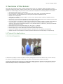
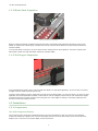

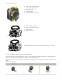


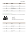
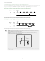

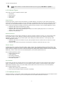

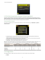
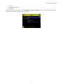


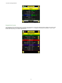

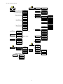


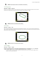
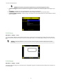


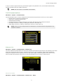

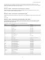

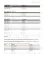


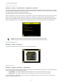
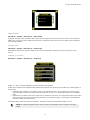


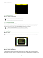
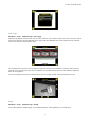
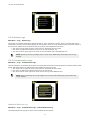

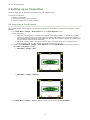


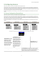


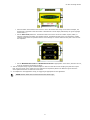

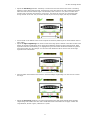


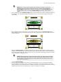
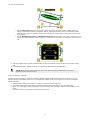


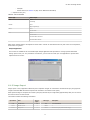

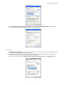

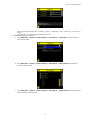

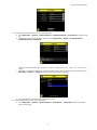
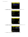
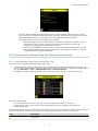
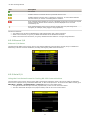
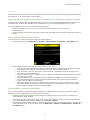
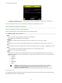


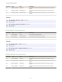


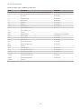


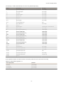


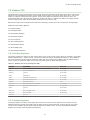


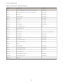


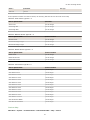


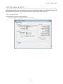


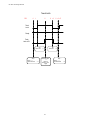

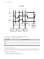


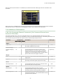


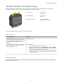
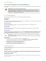
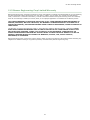


![iVu Plus BCR Gen2 Instruction Manual (Online Only) [ 179047 ]](http://vs1.manualzilla.com/store/data/005859145_1-6c6bbc2cdc90a8f85e92b64ee4999fc2-150x150.png)