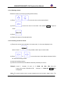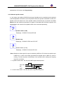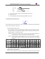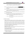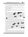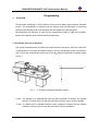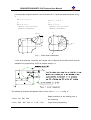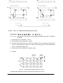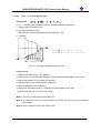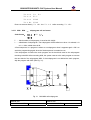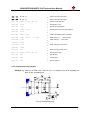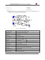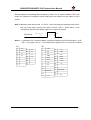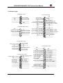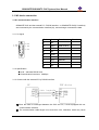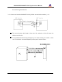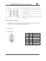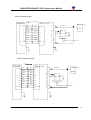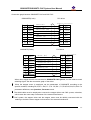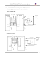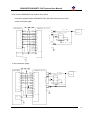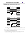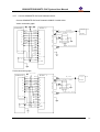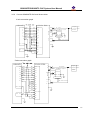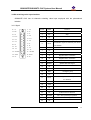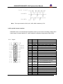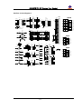
1
GSK928TE/GSK928TC Turning Machine CNC System User Manual GSK CNC Equipment GSK928TE/GSK928TC CNC System User Manual Preface Thank you for purchasing GSK928TE/GSK928TC CNC system. For optimum performance and safety, please read this manual carefully. Caution: Improper operation leads to accidents. Before operating the system, please read the manual completely. Before Use: z z Connect the emergency stop button of the system firmly and correctly, otherwise an emergency stop alarm will occur when switch on the system, so that the system cannot work properly. Set the reference point of the program of the system according to the actual mounting position of the tool of the machine that the system controls. The manual is applied to software V3.20 of GSK928TE/GSK928TC CNC system. Read Appendix 3, Appendix 4, and Appendix 5 when using V2.13, V2.23, V3.01 software of GSK928TC CNC system. For convenience, the manual does not distinguish 928TE from 928TC. Chinese version of all technical documents in Chinese and English languages is regarded as final. i GSK928TE/GSK928TC CNC System User Manual Suggestions for Safety For the safety of the system, the operator who operates the system, and the machine, these suggestions must be read before installing and operating the system. Safety instructions indicated in the manual must be followed when operating the system. Do not operate it until the manual is read completely. Follow safety instructions for the machine that the system will control. Do not run the machine until you have completely read both the instructions and this manual. ii GSK928TE/GSK928TC CNC System User Manual Graphic symbol Caution Operation against the instructions may cause the operator serious injuries. Alarm Wrong operation may injure the operator and damage the system. Warning Improper operation may result in damage to the machine, as well its products. Important information Shield Earthing (PE) Encoder Coil of contact or relay Exchange Connecting terminal iii GSK928TE/GSK928TC CNC System User Manual Notice 1. Check before acceptance Warning Inspect the packing box, where the system is kept, for external damages. 2. Delivery and storage Warning Moistureproof measures are needed while the system is delivered and stored. Never climb the packing box, neither stand on it, nor place heavy items on it. Do not put many packing boxes in piles. Take particular care of the front panel and the display of the system. 3. Installation Warning Protect the system from sunlight and raindrops. The shell of the system is not waterproof. Warning Prevent dust, corrosive air, liquid, conductors and inflammable substances from entering the system. Keep the system away from inflammable and explosive substances. Avoid places where there is powerful electromagnetic interference. Install the system firmly, without vibration. 4. Connection Caution Only qualified persons can connect the system or check the connection. No damage to the connecting wires. Do not press or open the cover of the system with power on. Caution The voltage and the polarity of connecting plugs must accord with the manual. Wet hands are dangerous to grasp the plug or the switch. Warning The connection must be proper and firm. The system must be earthed. 5. Debugging Warning Make sure that the parameters of the system is correct before running. No parameter is beyond the setting limit in the manual. 6. Operation Caution Only qualified operators can operate the system. iv GSK928TE/GSK928TC CNC System User Manual Ensure the switch is OFF before connecting the power supply. Warning The operator can not leave the system to work alone. Do not switch on the system until making sure the connection is correct. The emergency stop button is able to disconnect all power supplies when the system breaks down. Do not switch on/off the system frequently. Warning Prevent the system from environmental interference. 7. Troubleshooting Caution Warning Unqualified persons cannot repair the system. After alarms, do not restart the system until the breakdown is fixed. v GSK928TE/GSK928TC CNC System User Manual Safety suggestions for programming 1. Coordinate system Incorrect coordinate system may cause the machine not to work as expected even if the program is correct, which may injure the operator, and damage the machine as well as its tool and workpiece. 2. G00 rapid traverse G00 rapid traverse performs nonlinear motion between its starting point and end point. Make sure that the path for the tool is safe before G00 rapid traverse starts, otherwise the tool, the machine and the workpiece may be damaged, and even the operator injured. 3. The manual introduces in detail all functions of the system, including optional functions and max. controllable ranges, which are subject to change with the machine. If there is any doubt, please read the instruction for the machine. 4. CNC machines depend on CNC systems, but also power voltage cabinets, servo systems, CNC and the operator panels. It is hard to explain all the integrated functions, programming and operation. Do not use integrated instructions not included in the manual until they have been tested successfully. vi GSK928TE/GSK928TC CNC System User Manual Safety suggestions for operation 1. Test the machine without workpieces or tools. Make sure that the machine runs well before it starts to work. 2. Check the input data of the system carefully before operating the machine. Incorrect input data may cause the machine to work improperly, so as to damage the workpiece and the tool, as well injure the operator. 3. Make sure that the input feedrate of the system is suitable for the expected operation. Feedrate has a maximum for each machine, and the amount of the feed rate is subject to change with operation. Choose the maximum according to the instructions of the machine. Improper feedrate leads the machine to work wrongly, so as to damage the workpiece and the tool, as well injure the operator. 4. When tool compensation is needed, check the direction and the amount of the compensation. Improper compensation causes the machine to work wrongly, so as to damage the workpiece and the tool, as well injure the operator. 5. If the machine is to run in Manual Mode, check the current position of the tool and the workpiece, and correctly specify the moving axis, moving direction and the feedrate. Handwheel control with great override, such as 100, may damage the machine and its tool, even injure the operator. 6. If the tool is return to the reference point, make sure that the machine has been equipped with the device to detect the reference point, otherwise, the tool can not reach the reference point, which may damage the machine and its tool, and even injure the operator. vii GSK928TE/TC CNC System User Manual Content Operation 1. Overview…………………………………………………………………………………..1 2. Technical specification………………………………………………………………..2 3. Operation panel………………………………………………………………………….3 4. Operation......................................................................................... 10 4.1 System power on/power off .............................................................10 4.2 CNC system operating mode ............................................................11 4.3 Edit mode .....................................................................................13 4.3.1 Searching directory of part program ............................................16 4.3.2 Creating, selecting, deleting, renaming and copying a part program.17 4.3.3 Inputting/editing content of part program ....................................22 4.4 Jog mode ......................................................................................29 4.4.1 Manual Jog ..............................................................................29 4.4.2 Manual Step.............................................................................30 4.4.3 Manual MPG(handwheel) control .................................................31 4.4.4 Manual feedrate........................................................................33 4.4.5 Manual rapid traverse rate/feedrate.............................................34 4.4.6 Creating a workpiece coordinate .................................................35 4.4.7 Reference point ........................................................................36 4.4.8 Incremental movement of coordinate axis ....................................37 4.4.9 Absolute movement of coordinate axis .........................................38 4.4.10 MDI function ..........................................................................38 4.4.11 Manual spindle control .............................................................39 4.4.12 Manual spindle speed control ....................................................40 4.4.13 Manual coolant control .............................................................42 4.4.14 Manual tool change .................................................................43 4.4.15 Manual toolsetting...................................................................44 4.4.16 Manual reference point return ...................................................47 4.4.17 Manual machine zero return (machine home return) ....................48 4.4.18 Hydraulic chuck control function ................................................49 4.4.19 Hydraulic tailstock control function ............................................51 4.5 Auto mode.................................................................................53 4.5.1 4.5.2 4.5.3 4.5.4 Function keys in Auto mode .......................................................53 Automatic run a part program ....................................................55 Displaying in a part program running ...........................................58 Manual operation of auxiliary function..........................................62 i GSK928TE/TC CNC System User Manual 4.5.5 Override adjust ........................................................................63 4.5.6 Operations in a part program running ..........................................64 4.5.7 Reference point return in Auto mode ...........................................66 4.5.8 Feed hold knob in automatic run .................................................66 4.6 Parameter setting...........................................................................68 4.6.1 Parameter specification..............................................................68 4.6.2 Parameter input........................................................................77 4.6.3 Parameter initialization ..............................................................78 4.6.4 Searching and modifying each bit definition of bit parameter...........79 4.7 Tool offset setting mode ..................................................................80 4.7.1 Searching a tool offset value ......................................................81 4.7.2 Inputting a tool offset by keyboard..............................................81 4.8 Diagnosis ......................................................................................84 4.8.1 Diagnosis definition of input interface ..........................................84 4.8.2 Diagnosis definition of output interface ........................................85 4.8.3 Encoder — spindle encoder and spindle rotating test ....................86 4.8.4 Auxiliary function control of machine ...........................................87 4.9 Alarm of emergency stop and overtravel............................................88 4.9.1 Emergency stop........................................................................88 4.9.2 Overtravel switch alarm .............................................................89 4.9.3 Driver alarm ............................................................................89 4.9.4 Other alarms............................................................................89 4.10 LCD brightness adjust ...................................................................90 4.11 Driver switch control .....................................................................90 Programming 1. Overview........................................................................................ 91 1.1 Coordinate axis and its direction.......................................................91 1.2 Machine zero .................................................................................92 1.3 Programming coordinate .................................................................92 1.3.1 Absolute coordinate value ..........................................................92 1.3.2 Incremental coordinate value .....................................................92 1.3.3 Compound coordinate value .......................................................93 1.4 Workpiece coordinate system ...........................................................93 1.5 Reference point..............................................................................94 2. Program structure.......................................................................... 94 2.1 Character ......................................................................................94 2.2 Word ............................................................................................96 2.3 Block number ................................................................................96 2.4 Block ............................................................................................96 2.5 Program structure ..........................................................................97 3. Codes and their functions .............................................................. 97 3.1 G codes — preparatory function .................................................97 ii GSK928TE/TC CNC System User Manual 3.1.1 G00 — rapid traverse movement .............................................98 3.1.2 G01 — Linear interpolation ................................................... 100 3.1.3 G02 G03 — Circular interpolation......................................... 100 3.1.4 G33 — thread cutting .......................................................... 104 3.1.5 G32 — tapping cycle in Z direction......................................... 107 3.1.6 G50 — create a workpiece coordinate system.......................... 108 3.1.7 G26 — reference point return ................................................. 109 3.1.8 G27 — reference point return in X direction ............................ 110 3.1.9 G29 — reference point return in Z direction ............................ 110 3.1.10 G04 — dwell ..................................................................... 110 3.1.11 constant surface speed on/off—G96/ G97 ................................. 111 3.1.12 Single canned cycle ............................................................... 112 3.1.13 Compound cycle ................................................................... 124 3.1.14 G22 G80 — part of program cycle..................................... 128 3.1.15 G93 — system offset ........................................................ 130 3.1.16 G98 - feed per minute .................................................... 130 3.1.17 G99 - feed per rev.......................................................... 131 3.2 M function 3.2.1 M00 — 3.2.2 M 02 — 3.2.3 M20 — 3.2.4 M30 — — auxiliary function ............................................... 131 pause .................................................................... 133 end of program...................................................... 133 end of program and machining cycle .......................... 133 end of program,spindle stop and coolant OFF ............ 133 3.2.5 M03 M04 M05 — spindle control ....................................... 133 3.2.6 M08 M09 — coolant ON/OFF.............................................. 134 3.2.7 M10 M11 — workpiece clamped or unclamped ..................... 134 3.2.8 M41 M42 M43 — spindle automatic gear shifting control ...... 135 3.2.9 M78 M79 — tailstock going forward and retreating backward . 135 3.2.10 M97 — program skip ........................................................ 135 3.2.11 M98 M99 — subprogram call and return ............................ 136 3.2.12 M21 M22 M23 M24 — user output control ...................... 137 3.2.13 M91 M92 M93 M94 — user input................................... 138 3.3 S function — spindle function.................................................... 139 3.3.1 Multi-gear motor control .......................................................... 139 3.3.2 Inversion frequency control ...................................................... 140 3.4 T function — tool function ........................................................ 140 3.4.1 Tool Offset mode — traverse the slider of machine ................... 141 3.4.2 Tool Offset mode — redefine system coordinate ..................... 142 3.5 F function — feedrate function .................................................. 142 4. Programming rules .......................................................................144 4.1 Some codes in one block ............................................................... 144 4.2 Modal and initial state of code ........................................................ 145 4.3 Other rules.................................................................................. 145 4.4 Programming example .................................................................. 145 4.4.1 Outer machining ..................................................................... 145 iii GSK928TE/TC CNC System User Manual 4.4.2 Thread machining example ...................................................... 147 4.4.3 Compound machining .............................................................. 150 4.5 Alarm list .................................................................................... 154 Appendix 1:GSKTR communication program specification ................157 Appendix 2:GSK928TE CNC System software version specification ...159 Appendix 3:GSK928TE CNC System V2.13 software specification .....161 Appendix 4:V2.23 version of GSK928TE CNC System specification....163 Appendix 5:V3.12 version software of GSK928TE CNC System specification .......................................................................................165 Appendix 6:V3.20 FLASH chip copy and verification..........................167 Connection 1. Interface overview .........................................................................168 1.1 Interface layout ........................................................................... 168 1.2 Total frame.................................................................................. 169 1.3 Total connection graph .................................................................. 170 2. Interface function...........................................................................171 2.1 Specification ................................................................................ 171 2.2 Interface graph ............................................................................ 172 3. CNC device connection....................................................................173 3.1 X1 communication interface........................................................... 173 3.3 X3 spindle encoder interface .......................................................... 176 3.4 X4 toolpost interface..................................................................... 178 3.5 X5 feed driver interface................................................................. 180 3.6 X6 switching value input interface................................................... 191 3.7 X7 switching value output.............................................................. 195 3.8 X7 spindle inverter interface .......................................................... 198 Appendix 1 Toolpost controller circuit diagram ..................................200 Appendix 2 Interface circuit diagram .................................................201 Appendix 3 Machine zero return mode..............................................204 Appendix 4 External control connection graph..................................206 Appendix 5 GSK928TE CNC integrated wiring diagram .......................207 Appendix 6 GSK928TE CNC contour and installation diagram .............209 iv GSK928TE/GSK928TC CNC System User Manual Operation 1. Overview With 320×240 lattice graphic LCD, GSK 928TE CNC system takes as key control the high-speed CPU and the complex programmable logic device of super-large-scale integrated circuits. ISO CNC code is employed to write part programs. The system is characterized by µ-level precision control, a full screen editing, Chinese operation interface, real time demonstration of the machining process, and high cost-performance ratio. By means of programming, the system can be used to control stepper motors, so as to machine outer cylinders, end faces, grooves, tapers, circular arcs, and threads. 1 GSK928TE/GSK928TC CNC System User Manual 2. Technical specification 2.1 Controlled axes 2 (X, Z axis) 2.2 Link axes 2 (X, Z axis) 2.3 Min. setting unit 0.001 mm 2.4 Min. motion unit X: 0.0005mm; Z: 0.001mm 2.5 Max. dimension for programs ±8000.000 mm 2.6 Max. traverse rate 15000 mm/min 2.7 Feedrate 5-6000 mm/min (G98/G99) 2.8 Capacity of part program 24KB 2.9 Max. number of part programs 100 2.1 Graphic LCD 320×240 lattice 2.11 Communication interface Standard RS-232 2.12 Tool selection 4(up to 8) 2.13 Compensation Tool compensation, clearance compensation 2.14 MPG(handwheel) ×0.001 ×0.01 ×0.1 S1, S2, S3, S4 direct output; S0~S15 output 2.15 Spindle with BCD code; three automatic gear shifting with 0~10V analog output; 1024p/r, 1200p/r spindle encoder available 2.16 G codes 24 codes,including the fixed /compound cycles, threading in Z direction Metric/inch single and multiple straight, taper 2.17 Thread functions thread, high-speed retraction with setting the retraction distance 2 GSK928TE/GSK928TC CNC System User Manual 3. Operation panel DRY G M X Z 7 8 9 S T U / W E 4 5 6 F I P K N 1 2 3 D L R . 0 - SINGLE EDIT X CW STOP STEP JOG DELETE ENTER INPUT AUTO X X X MPG CCW Z Z H/L COOLANT ESC TOOL PAUSE Z Z MPG RUNNING 3.1 LCD:CNC man-machine dialogue interface with a resolution 320×240 lattice. 3.2 Number keys:Input all kinds of data(0-9). 3.3 Address keys:Input English letters in word addresses of part programs. 3.4 Function keys:All function keys are based on Numerical Control of Machine-Symbol. Increasing rapid traverse override: Increase rapid traverse override in “Jog” mode and G00 rapid traverse override in “Auto” mode. Reducing rapid traverse override: Reduce rapid traverse override in “Jog” mode and G00 rapid traverse override in “Auto” mode. 3 GSK928TE/GSK928TC CNC System User Manual Increasing feedrate override: Increase feedrate override in “Jog” mode and G01 feedrate override in “Auto” mode. Reducing feedrate override: Reduce feedrate in “Jog” mode and G01 feedrate override in “Auto” mode. X Reference point return in X direction: It is valid in “Jog” /“Auto” mode. Z Reference point return in Z direction: It is valid in “Jog”/“Auto” mode. X Machine zero return in X direction: It is valid in “Jog”/“Auto” mode.(whether machine zero is valid is defined by MZRO bit of P12 ). Z Machine zero return in Z direction: It is valid in “Jog”/ “Auto” mode.(whether machine zero return is valid is defined by MZRO bit of P12) DRY Dry run: In “Auto” mode, Dry run tests a program without G, S, M, and T functions output. In “Edit” mode, Dry run moves the cursor directly to the first character behind the block number. 4 GSK928TE/GSK928TC CNC System User Manual SINGLE Single/(Continuous) Run: Single block/(Continuous) run in “Auto” mode EDIT Edit mode JOG Jog mode AUTO Auto mode Parameter mode Offset mode Diagnosis mode 3.5 Edit /states selection key Switch the input mode in “Edit” mode — Insert/Rewrite . DELETE Delete a digit, a letter, a block or a program in “Edit” mode. 5 GSK928TE/GSK928TC CNC System User Manual ESC Cancel current data input or escape from current operating mode. INPUT Input all kinds of data or select a required program to edit or execute and create a new part program. ENTER Confirm it. Page Up:Page up to search programs or parameters in “Edit”/” Parameter”/” Offset” mode, and LCD highlight will increase in other modes. Page Down:Page down to search programs or parameters in “Edit”/”Parameter”/ “Offset” mode, and LCD highlight will increase in other modes. Cursor Up:The cursor moves up one block in “Edit”/”Parameter”/” Offset” mode. Cursor Down:The cursor moves down one block in “Edit”/”Parameter”/ “Offset” mode. Cursor left:The cursor left moves one character in “Edit” mode. Cursor right:The cursor right moves one character in “Edit” mode. 6 GSK928TE/GSK928TC CNC System User Manual 3.6 Cycle start and feed hold button Start and pause programs in “Auto” mode. RUNNING PAUSE 3.7 Cycle start key: Start to run programs in “Auto” mode. Feed hold key: Motor reduces to pause in “Jog” or “Auto” mode. Manual axis control key The selected axis and its direction in “Jog” mode: Traverse in X negative direction. Traverse in X positive direction. Traverse in Z positive direction. Traverse in Z negative direction. Rapid traverse/ feed key Switching rapid traverse and feed. 7 GSK928TE/GSK928TC CNC System User Manual Manual Step Selecting each step width or MPG(handwheel) feed in “Step”/ “Handlwheel” mode. X X MPG MPG(handwheel) in X direction The motion in X direction is controlled by the MPG(handwheel) (when the control is valid, other control keys related to the axis moving are invalid) . Z Z MPG MPG(handwheel) in Z direction The motion in Z direction is controlled by the MPG(handwheel) (when the control is valid, other control keys related to the axis moving are invalid). SINGLE Step/Jog mode Switch “Step”/”Jog” mode. 3.8 Manual tool change and auxiliary function keys Select directly the next tool number and control the machine to complete auxiliary functions as follows: CW Spindle rotation (CW) Spindle rotates (CW).(observe from the axial of motor) STOP Spindle stops Spindle stops. 8 GSK928TE/GSK928TC CNC System User Manual CCW Spindle rotation (CCW) Spindle rotates (CCW).(observe from the axial of motor) COOLANT Coolant control Coolant ON/OFF H/L Spindle gear shifting Select the speed of each gear when the machine is equipped with multi-gear (up to 16 gears) spindle motor and control loops. TOOL Tool change Select the next tool number neighboring to the current one. Note:The above-mentioned pressing keys are valid in “Jog”, “Auto” and “Diagnosis” mode when the tool does not traverse in X, Z direction, but only coolant control is valid when the tool traverses. 3.9 Reset key System reset key When the system resets, the tool stops in X and Z direction, the auxiliary function outputs are invalid, and the machine stops and returns to the initialization. 3.10 State indicator It indicates the current state of CNC system. There are 15 function keys with LED indicator. When LED ON, its function of corresponding key is valid, otherwise it is invalid. 9 GSK928TE/GSK928TC CNC System User Manual 4. Operation This chapter introduces operations of GSK928TE CNC system. Please read carefully before operation. 4.1 System power on/power off GSK928TE CNC system is not equipped with the system power switch. User installs it according to the different machine to avoid bad effects to CNC system owing to the impaction of power supply. CNC system power on as follows: 1. Power on the power switch. 2. Connect with the power switch of CNC. The CNC will display the initial window as Fig. 1. In the course of displaying, the system displays the software version number by and enters the normal pressing other keys persistently except for operating mode after the keys are released. CNC system power off as follows: 1. Power off the power switch of CNC system. 2. Power off the power switch of machine. Note:If the system powers on firstly, the operations are as follows: 1. The initialization operations of parameter are as follows: ① For initializing 928TE, press down same time, then release and the number key “9” at the and the number key “9” later, and so the system has completed the initialization. 10 GSK928TE/GSK928TC CNC System User Manual DELETE ② For initializing 928TC, press down and at the same time, DELETE then release , after three second , so the system has completed the initialization. At this time, all offset parameters are zero and parameters of machine are set to internal setting values of CNC system. See Section Operation, Offset and Parameter mode. 2. Measure the backlash of machine in X, Z direction,and input their values to the machine parameters P07 and P08. For input methods, see Section Operation, Parameter mode 3. Set DIRZ and DIRX bit of P11 according to the electric circuit design and the motor’s direction of machine. 4. Adjust parameters P05, P06,P17~P22 according to the load of machine, which make it run efficiently and stably. 广 州 Fig. 1 数 控 Initial window 4.2 CNC system operating mode GSK928TE CNC System is employed with operating mode keys to select directly the operating mode, which is helpful to directly change operating modes, easy, convenient and direct operations. After GSK928TE CNC System is switched on, the dynamic display window is the above Fig. 1. The window is displayed circularly. Press down any keys except for , the 11 GSK928TE/GSK928TC CNC System User Manual system will enter the operating mode which is that of last power off. Press down ESC ESC to start up or and at the same time, and then ESC release and later , and so the system will enter “Jog” mode. 12 GSK928TE/GSK928TC CNC System User Manual 4.3 Edit mode In “Edit” mode, the user manually inputs or modifies the content of part program by operation panel. In “Edit” mode, create, select and delete part programs by keyboard, and insert, modify and delete the content of selected part program. Besides, transmit part programs of the system to the external PC or the edited part programs of external PC to CNC system by the serial connection between RS232 communication interfaces and general-purpose PC. EDIT to enter “Edit” mode, the system displays program names of all After pressing part programs stored in the current program, the byte amount contained in current program and the available memory bytes of system. See Fig. 2: GSK %00 EDIT %02 %03 PROG. AMOUNT:05 EDIT MANUAL 0223 %04 %10 FREE BYTES: AUTO Fig. 2 %02 PARA OFFT 15750 DIAG Edit mode Edit keys in Edit mode (1) Cursor up key The cursor moves to the first character behind the block number of the upper block when the key is pressed once. The key being pressed down, the cursor sequentially moves up till the first block of block or the key is released. (2) Cursor down key 13 GSK928TE/GSK928TC CNC System User Manual The cursor moves to the first character behind the block number of the next down block when the key is pressed once. The key being pressed down, the cursor sequentially moves down till the last block number of block or the key is released. Cursor left key (3) The cursor moves left one character when the key is pressed once. The key being pressed down, the cursor sequentially moves left till the first character of block or the key is released. Cursor right key (4) The cursor moves right one character when the key is pressed. The key being pressed down, the cursor sequentially moves right till the last character of block or the key is released. Note: Cursor — prompt identifier to indicate the current editable character position. There are two states of CNC system. A. The cursor is displayed to a horizontal line under a character in Insert mode. B. The cursor is displayed to the pointed character in inverse and highlight. The two cursors can be switched by . DRY (5) Dry run key The cursor moves to the head of block or the head of first word of this block by pressing continuously. . 14 GSK928TE/GSK928TC CNC System User Manual STEP (6) Step/Jog mode The cursor moves to the behind of the last character of this block. (7) Insert/rewrite key Switch Insert/Rewrite mode once when the key is pressed once, and the cursor will change correspondingly. The cursor in Insert mode is a flashing horizontal line, but that in Rewrite is a character in flashing highlight. INPUT (8) Input key When the key is pressed once, the program number with 2-digit is input to create a new program, select or delete the existing program and all programs. (9) Page up Search the program number and display the content of previous page. (10) Page down Search the program number and display the content of next page. (11) U / , W E , I P , K N , D L , R Double functions key 15 GSK928TE/GSK928TC CNC System User Manual Each key has two definitions. Pressing it once is the first definition value,namely, U W I K D R. The same key is pressed again, the system will automatically rewrite the previous input value into the second definition value, namely / E P N L . If the same key is pressed continuously, the input value will be switched between the first definition value and the second one. ‘/’ is the skip block character, ‘ ’is the space character. 4.3.1 Searching directory of part program In “Edit” mode, the system displays the program name list of all part programs, all part program amount and the leftover bytes in the part program memory area of CNC system. EDIT Press EDIT ESC in “Edit” mode or press or when editing programs as Fig. 3: GSK EDIT %02 %00 %02 %03 PROG. AMOUNT:05 %04 0223 %10 FREE BYTES: 15750 EDIT MANUAL AUTO PARA OFFT DIAG Fig. 3 Searching a part program catalog / creating, selecting and deleting part programs 40 program names are displayed in each screen. When part programs in memory area are over 40, they are displayed by paging. Press number list of next page and press to display the program to display again the program number list of first page till the last page. 16 GSK928TE/GSK928TC CNC System User Manual 4.3.2 Creating, selecting, deleting, renaming and copying a part program The above-mentioned operations can be executed in the state of catalog search of part program or in the course of editing program content. INPUT is pressed in the state of catalogue search The system displays as Fig. 4 when of part program. 4.3.2.1 Creating a new part program INPUT in the state of catalog search of part program. (1) Press (2) Input a new program number which does not exist in the program catalog list with 2-digit by keyboard. See Fig. 4. (3) Press Enter . (4) After part programs are created, the system will automatically enter “Edit” mode. INPUT Example: Creating %20 program: to input Press 2 0 and press Enter . So the program has been created to enter “Edit” mode of %20 program. See Fig. 5: GSK EDIT %02 %00 PROG. NO. %20 PROG. AMOUNT 05 %02 %03 GSK %04 %10 N0000 EDIT %20 0007 _ Enter FREE BYTES 15750 EDIT MANUAL AUTO PARA Fig. 4 0223 OFFT DIAG Inputing a program number. Fig. 5 Creating a new program 17 GSK928TE/GSK928TC CNC System User Manual 4.3.2.2 Deleting a part program INPUT in the state of catalog search of part (1) Press program. (2) Input the required program number by keyboard. DELETE and the system will display (3) Press (4) Press Enter CONFIRM ?. to delete the part program which program number has been input; press any keys to cancel the deletion. INPUT Example: Deleting %03 to input program: press 0 , 3 in turn, and DELETE press and Enter, so the program is deleted as Fig. 6: GSK EDIT %00 %02 %03 %02 %04 0223 %10 PROG. NO. %03 SURE ? PROGRAM AMOUNT 05 FREE BYTES 15750 EDIT MANUAL AUTO PARA Fig. 6 OFFT DIAG Deleting a part program 4.3.2.3 Selecting a part program INPUT (1) Press in the state of catalog search of part program. (2) Input the required program number by keyboard. (3) Press Enter . (4) The part program is selected completely and the system displays its content to enter 18 GSK928TE/GSK928TC CNC System User Manual “Edit” mode. INPUT to input Example: Selecting %01 part program. Press press 0 1 and then Enter , so the selection is completed. See Fig. 7: GSK EDIT %01 N0000 N0010 N0020 N0030 N0040 G0 G1 G0 G4 M20 0082 X0 Z0 X4.80 Z9.6 F500 X0.0 Z00 D2 Fig. 7 Selecting a part program Note 1:After the first power on, the system enters “Edit” mode or there is no content in the memory area of part program, it will automatically create and select %00 program. The system will consider %00 as the current program after it be initialized. Note 2: After the system has selected one program, the required one is changed only by selecting it. Even if the system powers off, the selected program number cannot be changed once it is selected. 4.3.2.4 Outputting a part program Output part programs from CNC system internal memory to the external computer. (1) Connect the communication cable between CNC system and the computer when power off. (2) After CNC powers on, select “Edit” mode. (3) Select the required part program according to Section Operation, 4.3.2.3 Select a part program (do not select it if the current program is to be sent). (4) Press W , and the system prompts READY TO SEND !. (5) Keep the computer in the state of waiting for the receiving(See appendix 1 GSKTR communication program specification). (6) After the computer is ready, if SENDING … Enter is pressed, the system will prompt ,and so the system sends the selected program to the computer. 19 GSK928TE/GSK928TC CNC System User Manual (7) After the sending has completed, the system prompts DONE ! , and any keys are pressed to return to “Edit” mode. ESC (8) Press to pause the sending. 4.3.2.5 Inputting a part program Input the stored part program from the external PC to CNC system. (1) Connect the communication cable between CNC system and the computer when power off. (2) After CNC system powers on, select “Edit” mode. (3) Press (4) R and the system prompts READY TO RECEIVE!. Keep the computer in the state of output. (See Appendix 1 GSKTR communication program specification ). (5) After the system is ready, if RECEIVING … (6) Enter is pressed, the system will prompt , and so the system sends the selected program to the CNC system. After the receiving is completed ,the system prompts DONE ! and returns to “Edit” mode if any keys are pressed. The system displays the input program name in the catalog list of part program. DELETE (7) Press to interrupt the receiving. Note 1: In the course of inputting part program, CNC system considers the character string “% XX” contained in the first block of the sent program from the computer as the program name to save. If the sent program name is the same as one in CNC system, the system cannot display the program name content of the sent program name, and will display it if the old one is deleted. Note 2: Send/receive part programs between 2 GSK928TE CNC systems according to the above–mentioned methods. 2 CNC systems separately operate according to part program input/output ways. 20 GSK928TE/GSK928TC CNC System User Manual Note 3: It must have the block number of part program when the part program is sent from PC to CNC system, otherwise there is a mistake. 4.3.2.6 Deleting all part programs Delete all programs once in the program memory area of CNC system. INPUT ⑴ Press ⑵ Input in the state of catalog search of part program. — , O by keyboard. DELETE ⑶ Press ⑷ Press ,and the system prompts Enter CONFIRM ? to delete all part programs. Press other keys, and the system does not execute the deletion and returns to “Edit” mode. 4.3.2.7 Renaming a part program Rewrite the current program name to another one. INPUT ⑴ Press , and the system displays % . ⑵ Input the program name which does not exist in the program name list, and press to rewrite the current program name to the input program name. Example: Rename the current program name %00 to %05. INPUT Press to input 0 5 , and press , so the renaming is completed. 21 GSK928TE/GSK928TC CNC System User Manual 4.3.2.8 Copying a part program Copy the content of current program to another new one and consider it as the current one. INPUT ⑴ Press , and the system displays % . ⑵ Input a program name which does not exist in the program name list, and press INPUT to copy all contents of current program to the program whose number is input. The new program name becomes the current one. Example: Copy program of current program name %00 to that of %05. INPUT Press INPUT to input 0 5 , and press , so the copy is completed. Note: If the input program name exists, the system will prompt REPEAT PROG. NO. . At the moment, press any keys to input again the program name which does not exist in the program area, and then press Enter, So the copy is completed. 4.3.3 Inputting/editing content of part program CNC machining is defined that the system automatically completes the machining of workpiece according to the part program sequence input by user. Each program is composed of many blocks and each block consists of a block number, codes and data. Start the machine and gain the standard workpiece after inputting the part program content according to the technology flow. “Edit” mode of CNC system is employed with the full-screen and part programs are employed with the file management mode. 22 GSK928TE/GSK928TC CNC System User Manual 4.3.3.1 Automatic creating a block number Each part program contains many blocks and each block begins with the block number “ N**** ”; After a new program is created, the system will automatically generate the first block number“ N0000 ”; After one block is input and Enter is pressed, the system will generate the next block number. In the course of input, the increment of block number is defined by P23. When a block is inserted, the system will automatically consider the 1/4 integer value of P23 as the increment to generate the block number. When M98, M97, M91, M92, M93, M94 and others codes related with the block number are executed, there are no repetitive block numbers in the program, otherwise the system will alarm. If the above codes are not executed, the block number can be repeated. See Fig. 8 for a program generation and inserting a block number in a block (P23 value is 10). GSK N0000 N0010 N0020 N0030 N0040 EDIT %01 G0 G1 G0 G4 M20 0082 X0 Z0 <Enter> X4.8 Z9.0 F500<Enter> X0.0 Z0.0 <Enter> D2 <Enter> <Esc> Fig. 8 Automatically generating block number and inputting program content Note: The system will not display Enter and Esc in the screen. 4.3.3.2 Inputting content of program “Edit” mode of CNC system is employed with the full screen. Inputting content of program is executed in “Edit” mode. (1) Create a new program according to the creating method of new part program. (2) After the block number N0000 is displayed, input the content of one block by keyboard. (3) Input completely one block and then press Enter . (4) The system will generate the sequence number of next block and the content of program should be input continuously. (5) Input completely the last block and press Esc to end the input of content of program . (6) The cursor rapidly moves in the block. 23 GSK928TE/GSK928TC CNC System User Manual DRY Press once, and the cursor will point to the head of word; press it again, and the cursor points to the head of block, and the above steps are executed circularly. STEP Press (7) once, the cursor points to the end of block. Insert a block in the first block. Move the cursor to the head of the first block and then press Enter . Note: Only 40 characters can be displayed in each block, and only previous 40 can be displayed if exceeding the limit. Press → to retract left one character. There are 255 characters at most in one block, otherwise the system will not accept the next input. Only 13 blocks in each screen can be displayed and the cursor will automatically move up when exceeding the limit. 4.3.3.3 Inserting a block Insert one or more blocks between two blocks. to move the cursor to the first one of two blocks. (1) Press to move the cursor to the behind of last character, or press (2) Press STEP to move directly the cursor to the behind of last character. (3) Press Enter , and the system will generate a new block number between two blocks (the increment of sequence number is 1/4 integral value of P23 , and if there is not enough, the block number of the next block is rewritten.) and blank one block. (4) Input the content of required block. 24 GSK928TE/GSK928TC CNC System User Manual (5) After the content is input, Enter is pressed to insert blocks. When only one block is inserted, the operation is not executed. (6) The inserting is completed. DRY (7) If the block is inserted before the first block, is pressed to move the cursor to the under “N” of the first block, and the system will generate a new block number before the first block after Enter is pressed. Note:After one block is inserted behind the last block and Enter is pressed, the system will automatically generate the next block number. Example:Insert a new block M3 between N0020 and N0030 in Fig. 8 as follows: (1) Press to move the cursor to N0020 , and press STEP to move the cursor to the behind of Z0.0. (2) Press Enter , and the system will automatically generate one block number and blank a block to display N0022 as Fig. 9. The cursor points to the first input character of the new block. (3) Input M 3. (4) The inserting is completed as Fig. 10. GSK N0000 N0010 N0020 N0022 N0030 N0040 EDIT %01 0089 G0 X0 Z0 G1 X4.80 Z9.6 F500 G0 X0.0 Z0.0 <Enter> __ G4 D2 M20 Fig. 9: EDIT %01 0091 G0 X0 Z0 G1 X4.80 Z9.6 F500 G0 X0.0 Z0.0 M 3 G4 D2 M20 Fig. 10: create a new block number after GSK N0000 N0010 N0020 N0022 N0030 N0040 Input and end the insertion Enter is pressed 25 GSK928TE/GSK928TC CNC System User Manual 4.3.3.4 Deleting a block Delete all content in one block (including block number). to move the cursor to the required block. (1) Press (2) Press to move the cursor to the under of the address N of required block. DELETE (3) Press . (4) Delete all content of the selected blocks. 4.3.3.5 Inserting a word in a block (1) Ensure the current input operation is in Insert mode, i.e. the cursor displays to the is not pressed, switch Input to Insert mode. under of block. If (2) Press or to move the cursor to the address character behind the required inserting position. (3) Input the inserting content. (4) Insert the content before the address character pointed by the cursor. Example:Insert 1 between X and 0 cursor to the under of O behind of X of N0020 ,and input G0 X0.0 Z0.0. Move the 1 . N0020 G0 X10.0 Z0.0 is displayed. Note:The system requires there is a space between each word (a letter +digit) in block. The 26 GSK928TE/GSK928TC CNC System User Manual system can automatically judge and generate a space in the course of inputting when the program is edit, but cannot automatically judge in the course of inserting, and so the user will input the space to ensure the complete program. 4.3.3.6 Deleting a word in a block Delete the invalid content. to move the cursor to the required address character. (1) Press DELETE (2) Press to delete the address character. 4.3.3.7 Modifying a word in a block Adopt two methods to modify an address character of block according to the input mode (Insert/Rewrite). Insert mode: use the insert and the delete methods together. ,move the cursor to the required address character. (1) Press (2) Input the new word. (3) Delete the invalid word according to the operation of deleting the content of block. Rewrite mode: modify the character where the cursor points. (1) Press to switch to Rewrite mode (the cursor pointing to the address character in highlight square). (2) Press to the required address character. 27 GSK928TE/GSK928TC CNC System User Manual (3) Input the new address character, and the cursor points to the next one. Example:Rewrite X of N0020 G0 X0.0 Z0.0 to U . (1) Switch to Rewrite mode. (2) Move the cursor to the under of X . (3) Input U. The end is :N0020 G0 U 0.0 Z0.0. 4.3.3.8 Skipping a block Add / before the block number N of block, and the system will skip the block to execute the next one when executing the program. (1) Switch to Insert mode. to move the cursor to the (2) Move the cursor to the required block and press under of the block number N (3) Sequentially press time, insert / U/ before of block. two times: the first time, insert U before N ; the second N. 28 GSK928TE/GSK928TC CNC System User Manual 4.4 Jog mode In “Jogl” mode, the motion of slider, the starting/stopping of spindle, coolant ON/OFF, manual tool change, the reference point return and the machine zero return in X, Z direction, and other functions can be completed by operating the keyboard. When the CHCD bit of P11 is set to 1, the actual spindle speed can be displayed real time; when CHCD bit of P11 is set to 0, the programming spindle speed is displayed. When the machine is equipped with the hydraulic chuck and the tailstock, the system can control the operation of the hydraulic chuck and the tailstock by a pedal switch or external keys. They keep interlock between the hydraulic chuck, the tailstock and the spindle. JOG Press to enter “Jog” mode. There are Manual JOG mode and Manual Step STEP mode. The initial mode is Jog. Press to switch between “Jog” mode and “Step” mode. If the system is equipped with the MPG(handwheel), the system can adopt MPG(handwheel) control mode. “Jog” mode. is as follows: GSK MANUAL JOG X Z 0090.000 0125.000 F. OVERRIDE 100% SPINDLE STOP R.OVERRIDE 100% SPEED 0000 COOLANT OFF TOOL 1 OFFSET 0 EDIT MANUAL AUTO PARA OFFT DIAG Fig. 11 Jog mode 4.4.1 Manual Jog In “Jog” mode, press down a manual feed direction key, and the slider will continuously traverse along the selected axis and direction. The slider will stop once the key is released. The traverse rate will be executed according to the selected rapid traverse rate or feedrate. 29 GSK928TE/GSK928TC CNC System User Manual Meanings of manual feed direction keys in “Jog” mode are as follows: X: manual feed negative direction key X: manual feed positive direction key Z: manual feed negative direction key Z: manual feed positive direction key Note 1: Press the feed key in “Jog” mode, and the slider will traverse when the external spindle and the feed hold knob are permitted to feed; press the manual feed key, and the slider does not traverse in the state of feed hold. Note 2: Even though the feed key is released, because the system automatically accelerates/decelerates, the slide will continuously traverse not to stop when the motor runs rapidly. The actual moving distance is determined by max. speed of the motor, the acceleration/deceleration time and the feedrate override. The more the acceleration /deceleration time is and the rapider the speed is, the longer the moving distance of motor decelerating is, otherwise the moving distance is shorter. 4.4.2 Manual Step In “Step” mode, the moving distance of slider each time is preset. The slider will traverse one setting step in the selected coordinate axis and its direction when the manual feed direction key is pressed once. When the key is pressed down, the slider feeds as one step until the last step after it is released. Manual Step feed mode as Fig. 12: 30 GSK928TE/GSK928TC CNC System User Manual GSK MANUAL STEP X Z 0090.000 0125.000 F. OVERRIDE 100% R.OVERRIDE 100% COOLANT OFF EDIT MANUAL AUTO Fig. 12 SPINDLE STOP SPEED 0000 TOOL 1 OFFSET 0 PARA OFFT DIAG Manual step feed mode Its step size is divided into 7 grades: 0.001 0.01 0.1 1.0 10.0 50.0 to select each step size. The step size degrades one grade if it is Press pressed once. It returns to the first grade after the last one is selected. Note 1: In “Step” mode, press PAUSE to stop slider traversing. When the key is pressed down, the slider stops and the unfinished step will not be reserved, and then the feed key is pressed to execute the next step feed. The step size is the moving distance in diameter in X direction. Note 2: When the manual feed key is pressed, the external spindle and the feed hold knob are permitted to feed, the slider traverses. When the manual step feed key is pressed, the slider does not traverse in the state of feed hold. Note 3: When the slider is traversing and the feed hold knob rotates to the feed hold position, the slider will decelerate to stop and the unfinished step size will not be reserved. 4.4.3 Manual MPG(handwheel) control In “MPG(handwheel)” mode, the micro motion of slider is controlled by rotating the manual 31 GSK928TE/GSK928TC CNC System User Manual X pulse generator (MPG(handwheel)). Press X MPG Z or Z MPG to enter “MPG(handwheel)” mode and select the coordinate axis controlled by the MPG(handwheel) at the same time. See Fig. 13 (taking X axis as example). MANUAL HANDWHEEL GSK X Z X 0.001 0000.000 0000.000 F. OVERRIDE 100% SPINDLE STOP R.OVERRIDE 100% SPEED 0000 COOLANT OFF TOOL 1 OFFSET 0 EDIT MANUAL AUTO PARA OFFT DIAG Fig. 13 MPG(handwheel) control z Rotate the MPG(handwheel) after selecting the required coordinate axis to traverse. The selected axis will traverse along with the MPG(handwheel) rotating. The MPG(handwheel) rotates (CW), the axis traverses positively. The MPG(handwheel) rotates (CCW), the axis traverses negatively. z There are three gears for each motion amount of handwheeel: 0.001, 0.01, 0.1mm. Press to switch among them. The system will automatically select 0.1 mm when the previous step size exceeds 0.1 from “Step” mode to “MPG(handwheel)” mode. Note 1: The speed of MPG(handwheel) should be lower than 5 rev/s, otherwise the motor still traverses even if the MPG(handwheel) has stopped, which causes the moving distance does not correspond with the scale. Note 2: In “MPG(handwheel)” mode, all the functions related to the axis moving including Jog, reference point return, incremental/absolute movement are invalid, but S, M, T and other auxiliary functions are valid. 32 GSK928TE/GSK928TC CNC System User Manual Note 3: Even if the MPG(handwheel) is shaken, the slider does not traverse when the external spindle and the feed hold knob forbid the slider to traverse. The spindle speed cannot be changed real time. Note 4: When the bigger override (X 100) is selected, the motor will rapidly traverse if the MPG(handwheel) is rotated rapidly. At the moment, because the system automatically accelerates/ decelerate, the motor will traverse not to stop although the MPG(handwheel) stops. The actual moving distance is determined by max. speed of motor, the acceleration/ deceleration time, the feedrate override and the MPG(handwheel) speed. The rapider the speed is, the longer the acceleration/deceleration time is and the rapider the MPG(handwheel) speed is, the longer the moving distance of motor decelerating is, otherwise the shorter the moving distance of motor is. 4.4.4 Manual feedrate Select the feedrate override in Jog feed mode. The feedrate override increases one gear by pressing it once. Max. value :150%. The feedrate override degrades one gear by pressing it once. Min. value : 0%. Note 1: In Jog or MPG(handwheel) feed mode, select the feedrate override and then traverse the axis by pressing manual feed direction key or rotating the MPG(handwheel). Note 2: In Step feed mode, select the feedrate override or increase/decrease the feedrate override in the course of moving to change the feedrate. Feedrate override (16 gears) as follows: 33 GSK928TE/GSK928TC CNC System User Manual Feedrate override Feedrate(mm/ min ) 0 0 10 4.3 20 12.6 30 20 40 32 50 50 60 79 70 123 80 200 90 312 100 420 110 530 120 600 130 850 140 1000 150 1262 4.4.5 Manual rapid traverse rate/feedrate Select the rapid traverse rate/feedrate in Jog feed mode. The rapid traverse rate can be selected by rapid traverse override divided into four gears 25%, 50%, 75%, 100%. The actual feedrate is defined by the rapid traverse rate and the rapid traverse override: X actual rapid traverse rate = P06 ×rapid traverse override Z actual rapid traverse rate = P05 ×rapid traverse override The selection of the manual rapid feed and rapid traverse override is as follows: Switch feed/ rapid traverse. Increase one gear of rapid traverse rate by pressing it once (Max. 100%). 34 GSK928TE/GSK928TC CNC System User Manual Reduce one gear of rapid traverse rate by pressing it once (Min. 25%). Press to switch to manual rapid traverse with the indicator ON. The feedrate override and rapid traverse override is displayed in a highlight square. Press it again to switch to manual feed mode. See Fig. 14 for manual rapid traverse mode: GSK MANUAL JOG X Z 0090.000 0125.000 F. OVERRIDE 100% SPINDLE STOP R.OVERRIDE 100% SPEED 0000 COOLANT OFF TOOL 1 OFFSET 0 EDIT MANUAL AUTO PARA OFFT DIAG Fig. 14 Note 1: Manual rapid traverse In Jog feed mode, select the rapid traverse override and then press the coordinate axis feed key. Note 2: In Step feed mode, select the rapid traverse override or increase/reduce the rapid traverse override in the course of traversing to change the rapid traverse rate. 4.4.6 Creating a workpiece coordinate GSK928TE CNC system is employed with a floating workpiece coordinate which is the benchmark of toolsetting and related dimension. After the system is installed, the workpiece coordinate must be created firstly. When the actual position is inconsistent with that of the workpiece coordinate, the coordinate is created again as follows: 1. Install the trial workpiece reliably on the machine, and select a tool (usually select the first one used in machining). 2. Select the proper spindle speed, and then start the spindle. Traverse the tool in “Jog” mode, 35 GSK928TE/GSK928TC CNC System User Manual and cut a small sidestep of the workpiece. 3. Do not traverse the tool in X direction but in Z direction to the safe position, and stop the spindle. INPUT to display SETTING , and 4. Measure the diameter of the cut sidestep. Press then press X to display SETTING X, at last, input the metrical diameter and press Enter, so the system creates automatically X axis of workpiece coordinate system, if Esc is pressed , the system cancels the creation of X axis of workpiece coordinate system. 5. Start the spindle again and traverse the tool to cut a face on the workpiece in “Jog” mode. 6. Do not traverse the tool in Z direction but in X direction to the safe position, and stop the spindle. 7.Select a datum mark (it is a fixed point on the machine, such as the face of chuck, the datum plane of fixture, which can ensure the created new workpiece coordinate system coincides with the previous broken one). Measure the distance from the cut face to the INPUT datum mark in Z direction. Press display SETTING to display SETTING and press Z to Z , at last, input the metrical diameter and press Enter, the system creates automatically Z axis of workpiece coordinate system, if Esc is pressed , the system cancels the creation of Z axis of workpiece coordinate system. Clear out the previous system offset after the workpiece coordinate system has been created as the above-mentioned operation. If the workpiece coordinate system is not created, there is warp between the current coordinate values displayed in X, Z direction and the actual tool position. Initialize the system before creating the workpiece coordinate system. 4.4.7 Reference point The reference point can be any position on the machine. Once the reference point is created, the slider anywhere else will return to this point by executing the reference point return (G26, 36 GSK928TE/GSK928TC CNC System User Manual G27, G29) or pressing the reference point return keys. At the moment, cancel the tool compensation and the system offset. See operations as follows: Press Input to display SETTING, and then press 0 to display REFERENCE POINT ?, at the moment, the point is the reference point by pressing Enter. Cancel the setting of reference point by pressing Esc . There is no responding by pressing other keys. After the reference point is set, the previous coordinate value do not be changed in the new one if the workpiece coordinate is created again, and at the moment, the reference point needs to be set again. The initial value of reference point is X=150, +Z=150. 4.4.8 Incremental movement of coordinate axis In “Jog” mode, traverse one axis according to the distance and direction input by user instead of the step size defined by the system. Operations are as follows: 1. Select the required axis to traverse. Press U to traverse X axis, and the system displays TRAVERSE U; press U to traverse Z, the system displays TRAVERSE W. 2. Input the required actual moving distance by keyboard. Input the value with negative sign in X, Z negative direction. The value in X direction is in diameter. Press to delete the wrong input. Press Esc to cancel the input and return to “Jog” mode. 3. After inputting the data, press Enter, and the system displays “ RUNNING ?”; press RUNNING to traverse the selected axis according to the input distance and the direction. Press Esc to cancel the movement and return to “Jog” mode. 4. The incremental speed is the current selected manual speed. Example:The slider traverses 15.8 mm from the current position in X negative direction as follows: Press U–15.8 RUNNING Enter , and the system displays RUNNING ?; press to traverse 15.8 mm in X negative direction. 37 GSK928TE/GSK928TC CNC System User Manual 4.4.9 Absolute movement of coordinate axis In “Jog” mode, traverse directly one axis from the current position to the input coordinate position. Operations are as follows: 1. Select the required axis. Press X to traverse X axis, and the system displays TRAVERSE X ; press Z to traverse Z axis, the system displays TRAVERSE Z. 2. Input the required actual coordinate value to reach the position (The value in X direction is in diameter) by keyboard, and press to delete the wrong input. Press Esc to cancel the input and return to “Manual” mode. 3. After inputting the data, press Enter, the system automatically counts the required moving distance and direction. With RUNNING ?on the screen, press RUNNING to traverse to the input coordinate position. Press Esc to stop and return to “Manual” mode. 4. The absolute speed is the current defined manual speed. Example: Modify it into 85 if the coordinate value in Z direction is 50. Press Z 8 5 and Enter , the system displays RUNNING ?, and the coordinate is modified into 85 by pressing RUNNING . Note: In “Jog” mode, only one axis can be executed the incremental or absolute movement at the current selected manual speed. 4.4.10 MDI function In “Jog” mode, M functions can be executed by inputting M codes. Press M to display M, and then input 1 or 2-digit and press Enter to execute the corresponding M function, or press Esc to cancel the execution of M function. Press ‘M’, ‘0’, ‘3’ to start the spindle rotating (CW). Input and execute the following M codes: M03 M04 M05 M08 M09 M10 M11 M32 M33 M21 M22 M23 M24. Omit it if the first digit of M code is zero. The function is the same that in “Auto” mode. For the 38 GSK928TE/GSK928TC CNC System User Manual explanations of M codes, see Programming. 4.4.11 Manual spindle control In “Jog” mode, the rotation (CW/CCW) and stop of spindle can be controlled by the keyboard (if the feed/spindle hold knob is set in the position where the spindle is forbidden to rotate, the spindle cannot be started even if the spindle rotation (CW/CCW) key is pressed. See User Manual from the machine manufacture for gears of feed hold knob and mark symbols, and Connection in the manual if the spindle needs to be connected separately). CW Spindle rotation (CW) Displaying:SPINDLE CW and LED ON STOP Spindle stop Displaying:SPINDLE STOP and LED OFF STOP Spindle rotation (CCW) Displaying:SPINDLE CCW and LED ON Note: Whether its brake signal is output is defined by MSP bit of P12 when the spindle stops. If MSP bit is 1, there is the brake signal when the spindle stops. If MSP is 0, there is nothing. The time sequence relationships of the spindle brake, starting and stopping signal are as follows: 1) In pulse control mode,M3, M4, M5, MSP output time sequence: M3 or M4 M5 T1 T1 T2 MSP T3 2) In level control mode,M3, M4, M5, MSP output time sequence 39 GSK928TE/GSK928TC CNC System User Manual M3 or M4 T1 T2 M5 MSP T3 T1:In pulse control mode,M3, M4, M5 signal duration is set by P15; T2:Setting value: 0.2s; T3:The output duration of spindle braking signal MSP is set by P16. 4.4.12 Manual spindle speed control H/L or directly input the spindle speed For the machine with the multi-gear motor, press code to control the speed in “Jog” mode. (1) Mechanical gear shifting control When the MDSP of P12 is zero (spindle speed controlled by the mechanical gear shifting), the output mode of gear signal with multi-gear control is selected by SCOD bit of P11. When the MDSP is 1, SCOD bit is invalid. SCOD=0: the gear signal is directly output for each bit. Each gear signal corresponds to an output point from S0 to S4. S0 means that all output is invalid. SCOD=1: the gear signal is output according to the code. At the moment, the specific spindle speed is gained from S00 to S15 by the external power circuit decode as follows: Code Output point S1 S2 S3 S00 S01 S02 S03 S04 S05 S06 S07 S08 S09 S10 S11 S12 S13 S14 S15 ★ ★ ★ ★ ★ ★ S4 ★ ★ ★ ★ ★ ★ ★ ★ ★ ★ ★ ★ ★ ★ ★ ★ ★ ★ ★ ★ ★ ★ ★ ★ ★ ★ “★” means the output of corresponding output point is invalid. Spindle speed control operation: Input S codes by keyboard to control the spindle speed. Pressing“ S” inputs the required 40 GSK928TE/GSK928TC CNC System User Manual speed code; press “Enter”, and the system outputs the control signal according to the selected S code mode. Example: Select the eighth gear spindle speed. Input orderly S 8 Enter, and S8 signal is output with the displaying PROGRAMMING SPEED S08. H/L Besides, press to change the spindle speed. If it is pressed once, the spindle speed is output circularly S1, S2, S3, S4,(SCOD=0) or S0~S15 (SCOD=1). The spindle H/L speed switches from S2 to S1 by pressing three times when the spindle speed only has two-gear. (2) Frequency conversion control: Select the converter to control the spindle speed when MDSP of P12 is 1. Directly input the speed to control the spindle when the machine is equipped with the converter to control the spindle. Press S key to display S and input the required speed, then press Enter, the system converts the speed to 0-0V analog voltage by the output interface to output to the converter. z To settle problems of the inverter with low speed and torque, the system can execute automatically the three-gear output signal, matching with the converter to ensure the machine gain the low speed and power torque under the high frequency. The system provides three codes: M41, M42, M43 and three parameters: P09, P10, P24. P09: Reach max. speed when the reduction gear of spindle is positioned on the low gear. P10: Reach max. speed when the reduction gear of spindle is positioned on the high gear. P24: Reach max. speed when the reduction gear of spindle is positioned on the medium gear. M41: Output the low gear signal and use max. speed set by P09. M42: Output the medium gear signal and use max. speed set by P24. M43: Output the high gear signal and use max. speed set by P10. Use M41, M42, M43 to select the required gear of spindle and then input directly the required speed, and the system will automatically convert the output voltage to control the 41 GSK928TE/GSK928TC CNC System User Manual speed of converter according to the current position of reduction gear. After power on, the system will fault M43, i.e. the spindle is positioned on the high gear. z Display the spindle speed: CHCD=0 of P11: the programmed spindle speed is displayed on the screen. CHCD=1 of P11: the actual spindle speed is displayed. z Detecting the encoder lines of spindle: the system directly detects the pulse amount per rev of spindle encoder in “Jog” mode as follows: DRY Start the spindle and press , and the system displays the pulse amount per rev of spindle encoder. The system will prompt ENCODER WRONG if the spindle is not started or the encoder does not be installed. Press any keys to end the detection and return to “Jog” mode. Note 1: The spindle speed is controlled by MDSP bit of P12. MDSP=0: it is the multi-gear control; MSDP=1: it is 0-10V analog voltage control. Note 2: MDSP=1 of P12: SCOD bit of P11 is invalid, i.e. the spindle is always controlled by the converter. At the moment, the output point S1, S2, S3, S4 is controlled by M41, M42, M43, and the corresponding output point cannot be controlled by the spindle gear shifting key. 4.4.13 Manual coolant control In “Jog” mode, press the key to control the coolant ON/OFF. COOLANT Coolant ON/OFF 42 GSK928TE/GSK928TC CNC System User Manual Press COOLANT to switch the coolant ON/OFF. Start the coolant, and the system displays the coolant is ON and LED is ON; stop the coolant, and the system displays the coolant OFF and LED OFF. 4.4.14 Manual tool change This system can control the toolpost with 4 tool selections. It also can be extended to 8 tool selections when T5~T8 tool selection signals are input in code mode. Three kinds of tool change methods are as follows: z TOOL Set MODT of P12 to 0 and press once, and the toolpost rotates to the next controllable tool number and the system displays the corresponding one. z Set MODT of P12 to 1, press TOOL once and Enter, and the toolpost rotates to the next controllable tool number and the system displays the corresponding controllable tool number. If TOOL is pressed, the toolpost cannot execute the tool change when other keys are pressed. z Input T * O directly by keyboard (* standing for rotating to the required controllable tool number) and then press Enter, and the toolpost rotates to * which is pointing to the controllable tool, and 0 stands for canceling the tool offset. Note 1: For the first two methods, do not execute the tool compensation but the tool change, but for the third, execute the corresponding tool compensation after inputting the tool compensation number behind * . Example: Input T22: switching to No. 2 tool and executing its compensation. Input T31: switching to No. 3 tool and executing its compensation. 43 GSK928TE/GSK928TC CNC System User Manual Input T40: switching to No. 4 tool and executing its compensation. Input T00: canceling the tool change and the tool compensation. Note 2: If the rotation toolpost is failure, the system displays NULL TOOL NO. , which indicates that the system has not found the corresponding tool number in the specified time. Note 3: The system is employed with the absolute tool change. When adopting the rotation toolpost, the tool number is fixed on the toolpost. It ensures the tool number on the toolpost is the same as the one displayed on the screen. Note 4: When TCON of P11 is 1, select the line-up toolpost. There is no signal output when executing the tool change. Note 5: When using the third method, execute the tool compensation by traversing the slider or modifying the system coordinate which is defined by PTST bit of P11. PTSR=0: do not modify the coordinate but traverse the slider to execute the tool compensation. PTSR=1: do not traverse the slider but modify the coordinate to execute the tool compensation. 4.4.15 Manual toolsetting Usually, several tools are employed in the course of machining a workpiece. Owing to the installation and tool offset, the cutting position to which each tool rotates cannot coincide with that of the tool nose. To avoid the tool offset in programming, this system set the automatic toolsettig method according to the tool offset. User does not consider the tool offset but edits the part program according to the workpiece drawing and the cutting technology, and calls the corresponding tool compensation in the tool change code during the course of machining (For the usage, see Program, tool compensation function). Here are the two methods in this system: GSK928TE CNC system has set the trial cutting and the fixed point toolsetting, and user can select anyone. The specifications are as follows: Trial cutting toolsetting mode: (Create the workpiece coordinate system before adopting the trial cutting toolsetting mode. The operations are the same those of ones after setting the workpiece coordinate system or executing the reference point return. 1. Prepare for the toolsetting. 2. Input T00 to cancel the previous tool offset and then execute the toolsetting when the 44 GSK928TE/GSK928TC CNC System User Manual tool offset number is not zero,otherwise the system will count all values between the previous tool offset value and the new one (the operations must be executed when the tool is worn and needed to execute the toolsetting again). If necessary, execute the toolsetting with the tool offset. 3. Select any one tool after the workpiece is fixed on the machine (usually, the tool is the first one used in machining). 4. Start the spindle with the proper speed. Traverse the tool to cut a little sidestep on the workpiece in “Jog” mode. 5. Do not traverse the tool in X direction but in Z direction to the safe position, and stop the spindle. 6. Measure the diameter of sidestep cut. Press I to display OFFSETTING X and input the metrical diameter, and then press Enter to display T * X (* standing for the current controllable tool number) and press Enter to count the tool offset value in X direction and store the value to X axis tool offset parameter area to which * corresponds. The offset value can be searched and modified in “Offset” mode. When T * X is displayed on the screen, input the digit 1~8 and press Enter to count the tool offset value and store it to the X tool offset parameter area to which the input digit corresponds. Press not Enter but Esc to cancel the count and the storage of tool offset. 7. Start the spindle again and traverse the tool to cut a face in “Jog” mode. 8. Do not traverse the tool in Z direction but in X direction to the safe position, and stop the spindle. Select a point as a datum mark (usually, the datum mark is a fixed point such as the chuck face, the fixture datum plane, which is contributed to find easily the previous datum mark when executing the toolsetting again), and measure the distance from the cut face to the selected datum mark in Z direction. Press K to display OFFSET Z and input the metrical data, and then press Enter to display T * Z(* standing for the current tool position No.), and last press Enter to count the tool offset value in Z direction and store it to Z axis tool offset parameter area to which * corresponds. The offset value can be searched and modified in “Offset” mode. When T *Z is displayed on the screen, input the number 1~8 and press Enter to count the tool offset value and store it to Z axis tool offset parameter area to which the input number corresponds. Press not Enter but Esc to cancel the count and the storage. 9. Change another tool and repeat the above-mentioned operations 1-6 to execute other toolsetting. 10. If the workpiece coordinate system has not been changed, all toolsettings are executed like the above-mentioned. The toolsetting is easy and convenient when the tool is worn or needed to adjust. Firstly, cancel the tool compensation (T00) or execute reference 45 GSK928TE/GSK928TC CNC System User Manual point return when the tool compensation cannot be input or the counting data is wrong. Fixed point toolsetting mode: 1. Select anyone tool (usually it is the first one used in machining) as a reference tool after installing the trial cutting workpiece on the machine. 2. Start the spindle with the proper speed. 3. Select the proper manual feedrate, traverse the tool to the specified toolsetting point on the workpiece in the manual feed mode, and stop the movement when the tool coincides with the toolsetting point. 4. Press Enter , and the system display the current tool number and tool offset number in highlight, then press continuously RUNNING two times, and the system displays normally the current tool number and tool offset number, and automatically records the current coordinate and considers it as the toolsetting reference of other tools (the operation cannot executed if it is not the reference tool). It is necessary to execute the following operation for the reference tool. INPUT 5. Press Enter and then (if the tool wears, press to execute the toolsetting by taking the executed toolsetting tool as a reference), and the system displays normally the current tool number and tool offset number, counts the offset value of the current corresponding tool number and stores it to the corresponding parameter area. The offset value can be searched and modified in “Offset” mode. 6. Traverse the tool to the tool change position from the toolsetting position in “Jog” mode and rotate the next required one to the cutting position by manual tool change. 7. Repeat the above-mentioned operations 2, 3, 5 until all toolsettings have been completed. Note 1: When adopting the optic toolsetting instrument, do not start the spindle but fix the toolsetting point on the cross point of the toolsetting instrument, other operations are the same as the above-mentioned. 46 GSK928TE/GSK928TC CNC System User Manual Note 2: The tool offset automatically created by the system can be displayed and modified in “Offset” mode. See Operation, Offset mode. Note 3: If the tool is worn to change or a new one is installed, select another one which has been executed the toolsetting as the reference tool. Firstly, fix the tool to the selected point on the workpiece according to the toolsetting of reference tool (as the above-mentioned operation No. 4 instead of No. 5), then, return to the safe position, last, change the new tool and repeat the above No. 2, 3, 5 step to execute the toolsetting (the previous offset value is not always zero). Note 4: When the line-up toolpost toolsetting is used and the tool is on the other side of workpiece, the input metrical value in X direction is negative in the course of trial cutting toolsetting. When the fixed point toolsetting is executed by hand, the tool offset value sign related to the tool number in X direction is changed, i.e. “+” is changed into “-”and“-”into “+”. 4.4.16 Manual reference point return The operations of reference point return in X, Z direction must be executed at the same time. Press the following keys to execute the reference point return at any moment after defining the reference point. X Reference point return in X direction Press the key to return from the current point to the reference point in X direction at the selected speed. Z Reference point return in Z direction Press the key to return from the current point to the reference point in Z direction at the selected speed. Note: Cancel separately the tool offset and the system offset in the corresponding axis after executing the reference point return. After executing the reference point return in X, Z direction, the system returns the state of canceling the tool offset and the system offset, displaying T * 0 (* is the current tool number). 47 GSK928TE/GSK928TC CNC System User Manual 4.4.17 Manual machine zero return (machine home return) Each machine has a fixed point as a reference point. The accumulative error can be deleted by returning to the machining starting point after executing the machine zero return each time. Before machining, firstly execute the machine zero return, and then specify the starting point of machining, at last, write down its coordinate. For restarting the machine after power off, firstly execute the machine zero return, and then return to the machining starting point written down to start programs, which make the actual position accord with the system coordinate caused by man moving the machine. Cancel the machine zero return when MZRO of P12 is 0 X Machine zero return in X direction Press the key to traverse positively to the machine zero in X direction at the selected rapid traverse rate. Z Machine zero return in Z direction Press the key to traverse positively to the machine zero in Z direction at the selected rapid traverse rate. Operations of machine zero return with the machine zero signal (MZRM=O of P12) are as follows: 1. The slider positively traverses along the selected axis at the rapid traverse rate. After the mechanical stopper pushes down the deceleration signal of machine zero return, the slider begins to decelerate to the lowest traverse rate (it is defined by P17 or P18), and traverses continuously till the mechanical stopper disengages from the deceleration signal of machine zero return. 2. The slider traverses continuously at the lowest traverse rate. When this system receives the signal of one rev of motor encoder, the slider reaches the machine zero and stops the motion. Such is the operation of machine zero return. The coordinate is set to the data defined by T9X or T9Z in the course of tool compensation. Operations of machine zero return without the machine zero signal are as follows: 1. The slider positively traverses along the selected axis at the rapid traverse rate. After the mechanical stopper pushes down the deceleration signal of machine zero return the 48 GSK928TE/GSK928TC CNC System User Manual slider begins to decelerate to the lowest traverse rate (it is defined by P17 or P18), and traverses continuously. The coordinate is set to the data defined by T9X or T9Z in the course of tool compensation. 2. Stop the motion when the mechanical stopper disengages from the deceleration signal of machine zero return, and so the operation of machine zero return is completed. Note 1: The machine zero return is positive. Ensure that the toolpost is placed in the negative direction of the machine zero before executing the reference point return machine. Note 2: If the machine is not equipped with the deceleration signal of machine zero, the MZRO bit of P12 must be set to 0 to cancel the reference point return, otherwise the toolpost traverses at max. speed to cause accidents. Note 3: Cancel the system offset and the tool offset after executing the machine zero return. 4.4.18 Hydraulic chuck control function When HCLP bit of P25 is 1, the system has the hydraulic chuck control function. Separately select the clamping mode and the output signal mode of chuck according to HMOD bit and HPOL bit of P25 when the hydraulic chuck control is valid. Whether the in-position signal is detected is defined by HCHK bit; the hydraulic chuck control and the spindle control have a relationship of interlock. HMOD=0:the hydraulic chuck is outside chuck mode; HMOD=1:the hydraulic chuck is inside chuck mode; HPOL=0:the hydraulic chuck control signal is employed with the level control; HPOL=1:the hydraulic chuck control signal is employed with the pulse control; its width is defined by the time of P15; HCHK=0:the hydraulic chuck needs to receive the in-position feedback signal; HCHK=1:the hydraulic chuck does not need to receive the in-position feedback signal. In outside chuck mode: After M10 is executed, the system outputs the chuck clamping signal from X 7.19 (the output pulse or the level signal is selected by the parameter) and the chuck clamping operation ends without needing the in-position feedback signal; when needing the in-position feedback signal, the chuck clamping operation ends after detecting the in-position of chuck clamping within 5 seconds, otherwise the system prompts“CHUCK NOT OK”; After M11 is executed, the system outputs the chuck unclamping signal from X 7.18 (the 49 GSK928TE/GSK928TC CNC System User Manual output pulse or the level signal is selected by the parameter), the chuck unclamping operation ends without needing the in-position feedback signal; when needing the in-position feedback signal, the chuck unclamping operation ends after detecting the chuck unclamping in-position signal, otherwise the system prompts“CHUCK NOT OK”; In inside chuck mode: after M10 is executed, the system outputs the chuck clamping signal from X 7.18, (the output pulse or the level signal is selected by the parameter), and the chuck clamping operation ends without needing the in-position feedback signal; when needing the in-position feedback signal, the chuck clamping operation ends after detecting the chuck clamping in-position signal within 5 seconds, otherwise the system prompts “CHUCK NOT OK”; After M11 is executed, the system outputs the chuck unclamping signal from X 7.19, (the output pulse or the level signal is selected by the parameter), the chuck unclamping operation ends without needing the in-position feedback signal; when needing the in-position feedback signal, the chuck unclamping operation ends after detecting the chuck unclamping in-position signal, otherwise the system prompts“CHUCK NOT OK” Besides codes, other ways are employed to control the hydraulic chuck, including the external pedal switch. The system switches the clamping/unclamping by M10/M11 when the pedal switch is stepped once. input signal input signal M10 M10 M11 M11 Time sequence of pulse control mode Time sequence of level control mode Note 1: When the hydraulic chuck control is valid, the previous user input codes (M91/M92/M93/M94) are invalid; when the hydraulic chuck control is invalid, the output point is still used to the general one without interlocking with the spindle; the input point is still used by the user, and M91/M92/M93/M94 are still valid. Note 2: When the hydraulic chuck control is valid, the system defaults the chuck unclamping after power on, the first control input of chuck is valid and the system outputs the signal of chuck clamping. Note 3: The chuck control invalid when the spindle rotates. 50 GSK928TE/GSK928TC CNC System User Manual Note 4: When the spindle rotates in the state of chuck unclamping, the system prompts“ CHUCK NOT OK” and the spindle stops at the same time. Note 5: In the course of automatic (continuous) run, the pedal switch control is invalid whether the spindle rotates or not. When executing M10/M11 in the course of spindle rotating, the system prompts “SPINDLE NOT OK” to stop executing the next block; when executing M3 or M4 in the state of chuck unclamping, the system prompts: “CHUCK NOT OK” to stop executing the next block. 4.4.19 Hydraulic tailstock control function When HYWT bit of P25 is 1, the system has the hydraulic tailstock control function. The output signal mode of tailstock is defined by HMOD bit of P25 (level or pulse mode) when the hydraulic tailstock control is valid. The hydraulic chuck control and the spindle control have a relationship of interlock. HPOL=0: the hydraulic tail47stock control signal is employed with the level control; HPOL=1: the hydraulic tailstock control signal is employed with the pulse control; the pulse width is defined by the time of P15. After M78 is executed, the system outputs the tailstock forward signal from X 7.5(the output pulse or level signal is selected by the parameter), the tailstock forward operation ends; when executing M78 in the course of the spindle rotating, the system prompts “SPINDLE NOT OK” After M79 is executed, the system outputs the tailstock backward signal from X 7.16(the output pulse or the level signal is selected by the parameter), the tailstock backward operation ends; when executing M79 in the course of the spindle rotating, the system prompts “SPINDLE NOT OK”. Besides the codes, other ways are employed to control the hydraulic tailstock, including the pedal switch. The system will switch the forward/backward by M78/M79 when the pedal switch is stepped once. input signal M78 M79 Time sequence of pulse control mode input signal M78 M79 Time sequence of level control mode 51 GSK928TE/GSK928TC CNC System User Manual Note 1: When the hydraulic tailstock control is valid, the previous user input M21/M22/M23/M24 is invalid; when the hydraulic tailstock function is invalid, the output point is still used for the general one and the input point is used for the in-position signal input. Note 2: When the hydraulic tailstock function is valid, the system defaults the state of the tailstock retracting after power on. The system outputs the forward signal of tailstock when the first chuck control input is valid. Note 3: The operation of tailstock is invalid when the spindle is rotating. Note 4: In the course of automatically continuous machining, the tailstock control input is invalid whether the spindle rotates or not. When executing M78/M79 in the course of spindle rotating, the system prompts: “SPINDLE NOT OK” to stop executing the next block. 52 GSK928TE/GSK928TC CNC System User Manual 4.5 Auto mode In “Auto” mode, CNC system executes the selected part programs orderly to machine the qualified workpiece. AUTO Press to enter “Auto” mode. Select the dry run or the machining run; select the single block machining run or the continuous machining run in “Auto” mode. See Fig. 15: GSK AUTO RUN %00 X Z 0090. 000 0125. 000 *N0000 G50 X100 Z100 N0010 M3 S2 F. OVERRIDE 100% SPINDLE STOP R. OVERRIDE 100% SPEED 0000 COOLANT OFF TOOL 1 OFFSET 0 EDIT MANUAL AUTO PARA OFFT DIAG Fig. 15 Auto mode 4.5.1 Function keys in Auto mode SINGLE Switch Single/(Contiuous) Run mode Switch Single block/(continuous) Run by pressing the key, AUTO SINGLE is displayed in Auto Single mode and AUTO RUN is displayed in Auto (Continuous) Run mode. In Auto (Continuous) Run mode, the system stops executing the next block by pressing the key, and press RUNNING to run continuously the next block. 53 GSK928TE/GSK928TC CNC System User Manual DRY Switch Dry/Machining run mode DRY In “Auto” mode, switch dry run/ machining run mode by pressing . LED is ON in Dry mode, but LED is OFF in machining mode. In Dry mode, the slider does not traverse and other auxiliary function controls are invalid when programs run. INPUT Select block number INPUT Select the required block by pressing pressing RUNNING RUNNING and start to run from the selected block by . Program run key Execute one block in Single mode and one operation in cycle codes by pressing the key. Execute the the whole program in Auto(Continuous) Run mode by pressing the key. PAUSE Feed hold key The slider will reduce to stop by pressing the key when programs are running, displaying PAUSE! in highlight in the top right corner on the screen. Continue to execute the unfinished programs by pressing RUNNING . The system does not execute the unfinished program 54 GSK928TE/GSK928TC CNC System User Manual to return to the first block by pressing Esc. 4.5.2 Automatic run a part program Enter “Auto” mode after preparations for machining are ready. The system runs the selected part program orderly to machine the workpiece automatically. 4.5.2.1 Running a part program from the first block After entering “Auto” mode, the system automatically displays the previous two blocks on the screen, and * is displayed in the front of the first block number. After pressing RUNNING to start the automatic run, the workpiece is machined automatically. The first block is the current running one and the second one is ready to run. 4.5.2.2 Running a part program from a specified block In some special conditions, it is necessary to start to run from some block in a part program. This system allows starting any one block of current part program and placing the toolpost in any position. The particular steps are as follows: 1. Confirm the specified run block. Execute G50 in Single mode and select the required run block when using G50 to define the coordinate system and running a program from the specified block. (1) The system displays the first block of current running program by pressing INPUT . (2) The system displays the content of previous or next block by pressing . The system escapes from the selected block and displays the previous one by pressing 55 GSK928TE/GSK928TC CNC System User Manual ESC . 2. After selecting the required block and pressing Enter, the system prompts “RUNNING?” to wait the next execution. RUNNING 3. After pressing with “RUNNING ?”on the screen, the system will automatically traverse to the starting point of selected block and start to execute the block. The system escapes from the selected block and return to the first block after pressing Esc. 4. Press RUNNING to execute the program from the selected block. Note 1: The specified block cannot be in canned cycles, compound cycle bodies or subprograms, otherwise there is the unexpected run. Note 2: When using the coordinate system defined by G50 in the program, after power on, do not run the program from the specified one before the system creates the coordinate system by G50, otherwise there is a mistake run. Note 3: When running the program from the specified block, the selected block should be for executing linear movement or S. M. T. Ensure the coordinate of tool and system must be placed on the starting point of arc, otherwise the machined circular arc may be not qualified. 4.5.2.3 Single and (Continuous) Run mode of a part program Select Single mode to ensure the program is right after editing the part program. The program will automatically execute one block by pressing RUNNING once, observing whether the machine running is the same that of the expected to decide the next execution. Press RUNNING again to execute orderly the program until it ends. Halt the run and return to the reference point and modify the program until it is right if there are different between the 56 GSK928TE/GSK928TC CNC System User Manual expected run and the actual one, and then select (Continuous) Run to execute the continuous machining. SINGLE . Switch Single/(Continuous) Run by pressing Single and (Continuous) Run SINGLE z to switch Single/ (Continuous) Run without executing the part Press program, and the selected run mode is displayed on the screen. SINGLE z Press to halt Single mode when the part program is continuously running, i.e. halt executing the next one after executing the block. The system displays HALT in highlight on the screen as Fig. 16. Press RUNNING to execute the continuous run SINGLE not to switch to Single mode. Press to switch to Single mode after running the program (HALT in highlight on the screen). Stop/cancel Single by pressing SINGLE in the course of the program running. SINGLE z When the part program is being executed in Single mode, pressing is invalid. 57 GSK928TE/GSK928TC CNC System User Manual Note: The initial run is in (Continuous) Run mode when the system enters “Auto” mode. 4.5.2.4 Dry run and machining run After editing a part program, ensure the coordinate data on the screen is the same that of the actual one and the relationship between blocks is right to avoid the bad effect caused by inputting mistake program data. Switch to the machining run mode to execute the machining if there is no mistake in the dry run program. Switch dry/machining run by pressing DRY . LED is ON in the top left corner when the program is running in Dry mode. Note 1: In Dry mode, the slider does not traverse and other auxiliary functions are invalid. Note 2: The initial run is the machining run mode when the system enters “Auto” mode. GSK AUTO RUN %00 X Z HALT ! 0090. 000 0125. 000 *N0000 G50 X100 Z100 N0010 M3 S2 F. OVERRIDE 100% SPINDLE STOP R. OVERRIDE 100% SPEED 0000 COOLANT OFF TOOL 1 OFFSET 0 EDIT MANUAL AUTO PARA OFFT DIAG Fig. 16 Single halt 4.5.3 Displaying in a part program running When the part program is running, this system displays the running state, the dynamic run coordinate, the workpiece planar solid graph, and the path of tool nose in the course of program running, which is very convenient to monitor the running state of the machine and the program. See the display as follows: z The dynamic coordinate, the dynamic planar graph or the path of tool nose when 58 GSK928TE/GSK928TC CNC System User Manual running the part program z Content of current running block z Running state of spindle, coolant, speed, tool and other auxiliary function z Feedrate override 4.5.3.1 Coordinate display in a part program running After entering “Auto” mode, the system automatically selects the coordinate display mode as Fig. 17: GSK AUTO RUN %00 X Z 0090. 000 0125. 000 *N0000 G50 X100 Z100 N0010 M3 S2 F. OVERRIDE 100% SPINDLE STOP R. OVERRIDE 100% SPEED 0000 COOLANT OFF TOOL 1 OFFSET 0 EDIT MANUAL AUTO PARA OFFT DIAG Fig. 17 Program display in “Auto” mode Press T to switch between the coordinates and the graphics display in “Auto” mode. After switching from the coordinates display to the graphics display in run, the path of tool nose after switching is only displayed, the one before switching cannot be displayed. 4.5.3.2 Graphics display in a program running When there is no program to run in “Auto” mode, press T to display the planar solid in highlight square and the analog tool shape according to the set workpiece dimension as Fig.18. 59 GSK928TE/GSK928TC CNC System User Manual GSK AUTO RUN N0000 G50 X100 %00 Z100 Z X F. OVERRIDE 100% R. OVERRIDE 100% Fig. 18 SPINDLE CW SPEED 0000 Planar solid graph in Auto mode In graphics display mode without the program running, press Z to switch the display between the planar solid and the tool nose as Fig. 19. GSK AUTO RUN %00 N0000 G50 X100 Z100 Z X F. OVERRIDE 100% SPINDLE CW R. OVERRIDE 100% SPEED 0000 COOLANT OFF TOOL 1 OFFSET 0 EDIT MANUAL AUTO PARA OFFT DIAG Fig. 19 Path of tool nose display in Auto mode 4.5.3.3 Graphics displaying data definitions Because the display area of this system is limited, the different scale is employed to display the whole graph of part. The length, the diameter of workblank, the initial offset of tool and the display scale are defined by the system. Press Enter to define the above-mentioned data of coordinate display or the graphics display as Fig. 20: 60 GSK928TE/GSK928TC CNC System User Manual GSK AUTO RUN N0000 G50 X100 %00 Z100 Z X LEN. 100 DIA. 80 OFFSO 0 SCAL 2:1 F. OVERRIDE 100% SPINDLE CW R. OVERRIDE 100% SPEED 0000 COOLANT OFF TOOL 1 OFFSET 0 EDIT MANUAL AUTO PARA OFFT DIAG Fig. 20 Length(LEN.): Data definition of graphics display Total length of workblank Unit:mm Diameter(DIA.): Max. outer diameter of workblank Offset(OFFS.): Unit:mm Offset between the programmed benchmark point and the starting point of workblank in Z direction, the programmed benchmark point in X direction is the center line of workblank. Unit: mm Example:length of workblank:100mm If the face 1 is the programmed benchmark point, the offset is 0. If the face 2 is the programmed benchmark point, the offset is 100. Scale(SCAL.): ensure the scale of workpiece shape displayed is irrelevant with the actual machining one. If the workpiece is bigger and the selected scale will be reduced; if the part is smaller and the selected scale will be enlarged, which contribute to a better view effect. 61 GSK928TE/GSK928TC CNC System User Manual 4.5.3.4 Inputting data of graphics display When the program is not running or pauses in “Auto” mode, press Enter to display the data defined previously as Fig. 18 with the cursor pointing to the first digit of the length. z Input the data (without the decimal point) and press Enter, and the system will automatically point to the next data. Recycle among the above-mentioned four data by pressing Enter continuously. z Rewrite the scale: enlarge or reduce one gear by pressing ↑ or ↓ once when the cursor points to SCAL. The scale is defined by the system: 4:1, 3:1, 2:1, 1:1, 1:2, 1:3 and 1:4. User can select the proper scale to realize the best view effect. After rewriting the data, press Esc to return to “Auto” mode, the system updates the displaying range of workblank according to the set display data in the graphics display mode. When the set display data exceeds the screen displaying range, the system prompts OUT OF GRAPH, and the display data must be rewritten again. Note 1: The starting point of tool must be out of the workblank displaying range, otherwise the machining process cannot be displayed exactly. Note 2: After switching from the graphics display to the coordinate display in the course of machining, the displaying is not the previous machining path but the next machining one. Switch to the planar solid display in the course of the program running, the workpiece shape may not be displayed normally until the next cycle is executed. 4.5.4 Manual operation of auxiliary function In “Auto” mode, the auxiliary functions such as spindle control, coolant ON/OFF, and spindle speed can be operated by pressing the corresponding keys without the program running, but the coolant can be also controlled in the course of program running. z CW Spindle rotation (CW): SPINDLE CW and LED ON. 62 GSK928TE/GSK928TC CNC System User Manual z z z STOP CW COOLANT Spindle stop: SPINDLE STOP and LED OFF. Spindle rotation (CCW): SPINDLE CCW and LED ON. Coolant ON/OFF: After starting the coolant, the system displays COOLANT ON and LED is ON; after stopping the coolant, the system displays COOLANT OFF and LED is OFF. H/L z Spindle gear shifting: S01~S04, displaying of corresponding spindle speed on the screen. z When the hydraulic chuck control function is valid, operate the external button or the pedal switch to control the clamping and unclamping of chuck which state interlocks with the spindle one. z When the hydraulic tailstock control function is valid, operate the external button or the pedal switch to control the forward or the backward of tailstock which state interlocks the spindle one. Note :The tool change cannot be executed by manual pressing keys in “Auto” mode. 4.5.5 Override adjust In “Auto” mode, the running speed of program can be adjustd by changing the feedrate override without changing the set speed in programs or parameters z Feedrate override adjust the value defined by F in the program: Actual feedrate = F×feedrate override It has 16 gears from 0%-150% (increment of 10%). All the feedrate codes are controlled by feedrate override. When the feedrate override is 0, the programs stop. z Rapid traverse override adjust the rapid traverse rate (G00) 63 GSK928TE/GSK928TC CNC System User Manual X actual rapid traverse rate = P05×rapid traverse override Z actual rapid traverse rate = P06×rapid traverse override The rapid traverse override is divided into 25%, 50%, 75%, 100%. All feed codes and the operations are controlled by the rapid traverse override. once (Max. 150%). The feedrate override will increase one gear by pressing once (Min. 0%). The feedrate override will reduce one gear by pressing once (Max. The rapid traverse override will increase one gear by pressing 100%). The rapid traverse override will reduce one gear by pressing once (Min. 25%). Note: Whether programs are running or not, pressing the above-mentioned corresponding key can change the rapid traverse rate. The speed of slider will be changed if the rapid traverse rate override is changed when the programs are running. 4.5.6 Operations in a part program running The operations in the course of part program running are as follows: z Feed hold After pressing RUNNING ,the toolpost stops with PAUSE !on the screen. If the feed hold function is valid, the system will continuously execute the unfinished block by pressing RUNNING ESC . If is pressed, the system returns to the feed hold state 64 GSK928TE/GSK928TC CNC System User Manual not to execute the following block and switches automatically to Single mode, and the program automatically returns to the first block. In the state of feed hold, the feedrate override key, the rapid traverse override key, the spindle start/stop key and the coolant ON/OFF key are valid. Note: After executing the feed hold, ensure the spindle is started before running to avoid the unexpected accidence. z Single block stop SINGLE to stop to execute the next program after finishing the current block with Press HALT on the screen. After single block stopping, press RUNNING RUNNING to execute continuously the ESC program or press to return to “Auto” mode and the program stops. Note:The operation of single block stop is valid when the program is running in Auto (Continuous) Run mode, and pressing key is invalid when the program is running in Auto Single mode. When executing the canned cycle codes, the operation of single block stop is valid after finishing each step of the canned cycle. z Coolant ON/OFF Press COOLANT to switch coolant ON/OFF. When the coolant is ON, the system displays COOLANT ON and LED is ON in the top right corner; when the coolant is OFF, the system displays COOLANT OFF on the screen and LED is OFF in the top right corner. 65 GSK928TE/GSK928TC CNC System User Manual z Override The feedrate override and the rapid traverse override are adjustd when the program is running or the feed hold is valid, and the speed is immediate valid after tuning. For the tuning operation, see Section Operation, 4.5.5 Override adjust. Before executing each block, the system prompts ZERO F. OVERRIDE when the feedrate override is zero. When the feedrate override is adjustd to zero in the course of program running, the program will stop and the system has no the prompt. The program continues to run when the feedrate override is not zero. 4.5.7 Reference point return in Auto mode To simplifying operations, the part program can be started wherever the slider is placed after defining the workpiece coordinate system and the reference point. At the moment, the first traverse code of part program must be G00 and must be positioned with X, Z absolute coordinate. In this case, the operation of reference point return by pressing key or with G26/G27/G29 is to return to the defined reference point. After using G26/G27/G29, use G00 to again position the absolute coordinate of Z/X axis (i.e. G00 Z_ X_) to gain the qualified machining. After executing the reference point return by pressing key, the system will automatically point to the first block. At the moment, if RUNNING is pressed, the system runs from the first block. 4.5.8 Feed hold knob in automatic run GSK928TE CNC System is equipped with an external interface of feed/spindle hold knob. Traverse or stop the spindle and the slider when the knob is placed on the different position. Use the knob to control conveniently the starting/stopping of spindle and the slide. There are three positions of feed hold knob and its function as follows: Position 1: permit the spindle to rotate and the slider to traverse. Position 2: permit the spindle to rotate and forbid the slider to traverse. Position 3: forbid the spindle to rotate and the slider to traverse. 66 GSK928TE/GSK928TC CNC System User Manual Note: see the specific symbol specification of feed hold knob from the machine manufacture. Feed hold knob 4.5.8.1 Specification of feed hold knob Before program running Press the correspond keys to control the spindle starting/stopping when the feed hold knob is placed to the position 1 and 2; but the spindle cannot be started when it is placed to the position 3. In Auto Single mode When the knob is placed to the position 1, all codes run normally; when it is placed to the position 2, the control codes for spindle run but the traverse codes in X, Z direction do not run until the knob is placed to the position 1, when it is placed to the position 3, no blocks run. In Auto (Continuous) Run mode After starting programs, the feed hold knob can be rotated any time to control the spindle and the slider. When the knob is placed to the position 1, programs run normally. When the knob is rotated from 1 to 2, the slider stops and the spindle still keeps the previous state. When the knob is rotated from 2 to 3, the spindle stops. When the knob is rotated from 3 to 2, the spindle restores the previous state. When the knob is rotated from 2 to 1, the slider starts to run. The system will automatically escapes from the automatic machining state after pressing Esc or the reset key in the course of the feed hold and the spindle stopping. The previous state of spindle and the unfinished codes cannot be reserved. Programs are restarted if the machining is executed continuously. 67 GSK928TE/GSK928TC CNC System User Manual 4.6 Parameter setting There are 25 parameters ( P01~P25) in this system. Each parameter is defined to execute a certain operating mode of the CNC system and the machine, and so some parameters must be modified when the machine is installed and adjustd. to enter Parameter setting mode. The displaying is from P01 to P09 on Press the first screen as follows: GSK PARAMETER 8000.000 -8000.000 8000.000 -8000.000 06000 06000 00.000 00.000 0000 P01 P02 P03 P04 P05 P06 P07 P08 P09 Z LIMIT EDIT MANUAL AUTO PARA OFFT DIAG Fig. 21 Parameter setting mode or Pressing and pressing ↓ ↑ can page up or page down to display other parameters, can display the previous or next parameter and its Chinese definition. 4.6.1 Parameter specification After the parameter number is selected, it is displayed in highlight and its name is displayed with Chinese under the screen. The specific definitions are as follows: 68 GSK928TE/GSK928TC CNC System User Manual 4.6.1.1 P01 P02—Z positive/negative overtravel (soft limit) P01, P02 defines separately the max. stroke of toolpost in Z positive and negative direction. If Z coordinate is not less than what is defined by P01 (positive overtravel), the slider traverses in Z negative direction instead of positive direction. If Z coordinate is not more than what is defined by P02 (negative overtravel), the slider traverses in Z positive direction instead of negative direction. Unit: mm. 4.6.1.2 P03 P04—X positive/negative overtravel (soft limit) P03, P04 defines separately the max. stroke of toolpost in X positive and negative direction. If X coordinate is not less than what is defined by P03 (positive overtravel), the slider traverses in X negative direction instead of positive direction. If X coordinate is not more than what is defined by P04 (negative overtravel), the slider traverses in X positive direction instead of negative direction. Unit: mm Note 1: Though the coordinates range is 16000 ( ± 8000) , but the incremental moving distance cannot be more than 8000 in “Auto” mode. 4.6.1.3 P05—Z rapid traverse rate P05 defines the rapid traverse rate in Z direction in “Jog” mode and G00. The actual rapid traverse rate is also controlled by the rapid traverse override. Z actual rapid traverse rate = P05* rapid traverse override. Unit: mm/min 4.6.1.4 P06—X rapid traverse rate P06 defines the rapid traverse rate in X direction in “Jog” mode and G00. The actual rapid traverse rate is also controlled by the rapid traverse override. X actual rapid traverse rate = P05* rapid traverse override. Unit: mm/min 4.6.1.5 P07 P08—X, Z backlash value P07 P08 separately defines X, Z backlash value of mechanically-driven. Unit: mm. There are backlash clearance in the lead screw, the decelerator and other driving device, which cause the error in the repeated motion of toolpost. To avoid the error, set P07, P08, 69 GSK928TE/GSK928TC CNC System User Manual which make CNC system automatically compensate the error when the machine changes its moving direction. Measurement method of mechanically-driven backlash (Example: Z axis): z Select “Jog” mode and the proper feedrate. z Install the dial indicator on the proper position of the machine, move the toolpost to the probe of the dial indicator and set its pointer to zero. z Select “Step” mode with the step size 1.0 mm. z Press Z feed key ( or )to traverse the toolpost to the dial indicator and make it point to zero when rotating one circle. z Press Z feed key( or )to traverse in the opposite direction and the pointer of dial indicator turns around. The pointer cannot return to zero because of the backlash. At the moment, D-value between the pointed position of pointer and zero is the backlash value of Z axis. Note 1: Repeat the above-mentioned operations many times to gain the exact measurement value. Note 2: The measurement method of X backlash is the same that of Z, but the D-value must multiply 2 to convert to the diameter value. Note 3: The compensation speed of X, Z backlash is the initial speed (P17, P18 value) of each axis. 4.6.1.6 P09—low gear speed of spindle P09 defines max. speed when the system is employed with the converter to control the spindle with the low gear (M41 is valid) and the 10V analog output voltage of system. P09 is invalid when the spindle is controlled with multi-gear switching value. Unit: r/min. 4.6.1.7 P10—high gear speed of spindle P10 defines max. speed when the system is employed with the converter to control the spindle with the high gear (M43 is valid) and the 10V analog output voltage of system. P10 is invalid when the spindle is controlled with multi-gear switching value. Unit: r/min. Note: The system will consider P10 value as the output benchmark when the spindle has no high/medium/low gear. At the moment, P09, P23 are invalid. The high gear is valid after power on. 70 GSK928TE/GSK928TC CNC System User Manual 4.6.1.8 P11 P12 一 bit parameter 1,2 For the different requirements of different machine, some control functions of this system can be realized by setting the corresponding bit of P11, P12 to 0 or 1. There are 8 bits D7~D0 from left to right. Each bit can be set to 0 or 1. z P11 bit specification D7 D6 D5 D4 D3 D2 D1 D0 WHLA PTSR TCON SCOD CHCD BLOCK DIRZ DIRX z DIRX: X axis rotation direction of motor z DIRZ: Z axis rotation direction of motor z CHCD 0 Do not detect the encoder lines in Diagnosis and “Jog” mode, but the programmed spindle speed is displayed in “Jog” and “Auto” mode. 1 Detect the encoder lines in Diagnosis and “Jog” mode, and the actual spindle speed is displayed in “Jog” and “Auto” mode. z BLOCK 0 1 1200 pulse/rev. 1024 pulse/rev.(the spindle speed must exceed 120 r/min, otherwise the system cannot normally detect the encoder lines.) z SCOD 0 Gear output of spindle speed: direct output S1~S4. 1 Gear output of spindle speed: S0~S15(16 gears code output). See the following table. z z TCON PTSR 0 The system is employed with the rotation toolpost. 1 The system is employed with the line-up toolpost. 0 Traverse the slider not to modify the coordinate when executing the compensation. 1 Modify the coordinate not to traverse the slider when executing the compensation,. z WHLA 0 0.1 mm override is valid in “MPG(handwheel)” mode. 1 0.1 mm override is invalid in “MPG(handwheel)” mode. Enter the menu after power on 15 seconds. Code table of S code: Code Output S00 S01 S02 S03 S04 S05 S06 S07 S08 S09 S10 S11 S12 S13 S14 S15 point 71 GSK928TE/GSK928TC CNC System User Manual ★ S1 ★ ★ S2 ★ ★ ★ ★ S3 ★ ★ ★ ★ ★ ★ ★ ★ S4 ★ ★ ★ ★ ★ ★ ★ ★ ★ ★ ★ ★ ★ ★ ★ ★ ★ “★”: the output of corresponding bit is valid. Note 1: By setting DIRX and DIRZ as 0 or 1, the actual rotation direction of motor can be changed without any external adjust. Ensure the moving direction of toolpost is the same that of the defined one. After rewriting the parameter of motor direction and pressing or power on again, the direction changed is valid. Note 2: D7-D6 bit is NC. z P12 bit specification D07 D06 D05 MZRO DLMZ DLMX D04 D03 D02 D01 D0 MZRM MSP MODM MODT MDSP P12 bit specification z MDSP 0 1 The spindle speed is controlled by gear shifting the switching value. The spindle speed is controlled by 0—10VDC analog value(spindle is controlled by the inverter). z MODT 0 The toolpost immediately rotates to execute the tool change after pressing 1 MODM 0 . The toolpost rotates to execute the tool change after pressing TOOL z TOOL and Enter. The starting/stopping of spindle and coolant ON/OFF are controlled by the level( only M03/04/05 M08/09 are controlled). 1 The starting/stopping of spindle and coolant ON/OFF are controlled by 72 GSK928TE/GSK928TC CNC System User Manual the pulse(other M signals are still controlled by the level). z MSP 0 Cannot output the spindle braking signal when the spindle stops. 1 Output the spindle braking signal when the spindle stops(the duration is determined by P16). z z MZRM DAMX 0 Machine zero return :Check the signal per rev. 1 Machine zero return :do not check the signal per rev. 0 “ ”is displayed when the alarm input signal of X DRIVE ALARM driver in X direction(Xalm)is the high level. 1 “ X DRIVE ALARM ”is displayed when the alarm input signal of driver in X direction(Xalm) is the low level. z DAMZ 0 “ Z DRIVE ALARM ” is displayed when the alarm input signal of driver in Z direction (Zalm) is the high level. 1 “ Z DRIVE ALARM ”is displayed when the alarm input signal of driver in Z direction(Zalm) is the low level. z MZRO 0 The function of machine zero return is invalid. 1 The function of machine zero return is valid. 4.6.1.9 P13—most tools P13 sets most tools on the toolpost. GSK928TE CNC System is collocated with 4 tool selections. It can be up to 6~8 tool selections when the tool selection signals are input by the specified code. 4.6.1.10 P14—toolpost reversing time P14 sets the locking signal duration of motor reversing when the rotation toolpost is executing the tool change. Unit: 0.1 second. Note: The value of P14 should be changed properly with the different rotation toolpost. If the parameter value is too big, the motor will easily become hot and be damaged; if the parameter value is too small, the toolpost cannot be locked tightly. So use the different parameter values and select the proper one. 73 GSK928TE/GSK928TC CNC System User Manual 4.6.1.11 P15—M code pulse time P15 defines the duration of pulse signal when the spindle, the coolant, the hydraulic chuck/tailstock are employed with the pulse control mode. Unit: 0.1 second. 4.6.1.12 P16—brake signal time of spindle P16 defines the duration of brake signal when the brake signal of spindle is output. Unit: 0.1 second. 4.6.1.13 P17—lowest initial speed in Z direction P17 defines the lowest initial speed in Z direction with G00 or in “Jog” mode. Unit: mm/min. When the actual speed in Z direction is lower than the value of P17, there is no course of the acceleration/deceleration in Z direction. The value of P17 must be adjustd to the proper one according to the actual load of machine. 4.6.1.14 P18—lowest initial speed in X direction P18 defines the lowest initial speed in X direction with G00 or in “Jog” mode. Unit: mm/min. When the actual speed in X direction is lower than the value of P18, there is no course of the acceleration/deceleration in X direction. The value of P18 must be adjustd to the proper one according to the actual load of machine. 4.6.1.15 P19—acceleration/deceleration time in Z direction P19 defines the acceleration time in Z direction from the lowest initial speed (P17) to the max. speed (P5) in linear movement with G00 or in “Jog” mode. Unit: millisecond. The course of acceleration is longer in Z direction when the value of P19 is bigger. So the value of P19 should be smaller as possible to improve the efficiency according to loading characteristics. 4.6.1.16 P20—acceleration/deceleration time in X direction P20 defines the acceleration time in X direction from the lowest initial speed (P18) to the highest speed (P6) in linear movement with G00 or in “Jog” mode. Unit: millisecond. The course of acceleration is longer in X direction when the value of P20 is bigger. So the value of P20 should be smaller as possible to improve the efficiency according to loading 74 GSK928TE/GSK928TC CNC System User Manual characteristics. 4.6.1.17 P21—initial feedrate P21 defines the initial speed of G01, G02, G03 and other feed codes in “Auto” mode. Unit: mm/min. There is no course of acceleration/deceleration when F speed defined by the program is lower than the value of P21. 4.6.1.18 P22—feed acceleration/deceleration time P21 defines the acceleration/deceleration time of G01, G02, G03 and other feed codes from the specified speed value by P21 to 6000 mm/min in “Auto” mode. Unit: millisecond. By tuning P5, P6, P17~P22, this system can fit the different motors or the machine with the different load to improve the machining efficiency. 4.6.1.19 P23—increment of block numbers P23 defines the increment value of the previous and next block number when the system automatically generates the block number in “Edit” mode, i.e. D-value between blocks. 4.6.1.20 P24—medium gear speed of spindle P24 defines the max. speed when the converter is employed to control the spindle with the medium gear and the 10V analog output voltage of system. P24 is invalid when the spindle is controlled by the multi-gear switching value. Unit: r/min. 4.6.1.21 P25—bit parameter 3 z z P25 bit specification D07 D06 D05 D04 D03 D02 D01 D0 NC NC NC HPOL HCHK HMOD HCLP HYMD HYMD 0 Hydraulic tailstock control is invalid. 1 z HCLP Hydraulic tailstock control is valid. 0 Hydraulic chuck control is invalid. 1 Hydraulic chuck control is valid. 75 GSK928TE/GSK928TC CNC System User Manual z HMOD 0 Chuck is the outside chuck mode. 1 Chuck is the inside chuck mode.(the clamping/unclamping signal output mode is opposite to the outside chuck). z HCHK 0 Detect the in-position signal of hydraulic chuck clamping/unclamping. 1 Do not detect the in-position signal of hydraulic chuck clamping /unclamping. z HPOL 0 Hydraulic chuck/tailstock control signal is the level signal. 1 Hydraulic chuck/tailstock control signal is the pulse signal and the pulse width is defined by P15. All parameters as follows: No. Definition Unit Initial value P01 Z positive overtravel mm 8000.000 P02 Z negative overtravel mm -8000.000 P03 X positive overtravel mm 8000.000 P04 X negative overtravel mm -8000.000 P05 Z max. rapid traverse rate mm 6000 P06 X max. rapid traverse rate mm 6000 P07 Z backlash mm 00.000 P08 X backlash mm 00.000 P09 Low gear speed of spindle r/min 1500 P10 High gear speed of spindle r/min 3000 P11 Bit parameter 1 00000000 P12 Bit parameter 2 00000000 P13 Most tool 4 P14 Toolpost reversing time 0.1s 10 P15 M code time 0.1s 10 P16 Brake time of spindle 0.1s 10 P17 Z lowest initial speed mm/min 50/150 P18 X lowest initial speed mm/min 50/150 P19 Z acceleration/deceleration time millisecond 600/300 P20 X acceleration/deceleration time millisecond 600/300 P21 Initial feedrate mm/min 50/100 Range 0~8000.000 -8000.000~0 0~8000.000 -8000.000~0 8~15000 8~15000 0~10.000 0~10.000 0~9999 0~9999 0~11111111 0~11111111 1~8 1~254 1~254 1~254 8~9999 8~9999 8~9999 8~9999 8~9999 76 GSK928TE/GSK928TC CNC System User Manual P22 Feed acceleration/deceleration time P23 Increment of block numbers P24 Medium gear speed P25 Bit parameter 3 Millisecond 600/400 10 R/min 2000 00000000 8~9999 1~254 0~9999 0~11111111 4.6.2 Parameter input The parameters are rewritten and adjustd according to the actual condition of machine after being installed on the machine although they are initialized before delivery. Operations of inputting parameter content are as follows: z Select the parameter setting mode. z Press to move the cursor to the parameter number in highlight to the required one (displaying the selected parameter name in English in the below of screen at the INPUT same time). Press to display the highlight. z Input the parameter by keyboard. Press to delete the wrong input value and input it again. z Press Enter to confirm the input. Example :rewrite the value of P05 to 4500as Fig. 22. Note:The inputting characters are more than 8 numbers(containing the decimal point without the sign). 77 GSK928TE/GSK928TC CNC System User Manual GSK PARAMETER P01 8000.000 P02 -8000.000 P03 8000.000 P04 -8000.000 P05 06000 P06 06000 P07 00.000 P08 00.000 P09 0000 Z RAPID 4500 (Enter) EDIT MANUAL AUTO PARA OFFT DIAG Fig. 22 ● Press Parameter content input to move the cursor in highlight to P05. INPUT ● Press ● Input to display the highlight. 4 ● Press 5 0 0 by keyboard. Enter ,and the value of P05 is rewritten to 4500. Note 1:Press to cancel the wrong input and input again. Note 2:The input is invalid and the parameter content will not be changed if the input exceeds the specified range. Note 3:Press ESC after inputting the data, and the input is invalid. Note 4:“00”cannot be added to the ahead of it when max. tool number (the initial value is 004) of P13 is rewritten and its units digit is directly input. Directly input “6” not to input “006” if the tool number is rewritten to 6 on the toolpost. 4.6.3 Parameter initialization When this system is switched on for the first time or the parameters are disordered, the parameters must be initialized to make the parameters become the default value. 78 GSK928TE/GSK928TC CNC System User Manual Initialize the parameters as follows: 1. The specific procedures of 928TC initialization: DELETE ● Press and ● Release at the same time. at first. DELETE ● Release ,and the operation is over. 2. The specific procedures of 928TE initialization: ● Press ● Release and the number key “9” at the same time. at first. ● Release “9”, and the operation is over. Note: After the system is initialized, it must return to “Edit” mode to select the program again if it needs to run automatically, otherwise it cannot execute the program and will alarm. 4.6.4 Searching and modifying each bit definition of bit parameter To convenient operations, the definition of each bit of bit parameter can be displayed on the screen in English and its content can be directly modified. ① Press to move the cursor to the bit parameter P11 or P12. 79 GSK928TE/GSK928TC CNC System User Manual ② After pressing , the most significant bit(MSB) of selected parameter is displayed in highlight with its definition in English below the screen. ③ Press to move the cursor right or left to select the different bit, and the definition of selected bit will be changed along. ④ After pressing Enter, if ESC is pressed, the system escapes from the bit search but the cursor still points to the previous bit parameter. Press , and the system escapes from the bit search but the cursor still points to the previous or the next bit parameter. ⑤ Press the number key 0 or 1 to directly modify the value pointed by the cursor into 0 or 1 when the cursor is pointing some bit. Press Enter , ESC and the input valueis valid. Press , at the moment, the system will not save the input value and the input operation is invalid. 4.7 Tool offset setting mode This system can define 8 groups tool offset value ( T1~T8). Each group offset has two data in X, Z direction. The offset group amount automatically generated by manual toolsetting is the same as the used tool ones. Other offset data must be input by keyboard. No. 9 offset value is the coordinate setting value after executing the machine zero return (machine home 80 GSK928TE/GSK928TC CNC System User Manual return). Do not use T*9 in the code, otherwise the system alarms “PARAMETER ERROR”. Select to enter the offset setting mode as Fig. 23: GSK OFFSET T1Z 0000.000 T1X 0000.000 T2Z 0000.000 T2X 0000.000 T3Z 0000.000 T3X 0000.000 T4Z 0000.000 T4X 0000.000 T5Z 0000.000 No. 1 OFFSET Z EDIT MANUAL AUTO PARA OFFT DIAG Fig. 23 Offset mode 4.7.1 Searching a tool offset value The particular content of each offset value can be viewed in “Offset” mode. Press or to search the pervious or the next offset value. Press or to search the offset value of page up or page down, and 9 blocks offset value in each page are displayed. 4.7.2 Inputting a tool offset by keyboard Input the offset by keyboard:absolute and incremental input 81 GSK928TE/GSK928TC CNC System User Manual Absolute input of offset ● Select the offset setting mode. ● Press to move the cursor in highlight to the offset number to be modified (the selected offset number is displayed under the screen when moving the cursor). ● The highlight square behind the offset number is displayed on the screen by INPUT pressing . INPUT ● Input the offset value by keyboard. Press to cancel the wrong input value and input again. ● Press Enter to confirm the input,and store it into the parameter area of current selected offset number. Incremental input of offset data ● Select the offset setting mode. ● Press to move the cursor in highlight to the offset number to be modified (the selected offset number is displayed under the screen at the same time when moving the cursor). ●The highlight square behind the offset number is displayed on screen by pressing INPUT . 82 GSK928TE/GSK928TC CNC System User Manual ● Input the data by keyboard. Press to cancel the wrong input and input again. Press to count the input value and the previous value of selected parameter. If the input value is positive, the system adds the input value to the previous value and saves the sum automatically. If the input value is negative, the system reduces the input value from the previous value and save the remaining value automatically. 83 GSK928TE/GSK928TC CNC System User Manual 4.8 Diagnosis This system has the self-diagnosis function, displaying the state of external input/output interface signal, the spindle speed and so on. to enter “Diagnosis” mode as Fig. 24: Press Deceleration signal of machine zero return in X direction GSK DIAGNOSIS 1 DEZ DEX SHL TPS T4 T3 T2 T1 INPUT 1 1 1 1 1 1 1 1 2 ALZ ALX UI2 UI1 -LT TL PCZ PCX 1 1 1 1 1 1 1 1 1 TZL TFL- M03 M04 M05 M08 M09 MSP OUTPUT 0 0 0 0 1 0 1 0 2 M10 S04 M32 S03 U02 S02 U01 S01 0 0 0 0 0 0 0 1 SPINDLE SPEED 0350 ENCODER LINES 1200 EDIT MANUAL AUTO Fig. 24 Note: PARA OFFT DIAG Diagnosis mode If the CHCD bit of P11 is 0 (do not detect the spindle encoder), the encoder lines in Fig. 24 will not be displayed. When the system is not equipped with the spindle encoder or the spindle stops, ENCODER LINES=0000 is displayed. Press the other mode keys to escape from the display. 4.8.1 Diagnosis definition of input interface Input 1:D7 D6 D5 D4 D3 D2 D1 D0 84 No. 1 tool GSK928TE/GSK928TC CNC System User Manual DEZ DEX SHL TPS T4 T3 T2 T1 No. 2 tool No. 3 tool No. 4 tool Hydraulic tailstock pedal pedal Hydraulic chuck pedal switch Deceleration signal of machine zero return in X direction Deceleration signal of machine zero return in Z direction Input 2: D7 D6 ALZ D5 ALX D4 UI2 D3 UI1 -LT D2 D1 LT D0 PCZ PCX X zero Z zero X/Z positive overtravel X/Z negative overtravel No. 1 user input No. 2 user input X driver alarm Z driver alarm Note 1: In the display of input interface diagnosis, the corresponding bit is 0 when the external signal is valid; the corresponding bit is 1 when the external signal is invalid. Note 2: The signal diagnosis of input interface is circularly executed at the time, and the state of current signal is displayed anytime. Note 3: Press any keys to escape from “Diagnosis” mode into another one. Note 4: The rotation toolpost of GSK928TE CNC System is equipped with 4 tool selections, which can expand to 6~8ones according to the special code mode. At the moment, T5-T8 codes are as follows:(See Connection) T5=T1+T3 T6=T2+T3 T7=T1+T2 T8=T1+T4 4.8.2 Diagnosis definition of output interface Definitions of output diagnosis are as follows(sequence from left to right D7—D0): 85 GSK928TE/GSK928TC CNC System User Manual Output 1:D7 T Z L D6 D5 D4 D3 T F L M03 M04 M05 D2 D1 D0 M08 M09 MSP Spindle brake Coolant OFF Coolant ON Spindle stop Spindle rotation(CCW) Spindle rotation( CW) Toolpost backward rotation Toolpost forward rotation Output 2:D7 M 1 0 D6 D5 D4 D3 D2 D1 S 0 4 M11 S 0 3 U02 S02 U01 D0 S 0 1 No. 1 gear spindle speed No. 1 user output No. 2 user output No. 2 gear spindle speed No. 3 gear spindle speed Workpiece unclamped No. 4 gear spindle speed Workpiece clamped Note 1: The corresponding bit output is valid if each bit of output interface diagnosis is 1. When the bit is 0, the corresponding bit output is invalid Note 2: The output interface diagnosis is displayed to the hold state of current each output bit. If the signal is the pulse mode, the bit is displayed to 0 although its output is valid. Note 3: Press the mode selection key to enter another mode. 4.8.3 Encoder — spindle encoder and spindle rotating test If the CHCD bit of P11 is set to 1, this system can detect and display the pulse/rev of spindle encoder, and automatically set the encoder LINE bit of P11 according to the detection after entering “Diagnosis” mode as Fig. 24. The spindle speed is the current actual speed. Unit: r/min. The encoder lines are the pulse/rev. 86 GSK928TE/GSK928TC CNC System User Manual z CHCD bit of P11 determines whether the system detects and displays the encoder lines in “Diagnosis” mode. z The encoder diagnosis can display the actual value when the spindle encoder is installed and the spindle is started, otherwise the system prompts: ENCODER WRONG. z The spindle encoder rotates with the spindle synchronously, i.e. the encoder also rotates one circle when the spindle rotates one circle, otherwise the detected spindle speed is not coincident with the actual one. In “Jog” mode, the spindle encoder lines are detected, but LINE bit of P11 cannot be set DRY automatically. Press , the system starts to detect and display the spindle encoder lines. The course of detection will be circularly executed at the time before pressing the other keys to escape from the detection. z Automatic detecting function of spindle encoder lines When “Diagnosis spindle encoder” of P11 bit parameter is set to “1”, the system will automatically detect the spindle encoder lines in “Diagnosis” mode and automatically set “Encoder lines ” of P11 bit parameter. When the detected encoder lines are 1200, “encoder lines ” of P11 bit parameter is automatically set to “0”. When the detected encoder lines are 1024, “encoder lines ” of P11 bit parameter is automatically set to “1”. When the encoder lines detected are not 1024/1200, the bit parameter will not be changed. 4.8.4 Auxiliary function control of machine In “Diagnosis” mode, the system can execute the auxiliary function of machine by pressing the auxiliary function keys on the operation panel instead of inputting codes. After CW is pressed, the spindle rotates clockwise, LED is ON, the corresponding bit of M3 in output 1 is 1 and that of M5 is 0. 87 GSK928TE/GSK928TC CNC System User Manual After STOP is pressed, the spindle stops, LED is OFF, the corresponding bit of M3/M4 in output 1 is 0 and that of M5 is 1. After CCW is pressed, the spindle rotates counterclockwise, LED is ON, the corresponding bit of M4 in output 1 is 1 and that of M5 is 0. After COOLANT is pressed, the coolant ON/OFF is switched. When the coolant is ON, LED is ON, the corresponding bit of M8 in output 1 is 1 and that of M9 is 0; when the coolant is OFF, LED is OFF, the corresponding bit of M8 in output 1 is 0 and one of M9 is 1. H/L is pressed, the spindle motor rotates circularly in S1~S4 or S0~S15 and After the corresponding bit of S1~S4 in output 2 can be displayed accordingly. After PAUSE state is displayed is pressed, the toolpost rotates to the next controllable tool and the tool in the corresponding bit of T4~T1 in input 1. 4.9 Alarm of emergency stop and overtravel There is an integrated safeguard in this GSK928TE CNC System to guard the operator’s safety and protect the machine from being damaged. 4.9.1 Emergency stop There is an input terminal of external emergency stop in the input interface. User should 88 GSK928TE/GSK928TC CNC System User Manual connect Normally-closed contact of red mushroom emergency stop switch on the operation panel with the input terminal of emergency stop. After Emergency switch is pressed in the state of emergency, the system will be in the state of emergency stop and stop all feeds, the spindle, and the coolant. The screen flashes as Fig. 25. EMERGENCY Fig. 25 Emergency stop alarm After releasing the emergency switch, rotates it clockwise in the direction of its upper arrowhead until automatically releasing. The system will escape from the state of emergence stop and return to the previous mode by pressing any keys of the system keyboard. If there is not the external emergency button, it should connect the input terminal of emergency stop with 0V, otherwise this system cannot run normally. 4.9.2 Overtravel switch alarm This system can detect it if the overtravel switch is installed on the machine. When the traversing slider presses down the switch, the auxiliary functions do not stop, but feeds and programs stop, displaying the overtravel alarm signal of the corresponding axis on the top right corner on the screen. After the overtravel switch alarms, select the Jog mode and press the feed key opposite to the limit direction, which make the system can escape from the overtravel and its alarm can automatically disappear. 4.9.3 Driver alarm When the alarm output signal of driver is transmitted to CNC system and the driver alarms, this system automatically stops all feeds, displaying X DRIVER ALARM or Z DRIVER ALARM on the top right corner. Program stop and close all output signals. At the moment, check the driver and other devices to troubleshooting, and then turn on again. 4.9.4 Other alarms When there are other alarms, the system will prompt in English on the screen. Please deal 89 GSK928TE/GSK928TC CNC System User Manual with them correspondingly according to the prompt and the troubleshooting in the manual. 4.10 LCD brightness adjust The brightness of GSK928TE CNC System LCD can be adjustd by pressing the corresponding keys to gain the best view. See operations as follows: ① CNC system is in other modes except for “Edit”, “Parameter”, “Offset” mode. ② Press or ,the brightness of LCD becomes brighter or darker along and the system automatically locks the adjustd state, which can ensure the brightness will not be changed after power off (the brightness can be adjustd even if the system is running). 4.11 Driver switch control DELETE In all non-running states, after pressing continuously twice, the driver is closed DELETE and the motor is released. After pressing once in the state of its close, the driver is open and the motor is locked (the driver switch function is invalid when the content of program is edit). 90 GSK928TE/GSK928TC CNC System User Manual Programming 1. Overview The automatic machining of CNC machine is the course of edited part programs automatic running. The programming is defined that the drawing and the technology of machining workpiece are described with CNC language and are edited to the part programs. Here describes the definition of code and the programming mode of CNC part programs. Please read carefully these contents before programming. 1.1 Coordinate axis and its direction This system has defined the controlled axis and its motion according to JB/T3051-1999 CNC System Machine Coordinate and Motion Naming. The two coordinate axes are named with X and Z, which are perpendicular each other to form X—Z plane rectangular coordinate system as Fig. 1. O Z X Fig. 1 X—Z plane rectangular coordinate system X axis:It is defined to be perpendicular with the rotary centerline of spindle. The positive direction of X axis is the one that the tool leaves from the rotary center of spindle. Z axis:It is defined to be coincident with the rotary centerline of spindle and the positive direction of Z axis is the one that the tool leaves from the headstock. 91 GSK928TE/GSK928TC CNC System User Manual 1.2 Machine zero The reference point is a fixed point on the machine. Generally, it is set at the position of max. stroke in X and Z direction, the machine zero signal and the stopper are installed here. If the system is not equipped with the machine zero signal and the stopper, please do not use this function, or set MZRO of P12 to 0. 1.3 Programming coordinate The absolute coordinates (X, Z word), the incremental coordinates(relative coordinates) (U, W word) or the compound coordinates (X/W, U/Z word) can be applied to the programming in the system. The system adopts the diameter programming in X direction (the dimension and the parameter in X direction are described in diameter). 1.3.1 Absolute coordinate value The absolute coordinate value is the distance to the coordinate origin, i.e. it is the coordinate value of the tool moving to the end point as Fig. 2: Fig. 2 Absolute coordinate value 1.3.2 Incremental coordinate value The incremental coordinate value is the distance from the previous position to the next one, i.e. the actual moving distance of tool as Fig. 3: 92 GSK928TE/GSK928TC CNC System User Manual Fig. 3 Incremental coordinate value The codes of tool traversing from A to B with the incremental coordinate are as follows: U- 30 W-40 (use the diameter programming in X direction). 1.3.3 Compound coordinate value The incremental coordinates and the absolute coordinates can be applied at the same time, but one coordinate axis in one block can only be defined by one method, i.e. X ,W or U ,Z can be applied, but the X ,U or Z ,W cannot be applied. For example, traverse the tool from A point to B point as Fig. 3, X axis is applied with the absolute coordinates and Z axis with the incremental coordinates as: X 5 0 W—4 0. 1.4 Workpiece coordinate system The workpiece coordinate system is defined that some point on the workpiece is considered as the coordinate origin to create the coordinate system. Its axes are separately parallel with X, Z axis in the same direction. After the workpiece coordinates is created, all absolute coordinate values in programming are the position values in the workpiece coordinate system. Generally, Z axis of the workpiece coordinate system is set on the rotating centerline of workpiece. According to the actual condition in programming, define the workpiece coordinate zero, i.e. the programming home in the workpiece drawing and the coordinate origin of CNC system code. The workpiece coordinate system is created by setting a workpiece coordinate. 93 GSK928TE/GSK928TC CNC System User Manual 1.5 Reference point The reference point set by the operator is at a safe and convenient position. Any position can be set to the reference point but it is generally set at the safe position. Once the reference point is defined, the tool can return to the reference point by executing the reference point return function in “Jog” or “Auto” mode. Even if the system is switched off, the reference point still exists. If the stepper motor is employed, there is slight error caused by the motor vibrating after the system is switched on again. Execute the reference point return again to avoid the error. The reference point is automatically set to X=150, Z=150 without setting the reference point after the system is switched on firstly. 2. Program structure CNC code set edited according to the requirement of machine moving is named as program. According to the sequence of code, the tool traverses along the straight line and the circular arc, or the spindle starts/stops, coolant is ON/OFF. The sequence of code is edited according to the technology requirement of workpiece. 2.1 Character Character is the basic unit to compose the program. The character includes English letters, digits and other signs. z 17 English letters are the address character of each code or data:D M z N P R S T U W X E F G I K L Z Digit is the specific data of each address character: 0,1,2,3,4,5,6,7, 8,9 z Sign:% — . % :the start sign of program number —:negative data . :decimal point 94 GSK928TE/GSK928TC CNC System User Manual Address character definitions and data ranges are as follows: Address character Function Specification number of Unit Program Program machining number workpiece Block number Block number 0000~9999(integer) Code run mode 00~99(integer) Auxiliary operation code 00~99(integer) % N Range 00~99(integer) Preparatory G function Auxiliary M function Tool T number and compensation Tool function 00~89(integer) number 0 ~ 4 ( multi-gear speed motor) Spindle speed S Spindle speed code 0~15 function 0 ~ P11/12 ( frequency conversion control) F Feed function Feedrate mm/min 0~9999(integer) Absolute X Z X, Z absolute coordinate value mm -8000.000~+8000.000 X, Z incremental coordinates value mm -8000.000~+8000.000 mm -8000.000~+8000.000 coordinates Incremental U W coordinates I Coordinates of X, Z circle center coordinate relative circle center to the starting point of arc K Arc radius or R taper of Radius of arc or cycle taper Radius 0~4199.000 mm canned cycle E Thread lead Inch thread lead D Dwell time Dwell code Thread P Tooth/inch 0.001s 100~0.25 tooth/inch 0.001~65.535 lead, entrance Metric thread lead or calling the skip 0.25~100(thread lead) code 0000~9999(integer) of block Compound Cycle amount, thread leads and address contour blocks in cycle L 1~99 95 GSK928TE/GSK928TC CNC System User Manual 2.2 Word A word consists of an address character and the following numerical code. For example: N0 00 z 12.8 W-23.45 and so on. Each word must have an address character (English letter) and the following number character string. z The invalid 0 of digital character string can be omitted. z The leading zero of code can be omitted. For example: G00 can be written to G0. z The positive sign can be omitted, but the negative sign must not be omitted. 2.3 Block number A block number consists of the letter N and the following 4-bit integer. It can be automatically generated by the system and be modified in “Edit” mode. The range is 0000-9999. 2.4 Block A block consists of a block number and words. One block can contain 255 characters at most (including space between words). It is necessary to have the block number generated automatically by the system and can be modified in “Edit” mode. N0120 G1 X130 W-40 F50 Enter z N0120 Block number z G1 Preparatory function z X130 z F50 Motion speed z Enter End of block by pressing Enter without being displayed on W-40 Motion data the screen. Note 1: Each word of block is separated with the space generated automatically by the system, but it is necessary to input the space manually by user when this system cannot distinguish the words. Note 2: The word can be placed on any position in a block. 96 GSK928TE/GSK928TC CNC System User Manual 2.5 Program structure A block consists of codes arraying of one or several technology operations in the course of machining. A part program consists of some blocks according to the machining technology orderly. A block number (line number) is used for identifying blocks. A program name (or file name) is used for identifying programs. Each part program consists of one program number and blocks. A program contains 9999 blocks at most. A block number is composed of N and the following 4-bit integer. A program number is comprised of % and the following 2-bit integer. 3. Codes and their functions Here describes the function and the specification of all codes of GSK928TE CNC System. 3.1 G codes — preparatory function G codes are defined as the run mode of machine, composed of the character G and the following 2-digit as the following table. G codes of GSK928TE CNC System are as follows: Code Function Modal Programming format Remark Initial G00 Rapid traverse movement G00 X(U)Z(W) state F:5-6000 mm G01 Linear interpolation * G01 X(U) Z(W) F /min G02 G03 Circular interpolation (CW) Circular interpolation (CCW) G02 X(U) Z(W) R F F:5-3000 mm G02 X(U) Z(W)I K F /min G03 X(U) Z(W)R F F:5-3000 mm G03 X(U) Z(W)I K F /min * * G33 Thread cutting * G32 Tapping cycle G90 Inner and outer surface turning cycle * G92 Thread cutting cycle * G33 X(U) Z(W) P(E) I K G32 Z P(E) G90 X(U) Z(W) R F G92 X(U) Z(W) P(E) L I KR G94 Outer and inner face (taper) cycle * G94 X(U) Z(W) R F G74 Deep hole machining cycle on face G74 X(U) Z(W) I K E F G75 Grooving cycle G75 X(U) Z(W) I K E F 97 GSK928TE/GSK928TC CNC System User Manual G71 Outer roughing cycle G71 X I K F L G72 Face roughing cycle G72 Z I K F L G22 Part cycle start G22 L G80 Part cycle end G80 G50 Create workpiece absolute coordinate system G50 X Z Rapid traverse G26 Reference point return in X, Z direction G26 with G00 Rapid traverse G27 Reference point return in X direction G27 with G00 Rapid traverse G29 Reference point return in Z direction G29 with G00 G04 Dwell G04 D G93 System offset G93 X(U) Z(W) G98 Feed per minute 1~6000 mm * G98 F /min 0.01 ~ 99.99 G99 Feed per rev G99 F mm /rev Note 1: The codes with * in above-mentioned table are the modal one which are still valid even if the other G codes are not specified. Note 2: Each block can have only one G code (Only G04 code can be applied with the other G codes in one block). Note 3: It is in G00 when the system powers on or resets. 3.1.1 G00 — rapid traverse movement Code format:G00 X(U) Z(W); The tool rapid traverses to the specified position with G00. X(U) Z(W) are the coordinate value of the specified point. 98 GSK928TE/GSK928TC CNC System User Manual Fig. 4 G00 rapid traversing movement Example:Traverse from A to B with G00 as Fig. 4: Absolute programming: N0010 G00 X 18 Z0 ; Incremental programming: N0100 G00 U52 W-30; When X and Z axis are commanded with G00, they traverse separately at max. rapid traverse rate and the acceleration at the same time. One of them will not stop automatically until it reaches the code position. The system will add the compensation value to G00 traverse value to execute the operation to improve the working efficiency when the tool change code, the tool compensation code and G00 are in the same block. So ensure the tool change code and G00 are in the same block as possible when executing the tool change and the compensation. G00 can define separately X or Z axis. The traverse rate in G00 is set by P05/06 and controlled by the rapid traverse override. Actual rapid traverse rate in Z direction= P05 ×rapid traverse override Actual rapid traverse rate in X direction= P06 ×rapid traverse override The actual max. speed of machine is defined by its actual condition and matched motor. For particular parameters, please see the manual from machine manufacture. ` G00 is the modal code and can be omitted in the next same block. G00 can be omitted to G0, and G0 and G00 are equivalent. Note: Ensure the tool is placed on the safe position to avoid the tools shocking each other when it is traversing in X, Z direction at the same time. 99 GSK928TE/GSK928TC CNC System User Manual 3.1.2 G01 — Linear interpolation Code format: G01 X(U) Z(W) F ; The tool traverses at the specified feedrate by G01 from the current point to the specified point X(U),Z(W). X(U) Z(W) are the specified end point coordinates. F-feedrate. Unit:mm/min Fig. 5 Linear interpolation Traverse from A to B with G01and its speed is 150 mm/min as Fig. 5. Absolute programming: N0100 G01 X45 Z-35 F150 ; W-35 F150 ; Incremental programming: N0100 G01 U25 G01 can define separately the motion of tool in X or Z direction. The feedrate with G01 is specified by F and controlled by the feedrate override. F value is modal and can be omitted when it is not changed. Actual feedrate = F × feedrate override G01 is the modal code and can be omitted in the next block. G01 can be omitted to G1, and G1 and G01 are equivalent. 3.1.3 G02 G03 — Code format: G02 Circular interpolation X(U) Z(W) I K F ; Programming with the center coordinate G03 X(U) Z(W) I or G02 X(U) Z(W) R K F F; ;Programming with radius 100 GSK928TE/GSK928TC CNC System User Manual G03 X(U) Z(W) R F ; Words: Word Specified content Specification G02 Rotation direction Clockwise arc CW G03 Rotation direction Counterclockwise CCW X, Z Absolute coordinate Absolute coordinate value of arc end point U, W Incremental coordinate Distance of arc from the starting point to the end point I, K Circle center coordinate Distance from the circle center to the starting point. R Radius of arc Distance from any point on the arc to the circle center F Feedrate Feedrate along the arc The tool can traverse along the specified arc path at the defined feedrate by G02, G03. G02 is for the clockwise arc and G03 is for the counterclockwise. The arc direction is defined by considering the circle center as the reference point: G02: clockwise arc; G03: counterclockwise. See Fig. 6: Fig. 6a G2/G03 Z negative direction Fig. 6b G02/G03 Z positive direction X, Z or U, W defines the end point of arc. It can be described with the absolute or the incremental coordinates. The incremental coordinate is the distance from the starting point to the end point of arc. I, K define the center coordinates: I, K separately correspond to the coordinates in X and Z direction, and are the vector of starting point as the origin pointing to the circle center. It is the component in X direction (with diameter) and K is the vector in Z direction. The direction of I, 101 GSK928TE/GSK928TC CNC System User Manual K is the positive /negative when it is the same time as X, Z positive/negative direction as Fig. 7: G02 X..Z..I..K..F..; G03 X..Z..I..K..F..; Or Or G02 X..Z..R..F..; G03 X..Z..R..F..; (Absolute value specified) (Absolute value specified) (Diameter programming) (Diameter programming ) X Center R I R Z Z I X X K Center Z Z K X Fig. 7 Circle center coordinates I value is the diameter. Generally, the counted value of drawing is the radius which must be multiplied 2 in programming. Use R to program without I, K. The feedrate of clockwise interpolation from A to B is 100mm/min as Fig. 8: N0100 G0 X20 Z60 N0110 G02 X60 Z20 ; I0 K-20 F100 ; Rapid positioning to the starting point of arc machining Circle center programming 102 GSK928TE/GSK928TC CNC System User Manual N0110 G02 X60 Z40 R20 F00 ; Radius programming Or N0100 G02 U40 W-20 I0 K-20 N0100 G02 U40 W-20 R20 F100 ; F100 ; The feedrate of the counterclockwise interpolation from A to B is 100mm/min. N0100 G0 X20 Z60 ; N0110 G03 X60 Z20 N0110 G03 X60 Z40 R20 F00 I40 K0 F100 Rapid positioning to the starting point of arc machining ; Circle center programming ; Radius programming Or N0100 G03 U40 W-20 I40 N0100 G03 U40 W-20 R20 Note 1: K0 F100 ; F100 ; Max. R is not more than 4199 mm, otherwise the system cannot ensure its value is right. Note 2: the system will test whether the current coordinates (starting point), the end point coordinates and the center coordinates are right when it adopts K, I to execute the programming. If the end point is not on the arc, and the error in Z direction will be more than 0.05 mm or that in X direction will be more than 0.1 mm, the system alarms: “INCOMPATIBLE DATA”. When the arc from the starting point to the end point is more than 180°, the system alarm :“OVERTRAVEL”. Note 3: When the system adopts R programming and 2R is less than the distance from the current point to the end point, otherwise the system alarms: “INCOMPATIBLE DATA”. 103 GSK928TE/GSK928TC CNC System User Manual Programming example: Absolute programming: N0000 G0 X18 Z0 ; N0010 G03 X30 Z-15 R20 F100 ; Incremental programming: N0000 G0 X18 Z0 ; N0010 G03 U12 W-15 R20 F100 ; 3.1.4 G33 — thread cutting Code format: G33 X(U) Z(W) P(E) K I; X(U)Z(W)——absolute/incremental coordinate of thread end point( when X is omitted, it is the straight thread). P——metric thread lead. Unit: mm Range:0.25-100mm E——inch thread lead. Unit: tooth/inch Range:100-0.25 tooth/inch K——distance from the starting point to the end point of thread run-out in Z direction. Unit: mm. When K is omitted, do not execute the thread run-out. When the straight thread K>0 in machining and the thread run-out is being executed, the tool traverses in X positive direction; when K<0 and the thread run-out is being executed, the slider traverses in X negative direction. The sign of K in machining must be the same as the moving in X direction. I——it is the moving distance(diameter value) in X direction when executing the thread run-out. Unit: mm. When there is K and I is omitted, the system defaults I=2×K( 45° thread run-out) and I is not negative. The metric/inch straight thread, taper thread, inner and outer thread can be machined by G33. When X(U)are not zero in G33, the taper thread is machined. When the spindle rotates clockwise, the right-hand thread is cut positively and the left-hand thread is cut negatively. When the spindle rotates counterclockwise, they are opposite. 104 GSK928TE/GSK928TC CNC System User Manual Fig. 9 G33 thread cutting Generally, repeat the thread cutting many times in the same path from the roughing to the finish turning when the thread is machined. The thread cutting starts after receiving 1-turn signal from the spindle encoder, and so the cutting points on the circle of machining workpiece are the same when repeating the thread cutting many times, the spindle speed must not be changed at the same time, otherwise there is the error of thread cutting. The feedrate of thread cutting and the spindle speed are comfortable. If the spindle speed is high, the system will not respond timely, which cause the thread to be damaged. The recommended spindle speed is as follows: N—spindle speed Unit:r/min N × P ≦ 3000 Max. speed is less than 2000 r/min P—thread lead Unit:mm Inch thread value must be converted to the metric one. There is wrong screw lead caused by the acceleration/deceleration when the thread cutting is started and ended. To avoid the above-mentioned problem, the thread length defined is longer than the actual requirement. Generally, the length is more than 1.3 mm when the thread is cut with the acceleration. Fig. 10 Thread cutting 105 GSK928TE/GSK928TC CNC System User Manual Example:thread lead: 2mm, cutting depth: 2.5mm(diameter value,cutting twice)as Fig. 10: N0000 G0 X25 N0010 G1 X23.5 N0020 G33 N0030 G0 N0040 Z5 N0050 G1 N0060 G33 N0070 G0 N0080 Z5 Z-50 ; approach workpiece Z5 ; feed 1.5mm (diameter programming) F100 P2 K2.5 ; the first thread cutting ; tool retraction 2.5mm X26 ; return to the starting point ; the second feeding 1mm X22.5 Z-50 P2 K2.5 ; the second thread cutting ; tool retraction in X direction X26 ; return to starting point in Z direction Note 1: The feed hold key and the feedrate override are invalid in the course of thread cutting. Note 2: In the course of thread cutting, the feed will stop once the spindle stops. Note 3: The photoelectric encoder with 1200 or 1024 lines must be installed to rotate with the spindle synchronously. The selected encoder lines are the same as the actual installed ones. When the encoder lines are 1200, SCOD of P11 is 0; when the encoder lines are 1024, SCOD of P11 is 1. If the setting of SCOD is wrong, the pitch will be mistake when the thread is machined. Note 4: For the thread with the thread run-out parameter in the code, the spindle speed, the pitch, the acceleration time and the initial speed in X direction, I/K ratio in the program will affect the length of thread run-out. The higher the speed is, the bigger the pitch is, the longer the acceleration time is, the lower the initial speed in X direction is, the smaller I/K ratio is, the longer the length of thread run-out is, vice versa, the shorter the length is. Relatively, I/K ratio has more influence upon the length of thread run-out. Note 5: When the previous block and the current one are the thread cutting code, do not detect the thread head signal (only one per rev) but directly start the cutting feed. Example: G33 W-20 P3;the system detects 1-turn signal when the thread cutting is executed. G33 W-30 P2; the system does not detect 1-turn signal when the thread cutting is executed. 106 GSK928TE/GSK928TC CNC System User Manual 3.1.5 G32 — tapping cycle in Z direction G32 Code format: Z(W) P(E); Z(W)—end point coordinates or length of tapping P—pitch of metric thread E—pitch of inch thread Z G32 Z axis tapping process 1. Feed in Z direction 2. Stop the spindle 3. Wait for the spindle to stop completely. 4. Spindle rotates counterclockwise (opposite to the previous direction). 5. retreat the tool to the starting point of cycle in Z direction. F 11 X ing cycle p p a t . g i 6. Spindle stops. G32 Example:Single thread with 1.5mm lead N0010 G0 X0 N0020 M3 S01 N0030 G01 Z2 N0040 G32 Z5 F500 Z-30 ; rapid position the starting point of workpiece ; spindle clockwise ; approach the workpiece in Z direction P1.5 ; feed in Z direction leave from the workpiece and return to the starting point N0050 G0 N0060 M02 Z20 ; of program ; end of program Note 1: Determine the spindle direction according to the possible tapping direction before tapping. The spindle will stop after the tapping ends. Restart the spindle when continuously machining. Note 2: G32 is for the rigid tapping. There is a deceleration time after the signal of spindle stopping is valid. At the moment, the feed in Z direction will rotate along the spindle if the spindle does not stop completely. Therefore, the actual bottom hole of machining is deeper than the actual required. The actual depth should be determined by the spindle speed in tapping and by whether the spindle’s brake is installed or not. Note 3: The other cautions are the same those of G33. ` 107 GSK928TE/GSK928TC CNC System User Manual 3.1.6 G50 — create a workpiece coordinate system Code format : G50 X Z ; G 5 0 defines a coordinate system and confirms the current position of tool in the coordinate as X, Z coordinate value. The defined coordinate system by G50 is named as the workpiece coordinate system. The absolute coordinate in the following code must be in it after the workpiece coordinate system is set. Z axis is defined on the rotation center of workpiece after the workpiece coordinate system is set and X axis on the face of chuck or workpiece as Fig. 12: Fig. 12 Workpiece coordinate system create Fig. 12a:G50 X100 Z80 ;Z coordinate is positive in machining. Fig. 12b:G50 X100 Z30 ;Z coordinate is negative in machining. Note 1: When G50 is executed, the system automatically checks if the current coordinates are the same those of the defined coordinates by G50. If they are same, execute the next block; if not, the system prompts: PROG. HOME? .Press Enter, the system will return to the starting point of program by G50 to execute the next block. Press RUNNING, the system will not return to the starting point of program but directly modify the current coordinates into the defined coordinate value by G50. Press other keys, the system will not execute any operations. Press ESC, the system will return to the previous state before pressing the run keys. The course of returning to the starting point of program is the same that of G00. Note 2: Do not start to execute some block from the middle of program before executing 50 after power on if the system uses G50 in the programming, otherwise maybe the coordinate data is wrong. G50 is only in single block. Otherwise the system does not execute other codes. Note 3: If the system does not use G50 to execute the first block of program, X, Z absolute 108 GSK928TE/GSK928TC CNC System User Manual coordinate must be positioned simultaneously with G00. The system will execute the absolute coordinates by the system when the first traverse code uses the incremental programming. Note 4: If the system uses G50 to execute the previous block and does not use G50 to execute the next one, the reference point is still on the defined point by the previous program. After executing the reference point return, the reference point still returns to the previous position. 3.1.7 G26 — reference point return Code format: G26 ; The tool returns to the reference point( machining starting point) with G26, and the mode of the reference point return with G26 is the same that of G00. See Fig. 13: Fig. 13 G26 reference point return Reference point return : After executing G codes, the tool traverses to the point defined by G50 in X, Z direction. Without G50 in the program, traverse the tool to the reference point defined in “Jog” mode with G26. Define the point with G50 as the reference point if the user does not define the reference point in “Jog” mode. The system defaults X=150,Z=150 as the reference point if it has never defined the reference point. If the system executes the first motion after G26 in the program without G50, it must firstly position with the code in X, Z absolute programming mode, otherwise the following code after G26 cannot be executed rightly. The tool in X, Z direction traverses from A to the reference point B simultaneously and respectively at max. rapid traverse rate and the speed defined by the rapid traverse override. When the system uses G50 in the program to define the reference point, the tool retracts to the point defined by G50 after executing G26, and the following program is needed to 109 GSK928TE/GSK928TC CNC System User Manual execute the programming. Without G50 in the program, G26 is executed according to the position of reference point defined by user in “Jog” mode. Take the previous position defined by G50 as the reference point which is not defined by user. The system will default X=250, Z=250 as the reference point if the system has never defined it. When the system uses G26 without G50, must position again with G0 before executing the traverse code behind G26, otherwise the following code cannot be executed rightly. Note 1: After the tool returns to the reference point with G26, it must position simultaneously X, Z absolute coordinates with G00 to continuously traverse, which is contributed to the right motion. Note 2: The tool returns to the reference point with G26 at the speed defined (rapid traverse rate) by G00 and controlled by the rapid traverse override. Note 3: After the tool returns to the reference point with G26, the offsets of tool and system are cancelled. 3.1.8 G27 — reference point return in X direction Code format: G27 ; After the tool returns to the reference point with G27 in X direction at the rapidest traverse rate controlled by the rapid traverse override, the offsets of tool and system in X direction are cancelled. When tool offset value in Z direction is also 0, the tool offset number is displayed to 0. 3.1.9 G29 — reference point return in Z direction Code format: G29 ; After the tool returns to the reference point with G27 in X direction at the rapidest traverse rate controlled by the rapid traverse override, the offsets of tool and system in Z direction are cancelled. When the tool offset value is also 0 in X direction, and the tool offset number is displayed to 0. Note: 3.1.10 G04 The cautions of G27, G29 are the same those of G26. — dwell Code format: G04 D D—dwell time. Unit: second ; range:0.001-65.535s 110 GSK928TE/GSK928TC CNC System User Manual G04 defines the meantime between two blocks. Example:G04 D2.5 ;dwell for 2.5s. 3.1.11 constant surface speed on/off—G96/ G97 Code format:G96 S G97 ; S ; S defines the constant surface speed in G96. Unit:m/min. S defines the spindle speed in G97 after canceling the constant surface speed. Unit:r/min. Note 1: The spindle speed is controlled actually by the constant surface speed control function when the system adopts the spindle controlled by the inverter, i.e. MDSP=1 of P12. Do not execute the constant surface speed control in G96 if the system adopts the gear shifting spindle. Note 2: The constant surface speed control is valid only in “Auto” mode and the system will automatically cancel the constant surface speed control after escaping from “Auto” mode or resetting. Note 3: The constant surface speed control is valid in the end point in G00. Execute the constant surface speed control anytime in G01, G02, G03. Note 4: Max. speed of constant surface speed control is defined by P09, P10, and min. speed set by the system is 25 r/min. Note 5: The constant surface speed defined by S in the constant surface speed control is not one after the tool compensation or the offset but the programming path. Note 6: The rotary axis must be positioned on Z axis of the workpiece coordinate system (X=0) in the constant surface speed control. Note 7: G96 is modal. When G96 is valid, the single S code is taken as the new surface speed data. Note 8: In Dry mode, the surface speed control is valid but the single S code cannot update the previous surface speed. Note 9: The constant surface speed control is valid when executing the thread cutting. Ensure the constant surface speed control is invalid with G97 to make the spindle speed constantly. Note 10: Before using the constant surface speed control, it is necessary to make sure the current spindle speed approaches the initial speed of constant surface speed. They must coincide with each other by tuning the spindle speed to approach the initial speed of constant surface speed if there is big different, otherwise the spindle speed is suddenly changed which also be caused by the big tool compensation 111 GSK928TE/GSK928TC CNC System User Manual value when the tool compensation is modified to the coordinate mode. 3.1.12 Single canned cycle It is necessary to cut repeatedly the same machining path in the course of some special roughing. To simplify the programming, improve the programming and the machining efficiency, the canned cycle is set. The tool will automatically return to the coordinate position before execution when executing the canned cycle once. If the cycle is executed again, do not rewrite the cycle codes but execute the programming of feeding data again. Return to the starting point of cycle after executing the cycle. If other codes G, M, S, T are contained in the block behind the cycle ones, the cycle automatically ends. 3.1.12.1 G90 — inner/outer surface turning cycle Code format:G90 X(U) Z(W) R F ; X(U)Z(W)—end point of cylindrical(taper) surface,The two axes must be given and the incremental coordinates cannot be zero. R—diameter difference between the starting point and the end point of cycle. It is the axis surface cutting if R is omitted. F—feedrate. G90 cycle process: 1. Rapidly traverse from A to B in X direction. 2. Cut at F speed from B to C in X, Z direction (The tool does not traverse in X direction without R). 3. Cut at F speed from C to D in X direction. 4. Rapidly traverse from D to A in Z direction. The tool is still at the starting point of cycle after G90 cycle ends. If only X coordinate of end point is defined again (or incremental coordinate U), the above-mentioned cycle is repeated according to the new X (U) coordinate value. When using the incremental coordinates, U sign is defined by X axis from A to B, and W sign is defined by Z direction from B to C. When executing the taper surface cutting cycle, R sign is determined by the X axis from C to B. 112 GSK928TE/GSK928TC CNC System User Manual Z Z W X/2 X Rapid traverse Cutting feed R/2 U/2 Fig. 14 Inner/outer cylindrical (taper) surface turning cycle Relationships between the data behind U, W, R and the tool path are as follows: (1)U<0,W<0,R<0 (2)U<0,W<0,R>0 Z U/2 U/2 Z W W X X It is in X negative direction from A to B ,so U<0; It is in Z negative direction from B to C ,so W<0; It is in X negative direction from C to B ,so R<0. (3)U>0,W<0,R<0 It is in X negative direction from A to B ,so U<0; It is in Z negative direction from B to C ,so W<0; It is in X positive direction from C to B ,so R>0. (4)U>0,W<0,R>0 113 GSK928TE/GSK928TC CNC System User Manual W X It is in X positive direction from A to B,so U>0; It is in Z negative direction from B to C,so W<0; It is in X negative direction from C to B,so R<0. It is in X positive direction form A to B,so U>0; It is in Z negative direction from B to C,so W<0; It is in X positive direction from C to B,so R>0. Z X Cutting feed Fig. 15 Rapid traverse Relationships between signs of U, W, R and tool path in G90 cycle Example 1: Fig. 15a outer cylindrical surface: the first cutting feed= 5 mm, the second cutting feed= 2 mm, F=100 mm/min. N00 10 G0 X47 Z 62 ;rapid position to A N0020 G90 X40 Z30 F100;execute the cycle once A B C D A N0030 X35 ;the first cutting feed to execute the cycle once A B1 C1 D A N0040 X33 ;the second cutting feed to execute the cycle once A B2 C2 D A The tool is still on A after executing the above-mentioned blocks. 114 GSK928TE/GSK928TC CNC System User Manual Example 2: Fig. 15b taper surface: the cutting feed R=- 5 mm once, F=100 mm/min. N00 10 G00 X 5 5 Z 5 ;rapid position to A N0020 G90 X50 Z-20 R –5 F100;execute the cycle A B1 C D A N00 30 G90 X50 Z-20 R –10 ;execute the cycle A B2 C D A N00 40 G90 X50 Z-20 R –15 ;execute the cycle A B3 C D A N00 50 G90 X50 Z-20 R –20 ;execute the cycle A B4 C D A N00 60 G90 X50 Z-20 R –25 ;execute the cycle A B C D A The tool is still on A after executing the above blocks. Note 1: The directions of cylindrical machining and cutting feed are defined automatically by the starting point of the cycle and X, Z coordinate values in the code. Note 2: When the single block is running, Press RUNNING once to execute one cycle and stop at the end point of each step of cycle. Note 3: If the next code is not the single traverse code in X or Z direction but other G, M after the cycle ends, the cycle will automatically end. Note 4: Cautions of other single canned cycle are the same those of the front three items. Note 5: When executing the cycle G90, G94, if there is taper cutting(R≠0), G90, X, Z, R cannot be omitted. 3.1.12.2 G92 — thread cutting cycle Code format:G92 X(U)Z(W) P(E)I K R L;I sign is not negative. X(U) Z(W)—end point coordinates of thread P—metric pitch. Range:0.25~100 mm E—inch thread lead. Range:100~0.25 tooth/inch I— moving distance in X direction when executing the thread run-out. When K≠0 and I is omitted, the system defaults I=2×K, i.e. 45℃ thread run-out. K—distance between the starting point and the end point of the thread run-out in Z direction. R—diameter difference between the starting point and the end point of thread(thread taper R is omitted when it is the straight thread). L—multiple threads(It is single thread when L is omitted). Range:1~99. 115 GSK928TE/GSK928TC CNC System User Manual R≠0: R<0, the thread run-out is in positive direction(in X positive direction); R>0, the thread run-out is in negative direction(moving in X positive direction). R=0, K≠0: the thread run-out direction is determined by K sign. k>0, the thread run-out is positive direction(moving in X positive direction ); K<0, the thread run-out is negative direction (moving in X negative direction). R≠0 K≠0: the taper direction is determined by R,and the thread run-out is defined by K. Z Cutting feed W X/2 R/2 B U/2 Rapid traverse I/2 C A D K X Fig. 16 G92 Thread cutting cycle G92 thread cycle process: 1. Rapidly traverse from A to B in X direction. 2. Execute the thread cutting to C in X, Z direction (including the thread run-out). 3. Rapidly return to D in X direction. 4. Rapidly return to A in Z direction (starting point). 5. If it is multiple threads, repeat the above-mentioned steps 1~4. It is necessary to execute the cutting feed many times, at the moment, only rewrite X coordinate value of end point of cutting feed (or the increment value compared to the starting point). The coordinate position is still on the starting point when the thread cycle ends. Relationships between the sign of R, K and the tool path are as follows: 116 GSK928TE/GSK928TC CNC System User Manual (1)R<0 (2)R>0 Z X Z X The diameter difference between B and C is negative and so R<0 The diameter difference between B and C is positive and so R>0 (3)R=0,K>0 (4)R=0,K<0 Z X t c a r t e r g n i X K<0, the threading retract is in negative direction is X K>0,the thread in X positive direction Z Z R 1 14 C B A C D F D B B3 B2 B1 E Z A(45,5) X r e t u o r e p a T X a Inch straight thread G b thread e s r e v a r t Rapid Cutting feed Fig.17 G92 thread cutting cycle Example 1: Metric straight thread as Fig. 17 a.(G1 14 :11 teeth,D=41.910, D2=40.431, D1=38.952) N00 10 G0 X 45 Z 5 ;rapid position A N00 20 M03 S 6 0 0 N00 30 G 9 2 X 4 1 Z - 5 0 E 1 1 ;the first cutting 0.91cm N00 40 X 40.2 ;the second cutting 0.8cm N00 50 X 39.6 ;the third cutting 0.6cm N00 60 X 39.2 ;the fourth cutting 0.4cm N00 70 X 38.952 ;the fifth cutting to the required ;spindle speed,600 r/min 117 GSK928TE/GSK928TC CNC System User Manual The tool is still on A after executing the above-mentioned blocks. Example 2: Outer taper thread as Fig. 17 b (R1 14 : D=41.910, D2=40.431, D1=28.952, P=2.309, the valid length of thread is 19.1) N00 10 G 00 X 45 Z 5 ;rapid position to A N00 20 M 03 S600 ;spindle rotation (CW)600 r/min N00 30 G 92 X 40 Z –19.1 N00 40 X 36 ;the second cutting N00 50 X 32 ;the third cutting N00 60 X 28.952 ;the fourth cutting P 2.309 R-22.6 ;the first cutting The tool is still on A after executing the above blocks. 3.1.12.3 G94 — inner/outer face (taper) turning cycle Code format:G94 X(U)Z(W) R F ; X(U)Z(W)—end point coordinate. The coordinates of two axes must be given and the incremental coordinates cannot be zero. R—the coordinate difference between the starting point and the end point in Z direction. It is the face cutting if R is omitted. F—feedrate R W X/2 Z Cutting feed C D Rapid traverse U/2 B X A Fig. 18 G94 face turning cycle G94 cycle process: 1. Rapidly traverse from A to B in Z direction. 2. Cut at F speed from B to C in X, Z direction(the tool does not traverse without R in Z direction). 3. Traverse at F speed from C to D in Z direction. 4. Rapidly traverse from D to A in X direction. 118 GSK928TE/GSK928TC CNC System User Manual The tool is still on the starting point of cycle after G94 cycle ends. If it is necessary to only define Z coordinate of end point again (or incremental coordinate W), repeat the above cycle according to the new Z coordinate value. The sign of U is determined by X direction from B to C when the incremental coordinates is used. The sign of W is determined by Z direction from B to C. The sign of R is determined by Z direction from C to B when executing the cycle of taper surface cutting. Example 1:Fig. 19 a, the first feed= 5 mm, the second feed= 1.5 mm, F=80 mm/min, and its programming as follows: N0010 G0 N0020 G94 ; rapid position to A X62 Z45 ; the first face feed to cut the cycle A B C D A X25 F80 the second feed with 5mm to cut the cycle A B1 C1 N0030 Z35 ; DA N0040 Z 3 3.5 ; the third feed with 1.5mm to cut A B2 C2 D A Example 2: Fig. 19 b, feed R=-5 mm once, feedrate=100 mm/min and its programming as follows: X55 ; rapid position to A N0010 G0 Z5 N0020 G94 X30 Z-5 N0030 G94 X30 Z-5 R-5 ; the second feed with 5mm to cut the cycle A B2 C D A N004 0 G94 X30 Z-5 R-15 ; the third feed with 5mm to cut the cycle A B3 C D A N005 0 G94 X30 Z-5 ; the fourth feed with 5mm to cut the cycle A B4C D A N006 0 G4 X30 Z-5 R- 25 R-5 F100 ; the first face feed the cycle A B1 C D A R-2 0 ; the fifth feed with 5mm to cut the cycle A B C D A Note 1: In G94 cycle, X, Z, R are not omitted when there is taper, otherwise there is mistake in dimension. Note 2: The computation method of max. taper R( as Fig. 19 b): ∵Δ CGF ∽Δ CBE ∴ GF:BE=CF:CE |GF|=20,|CF|=20(diameter value),|CE|=25 (diameter value), so |R|=|BE|=25. ∵ The direction is negative from C to B in Z,so R<0,∴R=-25. Note 3: Other cautions are the same those of G90. Relationships between the data behind U, W, R and the tool path are as follows: 119 X X 0 It is in X negative direction from B to C,so U<0; It is in Z negative direction from A to B,so W< ; It is in Z negative direction from C to B,so R<0. It is in X negative direction from B to C,so U<0; It is in Z negative direction from A to B ,so W<0; It is in Z positive direction from C to B ,so R>0. GSK928TE/GSK928TC CNC System User Manual (3)U>0,W<0,R>0 (4)U>0,W<0,R<0 Z Z Z U/2 U/2 Z C2 C1 C D C W X A(62,45) ; 0 < W X . G74 — A(55,5) X b traverse ( 2 ) U < 0 , W < 0 , R >Rapid 0 a feed ( 1 ) U < 0 , W < 0 ,Cutting R<0 3.1.12.4 W It is in X positive direction from B to C,so U>0; It is in Z negative direction from A to B,so W<0; It is in Z R negative direction from C to B,so R<0. It is in X positive direction from C to B,so R>0. Figure 19 F B B4 B3B2 B1 E It is in X positive direction from B to C,so U>0; It is in Z positive direction from A to B,so B2 B1 B A R G X D Relationships between U,W,R sign and tool path in G94 deep hole machining cycle on face Code format:G74 X(U)Z(W)I K R E F ; X(U)Z(W)—coordinates of hole bottom. It is the deep hole drilling cycle when X coordinate is omitted. I—cutting feed once in Z direction(Z axis) K—tool retraction once in Z direction(Z axis) R—pecking cycle or deep hole cycle. When R is omitted or R=0, the distance of retraction is only K, i.e. pecking cycle. When R≠0, retract to the starting point of the first drilling hole once, i.e. deep hole drilling cycle E—offset value once in X direction(diameter value) F—feedrate K B I A E X/2 C Fig. 20 G74 deep hole machining cycle on face G74 deep hole machining cycle on the end process (without R or R=0): 120 GSK928TE/GSK928TC CNC System User Manual 1. Feed the distance I AT F speed in Z direction. 1. Retract the distance K in Z direction. 2. Feed the distance I+K at F speed in Z direction. 3. Repeat the above-mentioned steps 2~3 until feeding to B in Z direction. 4. Rapidly retract to A in Z direction. 5. X≠0: rapidly offset the distance E in X direction. 6. Feed to C in X direction and to B in Z direction by repeating the step 1~4. 7. Rapidly return to C in Z direction and to A in X direction The tool is still on the starting point of cycle when G74 cycle ends. Note :Without considering the width of tool in the code, the end point coordinate in X direction should be one that the actual end point coordinate subtracts or adds the width of tool (according to the feed direction). The deep hole machining cycle on face as Fig. 20: tool width= 5 mm, feed =6 mm once, tool retraction= 2 mm, offset= 5 mm once, F=100 mm/min Fig. 21 Deep hole machining cycle on the face ( R=0) N0050 G0 X0 Z40 ;position to the feed point; N0060 G74 X22.5 Z20 I6 K2 E5 F100;face machining cycle. The end point of programming is defined that the end point coordinate in X direction adds the width of tool. 121 GSK928TE/GSK928TC CNC System User Manual R≠0,G74 cycle process: 1. Feed at F speed from A to B in Z direction. 2. Return to A at the rapid traverse rate in Z direction. 3. Feed to C at the rapid traverse rate in Z direction. 4. Feed at F speed from C to D in Z direction. 5. Return to A at rapid traverse rate in Z direction. 6. Feed to E at the rapid traverse rate in Z direction. 7. Feed at F speed from E to F in Z direction. 8. Return to A at the rapid traverse rate in Z direction. 9. Feed to G at the rapid traverse rate in Z direction. 10.Feed at F speed from G to H in Z direction. 11.Return to A at the rapid traverse rate in Z direction. I K cutting feed B rapid traverse C D E F H A G Fig. 22 3.1.12.5 G75 — G74 cycle- deep hole drilling cycle (R≠0) grooving cycle Code format:G75 X(U)Z(W)I K E F ;I / K is not negative value. X(U)Z(W)—end point coordinate of slot. It is the cutoff cycle when Z coordinate is omitted. I—cutting feed once in X direction K—retracting once in X direction E—offsetting once in Z direction F—feedrate 122 GSK928TE/GSK928TC CNC System User Manual E B K I C Fig. 23 W A G75 grooving cycle G75 grooving cycle process: 1. Feed the distance I at F speed in X direction. 2. Rapidly retract the distance K in X direction. 3. Feed to B in X direction by repeating the steps 2~3. 4. Rapidly retract to A in X direction. 5. Z≠0: rapidly offset the distance E in Z direction. 6. Feed to C in Z direction and to B in X direction by repeating the above-mentioned 1~4. 7. Rapidly return to C in X direction and to A in Z direction. The tool is still on the starting point of cycle after G75 cycle ends. Note : Without considering the width of tool, the end point coordinate in Z direction should be one that the actual end point coordinate subtracts or adds the width of tool (according to the feed direction) and I, K, E have no sign( +/-). Fig. 24 grooving cycle: tool width= 5 mm,cutting feed once= 6 mm,retracting= 2mm once, offset= 5 mm once,F=150 mm/min. 123 GSK928TE/GSK928TC CNC System User Manual Fig. 24 Grooving cycle ;position to the starting point; N0030 G0 X125 Z100 N0040 G75 X80 Z35 I6 K2 E5 F150 ;grooving cycle. The width of tool is added to the end point coordinates. 3.1.13 Compound cycle To simply the programming and reduce the counting, the compound cycle is applied. Although the system only defines the path of finish machining in programming, it can automatically specify the tool path in the course of roughing. 3.1.13.1 G71 - Code format: outer roughing cycle G71 X(U) I K L F ; X(U)— starting point coordinate of finish machining in X direction I — feed once in X direction without the sign( +/-) (diameter) K — retract once in X direction without the sign( +/-)(diameter) L — block amount of the final path(without itself).Range: 1-99 F — feedrate 124 GSK928TE/GSK928TC CNC System User Manual Cutting feed X(U) Rapid traverse I K Starting point Fig. 25 Inner/outer roughing compound cycle Cycle process 1. Rapidly feed the distance I in X direction. 2. Cutting feed in Z direction and its end point is defined automatically by the system. 3. Retract the distance K at F speed in X direction. 4. Rapidly retract to the starting point in Z direction. Feed the distance I+K in X direction. 5. Feed to the specified position in X direction by repeating the above steps 1—5. 6. Execute the final path to finish its machining. B A A Fig. 26 a B B Fig. 26 b A A Fig. 26 c Fig. 26 B Fig. 26 d G71 cutting shape Note 1: There are four kinds of cutting shape with G71, which accords that the tool traverses in parallel with Z as Fig. 26. Note 2: Only G01, G02, G03 are used in blocks from A to B, the dimension must be only increased or reduced only. Note 3: Cannot call the subprogram in the block from A to B. Note 4: The tool stops at the end point of the last block in the final tool path after the cycle ends. 125 GSK928TE/GSK928TC CNC System User Manual Note 5: The starting point of tool must be out of the rectangle formed by the final path, and the tool is traversed to the starting point of final path by programming. Note 6: The cutting code must be followed to G71. Note 7: I, K in the code have the sign (+/-), and the directions of cutting feed and tool retraction are determined automatically by the system. 80 20 50 Fig. 27 25 20 30 10 G71 cutting example Cutting as Fig.: rod Φ82,cutting feed = 4 mm once, retracting= 2.5 mm once, F= 60mm/min X115 ; position to the starting point N0000 G0 Z155 N0010 M3 S02 ; start the spindle with high speed N0020 M8 ; coolant ON N0030 G0 N0040 G71 X014 K2.5 N0050 G1 Z145 N0060 X15 ; N0070 W-30 ; N0080 G2 X55 N0090 G1 W-2.5 N0100 G1 X80 N0110 W-50 N0120 G0 N0130 M5 ; stop the spindle N0140 M9 ; coolant OFF N0150 M2 ; end of program ; feed to the workpiece in X direction X83 L7 F60; define parameters of roughing cycle ; W-20 I 0 K-20 ; ; W-20 ; ; X115 Z115 ; return to the starting point of tool 126 GSK928TE/GSK928TC CNC System User Manual 3.1.13.2 G72 — Code format: face roughing cycle G72 Z(W) I K L F ; Z(W)—starting point coordinate values of finish machining in Z direction. I—cutting feed in Z direction once; K—retract in Z direction once; L—block amount of the final path(without itself).Range: 1-99; F—feedrate. C u t t i n g f e e d R a p i d t r a v e r s e K ) W ( Z I Fig. 28 G72 face roughing compound cycle Cycle process: 1. Rapidly feed the distance I in Z direction. 2. Cutting feed in X direction and its end point being defined automatically by the system. 3. Retract the distance K at F speed in Z direction. 4. Rapidly retract to the starting point in X direction. 5. Feed the distance I+K in Z direction. 6. Feed to the specified position in Z direction by repeating the above steps ② — ⑤. 7. Execute the final path to finish its machining. Note 1: The tool in parallel with X feeds with G72. Note 2: The dimension must be only increased or reduced in the block used for executing the final path. Note 3: Other cautions are the same those of G71. 127 GSK928TE/GSK928TC CNC System User Manual Fig. 27 G71 cutting example Cutting as Fig. 27 : rod Φ82: cutting feed= 4 mm every time, retract=2.5 mm, F= 60mm/min N0000 G0 X115 Z155 ;position to the starting point N0010 M3 S02 ;start the spindle with high speed N0020 M8 ;coolant ON N0030 G0 X83 ;feed to the workpiece in X direction N0040 G71 X0 I4 K2.5 L7 F60;define the parameter of stock Removal in turning cycle N0050 G1 Z145 ; N0060 X15 ; N0070 W-30 ; N0080 G2 X55 W-20 I0 K-20 ; N0090 G1 W-25 ; N0100 G1 X80 W-20 ; N0110 W-50 ; N0120 G0 X115 Z155 ;return to the starting point of tool N0130 M5 ;stop the spindle N0140 M9 ;coolant OFF N0150 M2 ;end of program 3.1.14 G22 G80 — Define the final path (N0050~N01 10) part of program cycle In the course of actual machining, for the part of workpiece or the formed parts, the part cycle 128 GSK928TE/GSK928TC CNC System User Manual code is employed to simplify the programming. The cycle body of part cycle is defined by part programming. The coordinates of end point are determined after executing this cycle. G22 and G80 must be employed together. There is no G22 in the cycle body. 10 Code format: G22 25 N60 Z L : 10 20L 30 20 G80 N50 N50 start point N60 N50 times 1-99. L=1, it cannot omitted; L>99, alarm“Parameter wrong”. — cycle N60 end point Cycle process: 1. G22 defines the starting of cycle body and L defines the cycle times. 2. Execute the cycle body program. 3. Cycle times L subtracts 1 when G80 cycle body ends. Execute the cycle body program again when L ≠0; when L=0 , the cycle ends and the following program is executed. Machining the workpiece as Fig. 30a cycle programming with G22, G80 as follows: N0000 G50 X1 0 0 Z1 0 0 N0010 M3 N0020 M8 N0030 G0 N0040 G22 N0050 G1 W -5 F50 S01 ;define coordinate system ;start the spindle with low speed ;coolant ON X 10 Z 30 L3 ;rapidly position to the starting point of cycle ;program cycle three times ;feed 5mm in negative Z direction , F=50mm/min N0060 U5 W-5 ;feed 5mm in positive X direction , 5mm in negative Z direction N0070 G 80 ;cycle body end N0080 G 26 ;rapidly Reference point return in X, Z direction N0090 M5 ;stop spindle N0100 M9 ;coolant OFF N0 1 1 0 M 2 ;end of program Machining the arc as Fig. 30b the cycle programming with G22, G80 as follows: N0000 G0 X36 Z-5 ; rapidly position to the starting point of arc N0010 G22 L3 ; program cycle three times N0020 G01 U-2 ; feed 1mm in X direction F50 129 GSK928TE/GSK928TC CNC System User Manual N0030 G03 W-14.28 R10 ; feed in X, Z direction to cut the concave arc N0040 G01 W14.28 R10 ; retract to the starting point of arc in Z direction N0050 G80 ; cycle body end Note 1: Programming according to the actual shape in the above-mentioned examples. Fig. 30a: its programming can be used for the rough machining including smithing and moulding, which can improve the machining efficiency. Fig. 30b: it can be used for machining the rod. Note 2: When executing the part cycle code, the cycle code G90, G92, G94, G71, G72 are not embedded 3.1.15 — G93 system offset Code format:G93 X(U)- X(U) Z(W) ; offset value in X direction,U is the same that of X(the incremental coordinates and the absolute coordinates are the same). Z(W)- offset value in Z direction, W is the same that of Z(the incremental coordinates and the absolute coordinates are the same). The system rapidly traverses with G93 with the offset value of code, and its coordinates are not changed contributed to the machining allowance. For the part program of roughing and the machining allowance, firstly remain the machining allowance with G93, and then execute the programming according to the actual dimension of drawing. After the roughing ends, the system offset is cancelled by G93 X0 Z0 to execute the finish machining. In G93, there are the same effect of system offset defined by X,Z and U,W. After returning to the reference point by G26,G27,G29 or pressing key, the system offset will be cancelled. If X(U),Z(W)are zero at the same time, the system offset will be cancelled. When G93 is executed many times, all offset value will be added together, and all system offset are cancelled after returning to the reference point. 3.1.16 G98 - feed per minute Code format:G98 F - F ; define the feedrate of its following interpolation code. 130 GSK928TE/GSK928TC CNC System User Manual Unit: mm/min; G98 3.1.17 ;F unit:mm/min;F value:1~4-bit integer (0-9999); F**** G99 - feed per rev Code format:G99 F - G99 F ****; define the feedrate of its following interpolation code. Unit: mm/min; F**.** ;F unit:mm/rev;F value:2-bit integer and 2-bit decimal (0.01-99.99). Program example: …… G98 F800 ;define the feed per minute,F feedrate: 800 mm/min; N0100 …… N0160 ;F feedrate: 50 mm/min; F50 …… G99 F2.1 ;set the feed per rev,F feedrate: 2.1 mm/rev; N0200 …… N0250 F0.56 ;F feedrate: 0.56 mm/rev; …… Note 1: G98/G99 must be with F word , otherwise the system alarms : “F leaves out information”. Note 2: The digital format of F must be matched with G98/G99, otherwise alarm: “F data overflow” Note 3: G98/G99 is the modal code and it is valid before being changed. The single F can be taken as the new feedrate. Note 4: G98 is the initial state of system and the system automatically sets as G98 (mm/min). 3.2 M function — auxiliary function The M functions are used for the start/stop of machine and the run order of part program. M codes consist of address characters and the following 2-bit integer. All M functions of GSK928TE CNC System are as follows: Code Function Format M00 Pause to wait the restart M00 M02 End program M02 Remarks Press the run button to restart End program, and return to the first M20 M20 block to execute the machining cycle 131 GSK928TE/GSK928TC CNC System User Manual End of program, spindle stop and M30 M30 coolant OFF M03 Spindle rotation(CW) M03 M04 Spindle rotation(CCW) M04 M05 Spindle stop M05 M08 Coolant ON M08 M09 Coolant OFF M09 M10 Workpiece clamped M10 M11 Workpiece unclamped M11 M41 Spindle gear shifting to 1st gear M41 M42 Spindle gear shifting to 2nd gear M42 M43 Spindle gear shifting to 3rd gear M43 M78 Tailstock going forward M78 M79 Tailstock retreating backward M79 M97 Program skip M98 Subprogram call M97 P Define the skiping block number by P Define the skiping block number by P and the M98 P L skiping times defined by L M99 Subprogram return M99 M21 The No.1 user output is valid M21 M22 The No.1 user output is invalid M22 M23 The No.2 user output is valid M23 M24 The No.2 user output is invalid M24 With D parameter, the output signal keeps a long time defined by D and the signal will be cancelled if the time ends Wait for the invalid signal when No. M91 M91 P Define the skiping block number by P M92 P Define the skiping block number by P M93 P Define the skiping block number by P M94 P Define the skiping block number by P 1 user input is valid Wait for the valid signal when No.1 M92 user input is invalid Wait for the invalid signal when No. M93 2 user input is invalid Wait for the valid signal when No.2 M94 user input is invalid Note 1: There is only one M code in each block and the leading zero can be omitted. Note 2: When M and G are in the same block, the execution is as follows: ·M03, M04, M08 before G codes are executed ·M00, M02, M05, M09, M20, M30 are behind G codes 132 GSK928TE/GSK928TC CNC System User Manual ·M21, M22, M23, M24, M25, M92, M93, M94, M97, M98, M99 They are only in the separate block without other G or M. Note 3: P of M91, M92, M93, M94 can be omitted. 3.2.1 M00 — pause M00 Code format: Pause programs by M00, which is convenient for user to execute others and run again by pressing the run button. There is difference function between M00 and the feed hold key. The pause before some block is defined by M00 according to the requirement and the feed hold key is used for the random pause. 3.2.2 M 02 — end of program M02 Code format: End programs and return to the first block to wait. 3.2.3 M20 — end of program and machining cycle M20 Code format: End programs and return to the first block to execute repeatedly with M 20, which is used for checking the system or the machine. When using M 20 in G50 program, the coordinates must be the same those before and behind the program runs, otherwise the cycle function cannot be executed completely. Without G50, the coordinates cannot be the same those before and behind the program runs. 3.2.4 M30 — end of program,spindle stop and coolant OFF Code format: M30 End programs, stop the spindle and the coolant OFF, and return to the first block to wait. 3.2.5 M03 M04 Code format: M05 — spindle control M03 M04 133 GSK928TE/GSK928TC CNC System User Manual M05 M03: spindle rotation( CW) M04: spindle rotation(CCW) M05: spindle stop M03, M04, M05 can be set to the pulse or the level control mode by the MODM bit of P12. MODM=0: level mode. When M05 is valid, its corresponding output point outputs the level signal. MODM=1: pulse mode. The duration is set by P15 and the corresponding output point of M05 outputs the pulse signal. Spindle brake control: M05 P15ending MSP=1of P12: after M05, dwell for 0.2s to transmit the spindle braking 0.2S signal, and then delay the time defined by P16 to cancel the spindle braking signal. MDSP P16 MSP=0 of P12: do not output the spindle braking signal after transmitting M05. 3.2.6 M08 M09 — coolant ON/OFF Code format: M08 M09 M08: coolant ON. M09: coolant OFF. M08,M09 can be set to the pulse or level mode. The pulse duration is defined by P15, and the mode of pulse or the level is determined by MODM bit of P12. In the level mode, M09 output point outputs the level signal. 3.2.7 M10 M11 — workpiece clamped or unclamped Code format: M10 M11 M10: clamp the workpiece M11: unclamp the workpiece M10,M11can be defined to the pulse or level control, the inside chuck or outside chuck by the parameters. They are interlock with the spindle. 134 GSK928TE/GSK928TC CNC System User Manual 3.2.8 M41 M42 M43 — spindle automatic gear shifting control Code format: M41 M42 M43 The spindle controlled by the frequency conversion will automatically gear shift to the first gear with M41; The spindle controlled by the frequency conversion will automatically gear shift to the second gear with M42 with the frequency conversion spindle; The spindle controlled by the frequency conversion will automatically gear shift to the third gear with M43; M41, M42, M43 only adopt the level output, their output points are the same those of S1, S2, S3; the control is invalid when the mechanical gear shifting spindle is employed. Its initial state: M43, i.e. the spindle rotates with high speed. M41/M42/M43 cannot be in the same block with M41/M42/M43 but S,otherwise the system prompts:“INCOMPATIBLE DATA” 3.2.9 M78 — M79 Code format: tailstock going forward and retreating backward M78 M79 M78: tailstock going forward M79: tailstock retreating backward M78, M79 can be set to the pulse or the level control mode by parameters. They interlock with the spindle. 3.2.10 M97 — program skip Code format: M97 P ; P — skip to the block number. It must be 4-digit. M97: A program can skip from its block to the block specified by P. The block number specified by P should be in the program, otherwise prompts: “Program No. alarm”. When using M97, avoid the endless cycle. Example: N0030 G0 X100 N0040 M 98 P0060 N0050 M97 P0090 135 GSK928TE/GSK928TC CNC System User Manual N0060 G1 N0070 W-5 N0080 M 99 N00 90 M 02 U2 Does not execute directly N0060 but N00 9 0after executing N0050. 3.2.11 M98 M99 Code format: — subprogram call and return M98 P**** L**; M99 P — block number of subprogram. It must be with 4-digit. L — called times of subprogram. The subprogram will be called once when L is omitted, L=0 or L=1. Max. called times is 99. A fixed sequence in a program is taken as a subprogram when it appears again. Call it to avoid the programming again when the fixed sequence is needed to use. If the subprogram is behind the main program and its last block must be the subprogram returning code M99. After executing M99, the system returns to the main program to execute the next block of the subprogram M99. If the subprogram is not behind the main program, skip the program with M97 (See Fig. 31). Fig. 31 M98 M99 call subprogram Method one: Method two: N0010 G50 X100 Z50 N0010 G50 X100 Z50 136 GSK928TE/GSK928TC CNC System User Manual N0020 M03 S1 N0020 M03 S1 N0030 G0 X50 Z1 N0030 G0 X50 Z1 F500 F500 N0040 M98 P0060 L5 Subprogram call N0040 M98 P0080 L5 N0050 M97 P0130 Program skip N0050 G0 X100 Z50 N0060 G0 U-4 N0060 M05 N0070 G01 Z-10 F80 N0070 M02 N0080 U20 Z-25 Insert subprogram into N0090 Z-35 the main program End of main program N0080 G0 U-4 N0090 G01 Z-10 F80 N0100 G0 U2 Z1 N0100 U20 Z-25 N0110 U-22 N0110 Z-35 N0120 M99 N0120 G0 U2 Z1 N0130 G0 X100 Z50 N0130 U-22 N0140 M05 N0140 M99 N0140 M02 Subprogram call Subprogram behind the main program End of main program Skip the program with M97, otherwise the system Subprogram behind the main program without prompts: PRPGROM ERROR M97 Method one :When executing N0040,call the subprogram and execute N006 0-N 0120 five times, and then execute N0050,the program skips to N0130 at the moment and execute the following blocks. Method two :When executing N0040, call subprograms and execute N006 0-N0120 five times, and then execute blocks from N0050 to N007, and so the program ends. 3.2.12 M21 M22 Code format: M23 M24 M21 — user output control D; M22 D; M23 D; M24 D; D — signal duration. Unit:second. The output signal is always durative when D is omitted. M21, M22, M23, M24 have no the specific definitions defined by the system, their definitions can be defined by user according to the requirement; They separately correspond 137 GSK928TE/GSK928TC CNC System User Manual to the output point defined by two users and the state of output can be changed by the relative code. The output of No. 1 user’s output point is valid by M21(output the low level ); The output of No. 1 user’s output point is invalid by M22(cut off the output ); The output of No. 2 user’s output point is valid by M23(output the low level); The output of No. 2 user’s output point is invalid by M24(cut off the output ); Note: M21, M22, M23, M24 are in the sole block without other codes. M21-M24 with the parameter D: dwell for the time defined by D when executing M21-M24, and then cancel the previous output and cancel the previous output. M21-M24 without D: output the long signal. 3.2.13 M91 M92 M93 M94 — Code format: M91 P ; M92 P ; M93 P ; M94 P ; user input P—skip to the block number of the target block. Do not skip when P is omitted. The block number must be 4-digit. M91,M92,M93,M9 have no the definitions of corresponding output point defined by the system, their definitions can be defined by user according to the requirement; M91,M 92,M93,M94separately corresponds to the output point defined by two users. When P is omitted, the next block is executed if the state of input point meets the requirement of code. WhenP≠0, the state of output point meets the code requirement, skip to the block defined by P, otherwise the next block is executed in sequence. Without P: M91:check the state of No. 1 user. When the state is valid (the input terminal is connected with 0V), wait till the input is invalid. M92:check the state of No. 1 user. When the state is invalid (the input terminal is broken with 0V), wait till the input is valid. M93:check the state of No. 2 user. When the state is valid (the input terminal is connected with 0V), wait till the input is invalid. M94:check the state of No. 2 user. When the state is invalid (the input terminal is broken 138 GSK928TE/GSK928TC CNC System User Manual with 0V), wait till the input is valid. P≠0: M91:check the state of No. 1 user. When the state is valid (input terminal connects with 0V), skip to the block specified by P, otherwise the next block is executed. M92: check the state of No. 1 user, when the state is invalid (input terminal cuts off 0V), skip to the block specified by P, otherwise the next block is executed. M93: check the state of No. 2 user, when the state is valid (input terminal connects with 0V), skip to the block specified by P, otherwise the next block is executed. M94: check the state of No. 2 user, when the state is invalid (input terminal cuts off 0V), skip to the block specified by P, otherwise the next block is executed. Note: 3.3 Any of M91, M92, M93, M94 is independently in the block without other codes. S function — spindle function The code signals are transferred to the machine by the address character S and the following data to control the spindle speed. Whether the spindle function is to control the multi-gear motor or the inverter motor is determined by MODS bit of P12 according to the specific configuration. 3.3.1 Multi-gear motor control When MODS=0of P12, S function is used for controlling the multi-gear motor which also is executed by outputting the No. 4 gear control signal or No. 16 BCD code signal. CHCD=1 of P11, display the actual spindle speed. After executing S code, add G04 behind the code to wait for the stable speed, and then display the accurate speed. CHCD=0, only display the spindle speed in programming. The output mode of spindle multi-gear control is defined by SCOD bit of P11. SCOD=0, it is 4 gears direct output control S0~S4 and one gear corresponds to one output point; SCOD=1, it is 16 gears BCD code output control S0~S15. Code format: S0~S4;SCOD=0 or S0~S15;SCOD=1 S code output list: 139 GSK928TE/GSK928TC CNC System User Manual Code Output point S00 S01 S02 S03 S04 S05 S06 S07 S08 S09 S10 S11 S12 S13 S14 S15 ★ S1 ★ ★ S2 ★ ★ ★ S3 ★ ★ ★ ★ ★ ★ ★ ★ ★ S4 ★ ★ ★ ★ ★ ★ ★ ★ ★ ★ ★ ★ ★ ★ ★ ★ ★ Note: the output of output point with “★”is valid. 3.3.2 Inversion frequency control MODS=1 of P12, the inverter motor is controlled by S function which can output0-10 VDC signal to control the converter to gain the stepless timing of spindle motor. Code format: S**** ; ****: spindle speed. Unit:rev/min When the inverter spindle is controlled by S function, and the corresponding highest speed with the output 10VDC is defined byP09,P10,P23 and the spindle gear control signalM41,M42,M43. When M41(low gear)is valid,the voltage to which the spindle speed corresponds is defined by P09; When M42(medium gear )is valid,the voltage to which the spindle speed corresponds is defined by P23; When M41(high gear)is valid,the voltage to which the spindle speed corresponds is defined by P10; When the system powers on, it defaults M43, i.e. the high spindle speed. 3.4 T function — tool function Usually, it is necessary to have different tools to machine a workpiece. The rotation toolpost with 4~8 tool selections can be controlled by the system( the signal of 1~4 tool selections can be directly input and 5~8 ones can be input by code signal). To avoid the error caused by the installation or the wear and tear, each tool is placed in the different position when it is cutting the workpiece, the tool change and the tool compensation are employed in the programming. Code format: Tab 140 GSK928TE/GSK928TC CNC System User Manual a: tool No.0-4. a=0, Do not execute the tool change but the tool compensation. 1-4 correspond four tool selection on the rotation toolpost with 4 controllable tools.(when use the toolpost with six or eight controllable tools, it is No.1—6 or No.1—8 tool); b: number of tool compensation data. 1-8 correspond the group No. of eight groups tool offset in offset parameters.(No. 9 tool offset means the coordinates of returning to the machine home in X, Z direction.) The most 8 tools and 8 groups offset value can be selected by the system. Usually the tool offset No. is only used for the tool No. with the same tool offset No. , such as T11, T22, T33,… T88, which can gain the correct offset when executing the tool change. For a special compensation or a micro adjust of some tool, the tool number cannot be the same as the tool offset number. When executing the fixed point toolsetting, the tool offset data which tool offset No. is not more than the tool amount can generate automatically and other offset data must be input by keyboard (because it has not the corresponding tool number). When executing the trial cut toolsetting, it is not limited because the offset No. can be input by keyboard,. In T code, b=0: cancel the tool offset compensation. IF the tool offset is valid, the tool offset can be cancelled by returning to the starting point of the program or executing G26, G27, G29. When the line-up toolpost are used, TEOD bit of P11 is 1 and the tool change key is pressed to directly set the tool No. as the new one without outputting the rotation signal to execute the toolsetting according to the trial cutting or the fixed point toolsetting, which automatically generate the tool offset. 3.4.1 Tool Offset mode — traverse the slider of machine PTSR=0 of P11: the tool compensation mode is to traverse the slider of machine. z In “Jog” mode, when executing‘Tab’,execute the tool change of tool No.a, and then execute the tool compensation value b, at the moment, the slider actually traverses to the position which is the one by executing the compensation, and the system coordinates do not be changed. Rapidly traverse in X and Z direction. z In “Auto” mode, when the code‘Tab’is a sole block, its mode is the same that of “Jog” mode, i.e. the slider actually traverses to the position which is the one by executing the compensation, and the system coordinates do not be changed. Rapidly traverse in X, Z direction. z In “Auto” mode, when‘Tab’and G00 or G01 are in the same block, firstly execute the tool change, then add the tool compensation value and X,Z coordinate value of G00 or G01 141 GSK928TE/GSK928TC CNC System User Manual to traverse the slider. Rapidly traverse in G0 and traverse at the speed defined by F in G01. When T code and G00 or G01 which defines only one axis are in the same block, do not execute the tool compensation function on the undefined axis until the axis is defined again, at the moment, its tool compensation value is always valid. To improve the machining efficiency, the tool offset code and G0 should be in the same block as G0X100 Z3T22 3.4.2 Tool Offset mode — redefine system coordinate When PTSR=1 of P11, the tool compensation mode is to redefine the system coordinates. z In “Jog” mode, when‘Tab’is executed,the tool change of No.a tool is executed, (a=0, do not execute the tool change), and then the tool compensation value which should be executed adds/subtracts the current coordinates, and the sum is displayed. At the moment, the slider does not traverse. z In “Auto” mode, when the code‘Tab’is a separate block, its mode is the same that of “Jog” mode, i.e. the compensation value adds/subtracts the coordinate value, and the slider does not traverse. z In “Auto” mode, when‘Tab’and G00 or G01 are in the same block, firstly, the tool compensation value which should be executed is added to the current coordinates to display the sum, the tool compensation value is added to the code value of G00 or G01 to execute program together. If only one axis is executed, add its coordinate and its tool compensation value, but another axis is not added till G00 or G01 defines it. Note: In spite of traversing the slider or modifying the coordinates, add the tool compensation and the code value together when only G01/G00 without other codes and the tool compensation code are in the same one block. 3.5 F function — Code format: feedrate function F**** ;or F**.** It defines the feedrate of tool function i.e. the feedrate function. Feedrate per minute (G98) with F****. Range:0-9999 Unit:mm/min; Feedrate per rev(G99)with F**.**. Range:0. 01-99.99 Unit:mm/rev; F value is the modal. After it is defined, it cannot be rewriten if it is not changed. After power 142 GSK928TE/GSK928TC CNC System User Manual on, it is in the state of feed per minute (G98). The actual feedrate of tool is controlled by F value and feed override. Actual feedrate = F×feedrate override(feed per minute) Actual feedrate = F×spindle speed×feedrate override(feed per rev) 143 GSK928TE/GSK928TC CNC System User Manual 4. Programming rules 4.1 Some codes in one block It is defined that there are some codes in the same one block simultaneously, but only some codes in the same one block are as follows: G22, G80, G71, G72, G90, G94, M21, M22, M23, M24, M91, M92, M93, M94, M97, M98, M99 and so on. 4.1.1 Only G04 (dwell) and other G codes are in the same block, but other G codes are not in the same block. 4.1.2 The execution ordering of some codes in one block is as follows: 1.Execute S, F function 2.Execute T function 3.Execute M03, M04, M08, M10, M32 4.Execute G04 5.Execute G function 6.Execute M05, M09, M11, M33 7.Execute M00, M02, M20, M30 4.1.3 Do not judge whether some codes have the contradictive operation or the same data when executing them. Divide them into many groups to avoid the above-mentioned problems. The codes in the same one group are only used once in the same block but the codes in the different groups can be in the same block. But M21, M22, M23, M24, M25, M91, M92, M93, M94 and other codes are not in the same one block but in the separate one. No.1 group:All G code except for G04 No.2 group: G04 No.3 group:M00, M02, M20, M30, M97, M98, M99 No.4 group:M03, M04, M05 No.5 group:M08, M09 No.6 group:M10, M11 No.7 group:M32, M33 144 GSK928TE/GSK928TC CNC System User Manual 4.2 Modal and initial state of code Modal code is defined that it available not only in the set block but also in the following one till it is displaced by other proper codes, which is contributed to not to edit the same code to gain the concise programming, the large memory and the high programming efficiency. Codes with the modal characteristics are as follows: G00, G01, G02, G03, G33, G90, G92, G94, G74, G75 T code,S code,F code * Initial state is defined as the state of entering part program after power on. Initial codes of the system:G00, G98, M05, M09, M11, M79, S01, F5; * code without the modal characteristics: G04, G26, G27, G29, G71, G72, M00, M21, M22, M23, M24, M91, M92, M93, M94. The codes without the modal characteristic are available in the current block and must be defined every time. 3 4.3 Other rules 1. Without the repeat code in the block 2. The required data cannot be omitted in block 3. Have no the unrelated data with code in blocks No.1 tool No.2 tool No.3 tool No.4 tool Fig. 32 Tool types of programming 4. When the first digit is zero in a code, it can be omitted. 4.4 Programming example The following programming examples adopt tools in Fig.32. 4.4.1 Outer machining Example 1 :See Fig. 33. Rod:Φ64×105 mm. No.1 tool is used for roughing, No.2 for finishing.(G90 inner/outer cylindrical surface turning cycle). 145 GSK928TE/GSK928TC CNC System User Manual Fig. 33 N0160 G90 X40.5 Outer cylindrical surface machining Z65 ; Turn Φ 30 mm outer with the cylindrical surface cycle code N0000 G50 N0010 M3 N0020 X1 0 0 Z 1 5 0 ; Define the workpiece coordinate system ; Start the spindle with No.1 gear M8 ; Coolant ON N0030 T11 ; Change No.1 tool and execute its compensation N0040 G00 Z103 ; Tool rapidly traverses near to the workpiece N0050 G01 ; Cut the face with 60mm/min N0060 G00 Z105 ; Tool leaves the face of workpiece N0070 X60.5 ; Position the tool with the allowance 0.5mm N0080 G01 Z0 ; Turn Φ60.5 outer cycle N0090 G00 X62 ; Tool leaves the surface of workpiece N0100 Z105 ; Position the tool near to workpiece N0110 X60.5 ; N0120 G90 S1 X0 X65 F60 F60 X56.5 Z35 F100 ; Turn Φ45mm outer with cylindrical surface cycle code N0130 X 5 2 . 5 ; Feed 4mm and cycle again N0140 X 4 8 . 5 ; Feed 4mm and cycle again N0150 X 4 5 . 5 ; Feed 3 mm and cycle again N0155 G 0 0 ; Rapidly position to the starting point of next X 4 5 . 5 cycle in X direction 146 GSK928TE/GSK928TC CNC System User Manual N0170 X 3 5 . 5 ; Feed 5 mm and cycle again N0180 X 3 0 . 5 ; Feed 5 mm and cycle again N0190 G00 ; Retract to the safe area N0200 T22 ; Change No. 2 tool N0210 S2 ; Spindle with high speed N0220 G00 ; Position the tool near to the workpiece N0230 X32 N0240 G01 N0250 X30 N0260 X100 Z150 Z103 ; X27 ; Feed to the starting point of chamfer ; Finish cutting Φ1.5mm chamfer Z65 ; Finish cuttingΦ30mm outer N0270 X45 ; N0280 Z35 ; N0290 X60 ; N0300 Z0 ; Finish cuttingΦ60 mm outer N0310 G00 ; Tool returns to zero N0320 M5 ; Spindle stop N0330 M9 ; Coolant OFF N0340 M2 ; End of program Z101.5 X100 F60 Z150 Finish cuttingΦ45 mm outer 4.4.2 Thread machining example Example 2 :See Fig. 34. Rod:Φ30×100 mm, No. 1 is roughing tool, No.3 is parting tool, No.4 for 60°threading tool. Fig. 34 Thread machining 147 GSK928TE/GSK928TC CNC System User Manual N0000 G 5 0 X50 ; Define the workpiece piece coordinate system ; Start the spindle with No.2 gear N0020 M8 ; Coolant ON N0030 T11 ; Change No.1 tool and execute its compensation N0040 G0 Z0 X35 ; Tool rapidly traverses near to the workpiece N0050 G1 X0 ; Cut the face with 60mm/min N0060 G0 W2 ; Tool leaves the face of workpiece ; Position the tool near to the workpiece N0010 M3 Z11 S2 F60 N0070 X24 N0080 G1 Z-7 8 F60 N0090 G0 X26 Turn Φ24 outer ; Tool leaves the surface of workpiece N0100 Z0 ; Position the tool near to workpiece N0110 X24 ; N0120 G90 X21 Z-50 F100 ; Turn Φ16mm outer with cylindrical surface cycle code N0130 X18 ; Feed 3mm and cycle again N0140 X15.9 ; Feed 2.1 mm and cycle again. The outer is 0.1mm N0150 G1 X14 Z0 ; Position the tool to the starting point of chamfer W-1 ; Cut the chamfer ; Retract to the safe area N0180 T44 ; Change No. 4 thread tool N0190 S2 ; Spindle with high gear (the speed is not more than N0160 X16 N0170 G0 X50 Z50 800n/min) N0200 G0 X19 Z2 ; Position to the starting point of the first machining thread N0220 G92 X15 Z-50 P1.5 N0230 X14.2 K2 ; ; Machine the thread with 2mm thread run-out Feed 0.8mm and execute the second machining thread N0240 X13.8 ; Feed 0.4mm and execute the third machining thread N0250 X13.6 ; Feed 0.2mm and execute the fourth machining thread N0260 G0 X60 Z50 N0270 T33 N0280 G0 X26 N0290 G1 X0 Z-78 F50 ; Retract to the safe area ; Change No.3 tool with its width 3 ㎜ ; Position to the cutting point ; Cut off 148 GSK928TE/GSK928TC CNC System User Manual N0300 G26 ; Return the starting point of machining in X, Z direction N0310 M9 ; Coolant OFF N0320 M5 ; Spindle stop N0330 M2 ; End of program Example 3:Cut the multiple threads with M98, M99 subprogram call and its return code. Fig. 35a: metric multiple thread. Fig. 35b: inch multiple thread. Example: the cutting of 3 threads is as follows: Fig. 35 Multiple threads cutting a(Metric multiple threads ): G50 X100 N0020 M03 S600 ;Spindle rotates (CW) with 600 r/min N0030 T44 ;Change No. 4 tool and execute its offset N0040 G0 N0050 M98 P0090 L3 ;Call the subprogram three times N0060 G0 ;Rapidly return to the reference point N0070 M05 ;Spindle stop N0080 M02 ;End of program N0090 G92 X19.5 Z-30 P4.5 ;Execute No. 1 thread cycle,P= thread lead N0100 X19 ; Feed 0.5mm and execute the second thread X25 Z50 ;Define the workpiece coordinate system N0010 ;Rapidly position near to the workpiece Z5 X100 Z50 machining N0110 X18.5 ;Feed 0.5mm and execute the third thread machining N0120 X18.35 ; Feed 0.45mm and execute the fourth thread 149 GSK928TE/GSK928TC CNC System User Manual machining N0130 G0W1.5 ;Traverse in Z positive direction P/L=1.5mm N0140 M99 ;Subprogram return b(Inch multiple threads): G50 X100 N0020 M03 S600 ;Spindle rotates (CW) with 600n/min N0030 T44 ;Change No.4 tool and execute its offset N0040 G0 N0050 M98 P0090 L3 ;Call the subprogram three times N0060 G0 ;Rapidly return to the reference point N0070 M05 ;Spindle stop N0080 M02 ;End of program N0090 G92 N0100 X19.5 X25 Z50 ;Define the workpiece N0010 Z5 X100 X 20 Z50 Z – 3 0 E 14 ;Rapidly position near to the workpiece ;Execute No. thread machining cycle ; Feed 0.5mm and execute the second thread machining N0110 X 19 ;Feed 0.5mm and execute the third thread machining N0120 X18.63 ; Feed 0.37mm and execute the fourth thread machining N0130 G 0 W1.814 ; Traverse one pitch P=1.814mm in Z positive direction N0140 M99 ;Subprogram return 4.4.3 Compound machining Example 4 :Compound machining as Fig. 36(G71, G92). Rod Φ135×178 mm .4 tools: No. 1 is outer roughing tool; No.2 is outer finishing tool; No.3 for grooving with 3mm width; No.4 is 60°threading tool. The machining allowance in finish machining is defined by the offset parameter T8. 150 R2 M40 3 GSK928TE/GSK928TC CNC System User Manual 0 1 45° 1 45° R2 Rod outline 0 185 Reference point Fig. 36 N0000 G50X150 N0010 M3 Machining example Z250 ; Define the workpiece coordinate system S01 ; Rotate the spindle with No.1 gear speed N0020 M8 ; Coolant ON N0030 T09 ; Execute the tool compensation with machining allowance N0040 G0 X136 N0050 G71 X0 Z180 I4 ; Approach the workpiece K2,5 L10 F80 ; Outer compound cycle N0060 G1 W-4 ; Approach the face of workpiece N0070 X16 ; Turn the face N0080 W-23 ; Turn Φ16 outer N0090 X40 ; Turn the face N0100 W-63 ; Turn Φ40 outer N0110 G2 X80 N0120 G3 X120 N0130 G1 W-20 N0140 G1 X130 N0150 G1 W-25 ; Turn Φ130 outer N0155 X150 ; G0 W-20 W-20 R20 R20 ; Turn convex arc ; Turn concave arc ; Turn Φ120 outer W-5 ; Turn taper N0160 G26 ; Return to the starting point after roughing N0180 T22 ; Change No.2 tool to finish the outer N0190 S02 ; Rotate the spindle with high speed N0200 G0 X0 Z178 N0210 G1 Z176 F50 ; Rapidly approach the workpiece ; Approach the face of workpiece 151 GSK928TE/GSK928TC CNC System User Manual N0220 G1 X14 N0230 X16 ; Turn the face to the chamfer W-1 ; Chamfer 1×45° N0240 W-22 ; Turn Φ16 outer N0250 X37 ; Finish Φ40 end N0260 X40 W-1.5 ; Chamfer 1×45° N0270 W-61.5 ; Finish Φ40 outer N0280 G2 X80 N0290 G3 X120 N0300 G1 W-20 N0310 X130 W-20 W-20 I0 K-20 I40 ; Finish concave arc ; Turn Φ120 outer W-5 ; Finish tapered face N0320 W-25 N0325 K0 ; Finish convex arc ; Finish Φ130 outer G0X150 Rapidly retract in X direction N0330 G26 ; Return to the starting point of machining N0340 T33 ; Change No.3 tool to groove N0350 G0 X42 N0360 G1 X30 F 5 0 ; Groove Φ30 N0370 G1 X4 0 ; Retract N0380 G1 Z121.5 ; Position to the starting point of chamfer N0390 X37 Z120 ; Approach the workpiece Z121.5 ; Chamfer 1×45° N0400 X 41 ; Retract N0410 G0 Z 153 ; Rapidly position N0414 G1 X20 N0418 X10 N0420 G0 N0425 F200 ; Approach the workpiece F50 ; Groove Φ10 X100 ; Rapidly retract in X direction G26 N0430 T44 ; Return the starting point of machining S01 ; Change No. 4 tool to cut the thread and rotate the spindle with low gear N0440 G0 X42 N0460 G92 X39 N0470 X38.2 Z155 W-34 ; Approach the workpiece P3 ; Thread cutting cycle ; Feed 0.8mm to execute No. 2 thread machining N0480 X37.7 ; Feed 0.5mm to execute No. 2 thread machining N0485 G0 X100 ; Rapidly retract in X direction N0490 G26 ; Return to the starting point of machining N0500 T11 ; Change No. 1 tool 152 GSK928TE/GSK928TC CNC System User Manual N0510 M5 ; Spindle stop N0520 M9 ; Coolant OFF N0530 M2 ; End of program Example 5:Fig. 37. Rod:Φ50×100. Machining with 3 tools:No.1: outer turning tool;No.2: pointed tool;No.3: grooving tool with 3mm width. Fig. 37 Machining drawing N0010 G50 X100 Z50 ;Define the workpiece coordinate system N0020 M3 S600 ;Spindle rotates (CW) with 600 r/min N0030 T11 ;Change No.1 outer turning tool and execute its compensation N0040 M 8 ;Coolant ON N0050 G0 X50 Z3 ;Approach the workpiece N0060 G71 X0 I 3 K2 L 4 F50 ;Execute the outer compound cycle N0070 G1 Z0 ;Approach the workpiece N0080 X5 ;Turn the face N0090 G2 X45 Z-20 R20 ;Turn R20 arc N0100 G1 Z-65 ;Turn Φ45 outer N0110 G0 X50 ;Rapidly traverse to X50 safe area N0111 G26 ;Rapidly return to reference point (starting point of program X100 Z50) N0120 T22 ;Change No.2 pointed tool and execute its offset N0130 G0 X51 Z-20 ;Rapidly position N0140 M98 P0160 L3 ;Call subprogram N0150 M97 P0200 ;Program skips to N0200 Define the final path of G71 153 GSK928TE/GSK928TC CNC System User Manual N0160 G1 U-2 F40 ;Feed 2 mm in X direction to the workpiece N0170 G3 W-15 R15 F35 ;Turn R15 arc N0180 G1 W15 F500 ;Return to the starting point of the arc N0190 M99 ;End of subprogram N0200 G27 ;Rapidly return the reference point in X direction ( X100) N0210 G29 ;Rapidly return the reference point in Z direction (Z 50) N0220 T33 ;Change No.3 grooving tool and execute its offset N0230 G0 X50 Z-43 ;Rapidly traverse to the starting point of cycle( with 3 ㎜ width) N0240 G75 X30 Z-50 I 5 K2 E3 ;Execute the grooving cycle code Cut R15 arc F50 N0250 G1 X45 Z-42 F50 ;Chamfer N0260 X43 Z-43 ;Chamfer N0270 X30 ;Traverse to X30 outer for finishing N0280 Z-50 ;Turn Φ30 outer N0290 G0 X45 ;Position to the chamfer position N0300 G1 Z-51 F50 N0310 X43 Z-50 ;Chamfer N0320 G0 X46 ;Position to the cutting point N0330 Z-62 N0340 G1 X42 Z--63 F50 ;Chamfer N0350 X0 N0360 G27 ;Return to the reference point in X direction N0370 G29 ;Return to the reference point in Z direction N0380 T10 ;Use the reference tool T10 N0390 M5 ;Spindle stop N0400 M9 ;Coolant OFF 0400 M2 ;End of program 4.5 Alarm list All alarms of GSK928TE CNC System are prompted in English on the screen. See the troubleshooting according to its prompt as follows: Alarm prompt Definition Troubleshooting 154 GSK928TE/GSK928TC CNC System User Manual REPEAT CODE Repeat the same code in the block REPEAT PARAMETER Repeat the same parameter in the block Delete the repeat one INCOMPATIBLE CODE Delete the repeat one Have two or many codes which cannot Delete the redundant one be in the same block in the block Delete the repeat one REPEAT INFORMATION Repeat other content in the block ILLEGAL CODE Have the undefined code in the block Input it again according to the code list Have the undefined parameter in the ILLEGAL PARAMETER Input the correct parameters again block ILLEGAL Delete the mistake code and input the Have the unidentified code in the block INFORMATION right one The parameter in the program excesses PARAMETER ERROR Modify the mistake parameters its specified range MISSING CODE Miss the required code code in the Input the correct code code program MISS INFORMATION Miss the required information in the Input the correct one program The buffer zone is full and others cannot Delete the needless or the seldom used BUFFER OVERFLOW be stored in it part programs Cannot find the specified tool No. when Check the rotation toolpost and the input executing the tool change interface NULL TOOL NO. X/Z OVERTRAVEL The overtravel switch is closed in X or Z Traverse in X or Z negative direction in “Jog” till positive direction the overtravel is released The overtravel switch is closed in X or Z Traverse in X or Z positive direction in “Jog” till -X/Z OVERTRAVEL negative direction the overtravel is released X DRIVER ALARM Driver alarm in X direction Check and resolve it, and power on again Z DRIVER ALARM Driver alarm in Z direction Check and resolve it, and power on again 155 GSK928TE/GSK928TC CNC System User Manual PROG. NOT OK EMERGENCY BRAKE The program is not ready in “Auto” Input again or select the program in “Edit” mode mode The emergency stop switch is pressed Rotate(CW) the emergency stop switch and press any key down The workblank dimension or the Reduce the workblank dimension or the XZ OVERTRAVEL selected scale is too big in the graphics graphics display display Feed override is zero in manual feed or Adjust the feedrate override which is not automatic machining zero ZERO F. OVERRIDE Ensure the spindle encoder is installed and The signal of spindle encoder cannot ENCODER ERROR the spindle is started. Check the connection be detected of encoder Change the soft overtravel of corresponding SOFTWARE Reach the soft overtravel in Parameter axis or traverse the axis in the opposite OVERTRAVEL direction Excess HOME ALARM the specified value when executing the machine home return, Check the deceleration signal and its connection which causes not return to the home 156 GSK928TE/GSK928TC CNC System User Manual Appendix 1:GSKTR communication program specification 1. Installation:copy GSKTR.EXE, GSKTR.TXT,QE.EXE to the same catalog. GSKTR.EXE: main program of the communication software. GSKTR.TXT: specification of the communication software. It is used by F1 function of GSKTR.EXE. QE.EXE: Edit software of part program. It can be called by F5 function of GSKTR.EXE. 2. Execute the program GSKTR.EXE . 3. F1 Help function:specification of the software, and press ALT_X to exit. 4. F2 Transmit 1 function(CNC software version>=V 2.22): PC transmits the program to CNC. Please input program name:input its name of the program which is prepared to transmit to CNC and then press Enter. Note: It can be used for CNC software version V2.22 and the following version. 5. F4 Transmit 2 function(CNC software version V 1.0 --- V2.21): PC transmits the program to CNC. Please input program name:input its name of the program which is prepared to transmit to CNC and then press Enter. Note:It can be used for CNC software version V1.0 — V2.21. 6. F3 Receive function: PC receives the program from CNC. Please input program name:input its name of the program which is prepared to save(save the program name from CNC to the hard disk of PC) and then press Enter. 7. F5 Edit function: Call QE.EXE to edit the part program. When entering QE.EXE program,firstly input the edited part program name and then press Enter to “Edit” mode; after editing, press “ALT_X”, and “Y(save)” or N(no save) is displayed”to exit the program QE.EXE. 157 GSK928TE/GSK928TC CNC System User Manual 8. F9 Create function: 1)Set the serial port 0 or the serial port 1 of PC(input 0 or 1). 2)Set baud rate(input one of 0-9). 3)When PC and GSK992A, GSK996T, GSK928TE is communicating,the baud rate is set to 9600(input 5). 158 GSK928TE/GSK928TC CNC System User Manual Appendix 2:GSK928TE CNC System software version specification 1.V2.13 primary standard software: the coordinate is defined by G50. 2.V2.23 is modified according to V2.13 version: 1) Add G32: tapping in Z direction; 2) Add M98: call subprogram function; 3) Add G74----deep hole machining cycle on face in Z direction; 4) Add M91, M92 ,M93, M94——user input control; 5) Cancel G50 function; 6) Set the reference point in “Jog” mode; 7) Add the spindle feed hold function; 8) Input and execute M codes; 9) Select the tool compensation No. when executing the trial toolsetting. 3.V3.01 is modified according to V2.23: 10) Add G50 code(it is also in V2.13); 11) Bit parameter P1.D7 ,P12. D4 control; 12) G02, G03 can exceed Z axis,but its angle cannot be more than 180o; 13) M21~M24 with parameter D. 4.V3.12 is modified according to the standard software version V3.01: 14) Delay 15s to enter the menu after power on; the MPG(handwheel) 0.1mm gear is invalid; 15) Add the function which is used for deleting all information in the program zone; 16) Add the hydraulic inside chuck control function; 17) Spindle speed is displayed real time; 18) Add the hydraulic tailstock control function; 19) Add three gears output function of spindle frequency conversion analog voltage; 20) Add the parameters of spindle medium gear, hydraulic chuck, hydraulic tailstock, chuck clamp mode and detecting the chuck in-position signal; 21) Spindle control after pausing in Auto run; 22) Constant surface speed specification; 23) Cancel M32/M33 lubricate code; 5.V3.20 is modified according to the standard software version V3.12: 24) Optimize the count of arc interpolation to ensure the precise value; 159 GSK928TE/GSK928TC CNC System User Manual 25) Redesign the linear interpolation to improve the machining efficiency and smoothing; 26) Optimize the processing program of acceleration to make it smoothly; 27) In“Edit”mode, add the functions of the cursor rapid moving in a block and of inserting a block among the first block; 28) Automatically detect the spindle encoder lines; 29) Add the effective and reasonable judgment of arc code G02/G03 input; 30) Add the function of feed per min and per rev(G98, G99 function); 31) Add three automatic gear shifting output signals when the spindle is employed with the frequency conversion analog voltage; 32) Add the selection parameter of pulse mode and level mode for hydraulic chuck and tailstock control signal; 33) Add the function of hydraulic chuck clamping or unclamping suitable for the internal/ outside chuck mode; 34) After pausing the automatic run, change the feedrate and rapid traverse override; 35) Press “ESC” after pausing and the program will automatically return the first block; 36) The coordinates can be defined by T9Z, T9X after executing the reference point return of machine. 160 GSK928TE/GSK928TC CNC System User Manual Appendix 3:GSK928TE CNC System V2.13 software specification V2.13 version has no function compared to V3.0 as follows: 1、 P11.D7, P12.D4 bit parameter control; 2、 The circular interpolation can exceed Z by G02, G03; 3、 M21 ~ M24 can be with parameter D; 4、 In “Jog” mode, set the reference point. 1. P11.D7, P12.D4 bit parameter of version V2.13 1)P11 parameter D07 D06 D05 D04 D03 D02 PTSR TCON SCOD CHCD BLOC D01 D0 DIRZ DIRX K Bit7 of P11 is not defined and other parameters are defined as V3.0 2)P12 parameter D07 D06 D05 D04 D03 D02 D01 D0 MZRO DLMZ DLMX TLEV MSP MODM MODT MDSP Bit4 TLEV of P12 0 the tool selection signal with the low-level input is valid. 1 the tool selection signal with the high-level input is valid. Other parameters are defined as V3.0. 2.G02, G03 - circular interpolation The arc interpolation cannot exceed Z by G02, G03. Other Code format and word are defined as V3.0. 3.M21, M22, M23, M24-user output control Code format: M21 M22 M23 M24 M21—M24 are without parameter D, their output are long signal and their functions are the same as V3.0. 4.Reference point setting of program 161 GSK928TE/GSK928TC CNC System User Manual Set the workpiece coordinate(reference point) by G50 in V2.13 version software. The Code format, the workpiece coordinate system setting and the cautions are the same as V3.0 version. Note 1: Machine home return mode 1 in V2.13:when executing the machine home return, take the rising edge of input level signal of DecX(X6.17),DecZ (X6.5) as the deceleration signal and the falling edge as zero signal as follows: Deceleration DecX/DecZ on Zero off Note 2: Compared to V3.0 version software, modify the interface of X/Z axis limit signal(+XZL, -XZL), zero signal(X0, Z0) and external input signal(T5) in V2.13 version as follows: X4 X6 1 TL+ 2 +24V 3 T1 4 T3 5 6 7 8 9 TL- 10 0V 11 T2 12 T4 13 14 15 1 +24V 2 3 SP 0V 4 SHL 5 DecZ 6 +24V 7 0V 8 0V 9 M93/M94 12 13 ST 15 ESP 16 0V 17 DecX 18 +24V 19 +24V 20 0V 21 22 10 11 14 0V 23 M91/M92 24 25 0V 162 GSK928TE/GSK928TC CNC System User Manual Appendix 4:V2.23 version of GSK928TE CNC System specification Compared to V3.0 version, V2.23 has no the functions as follows: 1. P11.D7, P12.D4 bit parameter control; 2. Circular interpolation can exceed Z by G02, G03; 3. M21~M24 can be with the parameter D; 4. Set the reference point by G50. 1.P11.D7, P12.D4 bit parameter of V2.23 version 1)P11 D07 D06 D05 D04 D03 D02 D01 D0 PTSR TCON SCOD CHCD BLOC DIRZ DIRX K Bit7 of P11 is not defined and other parameters are defined as V3.0 version. 2)P12 D07 D06 D05 D04 D03 D02 D01 D0 MZRO DLMZ DLMX TLEV MSP MODM MODT MDSP Bit4 TLEV of P12 0 The tool number signal is the low-level, the input is valid. 1 The tool number signal is the high-level, the input is valid. Other parameters are defined as V3.0 version. 2.G02, G03 - circular interpolation Circular interpolation cannot exceed Z axis by G02, G03. Other Code format and the word in the code are defined as V3.0 version. 3.M21, M22, M23, M24-user output control Code format:M21; M22; M23; M24; M21~M24 are without the parameter D, their output are long signal and their functions are defined as V3.0 version. 4.Reference point setting 163 GSK928TE/GSK928TC CNC System User Manual Set the workpiece coordinate system (reference point ) in only “Jog” mode in V2.23 version, and the setting course and the cautions are defined as V3.0 version. 164 GSK928TE/GSK928TC CNC System User Manual Appendix 5:V3.12 version software of GSK928TE CNC System specification Add the functions of GSK928TE CNC System in V3.20 version software according to V3.01 version as follows: 1. Delay 15s to enter the menu after power on, the MPG(handwheel) 0.1mm gear is invalid After CNC powers on, the system displays the leading menu GSK for 15 seconds. Do not enter any operating menu if any keys are pressed. Enter the normal working state after 15s. Press ‘Reset’ not to enter the leading menu(delay is invalid) but reset the output entrance, and the motion stops Whether the feed 0.1mm gear is invalid when the most significant bit of P11 select the power on delay in “MPG(handwheel)” mode. P11 WHAL=0: the feed 0.1mm gear is valid when canceling the above-mentioned delay course in “MPG(handwheel)” mode. P11 WHAL=1: the feed 0.1mm gear is valid when the above-mentioned delay course is valid in “MPG(handwheel)” mode. 2. Clear all information in program area Press the number key‘0’to start,or simultaneously press“Reset” and ‘0’, and then release“Reset”, later‘0’, and so all information are cleared out. 3. Hydraulic chuck control function When D1 bit of P25 is 1, the system has the hydraulic chuck control function. When the hydraulic chuck control is valid, select the following mode by P25, including the inner or outside chuck control mode, detecting the chuck in-position signal or not, the level mode or pulse mode, the interlock between the chuck and the spindle. See the specification of the parameter. 4. Hydraulic tailstock control function When D0 bit of P25 is 1, the system has the hydraulic tailstock control function. When the hydraulic tailstock control is valid, select the mode by P25, including the level mode or the pulse mode, the interlock between the chuck and the spindle. See the specification of the parameter. 5. Spindle speed display real time The spindle speed can be displayed by other codes and in non-running state except for “Handlwheel” mode and the automatic run codes M, S, T, G04. The speed gradually 165 GSK928TE/GSK928TC CNC System User Manual becomes 0 after stopping the spindle. 6. Spindle frequency analog voltage three gears output function When the spindle adopts the analog voltage output, the output can be divided into three gears, and their responding max. speed is defined by P9, P24, P10. The machine can automatically shift with three gear signal : M41(spindle low gear),M42(spindle medium gear),M43(spindle high gear). 166 GSK928TE/GSK928TC CNC System User Manual Appendix 6:V3.20 FLASH chip copy and verification 1. FLASH chip copy operation 1) After power off, dial the dial switch to correct position; 2) After power on, enter Edit menu; 3) After pressing“K”down and pressing the reset key, the system displays“1-CHECK 2-COPY”, then “K”is released; 4) After pressing “2”and selecting the chip copying, “INPUT CODE”is displayed; 5) Input 6-bit password (051000). If the password is wrong, the system returns to Edit menu, otherwise the system displays“COPY TO FLASH Y/ESC”; 6) After pressing any keys except for“ESC” and copying the FLASH chip, the system displays“PLEASE WAITING”. (Press“ESC”, the system will return to Edit menu); 7) When the system runs FLASH write, it does not response to any keys except for the reset key; the system displays“END” after writing; 8) Power off the system and dial the dial switch to correct position; 9) Verify the FLASH chip and ensure FLASH write correctly after power on. 2. FLASH chip verify operation 1) Dial the dial switch to the correct position after power off; 2) Enter Edit menu after power on; 3) After pressing“K”down and pressing the reset key, the system displays“1-CHECK 2-COPY”, then“K”is released; 4) Press “1”, select the chip verification( the chip is running), “CHECK”and its result are displayed; if “OK”is displayed, the chip’s content and its connection are good; if “ERROR” is displayed, the chip’s content is wrong and its connection is not good; 5) Press any keys and return to “Edit” mode. Note: It is necessary to verify the mast slice by the FLASH chip copy operation to ensure its content and connection well. 167 GSK928TE/GSK928TC CNC System User Manual Connection 1. Interface overview 1.1 Interface layout Mounting hole thread(male socket)handwheel(female socket) communication(male socket) inlet terminal motor(female socket) power supply toolpost(male socket) output(female socket) input(male socket) PC switch power power supply 220 outlet terminal . l a n g i s y c n e g r e m e l a n r e t x e e h t s i 6 X f o 5 1 n i P : e t o N t c e n n o c e b d l u o h s t I . " p o t s y c n e g r e m E " : t i u c r i c n e p O d e t c e n n o c s i 5 1 n i P , e c n a t s n i r o F . e l u r a s a V 0 h t i w . ) V 0 ( 6 1 n i p h t i w 168 GSK928TE/GSK928TC CNC System User Manual 1.2 Total frame GSK928TE X5 X driver Z driver X2 Handwheel X3 Spindle code X4 Toolpost X6 Input signal X1 X7 Inverter Output signal Power supply 169 GSK928TE/GSK928TC CNC System User Manual 1.3 Total connection graph Switching value input PC Switching value output Converter RS232 Handwheel Coder Toolpost Driver Driver Motor Motor 170 GSK928TE/GSK928TC CNC System User Manual 2. Interface function 2.1 Specification R S 23 2 H a nd w he e l Th r ea d T oo l po s t M ot o r (1) X1 RS232 interface,DB9 male socket. (2) X2 MPG(handwheel) interface,DB9 female socket. (3) X3 thread interface,DB9 male socket. (4) X4 toolpost interface,DB15 male socket. (5) X5 motor signal interface,DB15 female socket. (6) X6 input signal interface,DB25 male socket. I np u t O u tp u t (7) X7 output signal interface,DB25 female socket. 171 GSK928TE/GSK928TC CNC System User Manual 2.2 Interface graph X1 RS232(male socket) X6 input(male socket) +24V Start cycle(ST) Data Emergencey stop(ESP) t i m i s n a r t Data receive(RXD) RTS CTS (TXD) GND 0V Hydraulic chuck pedal switch signal input Z axis deceleration signal ) Z C E D ( n r u t e r t n i o p e c n e r e f e r f o ) X C E D ( n r u t e r t n i o p e c n e r e f e r f o 0V X axis deceleration signal Stop(SP) +24V +24V +24V 0V X2 handwheel(female socket) 0V 0V X/Z axis positive limit(XZL+) +5V Handwheel A pulse(MA)+ Handwheel A pulse(MA)- 0V Handwheel B pulse(MB)+ Handwheel B pulse(MB)- X/Z axis positive limit(XZL+) No.1 user input(M91/M92)or chuck clamp(outer chuck)/release(inner chuck)in-position detect Spindle/feed hold signal(M3XZ2) X/Z axis negative limit(XZL-) X/Z axis negative limit(XZL-) No. 2 user input(M93/M94)or chuck release(outer chuck)/clamp(inner chuck)in-position detect feed hold signal(M3XZ1) 0V 0V n e X3 coder(male socket) ) + Z P ( e s l u p x e d n i Thread Thread pulse(PA+) 0V 0V X7 output(female socket) Thread pulse(PB+) ) Z P ( e s l u p x e d n i +5V Thread pulse(PA-) Thread +24V +24V Thread pulse(PB-) Spindle speed 1(S01)/M41 Spindle speed 2(S02)/M42 Spindle speed 3(S03)/M43 X4 toolpost(male socket) Toolpost forward signal(TL+) No.2 tool(T2) No.4 tool(T4) Z axis home(Z0) Spindle brake(MSP) N 0V +24V No.1 tool(T1) Coolant O (M8) No.3 tool(T3) Spindle rotation(CCW)(M4) 0V No.1 user output(M21/M22) or tailstock retract signal No.2 user output(M23/M24) or tailstock feed signal Chuck unclamp(M11) Chuck clamp(M10) F F Toolpost backward signal(TL-) Spindle speed 4(S04) +24V Coolant O (M9) Spindle stop(M5) Spindle rotation(CW)(M3) X axis home(X0) Hydraulic tailstock pedalswitch signal input Inverter control voltage(SVC) 0V 172 GSK928TE/GSK928TC CNC System User Manual 3. CNC device connection 3.1 X1 communication interface GSK928TE CNC and the external PC(RS232 interface)or GSK928TE CNC(X1 interface) are connected by the communication interface(X1), and exchange or transmit the data. 3.1.1 X1 signal 7:RTS 8:CTS 2:RXD 3:TXD 5:GND Pin No. Name Remark 1 NC 2 RXD Data receive 3 TXD Data transmit 4 NC 5 GND 6 NC 7 RTS Reserved 8 CTS Reserved 9 NC Direction 3.1.2 Specification ●Level:standard RS232 level ●Communication baud rate:9600bps 3.1.3 Connect with the external PC by RS232 interface PC CNC device RS232 RXD 2 TXD 3 GND 5 Cable length<15m PE X1 2 RXD 3 TXD 5 GND When the data is exchanged between the CNC and PC, it must equipped with our communication software. The communication cable length is not more than 15m, otherwise, which may cause 173 GSK928TE/GSK928TC CNC System User Manual the transferring data distortion. 3.1.4 Connect with another GSK928TE CNC by RS232 communication interface((X1) CNC device X1 RXD 2 TXD 3 GND 5 CNC device Cable length<15m PE X1 2 RXD 3 TXD 5 GND The communication cable length is less than 15m, otherwise, which will cause the skiping data distortion. To avoid RS232 interface being dam aged by the static electricity, the shells of CNC and PC should be connected separately to the ground wire as follows: 174 GSK928TE/GSK928TC CNC System User Manual 3.2 X 2 MPG(handwheel) interface The external manual pulse generator (MPG(handwheel)) can be connected to GSK928TE CNC by the MPG(handwheel) interface X2. Generally, it adopts the MPG(handwheel) to control the motion of coordinate. When the connecting line length of MPG(handwheel) is less than 1m, it should adopt the single-terminal connection, and when it is more than 1.5m, it should adopt the differential connection to improve the ability of anti-interference. 3.2.1 Signal Pin No. Name 1 +5V Function 2 MA+ Handwheel pulse A + 1:+5V 6:0V 3 MA- Handwheel pulse A - 2:MA+ 7:MB+ 4 NC 3:MA- 8:MB- 5 NC 6 0V 7 MB+ Handwheel pulse B + 8 MB- Handwheel pulse B + 9 NC 3.2.2 Interface graph + _ A+ A26LS32 Handwheel CNC side 3.2.3 Connection graph 175 GSK928TE/GSK928TC CNC System User Manual Handwheel 15m shield cable CNC side < +5V +5V 0V 0V A+ MA+ B+ MB+ A- MA- B- MB- 1 6 2 7 3 8 When the axis moving is controlled by the manual pulse generator, the moving direction of handwheel cannot be changed quickly, otherwise the moving distance does not coincide with the handwheel dial; It should adopt the shield cable between the system and handwheel; When the handwheel output signal is not in the differential output mode,MA- is not connected with MB-; 3.3 X3 spindle encoder interface GSK928TE CNC is connected with the external spindle encoder by the thread interface X3,which is used for the thread machining, tapping and so on. 3.3.1 Signal definition 3.3.1 Signal definition 6:PZ+ 7:0V 8:PA9:PB+ Pin No. Name Function 1 PA﹢ 1:PA+ 2 0V 2:0V 3 +5V 3:+5V 4 PZ﹣ Encoder pulse Z- 4:PZ- 5 PB﹣ Encoder pulse B- 5:PB- 6 PZ﹢ Encoder pulse Z+ 7 0V 8 PA﹣ Encoder pulse A - 9 PB﹢ Encoder pulse B + Encoder pulse A+ 176 GSK928TE/GSK928TC CNC System User Manual 3.3.2 Specification ● Select 1200 or 1024 pulse/rev encoder ● Supply voltage +5V 3.3.3 Interface graph + _ 26LS32 Encode 3.3.4 CNC side Connection graph Spindle coder CNC side < A+ PA+ 0V 0V +5V +5V Z- PZ- B- PB- Z+ 0V PZ+ 0V A- PA- B+ PB+ 1 2 3 4 5 6 7 8 9 The shield cable must be employed between the system and the spindle encoder, and the shield must be connected with the shell of two-terminal socket. The output signal of spindle encoder is not in the differential mode, PA-, PB-, PZ- cannot be connected and the ability of anti-interference is reduced at the moment. It is recommended that the spindle encoder in differential output mode. 177 GSK928TE/GSK928TC CNC System User Manual 3.4 X4 toolpost interface The toolpost interface should be connected to the rotation toolpost of machine. The system can adopt the rotation toolpost with the tool selections 4-8. When the tools are more than 4, it is input to CNC by T1-T4 code. 3.4.1 Signal definition Pin No. Name Remark 1 TL+ Toolpost forward rotation to output signal 2 +24V 3 T1 No.1 tool in-position signal 9:TL- 1:TL+ 4 T3 No.3 tool in-position signal 10:0V 2:+24 5 X0 X axis zero input signal 11:T2 3:T1 6 NC 12:T4 4:T3 7 NC 8 NC 13:Z0 5:X0 9 TL- Toolpost backward rotation to output signal 10 0V +5VGND 11 T2 No.2 tool in-position signal 12 T4 No.4 tool in-position signal 13 Z0 Z axis zero input signal 14 NC 15 NC X4 toolpost 3.4.2. Connection graph of toolpost forward and backward signal TL+,TL-: +24V ULN2803 Relay 0V CNC side Toolpost side(toolpost) 178 GSK928TE/GSK928TC CNC System User Manual 3.4.3 Connection graph of tool selection signal T1, T2, T3, T4: +24V 4.7K 3K VT 0V CNC side Machine side The valid level of VT is the low level, i.e. the corresponding tool selection signal conducts with 0V when the tool selection signal is in-position. Connecting: +24V 2 11 +24V 0V 10 10 0V TL+ 1 12 JZ(forward rotation) TL- 9 13 JF(backward rotation) T1 3 1 T1(No.1 tool) T2 11 2 T2(No. 2 tool) T3 4 3 T3(No. 3 tool) T4 12 4 T4(No. 4 tool) CNC side GSK TC toolpost controller Machine side It is recommended that the toolpost control line should be connected to CNC by the shield cable, and the shield and the shell of socket should be connected. 179 GSK928TE/GSK928TC CNC System User Manual 3.5 X5 feed driver interface GSK928TE CNC can match with the reaction stepper motor driver, reaction stepper motor driver, AC servo motor driver by the motor driver interface. 3.5.1 Signal X5 motor (DB15 female socket) Pin No. Name Explanation Direction 1 XALM X axis driver alarm input terminal Driver→CNC 2 +24V 3 XP+ X axis pulse positive terminal CNC→ driver 1:XALM 9:ZALM 2:+24V 10:0V 4 ZP- Z axis pulse negative terminal CNC→ driver 3:XP- 11:XP+ 5 XD+ X axis positive terminal CNC→ driver 4:ZP- 12:ZP+ 6 ZD+ Z axis positive terminal CNC→ driver 7 XEN X axis enabling(or amplifier) CNC→ driver 13:XD- 8 +5V 14:ZD- 9 ZALM Z axis driver alarm input terminal driver→CNC 10 0V GND 11 XP- X axis pulse negative terminal CNC→driver 12 ZP- X axis pulse negative terminal CNC→driver 13 XD- X axis negative terminal CNC→driver 14 ZD- Z axis negative terminal CNC→driver 15 ZEN Z axis enabling (or amplifying) CNC→driver 5:XD+ 6:ZD+ 7:XEN 15:ZEN 8:+5V 3.5.2 Specification z Max. pulse output frequency:250KHZ z Pulse length:2µs 3.5.3 Equivalent circuit 180 GSK928TE/GSK928TC CNC System User Manual 3.5.3.1 Driver alarm signal +24 3k TLP181 driver 0V CNC side 3.5.3.2 Enabling signal TLP181 +5V 0V CNC side Driver side 3.5.3.3 Pulse signal 26LS31 CNC side 300Ω Driver side 3.5.4 GSK928TE CNC and compound stepper motor driver connection Connection graph between GSK928TE CNC and GSK DY3 181 GSK928TE/GSK928TC CNC System User Manual X axis connection graph: < m shield cable GSK928TE DY3 driver Xpu+ CP+ 3 Xpu- CP- 5 Xdir+ Dir+ 11 1 Single phase AC power 9 AC220V PE U V W P D 2 13 Xdir- Dir- 8 7 +5V Xen EN+ EN- 11 1 Xalm RDY1 6 10 OV RDY2 Metal shell L N 10 3 14 Motor power supply Compound stepping motor R T Metal shell Z axis connection graph: < GSK928TE DY3 driver Zpu+ CP+ 4 Zpu- CP- 9 6 Zdir+ Dir+ 2 14 Zdir- Dir- 8 15 +5V Zen EN+ EN- 9 Zalm RDY1 10 OV RDY2 12 Metal shell 1 10 3 11 6 14 Metal shell L N PE U V W P D R T AC power Single phase AC220V Motor power supply Compound stepping motor 182 GSK928TE/GSK928TC CNC System User Manual Connection graph between GSK928TE CNC and GSK DY3: GSK928TE(X axis) Xpu+ 3 Xpu- 5 Xdir+ 13 Xdir- 8 +5V 7 Xen 1 Xalm 10 0V Pulse(X+) Pulse (X-) ) + X ( n o i t c e r i D 11 DY3 driver Direction (X-) +5V Enable (X) Alarm (X) Metal shell ZPU+ 4 ZPU- 6 Zdir+ 14 Zdir- 8 +5V 15 Zen 9 Zalm 10 0V 1 CP+ 9 CP- 2 Dir+ 10 Dir- 3 Dv+ 11 Dv- 6 Alm 14 COM Metal shell GSK928TE(Z axis) 12 Signal interface: DY3 driver Pulse (Z+) Pulse (Z-) Direction (Z+) Direction (Z-) +5V Enabing (Z) Alarm (Z) Metal shell Signal interface: 1 CP+ 9 CP- 2 Dir+ 10 Dir- 3 DV+ 11 DV- 6 Alm 14 COM Metal shell When other stepper drivers are connected to GSK928TE CNC System, use the relative control switching signal. See the connection graph of the driver. When the stepper motor is employed, set the parameters of GSK928TE according to the specific condition, including P5,P6,P11(D6,D7),P12(D5,D6),P17,P18,P19,P20,P21,P22. For parameter definitions, see Operation, Parameter mode. The shield cable must be employed to connect the stepper driver and CNC system, otherwise, which cause the motor step out because of the external interference. CNC system, the stepper driver and the stepper motor must be reliably connected with the earthing to avoid the motor stepper out because of the external interference. 183 GSK928TE/GSK928TC CNC System User Manual 3.5.5 Connect GSK928TE CNC and the reaction stepper motor driver Connection graph between GSK928TE CNC and GSK DF3 X axis connection graph < GSK928TE DF3 driver Xpu+ 11 CP /CP DIR Xpu- 3 Xdir+ 5 1 2 /DIR FREE 4 8 7 +5V Xen 5 1 Xalm /FREE AlM.OUT 10 OV OUT.COM 8 Metal shell Single phase AC220V PE U V W P D 3 Xdir- 13 AC power L N 7 9 Metal shell motor power supply Reaction stepping motor R T Z axis connection graph < GSK928TE DF3 driver Zpu+ CP ZpuZdir+ /CP DIR 14 Zdir- /DIR 8 FREE 4 8 15 +5V Zen 5 9 Zalm /FREE Alm.OUT 10 OV OUT.COM 12 4 6 Metal shell 1 L N Strong power 2 3 7 9 Metal shell PE U V W P D R T Single phase AC220V Motor power supply Reaction stepping motor 184 GSK928TE/GSK928TC CNC System User Manual Connection graph between GSK928TE CNC and GSK DF3: GSK928TE(X axis) 11 Xpu+ 3 Xpu- 5 Xdir+ 13 Xdir- 8 +5V 7 Xen 1 Xalm 10 0V Pulse(X+) Pulse (X-) Direction (X+) Direction (X-) +5V Enabling (X) Alarm (X) Metal shell ZPU+ 4 ZPU- 6 Zdir+ 14 Zdir- 8 +5V 15 Zen 9 Zalm 10 0V Metal shell 1 CP+ 9 CP- 2 Dir+ 10 Dir- 3 Dv+ 11 Dv- 6 Alm 14 COM Metal shell GSK928TE(Z axis) 12 DF3 driver DF3 driver Pulse (Z+) Pulse (Z-) Direction (Z+) Direction (Z-) +5V Enabing (Z) Alarm (Z) Signal interface: 1 CP+ 9 CP- 2 Dir+ 10 Dir- 3 DV+ 11 DV- 6 Alm 14 COM Metal shell When the stepper motor is employed, set the parameters of GSK928TE CNC System according to the specific condition, including P5,P6,P11(D6,D7),P12(D5,D6), P17, P18, P19, P20, P21, P22. For parameter definitions, see Operation, Parameter mode The shield cable must be employed to connect the step driver and CNC system, otherwise cause the motor stepping out because of the external interference. CNC system, the stepper driver and the stepper motor must be reliably connected with the earthing to avoid the motor stepping out because of the external interference. 185 GSK928TE/GSK928TC CNC System User Manual 3.5.6 Connect GSK928TE CNC and AC servo driver Connection graph between GSK928TE CNC and GSK DA98 AC servo driver X axis connection graph < GSK928TE GSKDA98 driver Xpu+ PULS 3 Xpu- 5 Xdir+ /PULS SIGN 13 Xdir- /SIGN 7 2 Xen +24V 1 Xalm 11 SON COM+ AlM COM OV 10 COM RSTP DG metal shell DG FSTP L N 18 6 single phase AC power AC220V encoder feedback signal 19 PE U V W P D 7 21 8 1 3 motor power supply AC servo motor R T 5 10 4 17 22 metal shell Zero X0 5 X4 2 Z axis connection graph < GSK928TE GSKDA98 driver Zpu+ PULS ZpuZdir+ /PULS SIGN 14 Zdir- /SIGN 15 2 Zen +24V SON COM+ 9 Zalm 12 4 6 AlM COM 10 OV metal shell COM RSTP DG DG FSTP 18 L N 6 19 7 21 8 1 3 5 AC power encoder feedback signal PE U V W P D R T singel phase AC220V motor power supply AC servo motor 10 4 17 22 metal shell X4 13 Z0 Zero 2 186 GSK928TE/GSK928TC CNC System User Manual Connection graph between GSK928TE CNC and GSK DA98 AC servo driver GSK928TE(X axis) 11 Xpu+ 3 Xpu- 5 Xdir+ 13 Xdir- 7 Xen 2 +24V 1 Xalm 10 DA98 driver Pulse (X+) 18 Pluse (X-) Direction (X+) Direction (X-) Enabling (X) +24V Alarm (X) 0V Metal shell 5 X0 X4 toolpost socket PULS 6 /PULS 19 SIGN 7 /SIGN 21 SON 8 COM+ 15 ALM 3 COM 5 COM 2 Zero 10 RSTP 4 DG 17 DG 22 FSTP Metal shell GSK928TE(Z axis) 12 ZPU+ 4 ZPU- 6 Zdir+ 14 Zdir- 15 Zen 2 +24V 9 Zalm 10 DY98 driver Pluse (Z+) Pulse (Z-) (Z+) Direction (Z-) Enabling (Z) +24V Alarm (Z) 0V Metal shell 13 Z0 X4 toolpost socket 18 PULS 6 /PULS 19 SIGN 7 /SIGN 21 SON 8 COM+ 15 ALM 3 COM 5 COM 2 Zero 10 RSTP 4 DG 17 DG 22 FSTP Metal shell When the stepper motor is employed, set the parameters of GSK928TE according to the specific condition, including P5,P6,P11(D6,D7),P12(D5,D6),P17,P18,P19,P20,P21,P22. For definitions of parameter, see Operation, Parameter. The shield cable must be employed to connect the step driver and CNC system, otherwise cause the motor stepping out owing to the external interference. CNC system, the stepper driver and the stepper motor must be reliably connected with the earthing to avoid the motor stepping out because of the external interference. 187 GSK928TE/GSK928TC CNC System User Manual 3.5.7 Connect GSK928TE CNC and Panasonic driver Connect GSK928TE CNC and Panasonic MINAS V serial driver X axis connection graph < GSK928TE MINAS V L N Xpu+ PULS1 3 Xpu- PULSZ 4 5 Xdir+ SIGN1 5 13 Xdir- SIGN2 7 Xen +24V SRV-ON COM+ 7 Xalm OV AIM 37 PE U V W P D 2 1 R T 11 2 1 10 CCWL CWL INH COM- Metal shell FG FG 3 6 29 AC power Encoder feedback signal Single phase AC220V Motor power supply AC servo motor 33 41 25 50 Metal shell OZ- X0 5 X4 OZ+ 24 23 CWL Z axis connection graph GSK928TE 12 < m shield cable Zpu+ MINAS V PULS1 3 4 Zpu- PULS2 4 6 Zdir+ SIGN1 5 14 Zdir- SIGN2 15 Zen +24V SRV-ON COM+ 2 9 Zalm AlM 10 OV CCWL CWL INH COM- Metal shell FG FG L N 37 PE U V W P D 2 1 R T 6 29 7 AC power Encoder feedback signal Single phase AC220V Motor power supply AC servo motor 33 41 25 50 Metal shell X4 13 Z0 OZOZ+ 24 23CWL 188 GSK928TE/GSK928TC CNC System User Manual 3.5.8 Connect GSK928TE CNC and Yaskawa driver in Japanese X axis connection graph < GSK928TE Yaskawa driver Xpu+ 11 PULS+ Xpu- PULS- 5 Xdir+ SIGN+ 13 Xdir- SIGN- 7 2 Xen +24V /S-ON +24V 1 Xalm AlM+ OV P-OT N-OT ALM- 3 10 Metal shell 7 L1C L2C 8 AC power Encoder feedback signal Single phase AC220V 11 12 40 47 PE U V W Motor power supply 31 L1 L2 L3 42 AC servo motor 43 P-CON 32 41 *PCO PCO 20 Metal shell X4 X0 5 19 Z axis connection graph < GSK928TE Yaskawa driver Zpu+ PULS+ 4 Zpu- PULS- 6 Zdir+ 14 Zdir- 15 2 Zen +24V 8 SIGN+ 11 SIGN12 S-ON 40 +24V 47 9 Zalm ALM+ 12 10 OV Metal shell 7 31 P-OT 42 N-OT ALM- 32 L1C L2C PE U V W L1 L2 L3 AC power Encoder feedback signal Single phase AC220V Motor power supply AC servo motor 43 P-CON 41 Metal shell X4 13 Z0 *PCO PCO 20 19 189 GSK928TE/GSK928TC CNC System User Manual 3.5.9 Connect GSK928TE CNC and Sinano driver X axis connection graph < GSK928TE 11 3 5 SINANO EODA Xpu+ PP 14 Xpu- PN 15 Xdir+ DP 16 13 Xdir- DN 7 Xen Xalm SON AlM 1 10 OV 2 +24 DG FSTP 19 R S T 4 5 DG DG Metal shell PE U V W 17 1 46 RSTP r S AC power Encoder feedback signal Single phase /three-phase AC220V Motor power supply AC servo motor 48 47 DG FG 49 50 Metal shell X4 5 *PC X0 PC +24 40 39 45 Z axis connection graph < SINANO EODA GSK928TE Zpu+ PP Zpu- PN Zdir+ DP 16 14 Zdir- 15 Zen Zalm DN SON AlM 17 1 12 4 6 9 10 2 OV +24 DG FSTP RSTP DG DG DG FG Metal shell 14 r S 15 19 46 4 5 48 PE U V W R S T AC power Encoder feedback signal Single phase /three-phase AC220V Motor power supply AC servo motor 47 49 50 Metal shell X4 13 Z0 *PC PC +24 40 39 45 190 GSK928TE/GSK928TC CNC System User Manual 3.6 X6 switching value input interface GSK928TE CNC has 16 channels switching value input employed with the photoelectric isolation. 3.6.1 Signal 14:ST 15:ESP 16:0V 17:DecX 18:+24 19:+24 20:0V 21:+XL 22:+ZL 1:+24 2:SP 3:0V 4:SHL 5:DecZ 6:+24 7:0V Pin No. Name 1 +24 2 SP 3 0V 4 SHL 5 DecZ Function Stop Hydraulic chuck pedal switch signal input Deceleration signal of reference point return in Z direction 8:0V 9:-XL 6 +24V 10:-ZL 7 0V 8 0V 9 -XL Negative limit in X direction 10 -ZL Negative limit in Z direction 11 M93/M94 No. 2 user input/release in-position 12 M3XZ2 Spindle /feed hold signal 13 0V 14 ST 15 ESP 16 0V 17 DecX 23:M91/M92 11:M93/M94 24:M3XZ1 12:M3XZ2 25:0V 13:0V Cycle start Emergency stop Deceleration signal of reference point return in X direction 18 +24V 19 +24V 20 0V 21 +XL Positive limit in X direction 22 +ZL Positive limit in Z direction 23 M91/M92 No.1 user input/clamp in-position 24 M3XZ1 Feed hold signal 25 0V 191 GSK928TE/GSK928TC CNC System User Manual CNC can detect the state of the machine by the input signal. ESP signal is valid when it is broken with the low level; others are valid when they are connected with the low level. Signal direction: Machine CNC SP:external pause operation key signal. ST:external cycle startup key signal. ESP:emergency stop button signal(it must be connected). Chuck pedal switch:pedal switch input signal of hydraulic chuck. Note:See Section Operation, 4.4.15 hydraulic chuck control. DecX:Machine home return deceleration signal in X direction DecZ: Machine home return deceleration signal in Z direction. See the external control connection graph for DecX,Dec specification. -XZL:X, Z negative limit switch signals. Connect X, Z negative limit signal to the signal. +XZL:X,Z axis positive limit switch signals. Connect X, Z negative limit signal to the signal. M3XZ1:feed hold signal. When it is valid(i.e. switch contact ON), the feed is locked(i.e. X, Z axis stop). M3XZ2 : spindle/feed hold signal. When it is valid(i.e. switch contact ON), the feed is locked(namely, X, Z axis stop). M91/M92 or chuck clamp( outer chuck)/unclamp(inside chuck)in-position detection:No.1 user input signal/chuck in-position detection. M93/M94 or chuck unclamp(outer chuck)/clamp(inside chuck)in-position detection:No.2 user input signal/chuck in-position detection. Note:See Section Operation, 4.4.15 hydraulic chuck control. 3.6.2 Technology specification ● Photoelectric couple technology with max. isolation voltage 2500VRMS ● Supply voltage 24V 3.6.3 The normally open contact of mechanical contact switch or the electric proximity switch without the contact( the contact is proximal, it is the low level) are used for DecX ,DecZ, -XZL, +XZL, X0, Z0, M91, M93, SHL, M3XZ1, M3XZ2. 192 GSK928TE/GSK928TC CNC System User Manual Interface connection graph: +24V 3K 4.7K When the signal is valid, it is ON 0V CNC side or +24V 3K Machine side 3.6.4 0V CNC side SP,ST signal are employed with the normally open contact of mechanical contact switch; ESP with the normally-closed contact of self-lock mechanical contact switch. Connection method: +24V 2K Machine side 0V CNC side 193 GSK928TE/GSK928TC CNC System User Manual Connection example: Switch without lock Switch with lock 0V ST SP ESP CNC input interface Note: 1. When the signal is valid, the slider reaches the machine home or the machine table touches the limit switch. 2. When the transistor of electric switch is conducted, the output voltage is within 1V; when it is cut off, the output voltage exceeds 23V. It is recommended that the shield cable is employed. The shield should be connected with the metal shell of socket and the machine to improve the ability of anti-interference. 194 GSK928TE/GSK928TC CNC System User Manual 3.7 X7 switching value output GSK928TE CNC has 16 switching value output channels employed with the photoelectric isolation. 3.7.1 Signal 1:+24 14:+24V 2:+24V 15:0V 3:S1/M41 16:M21/M22/M79 4:S2/M42 17:M23/M24/M78 5:S3/M43 18:M11 6:S4 19:M10 7:MSP 20:M9 8:M8 21:M5 9:M4 22:M3 10:NC 23:NC 11:NC 24:NC 13:SVC 25:0V Pin No. Name 1 +24 2 +24 3 S1/M41 4 S2/M42 Function Spindle speed 1/spindle low gear Spindle speed 2/spindle medium gear 5 S3/M43 Spindle speed 3/spindle high gear 6 S4 Spindle speed 7 MSP Spindle brake 8 M8 Coolant ON 9 M4 Spindle rotation(CCW) 10 11 12 Hydraulic tailstock pedal signal input 13 SVC Inverter control voltage 14 +24 15 0V 16 M21/M22//M79 No. 1 user output/tailstock retraction 17 M23/M24/M78 No. 2 user output/tailstock feed 18 M11 Chuck unclamp 19 M10 Chuck clamp 20 M9 Coolant OFF 21 M5 Spindle stop 22 M3 Spindle rotation (CW) 23 24 25 0V 195 GSK928TE/GSK928TC CNC System User Manual 3.7.2 Technology specification ● Photoelectric hookup technology with max. isolation voltage 2500VRMS ● Supply voltage: 24V 3.7.3 Interface graph +24 ULN2803 Relay 0V CNC side 3.7.4 Machine side Connection graph 25 CNC side Inverter 0V 13 Control voltage 10Ω input +LM358 _ Machine 1)CNC outputs the signal to control the relative operation of machine, its direction:CNC machine. 2)Except for SVC signal, other signals are driven by ULN2803 transistor array. max. load instantaneous current is 200mA. The transistor conducts and the common port is +24V, when the signal is valid. 3) When the machine side is connected with the relay and other inductance loads(within 20cm), it must be employed with the spark suppressor which should be close to the load as possible. When the machine is connected with the electric capacity load, it must be employed with the current-limiting resistance in series. 4) M8, M9, M3, M4, M5 can be defined as the level or pulse control mode by MODM bit of P12. When it is the pulse control mode, the pulse width of M code is defined by P15. 5) M10, M11, M78, M79 can be defined as the level or pulse control mode by HMOD bit of P25. When it is the pulse control mode, the pulse width of M code is defined by P25. 6) S01, S02, S03, S04, M21/M22, M23/M24, M41, M42, M43, MSP are only the level control mode. M11, 22, 24 have no signals to output. 196 GSK928TE/GSK928TC CNC System User Manual 7) Pulse control mode: output sequence of M3, M4, M5, MSP as follows: M3 or M4 M5 T1 T1 T2 MSP T3 8) Level control mode: output sequence of M3, M4, M5, MSP as follows: M3 or M4 T2 M5 MSP T3 Note:T1:In the pulse control mode, the output duration of M3, M4, M5 is defined by P15; T2:Fixed value :0.2s; T3:The output duration of spindle braking signal MSP is defined by P16. 9) Level control mode: output sequence of M10, M11, M78, M79 controlled by pedal switch is as follows: input signal M10/M78 M11/M79 10) Pulse control mode: output sequence of M10, M11, M78, M79 controlled by pedal switch is as follows: 197 GSK928TE/GSK928TC CNC System User Manual input signal M10/M78 M11/M79 Note:The output duration of M10, M11, M78, M79 is defined by P15. 3.8 X7 spindle inverter interface GSK928TE CNC is connected with the spindle inverter by the inverter controlling voltage (SVC) output signal of output interface X7, which realizes the stepless change-speed within limits. 3.8.1 Signal 1:+24 14:+24V 2:+24V 15:0V 3:S1/M41 16:M21/M22/M79 4:S2/M42 17:M23/M24/M78 5:S3/M43 18:M11 6:S4 19:M10 7:MSP 20:M9 8:M8 21:M5 9:M4 22:M3 10:NC 23:NC 11:NC 24:NC 13:SVC 25:0V Pin No. 1 2 3 4 5 6 7 8 9 10 11 12 13 14 15 16 17 18 19 20 21 22 23 24 25 Name +24 +24 S1/M41 S2/M42 S3/M43 S4 MSP M8 M4 SVC +24 0V M21/M22 /M79 M23/M24 /M78 M11 M10 M9 M5 M3 Function Spindle speed 1/spindle low gear Spindle speed 2/ spindle medium gear Spindle speed 3/spindle high gear Spindle speed 4 Spindle brake Coolant ON Spindle rotation(CW) Hydraulic tailstock pedal switch signal input Inverter control voltage No. 1 user output/tailstock retraction No. 2 user output/tailstock feed Chuck unclamp Chuck clamp Coolant OFF Spindle stop Spindle rotation(CCW) 0V 198 GSK928TE/GSK928TC CNC System User Manual 3.8.2 Technology specification z System output analog voltage 0~10V. z The system is connected with the inverter by the shield cable. The shield shell is connected with the metal shell of X7 socket. 3.8.3 Interface method of control signal +24 ULN2803 Relay 0V CNC side 3.8.4 Machine side Interface method of analog voltage CNC side 25 Inverter 0V 13 Control voltage input 10Ω interface +LM358 _ Machine side The system is connected with the inverter by the shield cable. 199 630V/0.1uFX3 RJ-2W-100HOWX3 6 7 8 T6 T7 T8 GSK toolpost controller circuit diagram Toolpost power supply interface PE PE 1 Toolpost motor interface 1 2 3 4 Toolpost coding mask interface W GSK toolpost controller 5 T5 10 4 T4 9 3 T3 GND 2 T2 +24V 1 T1 W D1 D2 D3 D4 D5 D6 D7 D8 2 R1 V C1 V R2 3 C2 U R3 U 1N4148X8 C3 4 PC signal interface JF 13 GND 10 +24V T4 4 JZ T3 3 12 T2 2 11 T1 1 TK5 TK1 TK7 TK3 TK8 TK4 AC 50Hz 60/120W Toolpost motor Toolpost coding mask TK6 TK2 GSK928TE/GSK928TC CNC System User Manual Appendix 1 Toolpost controller circuit diagram 200 GSK928TE/TC CNC System User Manual Appendix 2 Interface circuit diagram Interface circuit diagram 1 VCC O200 R200 I10 16 15 14 13 12 11 10 9 3K R201 I12 3K R202 I14 3K R203 I16 3K C202 DIR E 19 R204 I11 16 15 14 13 12 11 10 9 3K IN 2 R205 I13 3K D7 D6 D5 D4 D3 D2 D1 D0 2 3 4 5 6 7 8 9 A0 A1 A2 A3 A4 A5 A6 A7 B0 B1 B2 B3 B4 B5 B6 B7 18 17 16 15 14 13 12 11 I17 I16 I15 I14 I13 I12 I11 I10 R206 I15 3K R207 I17 3K P181-4 J301 R219 XORG C205 3K R220 104 3K +XZL C206 R221 104 3K M91/M92 C207 R222 104 3K XALM C208 104 1 2 3 4 5 6 7 8 R223 ZORG 3K C209 R224 104 3K -XZL C210 R225 104 3K M93/M94 104 ZALM C212 104 VCC 24VG O202 R208 I0 16 15 14 13 12 11 10 9 R209 I2 3K R210 I4 3K R211 I6 3K P181-4 R227 T1 3K C213 R228 104 3K T3 C214 R229 104 3K SALM R212 I1 U201 1 DIR E 19 IN 1 16 15 14 13 12 11 10 9 3K R213 I3 R230 3K R214 I5 3K D7 D6 D5 D4 D3 D2 D1 D0 2 3 4 5 6 7 8 9 A0 A1 A2 A3 A4 A5 A6 A7 B0 B1 B2 B3 B4 B5 B6 B7 SN74LS245DW 18 17 16 15 14 13 12 11 I7 I6 I5 I4 I3 I2 I1 I0 R215 I7 3K 1 2 3 4 5 6 7 8 104 DECX C216 R231 T2 3K C217 R232 104 3K 104 3K 3K 104 KI 7 KI 8 KO1 3 8 7 6 5 P181-4 O205 O1+ I1+ O1-I1O2+ I2+ O2-I2- C220 24VG 24V 1 2 3 4 R235 M3XZ1 3K C222 R236 104 3K M3XZ2 C223 104 1 2 3 4 R237 ST 3K C224 R238 104 3K P181-2 C225 104 24V 24VG R218 R239 O206 / INT 0 DECZ 104 P181-2 C201101 24V SHL C219 R234 3K O204 O1+ I1+ O1-I1O2+ I2+ O2-I2- P181 3K M91/M92 M93/M94 M3XZ1 M3XZ2 24VG T4 C218 R233 O203 VCC R216 C200 3K M 3XZ A 101 8 7 M 3XZ B 6 5 R217 +XZL -XZL C215 104 101 SHL DECX DECZ 24V 24V 1 2 3 4 5 6 7 8 3K C203 TL+ TL24V 24VG T1 T2 T3 T4 XORG ZORG 24V ST SP ESP 24VG C211 R226 3K 3K SN74LS245DW 24V 1 2 3 4 5 6 7 8 O201 101 U200 1 P181-4 3K ESP SP 24VG S01 M21/M22 S02 M23/M24 S03 M32/M33 S04 M10/M11 MSP M9 M8 M5 M4 M3 BRAKE 24V 24VG D4.BAKIN SALM AGND SVC 1 2 3 4 5 6 7 8 9 10 11 12 13 14 15 16 17 18 19 20 21 22 23 24 25 26 27 28 29 30 31 32 33 34 35 36 37 38 39 40 41 42 43 44 45 46 47 48 49 50 51 52 53 54 55 56 57 58 59 60 CON60 C221 104 24VG - 201 - DB15Z 1 1 TL + 9 3 5 7 2 3 4 TL - 2 24 V 1 0 24V G 4 11 T2 6 T1 T3 12 T4 9 5 1 3 ZOR G 6 8 XOR G 10 NC 14 7 15 8 X4 DB25Z 11 13 15 17 19 21 23 25 27 29 31 1 2 3 4 5 6 24 V 12 1 5 ES P 14 1 6 24V G 16 1 7 DEC X 18 1 8 24 V 20 1 9 24 V 22 2 0 24V G 24 2 1 XZL + 26 2 2 XZL + 28 2 3 M91 /M9 2 30 2 4 M 3XZ 1 32 2 5 24V G 34 SP 24V G SH L DEC Z 24 V 7 24V G 8 24V G 9 14 ST XZL - 1 0 XZL 1 1 M93 /M9 4 33 1 2 M 3XZ 2 35 1 3 24V G X6 GSK928TE/TC CNC System User Manual Interface circuit diagram 2 J301 U50 VCC 16 100 E50 E52 3 4 1u/16V 2 6 E53 5 1u/16V 15 R51 1u/16V C52 E51 TX D 100 RX D 103 1u/16V D50 1N5242 CTX D C51 11 14 10 7 12 13 9 8 C50 1N5242 R50 100 D52 101 CRX D D51 R51 1N5242 100 DB9Z J50 R50 1 2 RX D 3 4 TX D 5 6 7 8 GN D 9 VC C10 1 1 6 3 2 RX D RS 23 2 MAX202 1 7 5 3 TX D 8 7 4 9 9 5 GN D X1 D53 1N5242 C53 O304 101 101 SON R348 P181 510 24V O300 Q16 510 U300 SN74LS273DW D7 D5 D3 D1 D0 D2 D4 D6 3 4 7 8 13 14 17 18 OUT 3 11 / RST 0 1 C300 101 D1 D2 D3 D4 D5 D6 D7 D8 Q1 Q2 Q3 Q4 Q5 Q6 Q7 Q8 R300 2 Q17 5 Q15 6 Q13 9 Q11 12 Q10 15 Q12 16 Q14 19 Q16 Q14 R301 510 Q12 R302 510 Q10 R303 510 Q17 R304 510 Q15 R305 510 CLK CLR Q13 R306 510 Q11 C301 R307 510 101 1 2 3 4 5 6 7 8 1 2 3 4 5 6 7 8 P181-4 P181-4 O302 16 15R316 144K7 13R317 124K7 11R318 104K7 9 R319 O16 R332 1K2 R333 1K2 R334 1K2 4K7 U302 O14 O12 O16 2 O10 O15 3 R335 1K2 16 15R320 144K7 13R321 124K7 11R322 104K7 9 R323 O17 O14 4 R336 1K2 R337 1K2 R338 1K2 4K7 O15 O13 5 O13 O12 6 O11 O11 7 R339 1K2 O10 8 E300 9 47U/25V U301 24VG SN74LS273DW D7 D5 D3 D1 D0 D2 D4 D6 3 4 7 8 13 14 17 18 OUT 2 11 / RST 0 1 C302 101 C303 101 D1 D2 D3 D4 D5 D6 D7 D8 CLK CLR Q1 Q2 Q3 Q4 Q5 Q6 Q7 Q8 2 Q7 5 Q5 6 Q3 9 Q1 12 Q0 15 Q2 16 Q4 19 Q6 Q6 R308 510 Q4 R309 510 Q2 R310 510 Q0 R311 510 1 2 3 4 5 6 7 8 16 15R324 144K7 13R325 124K7 11R326 104K7 9 R327 4K7 Q7 R312 510 Q5 R313 510 Q3 R314 510 Q1 R315 510 1 2 3 4 5 6 7 8 16 15R328 144K7 13R329 124K7 11R330 104K7 9 R331 4K7 O303 P181-4 24VG 24V O301 P181-4 ULN2803 O17 1 U303 ULN2803 R340 1K2 R341 1K2 R342 1K2 O6 O7 1 O4 O6 2 O2 O5 3 O0 O4 4 R343 1K2 O3 5 O7 R344 1K2 R345 1K2 R346 1K2 O2 6 O5 1 2 3 2 4 5 4 6 7 6 8 9 8 10 11 12 13 14 15 16 SHL 17 DECX 18 DECZ BRAKE 19 24V 20 21 22 23 24VG 24 25 +XZL 26 -XZL 27 18 TL+ 28 29 M91/M92 17 TL30 M93/M94 31 M3XZ1 16 M3 32 M3XZ2 33 24VG 15 M4 34 35 24V 14 M5 36 37 13 M8 38 24VG 39 S01 12 M9 40 M21/M22/M79 41 S02 11 MSP 42 M23/M24/M78 43 S03 10 44 M11 24V 45 S04 46 M10 47 MSP 48 M9 49 18 M10 M8 50 M5 51 M4 17 S04 52 M3 53 BRAKE 16 M11 54 24V 55 24VG 15 S03 56 D4.BAKIN 57 14 M23/M24/M78SALM 58 AGND 59 13 S02 SVC 60 O1 7 12 M21/M22/M79 O0 8 11 S01 O3 O1 R347 9 1K2 24VG - 202 - TL+ TL24V 24VG T1 T2 T3 T4 XORG ZORG 24V ST SP ESP 24VG 24VG 10 24V CON60 DB25K 3 6 1 24 V 1 4 24 V 37 1 5 24V G 39 3 8 2 24 V 4 0 3 S0 1 1 6 M 21/ M22 /M7 94 1 4 2 4 S0 2 1 7 M 23/ M24 /M7 84 3 4 4 5 S0 3 1 8 M1 1 45 1 9 M1 0 47 20 M9 49 21 M5 51 22 M3 53 2 3 24 V 55 2 4 D4 .BA K 57 2 5 AGN D 59 4 6 6 S0 4 4 8 7 MS P 50 8 M8 52 9 M4 5 4 1 0 B RAK E 5 6 1 1 24V G 5 8 1 2 SAL M 6 0 1 3 SV C X7 GSK928TE/TC CNC System User Manual Interface circuit diagram 3 VCC 5V1 O250 HCPL0630 U250 XZEN 2 3 4 5 XDI R 6 XP U 7 ZDI R 8 ZP U 9 19 1 A0 A1 A2 A3 A4 A5 A6 A7 18 17 16 15 14 13 12 11 B0 B1 B2 B3 B4 B5 B6 B7 1 2 3 4 R250 XDIR1 510 XPU1 R251 SON XEN1 ZEN1 1+VCC 1- 1O 2- 2O 2+GND 510 R262 XD XP R263 3K XDIR1 XPU1 ZDIR1 ZPU1 1 2 3 4 R252 ZDIR1 510 ZPU1 R253 E DIR XP XD ZD ZP 5V1 3K 8 7 6 5 1+VCC 1- 1O 2- 2O 2+GND 510 R264 ZD ZP 1 15 7 9 16 4 12 8 2 3 14 13 6 5 10 11 1A 1Y 4A 1Z 2A 4Y 3A 4Z VCC 2Y G1 2Z G2 3Y GND 3Z XP+ XPXD+ XDZD+ ZDZP+ ZP- 24VG 5V1G R265 5V1G 3K SN74LS245DW XALM ZALM 24V AM26LS31C O251 HCPL0630 J250 U254 3K 8 7 6 5 VCC 5V1 5V1 RN253 O255 P181 ZEN1 R255 1 2 3 4 ZEN 510 O256 P181 XEN1 R254 RN254 8 MA+ 5 7 6 6 7 5 MB+ 8 4 3 2 1 4K7 1 2 3 4 XEN 510 RN251 8 PA+ 5 7 PZ+ 6 6 PB+ 7 5 8 4 3 2 1 4K7 5V1G 103 C263 MA- 8 7 6 MB- 5 1 2 3 4 103 470 RN250 5V1G C262 RN255 RN252 8 7 6 5 470 C257 103 C258 103 1 2 3 4 C266 103 5V1G 4K7 C250 VCC C251 103 14 7 103 SN74LS14D 1 SEB2 PGB2 PGA2 R282 R283 8 3K 3K 7 6 5 R256 VCC1+ 1O 12O 2GND 2+ IDC34V 3 MB+ O252 PGB1 2 HCPL0630 U251A PUB 2 5V1 1 2 3 4 1 PGB PGB1 PGA1 510 11 3 MA+ 2 PGA1 5 1 PGA SN74LS14D 13 PGA2 MUA12 VCC C252 103 U251E SN74LS14D R284 11 PGB2 MUB10 SEA2 SEZ2 U251D SN74LS14D 8 3K O253 R258 9 VCC1+ 1O 12O 2GND 2+ 1 2 3 4 1 SEA 510 R259 3 PZ+ 5V1 C255 103 16 8 SEZ12 SEA 11 1 SEZ VCC C253 103 5 SEZ2 U251B R286 SN74LS14D 3 SEA2 SEB2 3K 8 7 6 5 5V1 O254 510 HCPL0630 R260 VCC1+ 1O 12O 2GND 2+ 1 2 3 4 U252 5V1G 3 PB+ SEB12 1 SEB 510 - 203 - 5 SEZ 13 SEB 3 DB15K 1 1 XAL M 3 2 24 V 9 5 7 9 3 4 5 VCC EN GND EN INDOUTDIND+ INCOUTCINC+ INBOUTBINB+ INAOUTAINA+ U253 ZD + 13 7 XE N 8 1 3 XD - 10 1 4 ZD - 12 1 5 ZE N 14 5V 1 X5 DB9Z 20 1 PA + 22 2 5V1 G 6 24 3 PZ + 2 1 7 5V1 G 2 3 8 PA - 2 5 9 PB + 2 7 5V 1 26 4 PZ - 28 5 PB - X3 DB9K 0 5V1G MBMB+ MAMA+ 24VG 29 1 5V 1 31 2 MA + 6 33 3 MB + 3 2 8 MB - 3 4 4 NC 5 NC 9 NC 5V1 PAPA+ PZPZ+ PBPB+ 5V1 G 3 0 7 MA - 5V1G 12 4 9 10 7 6 15 14 1 2 6 1 2 ZP - 5V1 AM26LS32AC VCC EN GND EN INDOUTDIND+ INCOUTCINC+ INBOUTBINB+ INAOUTAINA+ 4 1 1 XP - XD + 5V1G 12 4 9 10 7 6 15 14 1 2 2 ZP + 11 6 15 8 ZAL M 1 0 24V G XP + AM26LS32AC SEA12 SEA1 SEZ1 SN74LS14D PUZ 6 PGA 3 3 PA+ HCPL0630 R285 8 3K 7 6 5 PGB 13 510 5V1 U251C PUA 4 5V1 C254 103 16 8 R257 U251F 5V1 PAPZPB+ PZ+ 5V1 MA + MB + MAMB- 5V1G VCC XP+ XPZP+ ZPXD+ XDZD+ ZDXEN ZEN 5V1 BRKIN XORG ZORG PA+ PZ+ 4K7 C264 PA103 C265 PZ103 PB- 1 2 3 4 5 6 7 8 9 10 11 12 13 14 15 16 17 18 19 20 21 22 23 24 25 26 27 28 29 30 31 32 33 34 X2 - 204 - T1 on the slide of machine Metal induced block installed T3 T2 Machine zero return T1 conducts with the low level, the relative axis deceleration or Decz Machine side Home signal CNC sider +24V X0 or Z0 +24V +24V switch Proximity signal +24V T1,T3: the signal is low level Decx or Decz GSK928TE machine zero return deceleration signal interendface( Decx or Decz ) Decx CNC Proximity switch or contact switch Servo coding Motor mask The proximity switch signal is connected with NPN type proximity switch signal interface( Decx or Decz ) GSK928TE machine zero return The proximity switch signal is connected with GSK928TE machine zero return mode 1 T9Z. The width of T1 is not less than 25mm. zero .the machine zero return ends and CNC displays the values defined by T9X, signal. When X0/Z0 receives the low level signal, the slider reaches the over. After reaching the zero CNC starts todetect the machine zero return decelerates; when Decx/Decz is broken with the low level,the deceleration is this mode, Decx/Decz It is machine zero return mode of“ detecting the zero”and P12.Bit 4 MERM=1.In Note: on the slide ② connect with the stepper motor of machine installed NPN type proximity switch T1: it is the low level Machine side Appendix 3 Metal induced block Machine zero return ① connect with servo motor GSK928TE/TC CNC System User Manual Machine zero return mode - 205 T1 conducts with the low of T1 is not return is over and CNC displays the values defined by T9X, T9Z. The width the low level signal, the slider reaches the zero, the machine zero CNC starts to detect the machine zero return signal.When X0/Z0 receives the low level, the deceleration is over. After reaching the zero switch contact switch Proximity Signal GSK928TE machine zero return mode 2 Decx or Decz ) GSK928TE machine zero return deceleration signal interface( Machine side or T1: the signal is the low level The proximity switch signal is connected with level, the relative axis decelerates; when Decx/Decz is broken with 4 MERM=1. In this mode, Decx/Decz type Proximity switch NPN It is machine zero return mode of“ detecting the zhome”and P12.Bit Note: on the slide of machine Metal induced lock installed Machine zero return +24V Decx or Decz CNC side GSK928TE/TC CNC System User Manual Instruction siganl Instruction signal - 206 COM REV FWD Feed signal Motor interface Feedback signal Motor interface W PE Mechanically-driven Mechanically-driven Coding mask Mechanically-driven Coding mask Mechanically-driven CNC external control connection diagram Spindle motor U V Motor connecting terminal Analog voltage input terminal Z axis PE 0V Spindle motor X4 toolpost Toolpost motor driving device toolpost motor In-position Rotation toolpost signal sensor X2 handwheel PC Serial interface X1 RS232 by requirement. connected user according to the Note : The device in the broken block can be air pressure device Pump、hydraulic device、 Toolpost motor controller Replace with toolpost X6 input control device switch detect signal device Limit、machine zero driving device Spindle motor control device X7 output Manual pulse generator X axis Coder Spindle 0~ 10V Inverter Select any one control mode Forward/backward control terminal Feed axis motor X3 coder Electrical apparatus logical device Feed axis motor Driver X5 motor CNC Appendix 4 Driver GSK 928TE GSK928TE/TC CNC System User Manual External control connection graph GSK928TE/TC CNC System User Manual Appendix 5 GSK928TE CNC integrated wiring diagram 1. Machine control signal(J4 19 aviation female sockets) Pin No. Signal name Definition 1 ESP Emergency stop X6(DB25 X7(DB25 female socket) male socket) 15 2 3 4 0V 16 5 Chuck pedal switch 6 M3 Spindle rotation(CCW) 22 7 M4 Spindle rotation(CW) 9 8 M5 Spindle stop 21 9 +24V 10 0V 11 +XZL XZ positive overtravel 22 12 -XZL XZ negative overtravel 10 13 M91 No.1 user input 23 14 S1 Spindle low speed 3 15 S2 Spindle high speed 4 16 MSP Spindle brake 7 17 SVC(0~10VDC) 18 M8 Coolant ON/OFF 8 19 M21 No.1 user output 16 Hydraulic chuck pedal switch signal input 4 1 3 Spindle with frequency 13 conversion controlling voltage 2. Communication interface Pin No. Signal Definition X1(DB9 male socket) 2 RXD Receive 2 3 TXD Transmit 3 5 GND 5 - 207 - GSK928TE/TC CNC System User Manual 3. Toolpost interface (J5 9 aviation female sockets) Pin No. Signal Definition X4(DB15 female socket) 1 T1 No.1 tool 3 2 T2 No.2 tool 11 3 T3 No.3 tool 4 4 T4 No.4 tool 12 5 0V 10 6 +24V 2 7 TL+ Toolpost forward rotation 1 8 TL- Toolpost backward rotation 9 4. Encoder (J6 7 aviation female sockets) Pin No. Signal Definition X3(DB9 female socket) 1 A A pulse 1 2 Z Z pulse 6 3 +5V 3 4 0V 2 5. Motor interface(J2 J3 7 aviation female sockets) Match DF3 Match DY3 Pin No. Signal Definition DF3 (6 female socket) J2/3 1 A+ Stepper motor A+ 1 J2/3 2 A- Stepper motor A- 2 J2/3 3 B+ Stepper motor B+ 3 J2/3 4 B- Stepper motor B- 4 J2/3 5 C+ Stepper motor C + 5 J2/3 6 C- Stepper motor C- 6 J2/3 7 Signal U U phase coil terminal V V phase coil terminal W PE 6. Power supply(J1 2 aviation male sockets) J1 1 ~220V phase line J1 2 ~220V zero line - 208 - Specification W phase coil terminal Earthing H/L GSK928TE Z X Z X - 209 - PAR 参数 AUTO DEL REW 删除 自动 改写 Z X OFT 刀补 ESC 退出 DGN 诊断 INPUT 输入 0 2 5 8 ENTER 回车 - 3 6 9 GSK928TE CNC contour and installation diagram JOG EDIT STEP SIGNLE 手动 单步 单段 R D L F 编辑 空运行 DRY 1 K N I P T S . 4 W E U / 7 Z X M G GSK928TE/TC CNC System User Manual Appendix 6 GSK928TE CNC contour and installation diagram Add: No.52, 1st . Street, Luochong North Road, Luochongwei, Guangzhou, 510165, China Website: http://www.gsk.com.cn Tel: 86-20-81796410/81797922 E-mail: [email protected] Fax: 86-20-81993683 All specifications and designs are subject to change without notice Aug., 2006/Edition 2 Suit for software version: V3.20 software Sept., 2006/Printing 2