1
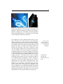
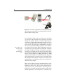
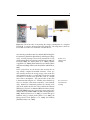
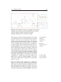
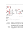
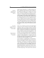
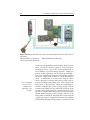
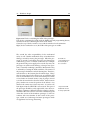
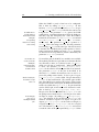
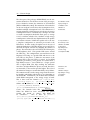
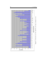
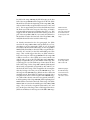
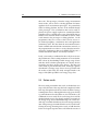
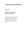
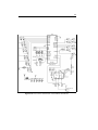
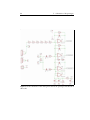
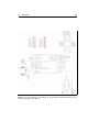
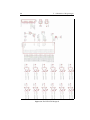
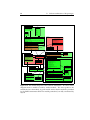
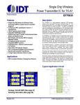
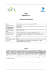
3.1
Hardware design
23
Figure 3.7: The breakdown of the LED PCB.
(1) Twelve LEDs of the LED PCB.
(2) Connection to the MCU and the power supply.
(3) Power supply of the LED driver.
(4) Resistors to configure the constant current of the LED
driver.
of the LED driver to the MCU and the connection to the
power supply. How the LED driver is coupled to the connections to the power supply is denoted by 3 in figure 3.7.
A capacitor is used to stabilize the power supply to the LED
driver. In figure 3.7, number 4 shows how the current of the
LED driver is configured. There are several options possible for the constant current value possible, therefore a configuration is needed. The configuration consists of putting
a certain amount of resistance on the IREF port of the LED
driver. The exact resistance value for a constant current can
be looked up in the datasheet from the LED driver, available in Appendix C.1. This concludes the broad overview
of the design of the circuits of the prototype introduced in
this work.
We have seen that the basis for this design are the EM773
smartmeter (MCU and measurement) and PowerSocket
[Heller and Borchers, 2011] (animation, requirements for
LED PCB). I will now continue with the first version of the
prototype I constructed.
the constant current
of the LED driver is
configured using
resistors