1
User’s/Programmer’s Reference
Volume 1
Core Spectrum Analyzer Functions
ESA Series Spectrum Analyzers
Refer to Volume 2 for one-button power measurements information.
This manual provides documentation for the following instruments:
Agilent Technologies ESA-E Series
E4401B (9 kHz- 1.5 GHz)
E4402B (9 kHz - 3.0 GHz)
E4404B (9 kHz - 6.7 GHz)
E4405B (9 kHz - 13.2 GHz)
E4407B (9 kHz - 26.5 GHz)
Agilent Technologies ESA-L Series
E4411B (9 kHz- 1.5 GHz)
E4403B (9 kHz - 3.0 GHz)
E4408B (9 kHz - 26.5 GHz)
Manufacturing Part Number: E4401-90507
Supersedes: December 2006
Printed in USA
February 2010
© Copyright 1999-2010 Agilent Technologies
Notice
The information contained in this document is subject to change without notice.
Agilent Technologies makes no warranty of any kind with regard to this material,
including but not limited to, the implied warranties of merchantability and fitness
for a particular purpose. Agilent Technologies shall not be liable for errors
contained herein or for incidental or consequential damages in connection with the
furnishing, performance, or use of this material.
Safety Information
The following safety symbols are used throughout this manual. Familiarize
yourself with the symbols and their meaning before operating this instrument.
WARNING
Warning denotes a hazard. It calls attention to a procedure which, if not
correctly performed or adhered to, could result in injury or loss of life. Do not
proceed beyond a warning note until the indicated conditions are fully
understood and met.
CAUTION
Caution denotes a hazard. It calls attention to a procedure that, if not correctly
performed or adhered to, could result in damage to or destruction of the
instrument. Do not proceed beyond a caution sign until the indicated conditions are
fully understood and met.
NOTE
Note calls out special information for the user’s attention. It provides operational
information or additional instructions of which the user should be aware.
The instruction documentation symbol. The product is marked
with this symbol when it is necessary for the user to refer to the
instructions in the documentation.
This symbol is used to mark the on position of the power line
switch.
This symbol is used to mark the standby position of the power
line switch.
This symbol indicates that the input power required is AC.
WARNING
This is a Safety Class 1 Product (provided with a protective earth ground
incorporated in the power cord). The mains plug shall be inserted only in a
socket outlet provided with a protected earth contact. Any interruption of the
2
protective conductor inside or outside of the product is likely to make the
product dangerous. Intentional interruption is prohibited.
WARNING
No operator serviceable parts inside. Refer servicing to qualified personnel.
To prevent electrical shock do not remove covers.
WARNING
If this product is not used as specified, the protection provided by the
equipment could be impaired. This product must be used in a normal
condition (in which all means for protection are intact) only.
CAUTION
Always use the three-prong AC power cord supplied with this product. Failure to
ensure adequate grounding may cause product damage.
Where to Find the Latest Information
Documentation is updated periodically. For the latest information about Agilent
Technologies ESA Spectrum Analyzers, including firmware upgrades and
application information, please visit the following Internet URL:
http://www.agilent.com/find/esa
Microsoft® is a U.S. registered trademark of Microsoft Corp.
Bluetooth™ is a trademark owned by its proprietor and used under license.
NOTE
If the ESA Spectrum Analyzer experiences a rapid “power down / power up”
sequence, the analyzer may not have fully powered down. If this occurs, Agilent
recommends that you power down the analyzer (using the front-panel power
switch) for approximately 10 seconds, then turn the power back on. This will allow
the hardware to turn on in the correct state.
3
4
Contents
Table of Contents
1. Using This Document
What is in This Book . . . . . . . . . . . . . . . . . . . . . . . . . . . . . . . . . . . . . . . . . . . . . . . . . . . . . . . . . . . . .36
2. Front-Panel Key Reference
AMPLITUDE Y Scale . . . . . . . . . . . . . . . . . . . . . . . . . . . . . . . . . . . . . . . . . . . . . . . . . . . . . . . . . . . .38
Auto Couple . . . . . . . . . . . . . . . . . . . . . . . . . . . . . . . . . . . . . . . . . . . . . . . . . . . . . . . . . . . . . . . . . . . .52
Bk Sp (Backspace) . . . . . . . . . . . . . . . . . . . . . . . . . . . . . . . . . . . . . . . . . . . . . . . . . . . . . . . . . . . . . . .59
BW/Avg . . . . . . . . . . . . . . . . . . . . . . . . . . . . . . . . . . . . . . . . . . . . . . . . . . . . . . . . . . . . . . . . . . . . . . .60
Det/Demod . . . . . . . . . . . . . . . . . . . . . . . . . . . . . . . . . . . . . . . . . . . . . . . . . . . . . . . . . . . . . . . . . . . . .64
Display . . . . . . . . . . . . . . . . . . . . . . . . . . . . . . . . . . . . . . . . . . . . . . . . . . . . . . . . . . . . . . . . . . . . . . . .71
Enter . . . . . . . . . . . . . . . . . . . . . . . . . . . . . . . . . . . . . . . . . . . . . . . . . . . . . . . . . . . . . . . . . . . . . . . . . .79
ESC . . . . . . . . . . . . . . . . . . . . . . . . . . . . . . . . . . . . . . . . . . . . . . . . . . . . . . . . . . . . . . . . . . . . . . . . . . .80
File . . . . . . . . . . . . . . . . . . . . . . . . . . . . . . . . . . . . . . . . . . . . . . . . . . . . . . . . . . . . . . . . . . . . . . . . . . .81
Freq Count . . . . . . . . . . . . . . . . . . . . . . . . . . . . . . . . . . . . . . . . . . . . . . . . . . . . . . . . . . . . . . . . . . . . .95
FREQUENCY Channel . . . . . . . . . . . . . . . . . . . . . . . . . . . . . . . . . . . . . . . . . . . . . . . . . . . . . . . . . . .96
Help. . . . . . . . . . . . . . . . . . . . . . . . . . . . . . . . . . . . . . . . . . . . . . . . . . . . . . . . . . . . . . . . . . . . . . . . . . .99
Input/Output . . . . . . . . . . . . . . . . . . . . . . . . . . . . . . . . . . . . . . . . . . . . . . . . . . . . . . . . . . . . . . . . . . .100
Marker. . . . . . . . . . . . . . . . . . . . . . . . . . . . . . . . . . . . . . . . . . . . . . . . . . . . . . . . . . . . . . . . . . . . . . . .105
Marker → . . . . . . . . . . . . . . . . . . . . . . . . . . . . . . . . . . . . . . . . . . . . . . . . . . . . . . . . . . . . . . . . . . . . . 110
MEASURE (Spectrum Analysis Mode) . . . . . . . . . . . . . . . . . . . . . . . . . . . . . . . . . . . . . . . . . . . . . 111
Meas Control. . . . . . . . . . . . . . . . . . . . . . . . . . . . . . . . . . . . . . . . . . . . . . . . . . . . . . . . . . . . . . . . . . . 112
MODE. . . . . . . . . . . . . . . . . . . . . . . . . . . . . . . . . . . . . . . . . . . . . . . . . . . . . . . . . . . . . . . . . . . . . . . . 113
Next Window . . . . . . . . . . . . . . . . . . . . . . . . . . . . . . . . . . . . . . . . . . . . . . . . . . . . . . . . . . . . . . . . . . 114
Peak Search. . . . . . . . . . . . . . . . . . . . . . . . . . . . . . . . . . . . . . . . . . . . . . . . . . . . . . . . . . . . . . . . . . . . 115
Preset. . . . . . . . . . . . . . . . . . . . . . . . . . . . . . . . . . . . . . . . . . . . . . . . . . . . . . . . . . . . . . . . . . . . . . . . .120
Print. . . . . . . . . . . . . . . . . . . . . . . . . . . . . . . . . . . . . . . . . . . . . . . . . . . . . . . . . . . . . . . . . . . . . . . . . .125
Print Setup. . . . . . . . . . . . . . . . . . . . . . . . . . . . . . . . . . . . . . . . . . . . . . . . . . . . . . . . . . . . . . . . . . . . .126
Restart . . . . . . . . . . . . . . . . . . . . . . . . . . . . . . . . . . . . . . . . . . . . . . . . . . . . . . . . . . . . . . . . . . . . . . .128
Return . . . . . . . . . . . . . . . . . . . . . . . . . . . . . . . . . . . . . . . . . . . . . . . . . . . . . . . . . . . . . . . . . . . . . . . .129
Save. . . . . . . . . . . . . . . . . . . . . . . . . . . . . . . . . . . . . . . . . . . . . . . . . . . . . . . . . . . . . . . . . . . . . . . . . .130
Single . . . . . . . . . . . . . . . . . . . . . . . . . . . . . . . . . . . . . . . . . . . . . . . . . . . . . . . . . . . . . . . . . . . . . . . .131
Source . . . . . . . . . . . . . . . . . . . . . . . . . . . . . . . . . . . . . . . . . . . . . . . . . . . . . . . . . . . . . . . . . . . . . . . .132
SPAN X Scale . . . . . . . . . . . . . . . . . . . . . . . . . . . . . . . . . . . . . . . . . . . . . . . . . . . . . . . . . . . . . . . . . .136
Standby . . . . . . . . . . . . . . . . . . . . . . . . . . . . . . . . . . . . . . . . . . . . . . . . . . . . . . . . . . . . . . . . . . . . . . .141
Sweep . . . . . . . . . . . . . . . . . . . . . . . . . . . . . . . . . . . . . . . . . . . . . . . . . . . . . . . . . . . . . . . . . . . . . . . .142
System (Local) . . . . . . . . . . . . . . . . . . . . . . . . . . . . . . . . . . . . . . . . . . . . . . . . . . . . . . . . . . . . . . . . .151
Tab Keys . . . . . . . . . . . . . . . . . . . . . . . . . . . . . . . . . . . . . . . . . . . . . . . . . . . . . . . . . . . . . . . . . . . . . .162
Trace/View . . . . . . . . . . . . . . . . . . . . . . . . . . . . . . . . . . . . . . . . . . . . . . . . . . . . . . . . . . . . . . . . . . . .163
Trig . . . . . . . . . . . . . . . . . . . . . . . . . . . . . . . . . . . . . . . . . . . . . . . . . . . . . . . . . . . . . . . . . . . . . . . . . .167
⇑ (UP) and ⇓ (DOWN) Arrow Keys . . . . . . . . . . . . . . . . . . . . . . . . . . . . . . . . . . . . . . . . . . . . . . . .172
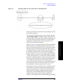
Viewing Angle . . . . . . . . . . . . . . . . . . . . . . . . . . . . . . . . . . . . . . . . . . . . . . . . . . . . . . . . . . . . . . . . .173
Zoom . . . . . . . . . . . . . . . . . . . . . . . . . . . . . . . . . . . . . . . . . . . . . . . . . . . . . . . . . . . . . . . . . . . . . . . . .174
5
Table of Contents
Contents
3. Programming Fundamentals
Creating Valid Commands . . . . . . . . . . . . . . . . . . . . . . . . . . . . . . . . . . . . . . . . . . . . . . . . . . . . . . . . 177
Command Notation Syntax . . . . . . . . . . . . . . . . . . . . . . . . . . . . . . . . . . . . . . . . . . . . . . . . . . . . . . . 178
Special Characters in Commands. . . . . . . . . . . . . . . . . . . . . . . . . . . . . . . . . . . . . . . . . . . . . . . . . . . 179
Parameters in Commands . . . . . . . . . . . . . . . . . . . . . . . . . . . . . . . . . . . . . . . . . . . . . . . . . . . . . . . . . 180
Improving Measurement Speed . . . . . . . . . . . . . . . . . . . . . . . . . . . . . . . . . . . . . . . . . . . . . . . . . . . . 183
Turn off the display updates . . . . . . . . . . . . . . . . . . . . . . . . . . . . . . . . . . . . . . . . . . . . . . . . . . . . . 183
Disable auto alignment . . . . . . . . . . . . . . . . . . . . . . . . . . . . . . . . . . . . . . . . . . . . . . . . . . . . . . . . . 183
Use a fixed IF Gain range . . . . . . . . . . . . . . . . . . . . . . . . . . . . . . . . . . . . . . . . . . . . . . . . . . . . . . . 183
Disable the IF/Video/Sweep output ports . . . . . . . . . . . . . . . . . . . . . . . . . . . . . . . . . . . . . . . . . . . 184
Select phase noise performance . . . . . . . . . . . . . . . . . . . . . . . . . . . . . . . . . . . . . . . . . . . . . . . . . . 184
Use binary data format instead of ASCII . . . . . . . . . . . . . . . . . . . . . . . . . . . . . . . . . . . . . . . . . . . 184
Minimize the number of GPIB transactions. . . . . . . . . . . . . . . . . . . . . . . . . . . . . . . . . . . . . . . . . 184
Avoid unnecessary use of *RST.. . . . . . . . . . . . . . . . . . . . . . . . . . . . . . . . . . . . . . . . . . . . . . . . . . 185
Minimize DUT/instrument setup changes. . . . . . . . . . . . . . . . . . . . . . . . . . . . . . . . . . . . . . . . . . . 185
Using an Option Mode: Minimize the number of GPIB transactions. . . . . . . . . . . . . . . . . . . . . . 185
Putting Multiple Commands on the Same Line . . . . . . . . . . . . . . . . . . . . . . . . . . . . . . . . . . . . . . . . 186
SCPI Termination and Separator Syntax . . . . . . . . . . . . . . . . . . . . . . . . . . . . . . . . . . . . . . . . . . . 186
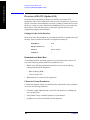
Overview of GPIB (Option A4H) . . . . . . . . . . . . . . . . . . . . . . . . . . . . . . . . . . . . . . . . . . . . . . . . . . 188
GPIB Instrument Nomenclature . . . . . . . . . . . . . . . . . . . . . . . . . . . . . . . . . . . . . . . . . . . . . . . . . . 188
GPIB Command Statements . . . . . . . . . . . . . . . . . . . . . . . . . . . . . . . . . . . . . . . . . . . . . . . . . . . . . 188
Overview of RS-232 (Option 1AX) . . . . . . . . . . . . . . . . . . . . . . . . . . . . . . . . . . . . . . . . . . . . . . . . . 190
Settings for the Serial Interface . . . . . . . . . . . . . . . . . . . . . . . . . . . . . . . . . . . . . . . . . . . . . . . . . . 190
Handshake and Baud Rate . . . . . . . . . . . . . . . . . . . . . . . . . . . . . . . . . . . . . . . . . . . . . . . . . . . . . . 190
Character Format Parameters . . . . . . . . . . . . . . . . . . . . . . . . . . . . . . . . . . . . . . . . . . . . . . . . . . . . 190
Modem Line Handshaking . . . . . . . . . . . . . . . . . . . . . . . . . . . . . . . . . . . . . . . . . . . . . . . . . . . . . . 191
Data Transfer Errors . . . . . . . . . . . . . . . . . . . . . . . . . . . . . . . . . . . . . . . . . . . . . . . . . . . . . . . . . . . 191
4. Status Registers
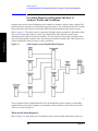
Use Status Registers to Determine the State of Analyzer Events and Conditions . . . . . . . . . . . . . . 194
What are the Status Registers? . . . . . . . . . . . . . . . . . . . . . . . . . . . . . . . . . . . . . . . . . . . . . . . . . . . 194
How Do You Access the Status Registers?. . . . . . . . . . . . . . . . . . . . . . . . . . . . . . . . . . . . . . . . . . 197
Using the Service Request (SRQ) Method . . . . . . . . . . . . . . . . . . . . . . . . . . . . . . . . . . . . . . . . . . 199
Generating a Service Request . . . . . . . . . . . . . . . . . . . . . . . . . . . . . . . . . . . . . . . . . . . . . . . . . . . . 199
Setting and Querying the Status Register . . . . . . . . . . . . . . . . . . . . . . . . . . . . . . . . . . . . . . . . . . . 200
Details of Bits in All Registers . . . . . . . . . . . . . . . . . . . . . . . . . . . . . . . . . . . . . . . . . . . . . . . . . . . 201
Status Byte Register . . . . . . . . . . . . . . . . . . . . . . . . . . . . . . . . . . . . . . . . . . . . . . . . . . . . . . . . . . . 201
Service Request Enable Register . . . . . . . . . . . . . . . . . . . . . . . . . . . . . . . . . . . . . . . . . . . . . . . . . 202
Standard Event Status Register . . . . . . . . . . . . . . . . . . . . . . . . . . . . . . . . . . . . . . . . . . . . . . . . . . . 203
Standard Event Status Event Enable Register. . . . . . . . . . . . . . . . . . . . . . . . . . . . . . . . . . . . . . . . 205
STATus:OPERation Register . . . . . . . . . . . . . . . . . . . . . . . . . . . . . . . . . . . . . . . . . . . . . . . . . . . . 205
STATus:OPERation Condition and Event Enable Registers . . . . . . . . . . . . . . . . . . . . . . . . . . . . 207
6
Contents
Table of Contents
STATus:QUEStionable Registers . . . . . . . . . . . . . . . . . . . . . . . . . . . . . . . . . . . . . . . . . . . . . . . . .208
STATus:QUEStionable:POWer Register. . . . . . . . . . . . . . . . . . . . . . . . . . . . . . . . . . . . . . . . . . . . 211
Questionable Status Event Enable Register . . . . . . . . . . . . . . . . . . . . . . . . . . . . . . . . . . . . . . . . .212
Questionable Status Power Condition and Event Registers . . . . . . . . . . . . . . . . . . . . . . . . . . . . .214
STATus:QUEStionable:FREQuency Register. . . . . . . . . . . . . . . . . . . . . . . . . . . . . . . . . . . . . . . .215
Questionable Status Frequency Condition and Event Enable Registers . . . . . . . . . . . . . . . . . . . .217
STATus:QUEStionable:CALibration Register . . . . . . . . . . . . . . . . . . . . . . . . . . . . . . . . . . . . . . .218
STATus:QUEStionable:INTegrity:UNCalibrated Register . . . . . . . . . . . . . . . . . . . . . . . . . . . . . .221
Questionable Status Calibration Condition and Event Enable Registers . . . . . . . . . . . . . . . . . . .222
Questionable Status Integrity Uncalibrated Condition and Event Enable Registers. . . . . . . . . . .223
STATus:QUEStionable:INTegrity Register. . . . . . . . . . . . . . . . . . . . . . . . . . . . . . . . . . . . . . . . . .224
Questionable Status Integrity Event Condition and Enable Registers . . . . . . . . . . . . . . . . . . . . .226
5. Remote Command Reference
SCPI Sections and Subsections. . . . . . . . . . . . . . . . . . . . . . . . . . . . . . . . . . . . . . . . . . . . . . . . . . . . .229
IEEE Common Commands. . . . . . . . . . . . . . . . . . . . . . . . . . . . . . . . . . . . . . . . . . . . . . . . . . . . . . . .231
Calibration Query . . . . . . . . . . . . . . . . . . . . . . . . . . . . . . . . . . . . . . . . . . . . . . . . . . . . . . . . . . . . .231
Clear Status . . . . . . . . . . . . . . . . . . . . . . . . . . . . . . . . . . . . . . . . . . . . . . . . . . . . . . . . . . . . . . . . . .231
Standard Event Status Enable . . . . . . . . . . . . . . . . . . . . . . . . . . . . . . . . . . . . . . . . . . . . . . . . . . . .231
Standard Event Status Register Query . . . . . . . . . . . . . . . . . . . . . . . . . . . . . . . . . . . . . . . . . . . . .232
Identification Query . . . . . . . . . . . . . . . . . . . . . . . . . . . . . . . . . . . . . . . . . . . . . . . . . . . . . . . . . . .232
Instrument State Query . . . . . . . . . . . . . . . . . . . . . . . . . . . . . . . . . . . . . . . . . . . . . . . . . . . . . . . . .232
Operation Complete . . . . . . . . . . . . . . . . . . . . . . . . . . . . . . . . . . . . . . . . . . . . . . . . . . . . . . . . . . .233
Query Instrument Options . . . . . . . . . . . . . . . . . . . . . . . . . . . . . . . . . . . . . . . . . . . . . . . . . . . . . .233
Recall. . . . . . . . . . . . . . . . . . . . . . . . . . . . . . . . . . . . . . . . . . . . . . . . . . . . . . . . . . . . . . . . . . . . . . .233
Reset . . . . . . . . . . . . . . . . . . . . . . . . . . . . . . . . . . . . . . . . . . . . . . . . . . . . . . . . . . . . . . . . . . . . . . .234
Save . . . . . . . . . . . . . . . . . . . . . . . . . . . . . . . . . . . . . . . . . . . . . . . . . . . . . . . . . . . . . . . . . . . . . . . .234
Service Request Enable. . . . . . . . . . . . . . . . . . . . . . . . . . . . . . . . . . . . . . . . . . . . . . . . . . . . . . . . .235
Read Status Byte Query . . . . . . . . . . . . . . . . . . . . . . . . . . . . . . . . . . . . . . . . . . . . . . . . . . . . . . . .235
Trigger . . . . . . . . . . . . . . . . . . . . . . . . . . . . . . . . . . . . . . . . . . . . . . . . . . . . . . . . . . . . . . . . . . . . . .235
Self Test Query . . . . . . . . . . . . . . . . . . . . . . . . . . . . . . . . . . . . . . . . . . . . . . . . . . . . . . . . . . . . . . .235
Wait-to-Continue . . . . . . . . . . . . . . . . . . . . . . . . . . . . . . . . . . . . . . . . . . . . . . . . . . . . . . . . . . . . . .235
ABORt Subsystem . . . . . . . . . . . . . . . . . . . . . . . . . . . . . . . . . . . . . . . . . . . . . . . . . . . . . . . . . . . . . .236
Abort . . . . . . . . . . . . . . . . . . . . . . . . . . . . . . . . . . . . . . . . . . . . . . . . . . . . . . . . . . . . . . . . . . . . . . .236
CALCulate Subsystem . . . . . . . . . . . . . . . . . . . . . . . . . . . . . . . . . . . . . . . . . . . . . . . . . . . . . . . . . . .237
NdBpoints . . . . . . . . . . . . . . . . . . . . . . . . . . . . . . . . . . . . . . . . . . . . . . . . . . . . . . . . . . . . . . . . . . .237
NdBresults . . . . . . . . . . . . . . . . . . . . . . . . . . . . . . . . . . . . . . . . . . . . . . . . . . . . . . . . . . . . . . . . . .237
NdBstate . . . . . . . . . . . . . . . . . . . . . . . . . . . . . . . . . . . . . . . . . . . . . . . . . . . . . . . . . . . . . . . . . . . .238
Test Current Trace Data Against all Limit Lines . . . . . . . . . . . . . . . . . . . . . . . . . . . . . . . . . . . . .238
CALCulate:LLINe Subsection . . . . . . . . . . . . . . . . . . . . . . . . . . . . . . . . . . . . . . . . . . . . . . . . . . . . .239
Delete All Limit Lines in Memory . . . . . . . . . . . . . . . . . . . . . . . . . . . . . . . . . . . . . . . . . . . . . . . .239
Control Limit Line Amplitude Interpolation. . . . . . . . . . . . . . . . . . . . . . . . . . . . . . . . . . . . . . . . .239
7
Table of Contents
Contents
Set Fixed or Relative Limit Lines. . . . . . . . . . . . . . . . . . . . . . . . . . . . . . . . . . . . . . . . . . . . . . . . . 239
Set Limit Line X-axis Units . . . . . . . . . . . . . . . . . . . . . . . . . . . . . . . . . . . . . . . . . . . . . . . . . . . . . 240
Control Limit Line Frequency Interpolation . . . . . . . . . . . . . . . . . . . . . . . . . . . . . . . . . . . . . . . . 241
Define Limit Line Values . . . . . . . . . . . . . . . . . . . . . . . . . . . . . . . . . . . . . . . . . . . . . . . . . . . . . . . 241
Merge Additional Values into the Existing Limit Line . . . . . . . . . . . . . . . . . . . . . . . . . . . . . . . . 243
Delete Limit Line . . . . . . . . . . . . . . . . . . . . . . . . . . . . . . . . . . . . . . . . . . . . . . . . . . . . . . . . . . . . . 243
Display the Limit Line . . . . . . . . . . . . . . . . . . . . . . . . . . . . . . . . . . . . . . . . . . . . . . . . . . . . . . . . . 244
Test the Data Against the Limit Line . . . . . . . . . . . . . . . . . . . . . . . . . . . . . . . . . . . . . . . . . . . . . . 244
Set the Margin Size. . . . . . . . . . . . . . . . . . . . . . . . . . . . . . . . . . . . . . . . . . . . . . . . . . . . . . . . . . . . 244
Display the Limit Margin . . . . . . . . . . . . . . . . . . . . . . . . . . . . . . . . . . . . . . . . . . . . . . . . . . . . . . . 244
Control Limit Line Testing . . . . . . . . . . . . . . . . . . . . . . . . . . . . . . . . . . . . . . . . . . . . . . . . . . . . . . 245
Select the Type of Limit Line . . . . . . . . . . . . . . . . . . . . . . . . . . . . . . . . . . . . . . . . . . . . . . . . . . . 245
CALCulate:MARKer Subsection. . . . . . . . . . . . . . . . . . . . . . . . . . . . . . . . . . . . . . . . . . . . . . . . . . . 246
Markers All Off on All Traces . . . . . . . . . . . . . . . . . . . . . . . . . . . . . . . . . . . . . . . . . . . . . . . . . . . 246
Continuous Peaking Marker Function . . . . . . . . . . . . . . . . . . . . . . . . . . . . . . . . . . . . . . . . . . . . . 246
Frequency Counter Marker Resolution. . . . . . . . . . . . . . . . . . . . . . . . . . . . . . . . . . . . . . . . . . . . . 246
Frequency Counter Marker Automatic Resolution . . . . . . . . . . . . . . . . . . . . . . . . . . . . . . . . . . . 247
Frequency Counter Marker . . . . . . . . . . . . . . . . . . . . . . . . . . . . . . . . . . . . . . . . . . . . . . . . . . . . . 247
Frequency Counter Marker Query . . . . . . . . . . . . . . . . . . . . . . . . . . . . . . . . . . . . . . . . . . . . . . . . 247
Marker Function . . . . . . . . . . . . . . . . . . . . . . . . . . . . . . . . . . . . . . . . . . . . . . . . . . . . . . . . . . . . . 248
Marker Peak (Maximum) Search . . . . . . . . . . . . . . . . . . . . . . . . . . . . . . . . . . . . . . . . . . . . . . . . . 248
Marker Peak (Maximum) Left Search . . . . . . . . . . . . . . . . . . . . . . . . . . . . . . . . . . . . . . . . . . . . . 248
Marker Next Peak (Maximum) Search . . . . . . . . . . . . . . . . . . . . . . . . . . . . . . . . . . . . . . . . . . . . . 249
Marker Peak (Maximum) Right Search . . . . . . . . . . . . . . . . . . . . . . . . . . . . . . . . . . . . . . . . . . . . 249
Marker Peak (Minimum) Search . . . . . . . . . . . . . . . . . . . . . . . . . . . . . . . . . . . . . . . . . . . . . . . . . 249
Marker Mode . . . . . . . . . . . . . . . . . . . . . . . . . . . . . . . . . . . . . . . . . . . . . . . . . . . . . . . . . . . . . . . . 249
Define Peak Excursion . . . . . . . . . . . . . . . . . . . . . . . . . . . . . . . . . . . . . . . . . . . . . . . . . . . . . . . . . 250
Define Peak Search . . . . . . . . . . . . . . . . . . . . . . . . . . . . . . . . . . . . . . . . . . . . . . . . . . . . . . . . . . . . 251
Define Peak Threshold . . . . . . . . . . . . . . . . . . . . . . . . . . . . . . . . . . . . . . . . . . . . . . . . . . . . . . . . . 251
Peak to Peak Delta Markers . . . . . . . . . . . . . . . . . . . . . . . . . . . . . . . . . . . . . . . . . . . . . . . . . . . . . 251
Set Center Frequency to the Marker Value . . . . . . . . . . . . . . . . . . . . . . . . . . . . . . . . . . . . . . . . . . 252
Set Reference Level to the Marker Value . . . . . . . . . . . . . . . . . . . . . . . . . . . . . . . . . . . . . . . . . . . 252
Set Span to the Marker Value . . . . . . . . . . . . . . . . . . . . . . . . . . . . . . . . . . . . . . . . . . . . . . . . . . . . 252
Set Start Frequency to the Marker Value . . . . . . . . . . . . . . . . . . . . . . . . . . . . . . . . . . . . . . . . . . . 252
Set Center Frequency Step Size to the Marker Value . . . . . . . . . . . . . . . . . . . . . . . . . . . . . . . . . . 253
Set Stop Frequency to the Marker Value . . . . . . . . . . . . . . . . . . . . . . . . . . . . . . . . . . . . . . . . . . . 253
Marker On/Off . . . . . . . . . . . . . . . . . . . . . . . . . . . . . . . . . . . . . . . . . . . . . . . . . . . . . . . . . . . . . . . 253
Marker Table On/Off . . . . . . . . . . . . . . . . . . . . . . . . . . . . . . . . . . . . . . . . . . . . . . . . . . . . . . . . . . 253
Marker to Trace. . . . . . . . . . . . . . . . . . . . . . . . . . . . . . . . . . . . . . . . . . . . . . . . . . . . . . . . . . . . . . . 254
Marker to Trace Auto . . . . . . . . . . . . . . . . . . . . . . . . . . . . . . . . . . . . . . . . . . . . . . . . . . . . . . . . . . 254
Continuous Signal Tracking Function . . . . . . . . . . . . . . . . . . . . . . . . . . . . . . . . . . . . . . . . . . . . . 254
Marker X Value . . . . . . . . . . . . . . . . . . . . . . . . . . . . . . . . . . . . . . . . . . . . . . . . . . . . . . . . . . . . . . 255
8
Contents
Table of Contents
Span Markers Center Frequency X Value . . . . . . . . . . . . . . . . . . . . . . . . . . . . . . . . . . . . . . . . . .255
Marker X Position . . . . . . . . . . . . . . . . . . . . . . . . . . . . . . . . . . . . . . . . . . . . . . . . . . . . . . . . . . . .255
Span Markers Center Frequency X Position . . . . . . . . . . . . . . . . . . . . . . . . . . . . . . . . . . . . . . . .256
Span Markers Span X Position . . . . . . . . . . . . . . . . . . . . . . . . . . . . . . . . . . . . . . . . . . . . . . . . . . .256
Delta Pair Markers Start Frequency X Position . . . . . . . . . . . . . . . . . . . . . . . . . . . . . . . . . . . . . .256
Delta Pair Markers Stop Frequency X Position . . . . . . . . . . . . . . . . . . . . . . . . . . . . . . . . . . . . . .257
Marker X-Axis Readout . . . . . . . . . . . . . . . . . . . . . . . . . . . . . . . . . . . . . . . . . . . . . . . . . . . . . . . .257
Span Markers Span X Value . . . . . . . . . . . . . . . . . . . . . . . . . . . . . . . . . . . . . . . . . . . . . . . . . . . . .258
Delta Pair Markers Start Frequency X Value . . . . . . . . . . . . . . . . . . . . . . . . . . . . . . . . . . . . . . . .258
Delta Pair Markers Stop Frequency X Value . . . . . . . . . . . . . . . . . . . . . . . . . . . . . . . . . . . . . . . .258
Marker Read Y Value . . . . . . . . . . . . . . . . . . . . . . . . . . . . . . . . . . . . . . . . . . . . . . . . . . . . . . . . . .259
CALCulate:NTData Subsection . . . . . . . . . . . . . . . . . . . . . . . . . . . . . . . . . . . . . . . . . . . . . . . . . . . .260
Normalize the Trace Data . . . . . . . . . . . . . . . . . . . . . . . . . . . . . . . . . . . . . . . . . . . . . . . . . . . . . . .260
CALibration Subsystem . . . . . . . . . . . . . . . . . . . . . . . . . . . . . . . . . . . . . . . . . . . . . . . . . . . . . . . . . .261
Align All Instrument Assemblies . . . . . . . . . . . . . . . . . . . . . . . . . . . . . . . . . . . . . . . . . . . . . . . . .261
Set Auto Align Mode All or Not RF . . . . . . . . . . . . . . . . . . . . . . . . . . . . . . . . . . . . . . . . . . . . . . .261
Automatic Alignment . . . . . . . . . . . . . . . . . . . . . . . . . . . . . . . . . . . . . . . . . . . . . . . . . . . . . . . . . .262
Return to the Default Alignment Data . . . . . . . . . . . . . . . . . . . . . . . . . . . . . . . . . . . . . . . . . . . . .262
Align FM Demodulation . . . . . . . . . . . . . . . . . . . . . . . . . . . . . . . . . . . . . . . . . . . . . . . . . . . . . . . .262
Query the Internal or External Frequency Reference . . . . . . . . . . . . . . . . . . . . . . . . . . . . . . . . . .263
Coarse Adjust the Frequency Reference . . . . . . . . . . . . . . . . . . . . . . . . . . . . . . . . . . . . . . . . . . . .263
Fine Adjust the Frequency Reference . . . . . . . . . . . . . . . . . . . . . . . . . . . . . . . . . . . . . . . . . . . . . .263
Select the Frequency Corrections . . . . . . . . . . . . . . . . . . . . . . . . . . . . . . . . . . . . . . . . . . . . . . . . .263
Align the RF Circuitry . . . . . . . . . . . . . . . . . . . . . . . . . . . . . . . . . . . . . . . . . . . . . . . . . . . . . . . . .264
Select the Source State for Calibration . . . . . . . . . . . . . . . . . . . . . . . . . . . . . . . . . . . . . . . . . . . . .264
Calibrate the Tracking Generator . . . . . . . . . . . . . . . . . . . . . . . . . . . . . . . . . . . . . . . . . . . . . . . . .265
CONFigure Subsystem . . . . . . . . . . . . . . . . . . . . . . . . . . . . . . . . . . . . . . . . . . . . . . . . . . . . . . . . . . .266
Configure the Basic Spectrum Analyzer State . . . . . . . . . . . . . . . . . . . . . . . . . . . . . . . . . . . . . . .266
COUPle Subsystem. . . . . . . . . . . . . . . . . . . . . . . . . . . . . . . . . . . . . . . . . . . . . . . . . . . . . . . . . . . . . .267
COUPle the Function to Other Settings . . . . . . . . . . . . . . . . . . . . . . . . . . . . . . . . . . . . . . . . . . . .267
DISPlay Subsystem. . . . . . . . . . . . . . . . . . . . . . . . . . . . . . . . . . . . . . . . . . . . . . . . . . . . . . . . . . . . . .269
Active Function Position . . . . . . . . . . . . . . . . . . . . . . . . . . . . . . . . . . . . . . . . . . . . . . . . . . . . . . .269
Display Viewing Angle . . . . . . . . . . . . . . . . . . . . . . . . . . . . . . . . . . . . . . . . . . . . . . . . . . . . . . . .269
Date and Time Display Format . . . . . . . . . . . . . . . . . . . . . . . . . . . . . . . . . . . . . . . . . . . . . . . . . . .269
Date and Time Display . . . . . . . . . . . . . . . . . . . . . . . . . . . . . . . . . . . . . . . . . . . . . . . . . . . . . . . . .270
Display Annotation Title Data . . . . . . . . . . . . . . . . . . . . . . . . . . . . . . . . . . . . . . . . . . . . . . . . . . .270
Turn the Entire Display On/Off . . . . . . . . . . . . . . . . . . . . . . . . . . . . . . . . . . . . . . . . . . . . . . . . . .270
Turn the Full Screen Display On/Off . . . . . . . . . . . . . . . . . . . . . . . . . . . . . . . . . . . . . . . . . . . . . .271
Window Annotation . . . . . . . . . . . . . . . . . . . . . . . . . . . . . . . . . . . . . . . . . . . . . . . . . . . . . . . . . . .271
Trace Graticule Display. . . . . . . . . . . . . . . . . . . . . . . . . . . . . . . . . . . . . . . . . . . . . . . . . . . . . . . . .271
Trace X-Axis Scale Offset . . . . . . . . . . . . . . . . . . . . . . . . . . . . . . . . . . . . . . . . . . . . . . . . . . . . . .271
Display Line Amplitude . . . . . . . . . . . . . . . . . . . . . . . . . . . . . . . . . . . . . . . . . . . . . . . . . . . . . . . .272
9
Table of Contents
Contents
Display Line On/Off . . . . . . . . . . . . . . . . . . . . . . . . . . . . . . . . . . . . . . . . . . . . . . . . . . . . . . . . . . . 272
IF Gain Auto/Reference Level Auto Ranging . . . . . . . . . . . . . . . . . . . . . . . . . . . . . . . . . . . . . . . 273
Normalized Reference Level . . . . . . . . . . . . . . . . . . . . . . . . . . . . . . . . . . . . . . . . . . . . . . . . . . . . 273
Normalized Reference Level Position . . . . . . . . . . . . . . . . . . . . . . . . . . . . . . . . . . . . . . . . . . . . . 274
Trace Y-Axis Amplitude Scaling . . . . . . . . . . . . . . . . . . . . . . . . . . . . . . . . . . . . . . . . . . . . . . . . . 274
Trace Y-Axis Frequency Scaling . . . . . . . . . . . . . . . . . . . . . . . . . . . . . . . . . . . . . . . . . . . . . . . . . 274
Trace Y-Axis Reference Level . . . . . . . . . . . . . . . . . . . . . . . . . . . . . . . . . . . . . . . . . . . . . . . . . . . 275
Trace Y-Axis Reference Level Offset . . . . . . . . . . . . . . . . . . . . . . . . . . . . . . . . . . . . . . . . . . . . . . 276
Vertical Axis Scaling . . . . . . . . . . . . . . . . . . . . . . . . . . . . . . . . . . . . . . . . . . . . . . . . . . . . . . . . . . 277
FORMat Subsystem . . . . . . . . . . . . . . . . . . . . . . . . . . . . . . . . . . . . . . . . . . . . . . . . . . . . . . . . . . . . . 278
Byte Order . . . . . . . . . . . . . . . . . . . . . . . . . . . . . . . . . . . . . . . . . . . . . . . . . . . . . . . . . . . . . . . . . . 278
Numeric Data format . . . . . . . . . . . . . . . . . . . . . . . . . . . . . . . . . . . . . . . . . . . . . . . . . . . . . . . . . . 278
HCOPy Subsystem . . . . . . . . . . . . . . . . . . . . . . . . . . . . . . . . . . . . . . . . . . . . . . . . . . . . . . . . . . . . . . 281
Abort the Print . . . . . . . . . . . . . . . . . . . . . . . . . . . . . . . . . . . . . . . . . . . . . . . . . . . . . . . . . . . . . . . 281
Printer Type. . . . . . . . . . . . . . . . . . . . . . . . . . . . . . . . . . . . . . . . . . . . . . . . . . . . . . . . . . . . . . . . . . 281
Color Hard Copy. . . . . . . . . . . . . . . . . . . . . . . . . . . . . . . . . . . . . . . . . . . . . . . . . . . . . . . . . . . . . . 281
Print a Hard Copy . . . . . . . . . . . . . . . . . . . . . . . . . . . . . . . . . . . . . . . . . . . . . . . . . . . . . . . . . . . . 282
Form Feed the Print Item . . . . . . . . . . . . . . . . . . . . . . . . . . . . . . . . . . . . . . . . . . . . . . . . . . . . . . . 282
Page Orientation . . . . . . . . . . . . . . . . . . . . . . . . . . . . . . . . . . . . . . . . . . . . . . . . . . . . . . . . . . . . . . 282
Number of Items Printed on a Page . . . . . . . . . . . . . . . . . . . . . . . . . . . . . . . . . . . . . . . . . . . . . . . 282
Printed Page Size . . . . . . . . . . . . . . . . . . . . . . . . . . . . . . . . . . . . . . . . . . . . . . . . . . . . . . . . . . . . . 283
INITiate Subsystem . . . . . . . . . . . . . . . . . . . . . . . . . . . . . . . . . . . . . . . . . . . . . . . . . . . . . . . . . . . . . 284
Continuous or Single Measurements . . . . . . . . . . . . . . . . . . . . . . . . . . . . . . . . . . . . . . . . . . . . . . 284
Take New Data Acquisitions . . . . . . . . . . . . . . . . . . . . . . . . . . . . . . . . . . . . . . . . . . . . . . . . . . . . 285
Pause the Measurement . . . . . . . . . . . . . . . . . . . . . . . . . . . . . . . . . . . . . . . . . . . . . . . . . . . . . . . . 285
Restart the Measurement . . . . . . . . . . . . . . . . . . . . . . . . . . . . . . . . . . . . . . . . . . . . . . . . . . . . . . . 286
Resume the Measurement . . . . . . . . . . . . . . . . . . . . . . . . . . . . . . . . . . . . . . . . . . . . . . . . . . . . . . 286
INPut Subsystem . . . . . . . . . . . . . . . . . . . . . . . . . . . . . . . . . . . . . . . . . . . . . . . . . . . . . . . . . . . . . . . 287
Input Port Coupling . . . . . . . . . . . . . . . . . . . . . . . . . . . . . . . . . . . . . . . . . . . . . . . . . . . . . . . . . . . 287
Select Internal or External Mixer . . . . . . . . . . . . . . . . . . . . . . . . . . . . . . . . . . . . . . . . . . . . . . . . . 288
Select Mixer Type . . . . . . . . . . . . . . . . . . . . . . . . . . . . . . . . . . . . . . . . . . . . . . . . . . . . . . . . . . . . . 288
Clear the Input Overload . . . . . . . . . . . . . . . . . . . . . . . . . . . . . . . . . . . . . . . . . . . . . . . . . . . . . . . 289
INSTrument Subsystem . . . . . . . . . . . . . . . . . . . . . . . . . . . . . . . . . . . . . . . . . . . . . . . . . . . . . . . . . . 290
Catalog Query . . . . . . . . . . . . . . . . . . . . . . . . . . . . . . . . . . . . . . . . . . . . . . . . . . . . . . . . . . . . . . . 290
Select Application by Number . . . . . . . . . . . . . . . . . . . . . . . . . . . . . . . . . . . . . . . . . . . . . . . . . . . 290
Select Application . . . . . . . . . . . . . . . . . . . . . . . . . . . . . . . . . . . . . . . . . . . . . . . . . . . . . . . . . . . . 291
MMEMory Subsystem . . . . . . . . . . . . . . . . . . . . . . . . . . . . . . . . . . . . . . . . . . . . . . . . . . . . . . . . . . . 293
Catalog the Selected Memory Location . . . . . . . . . . . . . . . . . . . . . . . . . . . . . . . . . . . . . . . . . . . . 293
Copy a File . . . . . . . . . . . . . . . . . . . . . . . . . . . . . . . . . . . . . . . . . . . . . . . . . . . . . . . . . . . . . . . . . . 293
Move Data to File . . . . . . . . . . . . . . . . . . . . . . . . . . . . . . . . . . . . . . . . . . . . . . . . . . . . . . . . . . . . 294
Delete a File . . . . . . . . . . . . . . . . . . . . . . . . . . . . . . . . . . . . . . . . . . . . . . . . . . . . . . . . . . . . . . . . . 294
Load a Corrections Table from a File . . . . . . . . . . . . . . . . . . . . . . . . . . . . . . . . . . . . . . . . . . . . . . 294
10
Contents
Table of Contents
Load a Limit Line from Memory to the Instrument . . . . . . . . . . . . . . . . . . . . . . . . . . . . . . . . . . .294
Load an Instrument State from a File . . . . . . . . . . . . . . . . . . . . . . . . . . . . . . . . . . . . . . . . . . . . . .295
Load a Trace From a File to the Instrument . . . . . . . . . . . . . . . . . . . . . . . . . . . . . . . . . . . . . . . . .295
Make a Directory . . . . . . . . . . . . . . . . . . . . . . . . . . . . . . . . . . . . . . . . . . . . . . . . . . . . . . . . . . . . .296
Delete a Directory . . . . . . . . . . . . . . . . . . . . . . . . . . . . . . . . . . . . . . . . . . . . . . . . . . . . . . . . . . . . .296
Set the Save Screen Image File Type . . . . . . . . . . . . . . . . . . . . . . . . . . . . . . . . . . . . . . . . . . . . . .296
Set the Save Screen Image Background . . . . . . . . . . . . . . . . . . . . . . . . . . . . . . . . . . . . . . . . . . . .296
Reverse the Colors of the Display. . . . . . . . . . . . . . . . . . . . . . . . . . . . . . . . . . . . . . . . . . . . . . . . .297
Store a Corrections Table to a File . . . . . . . . . . . . . . . . . . . . . . . . . . . . . . . . . . . . . . . . . . . . . . . .297
Store a Limit Line in a File . . . . . . . . . . . . . . . . . . . . . . . . . . . . . . . . . . . . . . . . . . . . . . . . . . . . .297
Store Measurement Results in a File . . . . . . . . . . . . . . . . . . . . . . . . . . . . . . . . . . . . . . . . . . . . . .298
Store a Screen Image in a Graphic File . . . . . . . . . . . . . . . . . . . . . . . . . . . . . . . . . . . . . . . . . . . .298
Store an Instrument State in a File . . . . . . . . . . . . . . . . . . . . . . . . . . . . . . . . . . . . . . . . . . . . . . . .298
Store a Trace in a File . . . . . . . . . . . . . . . . . . . . . . . . . . . . . . . . . . . . . . . . . . . . . . . . . . . . . . . . . .299
OUTPut Subsystem. . . . . . . . . . . . . . . . . . . . . . . . . . . . . . . . . . . . . . . . . . . . . . . . . . . . . . . . . . . . . .300
Turn Output On/Off . . . . . . . . . . . . . . . . . . . . . . . . . . . . . . . . . . . . . . . . . . . . . . . . . . . . . . . . . . .300
SENSe Subsystem. . . . . . . . . . . . . . . . . . . . . . . . . . . . . . . . . . . . . . . . . . . . . . . . . . . . . . . . . . . . . . .301
Auto-range Dwell Time. . . . . . . . . . . . . . . . . . . . . . . . . . . . . . . . . . . . . . . . . . . . . . . . . . . . . . . . .301
[:SENSe]:AVERage Subsection . . . . . . . . . . . . . . . . . . . . . . . . . . . . . . . . . . . . . . . . . . . . . . . . . . . .302
Clear the Current Average. . . . . . . . . . . . . . . . . . . . . . . . . . . . . . . . . . . . . . . . . . . . . . . . . . . . . . .302
Set the Average Count . . . . . . . . . . . . . . . . . . . . . . . . . . . . . . . . . . . . . . . . . . . . . . . . . . . . . . . . .302
Turn Averaging On/Off . . . . . . . . . . . . . . . . . . . . . . . . . . . . . . . . . . . . . . . . . . . . . . . . . . . . . . . .302
Turn Automatic Averaging On/Off . . . . . . . . . . . . . . . . . . . . . . . . . . . . . . . . . . . . . . . . . . . . . . .303
Type of Averaging for Measurements . . . . . . . . . . . . . . . . . . . . . . . . . . . . . . . . . . . . . . . . . . . . . .304
[:SENSe]:BANDwidth Subsection . . . . . . . . . . . . . . . . . . . . . . . . . . . . . . . . . . . . . . . . . . . . . . . . . .306
Resolution Bandwidth . . . . . . . . . . . . . . . . . . . . . . . . . . . . . . . . . . . . . . . . . . . . . . . . . . . . . . . . .306
Resolution Bandwidth Automatic . . . . . . . . . . . . . . . . . . . . . . . . . . . . . . . . . . . . . . . . . . . . . . . . .306
Video Bandwidth . . . . . . . . . . . . . . . . . . . . . . . . . . . . . . . . . . . . . . . . . . . . . . . . . . . . . . . . . . . . .306
Video Bandwidth Automatic . . . . . . . . . . . . . . . . . . . . . . . . . . . . . . . . . . . . . . . . . . . . . . . . . . . .307
Video to Resolution Bandwidth Ratio . . . . . . . . . . . . . . . . . . . . . . . . . . . . . . . . . . . . . . . . . . . . .307
Video to Resolution Bandwidth Ratio Mode Select . . . . . . . . . . . . . . . . . . . . . . . . . . . . . . . . . . .307
[:SENSe]:CORRection Subsection. . . . . . . . . . . . . . . . . . . . . . . . . . . . . . . . . . . . . . . . . . . . . . . . . .309
Delete All Corrections. . . . . . . . . . . . . . . . . . . . . . . . . . . . . . . . . . . . . . . . . . . . . . . . . . . . . . . . . .309
Perform Amplitude Correction . . . . . . . . . . . . . . . . . . . . . . . . . . . . . . . . . . . . . . . . . . . . . . . . . . .309
Set Amplitude Correction Data . . . . . . . . . . . . . . . . . . . . . . . . . . . . . . . . . . . . . . . . . . . . . . . . . .309
Merge Additional Values into the Existing Amplitude Correction Data . . . . . . . . . . . . . . . . . . .310
Delete Amplitude Correction . . . . . . . . . . . . . . . . . . . . . . . . . . . . . . . . . . . . . . . . . . . . . . . . . . . . 311
Set Amplitude Correction Frequency Interpolation . . . . . . . . . . . . . . . . . . . . . . . . . . . . . . . . . . . 311
Perform Amplitude Correction . . . . . . . . . . . . . . . . . . . . . . . . . . . . . . . . . . . . . . . . . . . . . . . . . . . 311
Input Impedance Correction . . . . . . . . . . . . . . . . . . . . . . . . . . . . . . . . . . . . . . . . . . . . . . . . . . . . .312
External Amplifier Correction . . . . . . . . . . . . . . . . . . . . . . . . . . . . . . . . . . . . . . . . . . . . . . . . . . .312
[:SENSe]:DEMod Subsection. . . . . . . . . . . . . . . . . . . . . . . . . . . . . . . . . . . . . . . . . . . . . . . . . . . . . .313
11
Table of Contents
Contents
Type of Demodulation . . . . . . . . . . . . . . . . . . . . . . . . . . . . . . . . . . . . . . . . . . . . . . . . . . . . . . . . . 313
FM Deviation . . . . . . . . . . . . . . . . . . . . . . . . . . . . . . . . . . . . . . . . . . . . . . . . . . . . . . . . . . . . . . . . 313
FM Demodulation Squelch . . . . . . . . . . . . . . . . . . . . . . . . . . . . . . . . . . . . . . . . . . . . . . . . . . . . . . 314
Demodulation Control . . . . . . . . . . . . . . . . . . . . . . . . . . . . . . . . . . . . . . . . . . . . . . . . . . . . . . . . . 314
Demod Time . . . . . . . . . . . . . . . . . . . . . . . . . . . . . . . . . . . . . . . . . . . . . . . . . . . . . . . . . . . . . . . . 315
Demod View . . . . . . . . . . . . . . . . . . . . . . . . . . . . . . . . . . . . . . . . . . . . . . . . . . . . . . . . . . . . . . . . . 315
[:SENSe]:DETector Subsection . . . . . . . . . . . . . . . . . . . . . . . . . . . . . . . . . . . . . . . . . . . . . . . . . . . . 316
Automatic Detection Type Selected . . . . . . . . . . . . . . . . . . . . . . . . . . . . . . . . . . . . . . . . . . . . . . . 316
Type of Detection . . . . . . . . . . . . . . . . . . . . . . . . . . . . . . . . . . . . . . . . . . . . . . . . . . . . . . . . . . . . . 316
Type of EMI Detection . . . . . . . . . . . . . . . . . . . . . . . . . . . . . . . . . . . . . . . . . . . . . . . . . . . . . . . . 317
View of EMI Detection. . . . . . . . . . . . . . . . . . . . . . . . . . . . . . . . . . . . . . . . . . . . . . . . . . . . . . . . . 318
Immediate Auto-Range EMI Detector . . . . . . . . . . . . . . . . . . . . . . . . . . . . . . . . . . . . . . . . . . . . . 319
Auto-Range EMI Detector . . . . . . . . . . . . . . . . . . . . . . . . . . . . . . . . . . . . . . . . . . . . . . . . . . . . . . 319
Remove EMI Auto-Range . . . . . . . . . . . . . . . . . . . . . . . . . . . . . . . . . . . . . . . . . . . . . . . . . . . . . . 319
[:SENSe]:FREQuency Subsection . . . . . . . . . . . . . . . . . . . . . . . . . . . . . . . . . . . . . . . . . . . . . . . . . . 321
Center Frequency . . . . . . . . . . . . . . . . . . . . . . . . . . . . . . . . . . . . . . . . . . . . . . . . . . . . . . . . . . . . . 321
Center Frequency Step Size Automatic . . . . . . . . . . . . . . . . . . . . . . . . . . . . . . . . . . . . . . . . . . . . 321
Center Frequency Step Size . . . . . . . . . . . . . . . . . . . . . . . . . . . . . . . . . . . . . . . . . . . . . . . . . . . . . 322
Frequency Span . . . . . . . . . . . . . . . . . . . . . . . . . . . . . . . . . . . . . . . . . . . . . . . . . . . . . . . . . . . . . . 322
Full Frequency Span . . . . . . . . . . . . . . . . . . . . . . . . . . . . . . . . . . . . . . . . . . . . . . . . . . . . . . . . . . 323
Last Frequency Span. . . . . . . . . . . . . . . . . . . . . . . . . . . . . . . . . . . . . . . . . . . . . . . . . . . . . . . . . . . 323
Start Frequency . . . . . . . . . . . . . . . . . . . . . . . . . . . . . . . . . . . . . . . . . . . . . . . . . . . . . . . . . . . . . . 323
Stop Frequency . . . . . . . . . . . . . . . . . . . . . . . . . . . . . . . . . . . . . . . . . . . . . . . . . . . . . . . . . . . . . . 324
Frequency Synthesis Mode . . . . . . . . . . . . . . . . . . . . . . . . . . . . . . . . . . . . . . . . . . . . . . . . . . . . . . 325
Frequency Synthesis State . . . . . . . . . . . . . . . . . . . . . . . . . . . . . . . . . . . . . . . . . . . . . . . . . . . . . . 325
[SENSe]:MIXer Subsection . . . . . . . . . . . . . . . . . . . . . . . . . . . . . . . . . . . . . . . . . . . . . . . . . . . . . . . 326
Select External Mixer Band . . . . . . . . . . . . . . . . . . . . . . . . . . . . . . . . . . . . . . . . . . . . . . . . . . . . . 326
External Mixer Bias Adjust . . . . . . . . . . . . . . . . . . . . . . . . . . . . . . . . . . . . . . . . . . . . . . . . . . . . . 326
Set External Mixer Bias On/Off . . . . . . . . . . . . . . . . . . . . . . . . . . . . . . . . . . . . . . . . . . . . . . . . . . 327
Set External Mixer LO Harmonic Value . . . . . . . . . . . . . . . . . . . . . . . . . . . . . . . . . . . . . . . . . . . 327
Set External Mixer LO Harmonic Mode . . . . . . . . . . . . . . . . . . . . . . . . . . . . . . . . . . . . . . . . . . . 328
[:SENSe]:POWer Subsection . . . . . . . . . . . . . . . . . . . . . . . . . . . . . . . . . . . . . . . . . . . . . . . . . . . . . . 329
Quasi-peak Detector Gain. . . . . . . . . . . . . . . . . . . . . . . . . . . . . . . . . . . . . . . . . . . . . . . . . . . . . . . 329
Input Attenuation . . . . . . . . . . . . . . . . . . . . . . . . . . . . . . . . . . . . . . . . . . . . . . . . . . . . . . . . . . . . . 329
Input Port Attenuator Auto . . . . . . . . . . . . . . . . . . . . . . . . . . . . . . . . . . . . . . . . . . . . . . . . . . . . . 329
Input Port Power Gain . . . . . . . . . . . . . . . . . . . . . . . . . . . . . . . . . . . . . . . . . . . . . . . . . . . . . . . . . 330
Input Port Maximum Mixer Power. . . . . . . . . . . . . . . . . . . . . . . . . . . . . . . . . . . . . . . . . . . . . . . . 330
Optimize Preselector Frequency . . . . . . . . . . . . . . . . . . . . . . . . . . . . . . . . . . . . . . . . . . . . . . . . . . 330
Preselector Center . . . . . . . . . . . . . . . . . . . . . . . . . . . . . . . . . . . . . . . . . . . . . . . . . . . . . . . . . . . . . 331
[:SENSe]:SIDentify Subsection . . . . . . . . . . . . . . . . . . . . . . . . . . . . . . . . . . . . . . . . . . . . . . . . . . . . 332
Set Mixer Signal Identification Mode . . . . . . . . . . . . . . . . . . . . . . . . . . . . . . . . . . . . . . . . . . . . . 332
Set Mixer Signal Identification State . . . . . . . . . . . . . . . . . . . . . . . . . . . . . . . . . . . . . . . . . . . . . . 332
12
Contents
Table of Contents
[:SENSe]:SWEep Subsection . . . . . . . . . . . . . . . . . . . . . . . . . . . . . . . . . . . . . . . . . . . . . . . . . . . . . .334
Sweep Points . . . . . . . . . . . . . . . . . . . . . . . . . . . . . . . . . . . . . . . . . . . . . . . . . . . . . . . . . . . . . . . . .334
Query Number of Segments . . . . . . . . . . . . . . . . . . . . . . . . . . . . . . . . . . . . . . . . . . . . . . . . . . . . .335
Set All Segment Data . . . . . . . . . . . . . . . . . . . . . . . . . . . . . . . . . . . . . . . . . . . . . . . . . . . . . . . . . .335
Merge Data With Segmented Sweep Data . . . . . . . . . . . . . . . . . . . . . . . . . . . . . . . . . . . . . . . . . .336
Delete All Segmented Sweep Data . . . . . . . . . . . . . . . . . . . . . . . . . . . . . . . . . . . . . . . . . . . . . . .337
Delete Some Segmented Sweep Data . . . . . . . . . . . . . . . . . . . . . . . . . . . . . . . . . . . . . . . . . . . . .337
Turn On/Off Segmented Sweep . . . . . . . . . . . . . . . . . . . . . . . . . . . . . . . . . . . . . . . . . . . . . . . . . .337
Set Frequency Domain Scale Type . . . . . . . . . . . . . . . . . . . . . . . . . . . . . . . . . . . . . . . . . . . . . . .338
Sweep Time . . . . . . . . . . . . . . . . . . . . . . . . . . . . . . . . . . . . . . . . . . . . . . . . . . . . . . . . . . . . . . . . .339
Automatic Sweep Time . . . . . . . . . . . . . . . . . . . . . . . . . . . . . . . . . . . . . . . . . . . . . . . . . . . . . . . .339
Sweep Time Mode . . . . . . . . . . . . . . . . . . . . . . . . . . . . . . . . . . . . . . . . . . . . . . . . . . . . . . . . . . . .340
Time Gating Delay (Option 1D6 Only) . . . . . . . . . . . . . . . . . . . . . . . . . . . . . . . . . . . . . . . . . . . .340
Time Gate Length (Option 1D6 Only) . . . . . . . . . . . . . . . . . . . . . . . . . . . . . . . . . . . . . . . . . . . . .340
Time Gate Level (Option 1D6 Only) . . . . . . . . . . . . . . . . . . . . . . . . . . . . . . . . . . . . . . . . . . . . . .341
Time Gate Polarity (Option 1D6 Only). . . . . . . . . . . . . . . . . . . . . . . . . . . . . . . . . . . . . . . . . . . . .341
Preset Time Gate (Option 1D6 Only) . . . . . . . . . . . . . . . . . . . . . . . . . . . . . . . . . . . . . . . . . . . . . .341
Control Time Gate (Option 1D6 Only) . . . . . . . . . . . . . . . . . . . . . . . . . . . . . . . . . . . . . . . . . . . .342
Time Gate Trigger Type (Option 1D6 Only). . . . . . . . . . . . . . . . . . . . . . . . . . . . . . . . . . . . . . . . .342
SOURce Subsystem . . . . . . . . . . . . . . . . . . . . . . . . . . . . . . . . . . . . . . . . . . . . . . . . . . . . . . . . . . . . .343
Sets the Output Power Offset Correction . . . . . . . . . . . . . . . . . . . . . . . . . . . . . . . . . . . . . . . . . . .343
Source Attenuation . . . . . . . . . . . . . . . . . . . . . . . . . . . . . . . . . . . . . . . . . . . . . . . . . . . . . . . . . . . .343
Automatic Source Attenuation . . . . . . . . . . . . . . . . . . . . . . . . . . . . . . . . . . . . . . . . . . . . . . . . . . .344
Sets the Output Power . . . . . . . . . . . . . . . . . . . . . . . . . . . . . . . . . . . . . . . . . . . . . . . . . . . . . . . . .344
Sets the Source Output Power Mode . . . . . . . . . . . . . . . . . . . . . . . . . . . . . . . . . . . . . . . . . . . . . .345
Set the Source Sweep Power Range . . . . . . . . . . . . . . . . . . . . . . . . . . . . . . . . . . . . . . . . . . . . . . .345
Set the Output Power at the Start of the Sweep . . . . . . . . . . . . . . . . . . . . . . . . . . . . . . . . . . . . . .346
Set the Output Power to Step Automatically . . . . . . . . . . . . . . . . . . . . . . . . . . . . . . . . . . . . . . . .346
Set the Output Power Step Size . . . . . . . . . . . . . . . . . . . . . . . . . . . . . . . . . . . . . . . . . . . . . . . . . .346
Set the Source Sweep Power Range . . . . . . . . . . . . . . . . . . . . . . . . . . . . . . . . . . . . . . . . . . . . . . .347
Output Power Tracking . . . . . . . . . . . . . . . . . . . . . . . . . . . . . . . . . . . . . . . . . . . . . . . . . . . . . . . .347
Output Power Tracking Peak . . . . . . . . . . . . . . . . . . . . . . . . . . . . . . . . . . . . . . . . . . . . . . . . . . . .347
STATus Subsystem . . . . . . . . . . . . . . . . . . . . . . . . . . . . . . . . . . . . . . . . . . . . . . . . . . . . . . . . . . . . . .349
Operation Condition Query . . . . . . . . . . . . . . . . . . . . . . . . . . . . . . . . . . . . . . . . . . . . . . . . . . . . .349
Operation Enable . . . . . . . . . . . . . . . . . . . . . . . . . . . . . . . . . . . . . . . . . . . . . . . . . . . . . . . . . . . . .349
Operation Event Query . . . . . . . . . . . . . . . . . . . . . . . . . . . . . . . . . . . . . . . . . . . . . . . . . . . . . . . . .349
Operation Negative Transition . . . . . . . . . . . . . . . . . . . . . . . . . . . . . . . . . . . . . . . . . . . . . . . . . . .350
Operation Positive Transition . . . . . . . . . . . . . . . . . . . . . . . . . . . . . . . . . . . . . . . . . . . . . . . . . . . .350
Preset the Status Byte . . . . . . . . . . . . . . . . . . . . . . . . . . . . . . . . . . . . . . . . . . . . . . . . . . . . . . . . . .350
STATus:QUEStionable Subsection. . . . . . . . . . . . . . . . . . . . . . . . . . . . . . . . . . . . . . . . . . . . . . . . . .351
Questionable Calibration Condition . . . . . . . . . . . . . . . . . . . . . . . . . . . . . . . . . . . . . . . . . . . . . . .351
Questionable Calibration Enable . . . . . . . . . . . . . . . . . . . . . . . . . . . . . . . . . . . . . . . . . . . . . . . . .351
13
Table of Contents
Contents
Questionable Calibration Event Query . . . . . . . . . . . . . . . . . . . . . . . . . . . . . . . . . . . . . . . . . . . . . 351
Questionable Calibration Negative Transition . . . . . . . . . . . . . . . . . . . . . . . . . . . . . . . . . . . . . . . 352
Questionable Calibration Positive Transition . . . . . . . . . . . . . . . . . . . . . . . . . . . . . . . . . . . . . . . 352
Questionable Condition . . . . . . . . . . . . . . . . . . . . . . . . . . . . . . . . . . . . . . . . . . . . . . . . . . . . . . . . 352
Questionable Enable . . . . . . . . . . . . . . . . . . . . . . . . . . . . . . . . . . . . . . . . . . . . . . . . . . . . . . . . . . 353
Questionable Event Query . . . . . . . . . . . . . . . . . . . . . . . . . . . . . . . . . . . . . . . . . . . . . . . . . . . . . . 353
Questionable Frequency Condition . . . . . . . . . . . . . . . . . . . . . . . . . . . . . . . . . . . . . . . . . . . . . . . 353
Questionable Frequency Enable . . . . . . . . . . . . . . . . . . . . . . . . . . . . . . . . . . . . . . . . . . . . . . . . . 354
Questionable Frequency Event Query . . . . . . . . . . . . . . . . . . . . . . . . . . . . . . . . . . . . . . . . . . . . . 354
Questionable Frequency Negative Transition . . . . . . . . . . . . . . . . . . . . . . . . . . . . . . . . . . . . . . . 354
Questionable Frequency Positive Transition . . . . . . . . . . . . . . . . . . . . . . . . . . . . . . . . . . . . . . . . 355
Questionable Integrity Condition . . . . . . . . . . . . . . . . . . . . . . . . . . . . . . . . . . . . . . . . . . . . . . . . . 355
Questionable Integrity Enable . . . . . . . . . . . . . . . . . . . . . . . . . . . . . . . . . . . . . . . . . . . . . . . . . . . 355
Questionable Integrity Event Query . . . . . . . . . . . . . . . . . . . . . . . . . . . . . . . . . . . . . . . . . . . . . . . 355
Questionable Integrity Negative Transition . . . . . . . . . . . . . . . . . . . . . . . . . . . . . . . . . . . . . . . . . 356
Questionable Integrity Positive Transition . . . . . . . . . . . . . . . . . . . . . . . . . . . . . . . . . . . . . . . . . 356
Questionable Integrity Uncalibrated Enable. . . . . . . . . . . . . . . . . . . . . . . . . . . . . . . . . . . . . . . . . 356
Questionable Integrity Uncalibrated Event Query . . . . . . . . . . . . . . . . . . . . . . . . . . . . . . . . . . . . 357
Questionable Integrity Uncalibrated Negative Transition . . . . . . . . . . . . . . . . . . . . . . . . . . . . . . 357
Questionable Integrity Uncalibrated Positive Transition . . . . . . . . . . . . . . . . . . . . . . . . . . . . . . . 357
Questionable Negative Transition . . . . . . . . . . . . . . . . . . . . . . . . . . . . . . . . . . . . . . . . . . . . . . . . 358
Questionable Power Condition . . . . . . . . . . . . . . . . . . . . . . . . . . . . . . . . . . . . . . . . . . . . . . . . . . 358
Questionable Power Enable . . . . . . . . . . . . . . . . . . . . . . . . . . . . . . . . . . . . . . . . . . . . . . . . . . . . . 358
Questionable Power Event Query . . . . . . . . . . . . . . . . . . . . . . . . . . . . . . . . . . . . . . . . . . . . . . . . 359
Questionable Power Negative Transition . . . . . . . . . . . . . . . . . . . . . . . . . . . . . . . . . . . . . . . . . . 359
Questionable Power Positive Transition . . . . . . . . . . . . . . . . . . . . . . . . . . . . . . . . . . . . . . . . . . . 359
Questionable Positive Transition . . . . . . . . . . . . . . . . . . . . . . . . . . . . . . . . . . . . . . . . . . . . . . . . . 360
SYSTem Subsystem . . . . . . . . . . . . . . . . . . . . . . . . . . . . . . . . . . . . . . . . . . . . . . . . . . . . . . . . . . . . . 361
GPIB Address . . . . . . . . . . . . . . . . . . . . . . . . . . . . . . . . . . . . . . . . . . . . . . . . . . . . . . . . . . . . . . . 361
Serial Port DTR Setup . . . . . . . . . . . . . . . . . . . . . . . . . . . . . . . . . . . . . . . . . . . . . . . . . . . . . . . . . 361
Serial Port RTS Setup . . . . . . . . . . . . . . . . . . . . . . . . . . . . . . . . . . . . . . . . . . . . . . . . . . . . . . . . . 362
Serial Port Baud Rate Setup . . . . . . . . . . . . . . . . . . . . . . . . . . . . . . . . . . . . . . . . . . . . . . . . . . . . . 362
Serial Port Receive Pace Setup . . . . . . . . . . . . . . . . . . . . . . . . . . . . . . . . . . . . . . . . . . . . . . . . . . 363
Serial Port Transmit Pace Setup . . . . . . . . . . . . . . . . . . . . . . . . . . . . . . . . . . . . . . . . . . . . . . . . . . 363
Hardware Configuration Query . . . . . . . . . . . . . . . . . . . . . . . . . . . . . . . . . . . . . . . . . . . . . . . . . . 363
Display the Hardware Configuration . . . . . . . . . . . . . . . . . . . . . . . . . . . . . . . . . . . . . . . . . . . . . . 363
Query License Key Information . . . . . . . . . . . . . . . . . . . . . . . . . . . . . . . . . . . . . . . . . . . . . . . . . 364
Display License Key Information . . . . . . . . . . . . . . . . . . . . . . . . . . . . . . . . . . . . . . . . . . . . . . . . 364
System Configuration Query . . . . . . . . . . . . . . . . . . . . . . . . . . . . . . . . . . . . . . . . . . . . . . . . . . . . 364
Display System Configuration . . . . . . . . . . . . . . . . . . . . . . . . . . . . . . . . . . . . . . . . . . . . . . . . . . . 365
Set Date . . . . . . . . . . . . . . . . . . . . . . . . . . . . . . . . . . . . . . . . . . . . . . . . . . . . . . . . . . . . . . . . . . . . 365
Error Information Query . . . . . . . . . . . . . . . . . . . . . . . . . . . . . . . . . . . . . . . . . . . . . . . . . . . . . . . 365
14
Contents
Table of Contents
Locate SCPI Command Errors . . . . . . . . . . . . . . . . . . . . . . . . . . . . . . . . . . . . . . . . . . . . . . . . . . .365
Host Identification Query . . . . . . . . . . . . . . . . . . . . . . . . . . . . . . . . . . . . . . . . . . . . . . . . . . . . . . .366
License Key – Install Application/Option. . . . . . . . . . . . . . . . . . . . . . . . . . . . . . . . . . . . . . . . . . .366
Delete a License Key. . . . . . . . . . . . . . . . . . . . . . . . . . . . . . . . . . . . . . . . . . . . . . . . . . . . . . . . . . .367
Query Instrument Options . . . . . . . . . . . . . . . . . . . . . . . . . . . . . . . . . . . . . . . . . . . . . . . . . . . . . .367
Power On Elapsed Time . . . . . . . . . . . . . . . . . . . . . . . . . . . . . . . . . . . . . . . . . . . . . . . . . . . . . . . .367
Power On Time . . . . . . . . . . . . . . . . . . . . . . . . . . . . . . . . . . . . . . . . . . . . . . . . . . . . . . . . . . . . . .368
Power On Type . . . . . . . . . . . . . . . . . . . . . . . . . . . . . . . . . . . . . . . . . . . . . . . . . . . . . . . . . . . . . . .368
Enable IF/Video/Sweep Output Ports . . . . . . . . . . . . . . . . . . . . . . . . . . . . . . . . . . . . . . . . . . . . . .368
Preset . . . . . . . . . . . . . . . . . . . . . . . . . . . . . . . . . . . . . . . . . . . . . . . . . . . . . . . . . . . . . . . . . . . . . .369
Persistent State Reset . . . . . . . . . . . . . . . . . . . . . . . . . . . . . . . . . . . . . . . . . . . . . . . . . . . . . . . . . .369
Preset Type . . . . . . . . . . . . . . . . . . . . . . . . . . . . . . . . . . . . . . . . . . . . . . . . . . . . . . . . . . . . . . . . . .369
Save User Preset . . . . . . . . . . . . . . . . . . . . . . . . . . . . . . . . . . . . . . . . . . . . . . . . . . . . . . . . . . . . . .370
Speaker Control . . . . . . . . . . . . . . . . . . . . . . . . . . . . . . . . . . . . . . . . . . . . . . . . . . . . . . . . . . . . . .370
Set Time . . . . . . . . . . . . . . . . . . . . . . . . . . . . . . . . . . . . . . . . . . . . . . . . . . . . . . . . . . . . . . . . . . . .370
SCPI Version Query . . . . . . . . . . . . . . . . . . . . . . . . . . . . . . . . . . . . . . . . . . . . . . . . . . . . . . . . . . .370
TRACe Subsystem . . . . . . . . . . . . . . . . . . . . . . . . . . . . . . . . . . . . . . . . . . . . . . . . . . . . . . . . . . . . . .371
Copy Trace . . . . . . . . . . . . . . . . . . . . . . . . . . . . . . . . . . . . . . . . . . . . . . . . . . . . . . . . . . . . . . . . . .371
Transfer Trace Data . . . . . . . . . . . . . . . . . . . . . . . . . . . . . . . . . . . . . . . . . . . . . . . . . . . . . . . . . . .371
Exchange Traces . . . . . . . . . . . . . . . . . . . . . . . . . . . . . . . . . . . . . . . . . . . . . . . . . . . . . . . . . . . . . .372
Trace Math Add . . . . . . . . . . . . . . . . . . . . . . . . . . . . . . . . . . . . . . . . . . . . . . . . . . . . . . . . . . . . . .373
Mean Trace Data . . . . . . . . . . . . . . . . . . . . . . . . . . . . . . . . . . . . . . . . . . . . . . . . . . . . . . . . . . . . .373
Query the Signal Peaks . . . . . . . . . . . . . . . . . . . . . . . . . . . . . . . . . . . . . . . . . . . . . . . . . . . . . . . .373
Query Number of Peaks Found . . . . . . . . . . . . . . . . . . . . . . . . . . . . . . . . . . . . . . . . . . . . . . . . . .373
Peak Sorting . . . . . . . . . . . . . . . . . . . . . . . . . . . . . . . . . . . . . . . . . . . . . . . . . . . . . . . . . . . . . . . . .374
Smooth Trace Data . . . . . . . . . . . . . . . . . . . . . . . . . . . . . . . . . . . . . . . . . . . . . . . . . . . . . . . . . . . .374
Number of Points for Smoothing . . . . . . . . . . . . . . . . . . . . . . . . . . . . . . . . . . . . . . . . . . . . . . . . .376
Trace Math Subtract . . . . . . . . . . . . . . . . . . . . . . . . . . . . . . . . . . . . . . . . . . . . . . . . . . . . . . . . . . .376
Trace Math Subtract From Display Line . . . . . . . . . . . . . . . . . . . . . . . . . . . . . . . . . . . . . . . . . . .376
Select Trace Display Mode . . . . . . . . . . . . . . . . . . . . . . . . . . . . . . . . . . . . . . . . . . . . . . . . . . . . .377
TRIGger Subsystem . . . . . . . . . . . . . . . . . . . . . . . . . . . . . . . . . . . . . . . . . . . . . . . . . . . . . . . . . . . . .378
External Trigger, Line, and TV Trigger Delay Value . . . . . . . . . . . . . . . . . . . . . . . . . . . . . . . . . .378
External Trigger, Line, and TV Trigger Delay Enable . . . . . . . . . . . . . . . . . . . . . . . . . . . . . . . . .378
External Trigger Slope . . . . . . . . . . . . . . . . . . . . . . . . . . . . . . . . . . . . . . . . . . . . . . . . . . . . . . . . .378
Trigger Offset . . . . . . . . . . . . . . . . . . . . . . . . . . . . . . . . . . . . . . . . . . . . . . . . . . . . . . . . . . . . . . . .379
Trigger Offset . . . . . . . . . . . . . . . . . . . . . . . . . . . . . . . . . . . . . . . . . . . . . . . . . . . . . . . . . . . . . . . .380
RF Burst Frequency Selectivity . . . . . . . . . . . . . . . . . . . . . . . . . . . . . . . . . . . . . . . . . . . . . . . . . .380
RF Burst Absolute Mode Setting . . . . . . . . . . . . . . . . . . . . . . . . . . . . . . . . . . . . . . . . . . . . . . . . .380
RF Burst Relative Mode Setting . . . . . . . . . . . . . . . . . . . . . . . . . . . . . . . . . . . . . . . . . . . . . . . . . .381
RF Burst Mode Setting . . . . . . . . . . . . . . . . . . . . . . . . . . . . . . . . . . . . . . . . . . . . . . . . . . . . . . . . .381
RF Burst Narrow Pulse Discriminator . . . . . . . . . . . . . . . . . . . . . . . . . . . . . . . . . . . . . . . . . . . . .382
Trigger Source . . . . . . . . . . . . . . . . . . . . . . . . . . . . . . . . . . . . . . . . . . . . . . . . . . . . . . . . . . . . . . .382
15
Table of Contents
Contents
Set TV Field Mode . . . . . . . . . . . . . . . . . . . . . . . . . . . . . . . . . . . . . . . . . . . . . . . . . . . . . . . . . . . . 383
Set TV Line Number for Synchronization . . . . . . . . . . . . . . . . . . . . . . . . . . . . . . . . . . . . . . . . . . 384
Set Analyzer for TV Picture Monitoring . . . . . . . . . . . . . . . . . . . . . . . . . . . . . . . . . . . . . . . . . . . 384
Set the Video Waveform Sync. Pulse Direction . . . . . . . . . . . . . . . . . . . . . . . . . . . . . . . . . . . . . . 385
Select TV Signal Path . . . . . . . . . . . . . . . . . . . . . . . . . . . . . . . . . . . . . . . . . . . . . . . . . . . . . . . . . . 385
Select TV Standard . . . . . . . . . . . . . . . . . . . . . . . . . . . . . . . . . . . . . . . . . . . . . . . . . . . . . . . . . . . . 385
Video Trigger Level Amplitude . . . . . . . . . . . . . . . . . . . . . . . . . . . . . . . . . . . . . . . . . . . . . . . . . . 386
Video Trigger Level Frequency . . . . . . . . . . . . . . . . . . . . . . . . . . . . . . . . . . . . . . . . . . . . . . . . . . 387
UNIT Subsystem . . . . . . . . . . . . . . . . . . . . . . . . . . . . . . . . . . . . . . . . . . . . . . . . . . . . . . . . . . . . . . . 388
Select Power Units of Measure. . . . . . . . . . . . . . . . . . . . . . . . . . . . . . . . . . . . . . . . . . . . . . . . . . . 388
6. Menu Maps
What You Will Find in This Chapter . . . . . . . . . . . . . . . . . . . . . . . . . . . . . . . . . . . . . . . . . . . . . . . . 390
Alpha Editor Menu . . . . . . . . . . . . . . . . . . . . . . . . . . . . . . . . . . . . . . . . . . . . . . . . . . . . . . . . . . . . . . 391
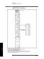
AMPLITUDE Y Scale Menu . . . . . . . . . . . . . . . . . . . . . . . . . . . . . . . . . . . . . . . . . . . . . . . . . . . . . 392
Amplitude Y Scale: Corrections Menu . . . . . . . . . . . . . . . . . . . . . . . . . . . . . . . . . . . . . . . . . . . . . . 393
Auto Couple Menu . . . . . . . . . . . . . . . . . . . . . . . . . . . . . . . . . . . . . . . . . . . . . . . . . . . . . . . . . . . . . . 394
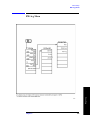
BW/Avg Menu . . . . . . . . . . . . . . . . . . . . . . . . . . . . . . . . . . . . . . . . . . . . . . . . . . . . . . . . . . . . . . . . . 395
Det/Demod Menu . . . . . . . . . . . . . . . . . . . . . . . . . . . . . . . . . . . . . . . . . . . . . . . . . . . . . . . . . . . . . . . 396
Display Menu . . . . . . . . . . . . . . . . . . . . . . . . . . . . . . . . . . . . . . . . . . . . . . . . . . . . . . . . . . . . . . . . . . 397
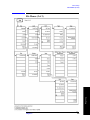
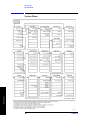
File Menus (1 of 3) . . . . . . . . . . . . . . . . . . . . . . . . . . . . . . . . . . . . . . . . . . . . . . . . . . . . . . . . . . . . . . 398
File Menus (2 of 3) . . . . . . . . . . . . . . . . . . . . . . . . . . . . . . . . . . . . . . . . . . . . . . . . . . . . . . . . . . . . . . 399
File Menus (3 of 3) . . . . . . . . . . . . . . . . . . . . . . . . . . . . . . . . . . . . . . . . . . . . . . . . . . . . . . . . . . . . . . 400
Freq Count (Marker) Menu . . . . . . . . . . . . . . . . . . . . . . . . . . . . . . . . . . . . . . . . . . . . . . . . . . . . . . . 401
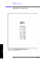
FREQUENCY Channel Menu . . . . . . . . . . . . . . . . . . . . . . . . . . . . . . . . . . . . . . . . . . . . . . . . . . . . . 402
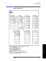
Input/Output Menu . . . . . . . . . . . . . . . . . . . . . . . . . . . . . . . . . . . . . . . . . . . . . . . . . . . . . . . . . . . . . . 403
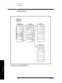
Marker Menu . . . . . . . . . . . . . . . . . . . . . . . . . . . . . . . . . . . . . . . . . . . . . . . . . . . . . . . . . . . . . . . . . . 404
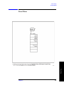
Marker → Menu . . . . . . . . . . . . . . . . . . . . . . . . . . . . . . . . . . . . . . . . . . . . . . . . . . . . . . . . . . . . . . . . 405
Peak Search Menu . . . . . . . . . . . . . . . . . . . . . . . . . . . . . . . . . . . . . . . . . . . . . . . . . . . . . . . . . . . . . . 406
Preset Menu . . . . . . . . . . . . . . . . . . . . . . . . . . . . . . . . . . . . . . . . . . . . . . . . . . . . . . . . . . . . . . . . . . . 407
Print Setup Menu . . . . . . . . . . . . . . . . . . . . . . . . . . . . . . . . . . . . . . . . . . . . . . . . . . . . . . . . . . . . . . . 408
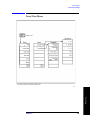
Source Menu. . . . . . . . . . . . . . . . . . . . . . . . . . . . . . . . . . . . . . . . . . . . . . . . . . . . . . . . . . . . . . . . . . . 409
SPAN (X Scale) Menu . . . . . . . . . . . . . . . . . . . . . . . . . . . . . . . . . . . . . . . . . . . . . . . . . . . . . . . . . . . 410
Sweep Menu . . . . . . . . . . . . . . . . . . . . . . . . . . . . . . . . . . . . . . . . . . . . . . . . . . . . . . . . . . . . . . . . . . . 411
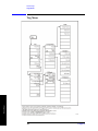
System Menu . . . . . . . . . . . . . . . . . . . . . . . . . . . . . . . . . . . . . . . . . . . . . . . . . . . . . . . . . . . . . . . . . . 412
Trace/View Menu . . . . . . . . . . . . . . . . . . . . . . . . . . . . . . . . . . . . . . . . . . . . . . . . . . . . . . . . . . . . . . . 413
Trig Menu . . . . . . . . . . . . . . . . . . . . . . . . . . . . . . . . . . . . . . . . . . . . . . . . . . . . . . . . . . . . . . . . . . . . . 414
16
List of Commands
:SOURce:POWer:ATTenuation <ampl> . . . . . . . . . . . . . . . . . . . . . . . . . . . . . . . . . . . . . . . . . . . . . . . . . . . . . . . . 343
*CAL? . . . . . . . . . . . . . . . . . . . . . . . . . . . . . . . . . . . . . . . . . . . . . . . . . . . . . . . . . . . . . . . . . . . . . . . . . . . . . . . . . . 231
*CLS. . . . . . . . . . . . . . . . . . . . . . . . . . . . . . . . . . . . . . . . . . . . . . . . . . . . . . . . . . . . . . . . . . . . . . . . . . . . . . . . . . . . 231
*CLS. . . . . . . . . . . . . . . . . . . . . . . . . . . . . . . . . . . . . . . . . . . . . . . . . . . . . . . . . . . . . . . . . . . . . . . . . . . . . . . . . . . . 234
*ESE <number> . . . . . . . . . . . . . . . . . . . . . . . . . . . . . . . . . . . . . . . . . . . . . . . . . . . . . . . . . . . . . . . . . . . . . . . . . . . 231
*ESE? . . . . . . . . . . . . . . . . . . . . . . . . . . . . . . . . . . . . . . . . . . . . . . . . . . . . . . . . . . . . . . . . . . . . . . . . . . . . . . . . . . . 231
*IDN? . . . . . . . . . . . . . . . . . . . . . . . . . . . . . . . . . . . . . . . . . . . . . . . . . . . . . . . . . . . . . . . . . . . . . . . . . . . . . . . . . . . 232
*LRN? . . . . . . . . . . . . . . . . . . . . . . . . . . . . . . . . . . . . . . . . . . . . . . . . . . . . . . . . . . . . . . . . . . . . . . . . . . . . . . . . . . 232
*OPC . . . . . . . . . . . . . . . . . . . . . . . . . . . . . . . . . . . . . . . . . . . . . . . . . . . . . . . . . . . . . . . . . . . . . . . . . . . . . . . . . . . 233
*OPC?. . . . . . . . . . . . . . . . . . . . . . . . . . . . . . . . . . . . . . . . . . . . . . . . . . . . . . . . . . . . . . . . . . . . . . . . . . . . . . . . . . . 233
*RCL <register>. . . . . . . . . . . . . . . . . . . . . . . . . . . . . . . . . . . . . . . . . . . . . . . . . . . . . . . . . . . . . . . . . . . . . . . . . . . 233
*RST. . . . . . . . . . . . . . . . . . . . . . . . . . . . . . . . . . . . . . . . . . . . . . . . . . . . . . . . . . . . . . . . . . . . . . . . . . . . . . . . . . . . 234
*RST. . . . . . . . . . . . . . . . . . . . . . . . . . . . . . . . . . . . . . . . . . . . . . . . . . . . . . . . . . . . . . . . . . . . . . . . . . . . . . . . . . . . 234
*RST. . . . . . . . . . . . . . . . . . . . . . . . . . . . . . . . . . . . . . . . . . . . . . . . . . . . . . . . . . . . . . . . . . . . . . . . . . . . . . . . . . . . 234
*SAV <register> . . . . . . . . . . . . . . . . . . . . . . . . . . . . . . . . . . . . . . . . . . . . . . . . . . . . . . . . . . . . . . . . . . . . . . . . . . . 234
*SRE <integer> . . . . . . . . . . . . . . . . . . . . . . . . . . . . . . . . . . . . . . . . . . . . . . . . . . . . . . . . . . . . . . . . . . . . . . . . . . . 235
*SRE? . . . . . . . . . . . . . . . . . . . . . . . . . . . . . . . . . . . . . . . . . . . . . . . . . . . . . . . . . . . . . . . . . . . . . . . . . . . . . . . . . . . 235
*STB? . . . . . . . . . . . . . . . . . . . . . . . . . . . . . . . . . . . . . . . . . . . . . . . . . . . . . . . . . . . . . . . . . . . . . . . . . . . . . . . . . . . 235
*TRG . . . . . . . . . . . . . . . . . . . . . . . . . . . . . . . . . . . . . . . . . . . . . . . . . . . . . . . . . . . . . . . . . . . . . . . . . . . . . . . . . . . 235
*TST? . . . . . . . . . . . . . . . . . . . . . . . . . . . . . . . . . . . . . . . . . . . . . . . . . . . . . . . . . . . . . . . . . . . . . . . . . . . . . . . . . . . 235
*WAI. . . . . . . . . . . . . . . . . . . . . . . . . . . . . . . . . . . . . . . . . . . . . . . . . . . . . . . . . . . . . . . . . . . . . . . . . . . . . . . . . . . . 235
:ABORt. . . . . . . . . . . . . . . . . . . . . . . . . . . . . . . . . . . . . . . . . . . . . . . . . . . . . . . . . . . . . . . . . . . . . . . . . . . . . . . . . . 236
:CALCulate:BWIDth|BANDwidth:NDB <rel_ampl> . . . . . . . . . . . . . . . . . . . . . . . . . . . . . . . . . . . . . . . . . . . . . . 237
:CALCulate:BWIDth|BANDwidth:NDB? . . . . . . . . . . . . . . . . . . . . . . . . . . . . . . . . . . . . . . . . . . . . . . . . . . . . . . . 237
:CALCulate:BWIDth|BANDwidth:RESult? . . . . . . . . . . . . . . . . . . . . . . . . . . . . . . . . . . . . . . . . . . . . . . . . . . . . . 237
:CALCulate:BWIDth|BANDwidth:RESult? . . . . . . . . . . . . . . . . . . . . . . . . . . . . . . . . . . . . . . . . . . . . . . . . . . . . . 237
:CALCulate:BWIDth|BANDwidth[:STATe] OFF|ON|0|1 . . . . . . . . . . . . . . . . . . . . . . . . . . . . . . . . . . . . . . . . . . . 238
:CALCulate:BWIDth|BANDwidth[:STATe]? . . . . . . . . . . . . . . . . . . . . . . . . . . . . . . . . . . . . . . . . . . . . . . . . . . . . 238
:CALCulate:CLIMits:FAIL? . . . . . . . . . . . . . . . . . . . . . . . . . . . . . . . . . . . . . . . . . . . . . . . . . . . . . . . . . . . . . . . . . 238
:CALCulate:LLINe:ALL:DELete . . . . . . . . . . . . . . . . . . . . . . . . . . . . . . . . . . . . . . . . . . . . . . . . . . . . . . . . . . . . . 239
17
List of Commands
*ESR? . . . . . . . . . . . . . . . . . . . . . . . . . . . . . . . . . . . . . . . . . . . . . . . . . . . . . . . . . . . . . . . . . . . . . . . . . . . . . . . . . . . 232
List of Commands
:CALCulate:LLINe:CMODe FIXed|RELative . . . . . . . . . . . . . . . . . . . . . . . . . . . . . . . . . . . . . . . . . . . . . . . . . . . 239
:CALCulate:LLINe:CMODe? . . . . . . . . . . . . . . . . . . . . . . . . . . . . . . . . . . . . . . . . . . . . . . . . . . . . . . . . . . . . . . . . 239
:CALCulate:LLINe:CONTrol:DOMain FREQuency|TIME . . . . . . . . . . . . . . . . . . . . . . . . . . . . . . . . . . . . . . . . . 240
:CALCulate:LLINe:CONTrol:DOMain TIME . . . . . . . . . . . . . . . . . . . . . . . . . . . . . . . . . . . . . . . . . . . . . . . . . . . 241
:CALCulate:LLINe:CONTrol:DOMain?. . . . . . . . . . . . . . . . . . . . . . . . . . . . . . . . . . . . . . . . . . . . . . . . . . . . . . . . 240
List of Commands
:CALCulate:LLINe[1]|2:AMPLitude:INTerpolate:TYPE LOGarithmic|LINear . . . . . . . . . . . . . . . . . . . . . . . . . 239
:CALCulate:LLINe[1]|2:AMPLitude:INTerpolate:TYPE? . . . . . . . . . . . . . . . . . . . . . . . . . . . . . . . . . . . . . . . . . . 239
:CALCulate:LLINe[1]|2:CONTrol:INTerpolate:TYPE LOGarithmic . . . . . . . . . . . . . . . . . . . . . . . . . . . . . . . . . 241
:CALCulate:LLINe[1]|2:CONTrol:INTerpolate:TYPE LOGarithmic|LINear . . . . . . . . . . . . . . . . . . . . . . . . . . . 241
:CALCulate:LLINe[1]|2:CONTrol:INTerpolate:TYPE? . . . . . . . . . . . . . . . . . . . . . . . . . . . . . . . . . . . . . . . . . . . . 241
:CALCulate:LLINe[1]|2:DATA <x-axis>,<ampl>,<connected>{,<x-axis>,<ampl>,<connected>} . . . . . . . . . . 241
:CALCulate:LLINe[1]|2:DATA:MERGe <x-axis>,<ampl>,<connected>{,<x-axis>,<ampl>,<connected>} . . . 243
:CALCulate:LLINe[1]|2:DATA? . . . . . . . . . . . . . . . . . . . . . . . . . . . . . . . . . . . . . . . . . . . . . . . . . . . . . . . . . . . . . . 241
:CALCulate:LLINe[1]|2:DELete . . . . . . . . . . . . . . . . . . . . . . . . . . . . . . . . . . . . . . . . . . . . . . . . . . . . . . . . . . . . . . 243
:CALCulate:LLINe[1]|2:DISPlay OFF|ON|0|1 . . . . . . . . . . . . . . . . . . . . . . . . . . . . . . . . . . . . . . . . . . . . . . . . . . . 244
:CALCulate:LLINe[1]|2:DISPlay? . . . . . . . . . . . . . . . . . . . . . . . . . . . . . . . . . . . . . . . . . . . . . . . . . . . . . . . . . . . . 244
:CALCulate:LLINe[1]|2:FAIL? . . . . . . . . . . . . . . . . . . . . . . . . . . . . . . . . . . . . . . . . . . . . . . . . . . . . . . . . . . . . . . . 244
:CALCulate:LLINe[1]|2:MARGin <rel_ampl>. . . . . . . . . . . . . . . . . . . . . . . . . . . . . . . . . . . . . . . . . . . . . . . . . . . 244
:CALCulate:LLINe[1]|2:MARGin:STATe OFF|ON|0|1 . . . . . . . . . . . . . . . . . . . . . . . . . . . . . . . . . . . . . . . . . . . . 244
:CALCulate:LLINe[1]|2:MARGin:STATe?. . . . . . . . . . . . . . . . . . . . . . . . . . . . . . . . . . . . . . . . . . . . . . . . . . . . . . 244
:CALCulate:LLINe[1]|2:MARGin?. . . . . . . . . . . . . . . . . . . . . . . . . . . . . . . . . . . . . . . . . . . . . . . . . . . . . . . . . . . . 244
:CALCulate:LLINe[1]|2:STATe OFF|ON|0|1 . . . . . . . . . . . . . . . . . . . . . . . . . . . . . . . . . . . . . . . . . . . . . . . . . . . . 245
:CALCulate:LLINe[1]|2:STATe? . . . . . . . . . . . . . . . . . . . . . . . . . . . . . . . . . . . . . . . . . . . . . . . . . . . . . . . . . . . . . . 245
:CALCulate:LLINe[1]|2:TYPE UPPer|LOWer . . . . . . . . . . . . . . . . . . . . . . . . . . . . . . . . . . . . . . . . . . . . . . . . . . . 245
:CALCulate:LLINe[1]|2:TYPE? . . . . . . . . . . . . . . . . . . . . . . . . . . . . . . . . . . . . . . . . . . . . . . . . . . . . . . . . . . . . . . 245
:CALCulate:MARKer:AOFF. . . . . . . . . . . . . . . . . . . . . . . . . . . . . . . . . . . . . . . . . . . . . . . . . . . . . . . . . . . . . . . . . 246
:CALCulate:MARKer:FCOunt:RESolution <real>. . . . . . . . . . . . . . . . . . . . . . . . . . . . . . . . . . . . . . . . . . . . . . . . 246
:CALCulate:MARKer:FCOunt:RESolution:AUTO OFF|ON|0|1 . . . . . . . . . . . . . . . . . . . . . . . . . . . . . . . . . . . . . 247
:CALCulate:MARKer:FCOunt:RESolution:AUTO? . . . . . . . . . . . . . . . . . . . . . . . . . . . . . . . . . . . . . . . . . . . . . . 247
:CALCulate:MARKer:FCOunt:RESolution? . . . . . . . . . . . . . . . . . . . . . . . . . . . . . . . . . . . . . . . . . . . . . . . . . . . . 246
:CALCulate:MARKer:MODE SPAN . . . . . . . . . . . . . . . . . . . . . . . . . . . . . . . . . . . . . . . . . . . . . . . . . . . . . . . . . . 258
18
List of Commands
:CALCulate:MARKer:PEAK: . . . . . . . . . . . . . . . . . . . . . . . . . . . . . . . . . . . . . . . . . . . . . . . . . . . . . . . . . . . . . . . . 251
:CALCulate:MARKer:PEAK:EXCursion <rel_ampl> . . . . . . . . . . . . . . . . . . . . . . . . . . . . . . . . . . . . . . . . . . . . . 250
:CALCulate:MARKer:PEAK:EXCursion? . . . . . . . . . . . . . . . . . . . . . . . . . . . . . . . . . . . . . . . . . . . . . . . . . . . . . . 250
:CALCulate:MARKer:PEAK:SEARch:MODE PARameter|MAXimum . . . . . . . . . . . . . . . . . . . . . . . . . . . . . . . 251
:CALCulate:MARKer:PEAK:THReshold <ampl> . . . . . . . . . . . . . . . . . . . . . . . . . . . . . . . . . . . . . . . . . . . . . . . . 251
:CALCulate:MARKer:PEAK:THReshold? . . . . . . . . . . . . . . . . . . . . . . . . . . . . . . . . . . . . . . . . . . . . . . . . . . . . . . 251
:CALCulate:MARKer:TABLe:STATe? . . . . . . . . . . . . . . . . . . . . . . . . . . . . . . . . . . . . . . . . . . . . . . . . . . . . . . . . . 253
:CALCulate:MARKer[1]:FCOunt:X? . . . . . . . . . . . . . . . . . . . . . . . . . . . . . . . . . . . . . . . . . . . . . . . . . . . . . . . . . . 247
:CALCulate:MARKer[1]|2|3|4:CPEak[:STATe] OFF|ON|0|1 . . . . . . . . . . . . . . . . . . . . . . . . . . . . . . . . . . . . . . . . 246
:CALCulate:MARKer[1]|2|3|4:CPEak[:STATe]?. . . . . . . . . . . . . . . . . . . . . . . . . . . . . . . . . . . . . . . . . . . . . . . . . . 246
:CALCulate:MARKer[1]|2|3|4:FCOunt:X? . . . . . . . . . . . . . . . . . . . . . . . . . . . . . . . . . . . . . . . . . . . . . . . . . . . . . . 247
:CALCulate:MARKer[1]|2|3|4:FCOunt[:STATe] OFF|ON|0|1 . . . . . . . . . . . . . . . . . . . . . . . . . . . . . . . . . . . . . . . 247
:CALCulate:MARKer[1]|2|3|4:FCOunt[:STATe]? . . . . . . . . . . . . . . . . . . . . . . . . . . . . . . . . . . . . . . . . . . . . . . . . . 247
:CALCulate:MARKer[1]|2|3|4:FUNCtion BPOWer|NOISe|OFF . . . . . . . . . . . . . . . . . . . . . . . . . . . . . . . . . . . . . 248
:CALCulate:MARKer[1]|2|3|4:FUNCtion? . . . . . . . . . . . . . . . . . . . . . . . . . . . . . . . . . . . . . . . . . . . . . . . . . . . . . . 248
:CALCulate:MARKer[1]|2|3|4:MAXimum . . . . . . . . . . . . . . . . . . . . . . . . . . . . . . . . . . . . . . . . . . . . . . . . . . . . . . 248
:CALCulate:MARKer[1]|2|3|4:MAXimum:LEFT. . . . . . . . . . . . . . . . . . . . . . . . . . . . . . . . . . . . . . . . . . . . . . . . . 248
:CALCulate:MARKer[1]|2|3|4:MAXimum:NEXT . . . . . . . . . . . . . . . . . . . . . . . . . . . . . . . . . . . . . . . . . . . . . . . . 249
:CALCulate:MARKer[1]|2|3|4:MAXimum:RIGHt . . . . . . . . . . . . . . . . . . . . . . . . . . . . . . . . . . . . . . . . . . . . . . . . 249
:CALCulate:MARKer[1]|2|3|4:MINimum . . . . . . . . . . . . . . . . . . . . . . . . . . . . . . . . . . . . . . . . . . . . . . . . . . . . . . . 249
:CALCulate:MARKer[1]|2|3|4:MODE POSition|DELTa|BAND|SPAN . . . . . . . . . . . . . . . . . . . . . . . . . . . . . . . . 249
:CALCulate:MARKer[1]|2|3|4:MODE?. . . . . . . . . . . . . . . . . . . . . . . . . . . . . . . . . . . . . . . . . . . . . . . . . . . . . . . . . 249
:CALCulate:MARKer[1]|2|3|4:PTPeak . . . . . . . . . . . . . . . . . . . . . . . . . . . . . . . . . . . . . . . . . . . . . . . . . . . . . . . . . 251
:CALCulate:MARKer[1]|2|3|4:STATe OFF|ON|0|1. . . . . . . . . . . . . . . . . . . . . . . . . . . . . . . . . . . . . . . . . . . . . . . . 253
:CALCulate:MARKer[1]|2|3|4:STATe? . . . . . . . . . . . . . . . . . . . . . . . . . . . . . . . . . . . . . . . . . . . . . . . . . . . . . . . . . 253
:CALCulate:MARKer[1]|2|3|4:TRACe <integer> . . . . . . . . . . . . . . . . . . . . . . . . . . . . . . . . . . . . . . . . . . . . . . . . . 254
:CALCulate:MARKer[1]|2|3|4:TRACe:AUTO OFF|ON|0|1 . . . . . . . . . . . . . . . . . . . . . . . . . . . . . . . . . . . . . . . . . 254
:CALCulate:MARKer[1]|2|3|4:TRACe:AUTO? . . . . . . . . . . . . . . . . . . . . . . . . . . . . . . . . . . . . . . . . . . . . . . . . . . 254
:CALCulate:MARKer[1]|2|3|4:TRACe? . . . . . . . . . . . . . . . . . . . . . . . . . . . . . . . . . . . . . . . . . . . . . . . . . . . . . . . . 254
:CALCulate:MARKer[1]|2|3|4:TRCKing[:STATe] OFF|ON|0|1 . . . . . . . . . . . . . . . . . . . . . . . . . . . . . . . . . . . . . . 254
19
List of Commands
:CALCulate:MARKer:TABLe:STATe OFF|ON|0|1 . . . . . . . . . . . . . . . . . . . . . . . . . . . . . . . . . . . . . . . . . . . . . . . . 253
List of Commands
:CALCulate:MARKer[1]|2|3|4:TRCKing[:STATe]? . . . . . . . . . . . . . . . . . . . . . . . . . . . . . . . . . . . . . . . . . . . . . . . 254
:CALCulate:MARKer[1]|2|3|4:X <param> . . . . . . . . . . . . . . . . . . . . . . . . . . . . . . . . . . . . . . . . . . . . . . . . . . . . . . 255
:CALCulate:MARKer[1]|2|3|4:X:CENTer <param> . . . . . . . . . . . . . . . . . . . . . . . . . . . . . . . . . . . . . . . . . . . . . . . 255
:CALCulate:MARKer[1]|2|3|4:X:CENTer?. . . . . . . . . . . . . . . . . . . . . . . . . . . . . . . . . . . . . . . . . . . . . . . . . . . . . . 255
:CALCulate:MARKer[1]|2|3|4:X:POSition <integer> . . . . . . . . . . . . . . . . . . . . . . . . . . . . . . . . . . . . . . . . . . . . . 255
List of Commands
:CALCulate:MARKer[1]|2|3|4:X:POSition:CENTer <param> . . . . . . . . . . . . . . . . . . . . . . . . . . . . . . . . . . . . . . . 256
:CALCulate:MARKer[1]|2|3|4:X:POSition:CENTer?. . . . . . . . . . . . . . . . . . . . . . . . . . . . . . . . . . . . . . . . . . . . . . 256
:CALCulate:MARKer[1]|2|3|4:X:POSition:SPAN <param>. . . . . . . . . . . . . . . . . . . . . . . . . . . . . . . . . . . . . . . . . 256
:CALCulate:MARKer[1]|2|3|4:X:POSition:SPAN? . . . . . . . . . . . . . . . . . . . . . . . . . . . . . . . . . . . . . . . . . . . . . . . 256
:CALCulate:MARKer[1]|2|3|4:X:POSition:STARt <param> . . . . . . . . . . . . . . . . . . . . . . . . . . . . . . . . . . . . . . . . 256
:CALCulate:MARKer[1]|2|3|4:X:POSition:STARt? . . . . . . . . . . . . . . . . . . . . . . . . . . . . . . . . . . . . . . . . . . . . . . . 256
:CALCulate:MARKer[1]|2|3|4:X:POSition:STOP <param>. . . . . . . . . . . . . . . . . . . . . . . . . . . . . . . . . . . . . . . . . 257
:CALCulate:MARKer[1]|2|3|4:X:POSition:STOP? . . . . . . . . . . . . . . . . . . . . . . . . . . . . . . . . . . . . . . . . . . . . . . . 257
:CALCulate:MARKer[1]|2|3|4:X:POSition? . . . . . . . . . . . . . . . . . . . . . . . . . . . . . . . . . . . . . . . . . . . . . . . . . . . . . 255
:CALCulate:MARKer[1]|2|3|4:X:READout FREQuency|TIME|ITIMe|PERiod . . . . . . . . . . . . . . . . . . . . . . . . . 257
:CALCulate:MARKer[1]|2|3|4:X:READout? . . . . . . . . . . . . . . . . . . . . . . . . . . . . . . . . . . . . . . . . . . . . . . . . . . . . 257
:CALCulate:MARKer[1]|2|3|4:X:SPAN <param> . . . . . . . . . . . . . . . . . . . . . . . . . . . . . . . . . . . . . . . . . . . . . . . . 258
:CALCulate:MARKer[1]|2|3|4:X:SPAN? . . . . . . . . . . . . . . . . . . . . . . . . . . . . . . . . . . . . . . . . . . . . . . . . . . . . . . . 258
:CALCulate:MARKer[1]|2|3|4:X:STARt <param> . . . . . . . . . . . . . . . . . . . . . . . . . . . . . . . . . . . . . . . . . . . . . . . . 258
:CALCulate:MARKer[1]|2|3|4:X:STARt? . . . . . . . . . . . . . . . . . . . . . . . . . . . . . . . . . . . . . . . . . . . . . . . . . . . . . . . 258
:CALCulate:MARKer[1]|2|3|4:X:STOP <param>. . . . . . . . . . . . . . . . . . . . . . . . . . . . . . . . . . . . . . . . . . . . . . . . . 258
:CALCulate:MARKer[1]|2|3|4:X:STOP? . . . . . . . . . . . . . . . . . . . . . . . . . . . . . . . . . . . . . . . . . . . . . . . . . . . . . . . 258
:CALCulate:MARKer[1]|2|3|4:X? . . . . . . . . . . . . . . . . . . . . . . . . . . . . . . . . . . . . . . . . . . . . . . . . . . . . . . . . . . . . . 255
:CALCulate:MARKer[1]|2|3|4:Y? . . . . . . . . . . . . . . . . . . . . . . . . . . . . . . . . . . . . . . . . . . . . . . . . . . . . . . . . . . . . . 259
:CALCulate:MARKer[1]|2|3|4[:SET]:CENTer . . . . . . . . . . . . . . . . . . . . . . . . . . . . . . . . . . . . . . . . . . . . . . . . . . . 252
:CALCulate:MARKer[1]|2|3|4[:SET]:RLEVel . . . . . . . . . . . . . . . . . . . . . . . . . . . . . . . . . . . . . . . . . . . . . . . . . . . 252
:CALCulate:MARKer[1]|2|3|4[:SET]:SPAN . . . . . . . . . . . . . . . . . . . . . . . . . . . . . . . . . . . . . . . . . . . . . . . . . . . . . 252
:CALCulate:MARKer[1]|2|3|4[:SET]:STARt . . . . . . . . . . . . . . . . . . . . . . . . . . . . . . . . . . . . . . . . . . . . . . . . . . . . 252
:CALCulate:MARKer[1]|2|3|4[:SET]:STEP . . . . . . . . . . . . . . . . . . . . . . . . . . . . . . . . . . . . . . . . . . . . . . . . . . . . . 253
:CALCulate:MARKer[1]|2|3|4[:SET]:STOP . . . . . . . . . . . . . . . . . . . . . . . . . . . . . . . . . . . . . . . . . . . . . . . . . . . . . 253
:CALCulate:NTData[:STATe] OFF|ON|0|1 . . . . . . . . . . . . . . . . . . . . . . . . . . . . . . . . . . . . . . . . . . . . . . . . . . . . . . 260
20
List of Commands
:CALCulate:NTData[:STATe]? . . . . . . . . . . . . . . . . . . . . . . . . . . . . . . . . . . . . . . . . . . . . . . . . . . . . . . . . . . . . . . . 260
:CALibration:AUTO OFF|ON|0|1 . . . . . . . . . . . . . . . . . . . . . . . . . . . . . . . . . . . . . . . . . . . . . . . . . . . . . . . . . . . . . 262
:CALibration:AUTO:MODE ALL|NRF . . . . . . . . . . . . . . . . . . . . . . . . . . . . . . . . . . . . . . . . . . . . . . . . . . . . . . . . 261
:CALibration:AUTO:MODE? . . . . . . . . . . . . . . . . . . . . . . . . . . . . . . . . . . . . . . . . . . . . . . . . . . . . . . . . . . . . . . . . 261
:CALibration:AUTO?. . . . . . . . . . . . . . . . . . . . . . . . . . . . . . . . . . . . . . . . . . . . . . . . . . . . . . . . . . . . . . . . . . . . . . . 262
:CALibration:DATA:DEFault . . . . . . . . . . . . . . . . . . . . . . . . . . . . . . . . . . . . . . . . . . . . . . . . . . . . . . . . . . . . . . . . 262
:CALibration:FMDemod? . . . . . . . . . . . . . . . . . . . . . . . . . . . . . . . . . . . . . . . . . . . . . . . . . . . . . . . . . . . . . . . . . . . 262
:CALibration:FREQuency:REFerence:COARse <setting> . . . . . . . . . . . . . . . . . . . . . . . . . . . . . . . . . . . . . . . . . . 263
:CALibration:FREQuency:REFerence:COARse? . . . . . . . . . . . . . . . . . . . . . . . . . . . . . . . . . . . . . . . . . . . . . . . . . 263
:CALibration:FREQuency:REFerence:FINE <setting>. . . . . . . . . . . . . . . . . . . . . . . . . . . . . . . . . . . . . . . . . . . . . 263
:CALibration:FREQuency:REFerence:FINE? . . . . . . . . . . . . . . . . . . . . . . . . . . . . . . . . . . . . . . . . . . . . . . . . . . . . 263
:CALibration:FREQuency:REFerence? . . . . . . . . . . . . . . . . . . . . . . . . . . . . . . . . . . . . . . . . . . . . . . . . . . . . . . . . . 263
:CALibration:FREQuency[:STATe] OFF|ON|0|1. . . . . . . . . . . . . . . . . . . . . . . . . . . . . . . . . . . . . . . . . . . . . . . . . . 263
:CALibration:FREQuency[:STATe]? . . . . . . . . . . . . . . . . . . . . . . . . . . . . . . . . . . . . . . . . . . . . . . . . . . . . . . . . . . . 263
:CALibration:RF. . . . . . . . . . . . . . . . . . . . . . . . . . . . . . . . . . . . . . . . . . . . . . . . . . . . . . . . . . . . . . . . . . . . . . . . . . . 264
:CALibration:RF?. . . . . . . . . . . . . . . . . . . . . . . . . . . . . . . . . . . . . . . . . . . . . . . . . . . . . . . . . . . . . . . . . . . . . . . . . . 264
:CALibration:SOURce:STATe OFF|ON|0|1. . . . . . . . . . . . . . . . . . . . . . . . . . . . . . . . . . . . . . . . . . . . . . . . . . . . . . 264
:CALibration:SOURce:STATe? . . . . . . . . . . . . . . . . . . . . . . . . . . . . . . . . . . . . . . . . . . . . . . . . . . . . . . . . . . . . . . . 264
:CALibration:TG . . . . . . . . . . . . . . . . . . . . . . . . . . . . . . . . . . . . . . . . . . . . . . . . . . . . . . . . . . . . . . . . . . . . . . . . . . 265
:CALibration:TG? . . . . . . . . . . . . . . . . . . . . . . . . . . . . . . . . . . . . . . . . . . . . . . . . . . . . . . . . . . . . . . . . . . . . . . . . . 265
:CALibration[:ALL] . . . . . . . . . . . . . . . . . . . . . . . . . . . . . . . . . . . . . . . . . . . . . . . . . . . . . . . . . . . . . . . . . . . . . . . . 261
:CALibration[:ALL]? . . . . . . . . . . . . . . . . . . . . . . . . . . . . . . . . . . . . . . . . . . . . . . . . . . . . . . . . . . . . . . . . . . . . . . . 261
:COUPle ALL|NONE. . . . . . . . . . . . . . . . . . . . . . . . . . . . . . . . . . . . . . . . . . . . . . . . . . . . . . . . . . . . . . . . . . . . . . . 267
:COUPle? . . . . . . . . . . . . . . . . . . . . . . . . . . . . . . . . . . . . . . . . . . . . . . . . . . . . . . . . . . . . . . . . . . . . . . . . . . . . . . . . 267
:DISPlay:AFUNction:POSition BOTTom|CENTer|TOP . . . . . . . . . . . . . . . . . . . . . . . . . . . . . . . . . . . . . . . . . . . . 269
:DISPlay:AFUNction:POSition? . . . . . . . . . . . . . . . . . . . . . . . . . . . . . . . . . . . . . . . . . . . . . . . . . . . . . . . . . . . . . . 269
:DISPlay:ANGLe <integer>. . . . . . . . . . . . . . . . . . . . . . . . . . . . . . . . . . . . . . . . . . . . . . . . . . . . . . . . . . . . . . . . . . 269
:DISPlay:ANGLe? . . . . . . . . . . . . . . . . . . . . . . . . . . . . . . . . . . . . . . . . . . . . . . . . . . . . . . . . . . . . . . . . . . . . . . . . . 269
:DISPlay:ANNotation:CLOCk:DATE:FORMat MDY|DMY . . . . . . . . . . . . . . . . . . . . . . . . . . . . . . . . . . . . . . . . 269
:DISPlay:ANNotation:CLOCk:DATE:FORMat? . . . . . . . . . . . . . . . . . . . . . . . . . . . . . . . . . . . . . . . . . . . . . . . . . 269
21
List of Commands
:CALibration:FMDemod . . . . . . . . . . . . . . . . . . . . . . . . . . . . . . . . . . . . . . . . . . . . . . . . . . . . . . . . . . . . . . . . . . . . 262
List of Commands
:DISPlay:ANNotation:CLOCk[:STATe] OFF|ON|0|1 . . . . . . . . . . . . . . . . . . . . . . . . . . . . . . . . . . . . . . . . . . . . . . 270
:DISPlay:ANNotation:CLOCk[:STATe]? . . . . . . . . . . . . . . . . . . . . . . . . . . . . . . . . . . . . . . . . . . . . . . . . . . . . . . . 270
:DISPlay:ANNotation:TITLe:DATA <string> . . . . . . . . . . . . . . . . . . . . . . . . . . . . . . . . . . . . . . . . . . . . . . . . . . . 270
:DISPlay:ANNotation:TITLe:DATA? . . . . . . . . . . . . . . . . . . . . . . . . . . . . . . . . . . . . . . . . . . . . . . . . . . . . . . . . . . 270
:DISPlay:ENABle OFF|ON|0|1 . . . . . . . . . . . . . . . . . . . . . . . . . . . . . . . . . . . . . . . . . . . . . . . . . . . . . . . . . . . . . . . 270
List of Commands
:DISPlay:MENU:STATe OFF|ON|0|1 . . . . . . . . . . . . . . . . . . . . . . . . . . . . . . . . . . . . . . . . . . . . . . . . . . . . . . . . . . 271
:DISPlay:MENU:STATe?. . . . . . . . . . . . . . . . . . . . . . . . . . . . . . . . . . . . . . . . . . . . . . . . . . . . . . . . . . . . . . . . . . . . 271
:DISPlay:WINDow:ANNotation[:ALL] OFF|ON|0|1 . . . . . . . . . . . . . . . . . . . . . . . . . . . . . . . . . . . . . . . . . . . . . . 271
:DISPlay:WINDow:ANNotation[:ALL]? . . . . . . . . . . . . . . . . . . . . . . . . . . . . . . . . . . . . . . . . . . . . . . . . . . . . . . . 271
:DISPlay:WINDow:TRACe:GRATicule:GRID[:STATe] OFF|ON|0|1 . . . . . . . . . . . . . . . . . . . . . . . . . . . . . . . . . 271
:DISPlay:WINDow:TRACe:GRATicule:GRID[:STATe]? . . . . . . . . . . . . . . . . . . . . . . . . . . . . . . . . . . . . . . . . . . 271
:DISPlay:WINDow:TRACe:X[:SCALe]:OFFSet <freq> . . . . . . . . . . . . . . . . . . . . . . . . . . . . . . . . . . . . . . . . . . . 271
:DISPlay:WINDow:TRACe:X[:SCALe]:OFFSet? . . . . . . . . . . . . . . . . . . . . . . . . . . . . . . . . . . . . . . . . . . . . . . . . 272
:DISPlay:WINDow:TRACe:Y:DLINe <ampl> . . . . . . . . . . . . . . . . . . . . . . . . . . . . . . . . . . . . . . . . . . . . . . . . . . . 272
:DISPlay:WINDow:TRACe:Y:DLINe:STATe OFF|ON|0|1 . . . . . . . . . . . . . . . . . . . . . . . . . . . . . . . . . . . . . . . . . 272
:DISPlay:WINDow:TRACe:Y:DLINe:STATe?. . . . . . . . . . . . . . . . . . . . . . . . . . . . . . . . . . . . . . . . . . . . . . . . . . . 272
:DISPlay:WINDow:TRACe:Y:DLINe?. . . . . . . . . . . . . . . . . . . . . . . . . . . . . . . . . . . . . . . . . . . . . . . . . . . . . . . . . 272
:DISPlay:WINDow:TRACe:Y[:SCALe]:NRLevel <rel_ampl> . . . . . . . . . . . . . . . . . . . . . . . . . . . . . . . . . . . . . . 273
:DISPlay:WINDow:TRACe:Y[:SCALe]:NRLevel? . . . . . . . . . . . . . . . . . . . . . . . . . . . . . . . . . . . . . . . . . . . . . . . 273
:DISPlay:WINDow:TRACe:Y[:SCALe]:NRPosition <integer> . . . . . . . . . . . . . . . . . . . . . . . . . . . . . . . . . . . . . 274
:DISPlay:WINDow:TRACe:Y[:SCALe]:NRPosition? . . . . . . . . . . . . . . . . . . . . . . . . . . . . . . . . . . . . . . . . . . . . . 274
:DISPlay:WINDow:TRACe:Y[:SCALe]:PDIVision <rel_ampl> . . . . . . . . . . . . . . . . . . . . . . . . . . . . . . . . . . . . . 274
:DISPlay:WINDow:TRACe:Y[:SCALe]:PDIVision:FREQuency . . . . . . . . . . . . . . . . . . . . . . . . . . . . . . . . . . . . 274
:DISPlay:WINDow:TRACe:Y[:SCALe]:PDIVision:FREQuency? . . . . . . . . . . . . . . . . . . . . . . . . . . . . . . . . . . . 274
:DISPlay:WINDow:TRACe:Y[:SCALe]:PDIVision? . . . . . . . . . . . . . . . . . . . . . . . . . . . . . . . . . . . . . . . . . . . . . . 274
:DISPlay:WINDow:TRACe:Y[:SCALe]:RLEVel <ampl> . . . . . . . . . . . . . . . . . . . . . . . . . . . . . . . . . . . . . . . . . . 275
:DISPlay:WINDow:TRACe:Y[:SCALe]:RLEVel:OFFSet <rel_ampl> . . . . . . . . . . . . . . . . . . . . . . . . . . . . . . . . 276
:DISPlay:WINDow:TRACe:Y[:SCALe]:RLEVel:OFFSet? . . . . . . . . . . . . . . . . . . . . . . . . . . . . . . . . . . . . . . . . . 276
:DISPlay:WINDow:TRACe:Y[:SCALe]:RLEVel? . . . . . . . . . . . . . . . . . . . . . . . . . . . . . . . . . . . . . . . . . . . . . . . . 275
:DISPlay:WINDow:TRACe:Y[:SCALe]:SPACing LINear|LOGarithmic . . . . . . . . . . . . . . . . . . . . . . . . . . . . . . 277
:DISPlay:WINDow:TRACe:Y[:SCALe]:SPACing? . . . . . . . . . . . . . . . . . . . . . . . . . . . . . . . . . . . . . . . . . . . . . . . 277
22
List of Commands
:FORMat:BORDer NORMal|SWAPped . . . . . . . . . . . . . . . . . . . . . . . . . . . . . . . . . . . . . . . . . . . . . . . . . . . . . . . . 278
:FORMat:BORDer? . . . . . . . . . . . . . . . . . . . . . . . . . . . . . . . . . . . . . . . . . . . . . . . . . . . . . . . . . . . . . . . . . . . . . . . . 278
:FORMat[:TRACe][:DATA]?. . . . . . . . . . . . . . . . . . . . . . . . . . . . . . . . . . . . . . . . . . . . . . . . . . . . . . . . . . . . . . . . . 278
:FORMat[:TRACe][:DATA]ASCii|INTeger,32|REAL,32|
REAL,64|UINTeger,16. . . . . . . . . . . . . . . . . . . . . . . . . . . . . . . . . . . . . . . . . . . . . . . . . . . . . . . . . . . . . . . . . . . . . . 278
:HCOPy:ABORt . . . . . . . . . . . . . . . . . . . . . . . . . . . . . . . . . . . . . . . . . . . . . . . . . . . . . . . . . . . . . . . . . . . . . . . . . . . 281
:HCOPy:DEVice:TYPE AUTO|CUSTom|NONE . . . . . . . . . . . . . . . . . . . . . . . . . . . . . . . . . . . . . . . . . . . . . . . . . 281
:HCOPy:IMAGe:COLor[:STATe] OFF|ON|0|1 . . . . . . . . . . . . . . . . . . . . . . . . . . . . . . . . . . . . . . . . . . . . . . . . . . . 281
:HCOPy:IMAGe:COLor[:STATe]? . . . . . . . . . . . . . . . . . . . . . . . . . . . . . . . . . . . . . . . . . . . . . . . . . . . . . . . . . . . . 281
:HCOPy:ITEM:FFEed[:IMMediate] . . . . . . . . . . . . . . . . . . . . . . . . . . . . . . . . . . . . . . . . . . . . . . . . . . . . . . . . . . . 282
:HCOPy:PAGE:ORIentation LANDscape|PORTrait . . . . . . . . . . . . . . . . . . . . . . . . . . . . . . . . . . . . . . . . . . . . . . . 282
:HCOPy:PAGE:ORIentation? . . . . . . . . . . . . . . . . . . . . . . . . . . . . . . . . . . . . . . . . . . . . . . . . . . . . . . . . . . . . . . . . 282
:HCOPy:PAGE:PRINts <integer> . . . . . . . . . . . . . . . . . . . . . . . . . . . . . . . . . . . . . . . . . . . . . . . . . . . . . . . . . . . . . 282
:HCOPy:PAGE:PRINts? . . . . . . . . . . . . . . . . . . . . . . . . . . . . . . . . . . . . . . . . . . . . . . . . . . . . . . . . . . . . . . . . . . . . 282
:HCOPy:PAGE:SIZE A|B|A3|A4|LETTer|LEGal|EXECutive|LEDGer . . . . . . . . . . . . . . . . . . . . . . . . . . . . . . . . 283
:HCOPy:PAGE:SIZE? . . . . . . . . . . . . . . . . . . . . . . . . . . . . . . . . . . . . . . . . . . . . . . . . . . . . . . . . . . . . . . . . . . . . . . 283
:HCOPy[:IMMediate]. . . . . . . . . . . . . . . . . . . . . . . . . . . . . . . . . . . . . . . . . . . . . . . . . . . . . . . . . . . . . . . . . . . . . . . 282
:INITiate:CONTinuous OFF|ON|0|1 . . . . . . . . . . . . . . . . . . . . . . . . . . . . . . . . . . . . . . . . . . . . . . . . . . . . . . . . . . . 284
:INITiate:CONTinuous? . . . . . . . . . . . . . . . . . . . . . . . . . . . . . . . . . . . . . . . . . . . . . . . . . . . . . . . . . . . . . . . . . . . . . 284
:INITiate:PAUSe. . . . . . . . . . . . . . . . . . . . . . . . . . . . . . . . . . . . . . . . . . . . . . . . . . . . . . . . . . . . . . . . . . . . . . . . . . . 285
:INITiate:RESTart. . . . . . . . . . . . . . . . . . . . . . . . . . . . . . . . . . . . . . . . . . . . . . . . . . . . . . . . . . . . . . . . . . . . . . . . . . 286
:INITiate:RESume . . . . . . . . . . . . . . . . . . . . . . . . . . . . . . . . . . . . . . . . . . . . . . . . . . . . . . . . . . . . . . . . . . . . . . . . . 286
:INITiate[:IMMediate] . . . . . . . . . . . . . . . . . . . . . . . . . . . . . . . . . . . . . . . . . . . . . . . . . . . . . . . . . . . . . . . . . . . . . . 285
:INPut:COUPling AC|DC . . . . . . . . . . . . . . . . . . . . . . . . . . . . . . . . . . . . . . . . . . . . . . . . . . . . . . . . . . . . . . . . . . . 287
:INPut:COUPling? . . . . . . . . . . . . . . . . . . . . . . . . . . . . . . . . . . . . . . . . . . . . . . . . . . . . . . . . . . . . . . . . . . . . . . . . . 287
:INPut:PROTection:CLEar. . . . . . . . . . . . . . . . . . . . . . . . . . . . . . . . . . . . . . . . . . . . . . . . . . . . . . . . . . . . . . . . . . . 289
:INSTrument:CATalog? . . . . . . . . . . . . . . . . . . . . . . . . . . . . . . . . . . . . . . . . . . . . . . . . . . . . . . . . . . . . . . . . . . . . . 290
:INSTrument:NSELect <integer> . . . . . . . . . . . . . . . . . . . . . . . . . . . . . . . . . . . . . . . . . . . . . . . . . . . . . . . . . . . . . 290
:INSTrument:NSELect? . . . . . . . . . . . . . . . . . . . . . . . . . . . . . . . . . . . . . . . . . . . . . . . . . . . . . . . . . . . . . . . . . . . . . 290
:INSTrument[:SELect] ‘SA’|‘GSM’|‘CDMA’|‘PNOISE’|‘BLUETOOTH’|‘EDGE’|‘MAN’|‘LINK’|‘CATV’|‘NFIG
URE’. . . . . . . . . . . . . . . . . . . . . . . . . . . . . . . . . . . . . . . . . . . . . . . . . . . . . . . . . . . . . . . . . . . . . . . . . . . . . . . . . . . . 291
23
List of Commands
:HCOPy:DEVice:TYPE? . . . . . . . . . . . . . . . . . . . . . . . . . . . . . . . . . . . . . . . . . . . . . . . . . . . . . . . . . . . . . . . . . . . . 281
List of Commands
:INSTrument[:SELect]? . . . . . . . . . . . . . . . . . . . . . . . . . . . . . . . . . . . . . . . . . . . . . . . . . . . . . . . . . . . . . . . . . . . . . 291
:MMEMory:CATalog? <drive> . . . . . . . . . . . . . . . . . . . . . . . . . . . . . . . . . . . . . . . . . . . . . . . . . . . . . . . . . . . . . . . 293
:MMEMory:COPY <file_name1>,<file_name2> . . . . . . . . . . . . . . . . . . . . . . . . . . . . . . . . . . . . . . . . . . . . . . . . . 293
:MMEMory:DATA <file_name>,<definite_length_block>. . . . . . . . . . . . . . . . . . . . . . . . . . . . . . . . . . . . . . . . . . 294
:MMEMory:DATA? <file_name> . . . . . . . . . . . . . . . . . . . . . . . . . . . . . . . . . . . . . . . . . . . . . . . . . . . . . . . . . . . . . 294
List of Commands
:MMEMory:DELete <file_name> . . . . . . . . . . . . . . . . . . . . . . . . . . . . . . . . . . . . . . . . . . . . . . . . . . . . . . . . . . . . . 294
:MMEMory:LOAD:CORRection ANTenna|CABLe|OTHer|USER,<file_name> . . . . . . . . . . . . . . . . . . . . . . . . 294
:MMEMory:LOAD:LIMit LLINE1|LLINE2,<file_name>. . . . . . . . . . . . . . . . . . . . . . . . . . . . . . . . . . . . . . . . . . 294
:MMEMory:LOAD:STATe 1,<file_name> . . . . . . . . . . . . . . . . . . . . . . . . . . . . . . . . . . . . . . . . . . . . . . . . . . . . . . 295
:MMEMory:LOAD:TRACe <file_name>. . . . . . . . . . . . . . . . . . . . . . . . . . . . . . . . . . . . . . . . . . . . . . . . . . . . . . . 295
:MMEMory:MDIRectory <dir_path> . . . . . . . . . . . . . . . . . . . . . . . . . . . . . . . . . . . . . . . . . . . . . . . . . . . . . . . . . . 296
:MMEMory:RDIRectory <dir_name>. . . . . . . . . . . . . . . . . . . . . . . . . . . . . . . . . . . . . . . . . . . . . . . . . . . . . . . . . . 296
:MMEMory:SCReen:BACKground NORMal|REVerse . . . . . . . . . . . . . . . . . . . . . . . . . . . . . . . . . . . . . . . . . . . . 296
:MMEMory:SCReen:BACKground NORMal|REVerse . . . . . . . . . . . . . . . . . . . . . . . . . . . . . . . . . . . . . . . . . . . . 297
:MMEMory:SCReen:BACKground?. . . . . . . . . . . . . . . . . . . . . . . . . . . . . . . . . . . . . . . . . . . . . . . . . . . . . . . . . . . 297
:MMEMory:SCReen:FORMat BITMap|METafile . . . . . . . . . . . . . . . . . . . . . . . . . . . . . . . . . . . . . . . . . . . . . . . . 296
:MMEMory:STORe:CORRection ANTenna|CABLe|OTHer|USER,<file_name> . . . . . . . . . . . . . . . . . . . . . . . . 297
:MMEMory:STORe:LIMit LLINE1|LLINE2,<file_name> . . . . . . . . . . . . . . . . . . . . . . . . . . . . . . . . . . . . . . . . . 297
:MMEMory:STORe:RESults <file_name> . . . . . . . . . . . . . . . . . . . . . . . . . . . . . . . . . . . . . . . . . . . . . . . . . . . . . . 298
:MMEMory:STORe:SCReen <file_name> . . . . . . . . . . . . . . . . . . . . . . . . . . . . . . . . . . . . . . . . . . . . . . . . . . . . . . 298
:MMEMory:STORe:STATe 1,<file_name>. . . . . . . . . . . . . . . . . . . . . . . . . . . . . . . . . . . . . . . . . . . . . . . . . . . . . . 298
:MMEMory:STORe:TRACe <label>,<file_name>. . . . . . . . . . . . . . . . . . . . . . . . . . . . . . . . . . . . . . . . . . . . . . . . 299
:OUTPut[:STATe] OFF|ON|0|1 . . . . . . . . . . . . . . . . . . . . . . . . . . . . . . . . . . . . . . . . . . . . . . . . . . . . . . . . . . . . . . . 300
:OUTPut[:STATe]?. . . . . . . . . . . . . . . . . . . . . . . . . . . . . . . . . . . . . . . . . . . . . . . . . . . . . . . . . . . . . . . . . . . . . . . . . 300
:SOURce:CORRection:OFFSet <rel_ampl> . . . . . . . . . . . . . . . . . . . . . . . . . . . . . . . . . . . . . . . . . . . . . . . . . . . . . 343
:SOURce:CORRection:OFFSet? . . . . . . . . . . . . . . . . . . . . . . . . . . . . . . . . . . . . . . . . . . . . . . . . . . . . . . . . . . . . . . 343
:SOURce:POWer:ATTenuation <ampl> . . . . . . . . . . . . . . . . . . . . . . . . . . . . . . . . . . . . . . . . . . . . . . . . . . . . . . . . 343
:SOURce:POWer:ATTenuation:AUTO OFF|ON|0|1 . . . . . . . . . . . . . . . . . . . . . . . . . . . . . . . . . . . . . . . . . . . . . . . 344
:SOURce:POWer:ATTenuation:AUTO? . . . . . . . . . . . . . . . . . . . . . . . . . . . . . . . . . . . . . . . . . . . . . . . . . . . . . . . . 344
:SOURce:POWer:ATTenuation? . . . . . . . . . . . . . . . . . . . . . . . . . . . . . . . . . . . . . . . . . . . . . . . . . . . . . . . . . . . . . . 343
:SOURce:POWer:MODE FIXed|SWEep . . . . . . . . . . . . . . . . . . . . . . . . . . . . . . . . . . . . . . . . . . . . . . . . . . . . . . . 345
24
List of Commands
:SOURce:POWer:MODE? . . . . . . . . . . . . . . . . . . . . . . . . . . . . . . . . . . . . . . . . . . . . . . . . . . . . . . . . . . . . . . . . . . . 345
:SOURce:POWer:SPAN <rel_ampl> . . . . . . . . . . . . . . . . . . . . . . . . . . . . . . . . . . . . . . . . . . . . . . . . . . . . . . . . . . . 345
:SOURce:POWer:SPAN? . . . . . . . . . . . . . . . . . . . . . . . . . . . . . . . . . . . . . . . . . . . . . . . . . . . . . . . . . . . . . . . . . . . . 345
:SOURce:POWer:STARt <ampl> . . . . . . . . . . . . . . . . . . . . . . . . . . . . . . . . . . . . . . . . . . . . . . . . . . . . . . . . . . . . . 346
:SOURce:POWer:STARt? . . . . . . . . . . . . . . . . . . . . . . . . . . . . . . . . . . . . . . . . . . . . . . . . . . . . . . . . . . . . . . . . . . . 346
:SOURce:POWer:STEP:AUTO OFF|ON|0|1. . . . . . . . . . . . . . . . . . . . . . . . . . . . . . . . . . . . . . . . . . . . . . . . . . . . . 346
:SOURce:POWer:STEP[:INCRement] <ampl> . . . . . . . . . . . . . . . . . . . . . . . . . . . . . . . . . . . . . . . . . . . . . . . . . . . 346
:SOURce:POWer:STEP[:INCRement]?. . . . . . . . . . . . . . . . . . . . . . . . . . . . . . . . . . . . . . . . . . . . . . . . . . . . . . . . . 346
:SOURce:POWer:SWEep <rel_ampl>. . . . . . . . . . . . . . . . . . . . . . . . . . . . . . . . . . . . . . . . . . . . . . . . . . . . . . . . . . 347
:SOURce:POWer:SWEep?. . . . . . . . . . . . . . . . . . . . . . . . . . . . . . . . . . . . . . . . . . . . . . . . . . . . . . . . . . . . . . . . . . . 347
:SOURce:POWer:TRCKing <integer> . . . . . . . . . . . . . . . . . . . . . . . . . . . . . . . . . . . . . . . . . . . . . . . . . . . . . . . . . 347
:SOURce:POWer:TRCKing:PEAK . . . . . . . . . . . . . . . . . . . . . . . . . . . . . . . . . . . . . . . . . . . . . . . . . . . . . . . . . . . . 347
:SOURce:POWer:TRCKing? . . . . . . . . . . . . . . . . . . . . . . . . . . . . . . . . . . . . . . . . . . . . . . . . . . . . . . . . . . . . . . . . . 347
:SOURce:POWer[:LEVel][:IMMediate][:AMPLitude] <ampl> . . . . . . . . . . . . . . . . . . . . . . . . . . . . . . . . . . . . . . 344
:SOURce:POWer[:LEVel][:IMMediate][:AMPLitude] UP|DOWN . . . . . . . . . . . . . . . . . . . . . . . . . . . . . . . . . . . 344
:SOURce:POWer[:LEVel][:IMMediate][:AMPLitude]? . . . . . . . . . . . . . . . . . . . . . . . . . . . . . . . . . . . . . . . . . . . . 344
:STATus:OPERation:CONDition? . . . . . . . . . . . . . . . . . . . . . . . . . . . . . . . . . . . . . . . . . . . . . . . . . . . . . . . . . . . . . 349
:STATus:OPERation:ENABle<integer> . . . . . . . . . . . . . . . . . . . . . . . . . . . . . . . . . . . . . . . . . . . . . . . . . . . . . . . . 349
:STATus:OPERation:ENABle? . . . . . . . . . . . . . . . . . . . . . . . . . . . . . . . . . . . . . . . . . . . . . . . . . . . . . . . . . . . . . . . 349
:STATus:OPERation:NTRansition <integer>. . . . . . . . . . . . . . . . . . . . . . . . . . . . . . . . . . . . . . . . . . . . . . . . . . . . . 350
:STATus:OPERation:NTRansition? . . . . . . . . . . . . . . . . . . . . . . . . . . . . . . . . . . . . . . . . . . . . . . . . . . . . . . . . . . . . 350
:STATus:OPERation:PTRansition <integer> . . . . . . . . . . . . . . . . . . . . . . . . . . . . . . . . . . . . . . . . . . . . . . . . . . . . . 350
:STATus:OPERation:PTRansition? . . . . . . . . . . . . . . . . . . . . . . . . . . . . . . . . . . . . . . . . . . . . . . . . . . . . . . . . . . . . 350
:STATus:OPERation[:EVENt]? . . . . . . . . . . . . . . . . . . . . . . . . . . . . . . . . . . . . . . . . . . . . . . . . . . . . . . . . . . . . . . . 349
:STATus:PRESet. . . . . . . . . . . . . . . . . . . . . . . . . . . . . . . . . . . . . . . . . . . . . . . . . . . . . . . . . . . . . . . . . . . . . . . . . . . 350
:STATus:QUEStionable:CALibration:CONDition?. . . . . . . . . . . . . . . . . . . . . . . . . . . . . . . . . . . . . . . . . . . . . . . . 351
:STATus:QUEStionable:CALibration:ENABle <integer>. . . . . . . . . . . . . . . . . . . . . . . . . . . . . . . . . . . . . . . . . . . 351
:STATus:QUEStionable:CALibration:ENABle? . . . . . . . . . . . . . . . . . . . . . . . . . . . . . . . . . . . . . . . . . . . . . . . . . . 351
:STATus:QUEStionable:CALibration:NTRansition <integer> . . . . . . . . . . . . . . . . . . . . . . . . . . . . . . . . . . . . . . . 352
:STATus:QUEStionable:CALibration:NTRansition?. . . . . . . . . . . . . . . . . . . . . . . . . . . . . . . . . . . . . . . . . . . . . . . 352
25
List of Commands
:SOURce:POWer:STEP:AUTO? . . . . . . . . . . . . . . . . . . . . . . . . . . . . . . . . . . . . . . . . . . . . . . . . . . . . . . . . . . . . . . 346
List of Commands
:STATus:QUEStionable:CALibration:PTRansition <integer> . . . . . . . . . . . . . . . . . . . . . . . . . . . . . . . . . . . . . . . 352
:STATus:QUEStionable:CALibration:PTRansition? . . . . . . . . . . . . . . . . . . . . . . . . . . . . . . . . . . . . . . . . . . . . . . . 352
:STATus:QUEStionable:CALibration[:EVENt]?. . . . . . . . . . . . . . . . . . . . . . . . . . . . . . . . . . . . . . . . . . . . . . . . . . 351
:STATus:QUEStionable:CONDition? . . . . . . . . . . . . . . . . . . . . . . . . . . . . . . . . . . . . . . . . . . . . . . . . . . . . . . . . . . 352
:STATus:QUEStionable:ENABle <integer> . . . . . . . . . . . . . . . . . . . . . . . . . . . . . . . . . . . . . . . . . . . . . . . . . . . . . 353
List of Commands
:STATus:QUEStionable:ENABle?. . . . . . . . . . . . . . . . . . . . . . . . . . . . . . . . . . . . . . . . . . . . . . . . . . . . . . . . . . . . . 353
:STATus:QUEStionable:FREQuency:CONDition? . . . . . . . . . . . . . . . . . . . . . . . . . . . . . . . . . . . . . . . . . . . . . . . . 353
:STATus:QUEStionable:FREQuency:ENABle <integer> . . . . . . . . . . . . . . . . . . . . . . . . . . . . . . . . . . . . . . . . . . . 354
:STATus:QUEStionable:FREQuency:ENABle? . . . . . . . . . . . . . . . . . . . . . . . . . . . . . . . . . . . . . . . . . . . . . . . . . . 354
:STATus:QUEStionable:FREQuency:NTRansition <integer> . . . . . . . . . . . . . . . . . . . . . . . . . . . . . . . . . . . . . . . 354
:STATus:QUEStionable:FREQuency:NTRansition? . . . . . . . . . . . . . . . . . . . . . . . . . . . . . . . . . . . . . . . . . . . . . . . 354
:STATus:QUEStionable:FREQuency:PTRansition <integer> . . . . . . . . . . . . . . . . . . . . . . . . . . . . . . . . . . . . . . . . 355
:STATus:QUEStionable:FREQuency:PTRansition? . . . . . . . . . . . . . . . . . . . . . . . . . . . . . . . . . . . . . . . . . . . . . . . 355
:STATus:QUEStionable:FREQuency[:EVENt]? . . . . . . . . . . . . . . . . . . . . . . . . . . . . . . . . . . . . . . . . . . . . . . . . . . 354
:STATus:QUEStionable:INTegrity:CONDition? . . . . . . . . . . . . . . . . . . . . . . . . . . . . . . . . . . . . . . . . . . . . . . . . . . 355
:STATus:QUEStionable:INTegrity:ENABle <integer> . . . . . . . . . . . . . . . . . . . . . . . . . . . . . . . . . . . . . . . . . . . . . 355
:STATus:QUEStionable:INTegrity:ENABle? . . . . . . . . . . . . . . . . . . . . . . . . . . . . . . . . . . . . . . . . . . . . . . . . . . . . 355
:STATus:QUEStionable:INTegrity:NTRansition <integer> . . . . . . . . . . . . . . . . . . . . . . . . . . . . . . . . . . . . . . . . . 356
:STATus:QUEStionable:INTegrity:NTRansition? . . . . . . . . . . . . . . . . . . . . . . . . . . . . . . . . . . . . . . . . . . . . . . . . . 356
:STATus:QUEStionable:INTegrity:PTRansition <integer> . . . . . . . . . . . . . . . . . . . . . . . . . . . . . . . . . . . . . . . . . . 356
:STATus:QUEStionable:INTegrity:PTRansition? . . . . . . . . . . . . . . . . . . . . . . . . . . . . . . . . . . . . . . . . . . . . . . . . . 356
:STATus:QUEStionable:INTegrity[:EVENt]? . . . . . . . . . . . . . . . . . . . . . . . . . . . . . . . . . . . . . . . . . . . . . . . . . . . . 355
:STATus:QUEStionable:NTRansition <integer> . . . . . . . . . . . . . . . . . . . . . . . . . . . . . . . . . . . . . . . . . . . . . . . . . . 358
:STATus:QUEStionable:NTRansition? . . . . . . . . . . . . . . . . . . . . . . . . . . . . . . . . . . . . . . . . . . . . . . . . . . . . . . . . . 358
:STATus:QUEStionable:POWer:CONDition? . . . . . . . . . . . . . . . . . . . . . . . . . . . . . . . . . . . . . . . . . . . . . . . . . . . . 358
:STATus:QUEStionable:POWer:ENABle <integer> . . . . . . . . . . . . . . . . . . . . . . . . . . . . . . . . . . . . . . . . . . . . . . . 358
:STATus:QUEStionable:POWer:ENABle?> . . . . . . . . . . . . . . . . . . . . . . . . . . . . . . . . . . . . . . . . . . . . . . . . . . . . . 358
:STATus:QUEStionable:POWer:NTRansition <integer> . . . . . . . . . . . . . . . . . . . . . . . . . . . . . . . . . . . . . . . . . . . 359
:STATus:QUEStionable:POWer:NTRansition? . . . . . . . . . . . . . . . . . . . . . . . . . . . . . . . . . . . . . . . . . . . . . . . . . . . 359
:STATus:QUEStionable:POWer:PTRansition <integer> . . . . . . . . . . . . . . . . . . . . . . . . . . . . . . . . . . . . . . . . . . . . 359
:STATus:QUEStionable:POWer:PTRansition? . . . . . . . . . . . . . . . . . . . . . . . . . . . . . . . . . . . . . . . . . . . . . . . . . . . 359
26
List of Commands
:STATus:QUEStionable:POWer[:EVENt]? . . . . . . . . . . . . . . . . . . . . . . . . . . . . . . . . . . . . . . . . . . . . . . . . . . . . . . 359
:STATus:QUEStionable:PTRansition <integer> . . . . . . . . . . . . . . . . . . . . . . . . . . . . . . . . . . . . . . . . . . . . . . . . . . 360
:STATus:QUEStionable:PTRansition? . . . . . . . . . . . . . . . . . . . . . . . . . . . . . . . . . . . . . . . . . . . . . . . . . . . . . . . . . . 360
:STATus:QUEStionable[:EVENt]?. . . . . . . . . . . . . . . . . . . . . . . . . . . . . . . . . . . . . . . . . . . . . . . . . . . . . . . . . . . . . 353
:SYSTem:COMMunicate:GPIB[1][:SELF]:ADDRess <integer> . . . . . . . . . . . . . . . . . . . . . . . . . . . . . . . . . . . . . 361
:SYSTem:COMMunicate:GPIB[1][:SELF]:ADDRess? . . . . . . . . . . . . . . . . . . . . . . . . . . . . . . . . . . . . . . . . . . . . 361
:SYSTem:COMMunicate:SERial[1]:CONTrol:DTR? . . . . . . . . . . . . . . . . . . . . . . . . . . . . . . . . . . . . . . . . . . . . . . 361
:SYSTem:COMMunicate:SERial[1]:CONTrol:RTS OFF|ON|IBFull . . . . . . . . . . . . . . . . . . . . . . . . . . . . . . . . . . 362
:SYSTem:COMMunicate:SERial[1]:CONTrol:RTS? . . . . . . . . . . . . . . . . . . . . . . . . . . . . . . . . . . . . . . . . . . . . . . 362
:SYSTem:COMMunicate:SERial[1]:TRANsmit:PACE XON|NONE. . . . . . . . . . . . . . . . . . . . . . . . . . . . . . . . . . 363
:SYSTem:COMMunicate:SERial[1]:TRANsmit:PACE?. . . . . . . . . . . . . . . . . . . . . . . . . . . . . . . . . . . . . . . . . . . . 363
:SYSTem:COMMunicate:SERial[1][:RECeive]:BAUD <baud_rate> . . . . . . . . . . . . . . . . . . . . . . . . . . . . . . . . . 362
:SYSTem:COMMunicate:SERial[1][:RECeive]:BAUD? . . . . . . . . . . . . . . . . . . . . . . . . . . . . . . . . . . . . . . . . . . . 362
:SYSTem:COMMunicate:SERial[1][:RECeive]:PACE XON|NONE . . . . . . . . . . . . . . . . . . . . . . . . . . . . . . . . . . 363
:SYSTem:COMMunicate:SERial[1][:RECeive]:PACE? . . . . . . . . . . . . . . . . . . . . . . . . . . . . . . . . . . . . . . . . . . . . 363
:SYSTem:CONFigure:HARDware:STATe OFF|ON|0|1 . . . . . . . . . . . . . . . . . . . . . . . . . . . . . . . . . . . . . . . . . . . . 363
:SYSTem:CONFigure:HARDware:STATe?. . . . . . . . . . . . . . . . . . . . . . . . . . . . . . . . . . . . . . . . . . . . . . . . . . . . . . 363
:SYSTem:CONFigure:HARDware?. . . . . . . . . . . . . . . . . . . . . . . . . . . . . . . . . . . . . . . . . . . . . . . . . . . . . . . . . . . . 363
:SYSTem:CONFigure:LKEY:STATe OFF|ON|0|1. . . . . . . . . . . . . . . . . . . . . . . . . . . . . . . . . . . . . . . . . . . . . . . . . 364
:SYSTem:CONFigure:LKEY:STATe? . . . . . . . . . . . . . . . . . . . . . . . . . . . . . . . . . . . . . . . . . . . . . . . . . . . . . . . . . . 364
:SYSTem:CONFigure:LKEY? . . . . . . . . . . . . . . . . . . . . . . . . . . . . . . . . . . . . . . . . . . . . . . . . . . . . . . . . . . . . . . . . 364
:SYSTem:CONFigure[:SYSTem]:STATe OFF|ON|0|1 . . . . . . . . . . . . . . . . . . . . . . . . . . . . . . . . . . . . . . . . . . . . . 365
:SYSTem:CONFigure[:SYSTem]:STATe?. . . . . . . . . . . . . . . . . . . . . . . . . . . . . . . . . . . . . . . . . . . . . . . . . . . . . . . 365
:SYSTem:CONFigure[:SYSTem]?. . . . . . . . . . . . . . . . . . . . . . . . . . . . . . . . . . . . . . . . . . . . . . . . . . . . . . . . . . . . . 364
:SYSTem:DATE <year>,<month>,<day> . . . . . . . . . . . . . . . . . . . . . . . . . . . . . . . . . . . . . . . . . . . . . . . . . . . . . . . 365
:SYSTem:DATE? . . . . . . . . . . . . . . . . . . . . . . . . . . . . . . . . . . . . . . . . . . . . . . . . . . . . . . . . . . . . . . . . . . . . . . . . . . 365
:SYSTem:ERRor:VERBose OFF|ON|0|1. . . . . . . . . . . . . . . . . . . . . . . . . . . . . . . . . . . . . . . . . . . . . . . . . . . . . . . . 365
:SYSTem:ERRor:VERBose? . . . . . . . . . . . . . . . . . . . . . . . . . . . . . . . . . . . . . . . . . . . . . . . . . . . . . . . . . . . . . . . . . 365
:SYSTem:ERRor[:NEXT]? . . . . . . . . . . . . . . . . . . . . . . . . . . . . . . . . . . . . . . . . . . . . . . . . . . . . . . . . . . . . . . . . . . 365
:SYSTem:HID?. . . . . . . . . . . . . . . . . . . . . . . . . . . . . . . . . . . . . . . . . . . . . . . . . . . . . . . . . . . . . . . . . . . . . . . . . . . . 366
27
List of Commands
:SYSTem:COMMunicate:SERial[1]:CONTrol:DTR OFF|ON|IBFull. . . . . . . . . . . . . . . . . . . . . . . . . . . . . . . . . . 361
List of Commands
:SYSTem:LKEY <“option”>, <“license key”> . . . . . . . . . . . . . . . . . . . . . . . . . . . . . . . . . . . . . . . . . . . . . . . . . . . 366
:SYSTem:LKEY:DELete <“option”> . . . . . . . . . . . . . . . . . . . . . . . . . . . . . . . . . . . . . . . . . . . . . . . . . . . . . . . . . . 367
:SYSTem:LKEY? <“option”> . . . . . . . . . . . . . . . . . . . . . . . . . . . . . . . . . . . . . . . . . . . . . . . . . . . . . . . . . . . . . . . . 366
:SYSTem:OPTions? . . . . . . . . . . . . . . . . . . . . . . . . . . . . . . . . . . . . . . . . . . . . . . . . . . . . . . . . . . . . . . . . . . . . . . . . 367
:SYSTem:PON:ETIMe?. . . . . . . . . . . . . . . . . . . . . . . . . . . . . . . . . . . . . . . . . . . . . . . . . . . . . . . . . . . . . . . . . . . . . 367
List of Commands
:SYSTem:PON:TIME? . . . . . . . . . . . . . . . . . . . . . . . . . . . . . . . . . . . . . . . . . . . . . . . . . . . . . . . . . . . . . . . . . . . . . 368
:SYSTem:PON:TYPE PRESet|LAST . . . . . . . . . . . . . . . . . . . . . . . . . . . . . . . . . . . . . . . . . . . . . . . . . . . . . . . . . . 368
:SYSTem:PON:TYPE? . . . . . . . . . . . . . . . . . . . . . . . . . . . . . . . . . . . . . . . . . . . . . . . . . . . . . . . . . . . . . . . . . . . . . 368
:SYSTem:PRESet. . . . . . . . . . . . . . . . . . . . . . . . . . . . . . . . . . . . . . . . . . . . . . . . . . . . . . . . . . . . . . . . . . . . . . . . . . 369
:SYSTem:PRESet:PERSistent . . . . . . . . . . . . . . . . . . . . . . . . . . . . . . . . . . . . . . . . . . . . . . . . . . . . . . . . . . . . . . . . 361
:SYSTem:PRESet:PERSistent . . . . . . . . . . . . . . . . . . . . . . . . . . . . . . . . . . . . . . . . . . . . . . . . . . . . . . . . . . . . . . . . 369
:SYSTem:PRESet:TYPE FACTory|USER. . . . . . . . . . . . . . . . . . . . . . . . . . . . . . . . . . . . . . . . . . . . . . . . . . . . . . . 368
:SYSTem:PRESet:TYPE FACTory|USER|MODE . . . . . . . . . . . . . . . . . . . . . . . . . . . . . . . . . . . . . . . . . . . . . . . . 369
:SYSTem:PRESet[:USER]:SAVE . . . . . . . . . . . . . . . . . . . . . . . . . . . . . . . . . . . . . . . . . . . . . . . . . . . . . . . . . . . . . 370
:SYSTem:SPEaker[:STATe] OFF|ON|0|1 . . . . . . . . . . . . . . . . . . . . . . . . . . . . . . . . . . . . . . . . . . . . . . . . . . . . . . . 370
:SYSTem:SPEaker[:STATe]? . . . . . . . . . . . . . . . . . . . . . . . . . . . . . . . . . . . . . . . . . . . . . . . . . . . . . . . . . . . . . . . . . 370
:SYSTem:TIME <hour>,<minute>,<second> . . . . . . . . . . . . . . . . . . . . . . . . . . . . . . . . . . . . . . . . . . . . . . . . . . . . 370
:SYSTem:TIME? . . . . . . . . . . . . . . . . . . . . . . . . . . . . . . . . . . . . . . . . . . . . . . . . . . . . . . . . . . . . . . . . . . . . . . . . . . 370
:SYSTem:VERSion? . . . . . . . . . . . . . . . . . . . . . . . . . . . . . . . . . . . . . . . . . . . . . . . . . . . . . . . . . . . . . . . . . . . . . . . 370
:TRACe:COPY <source_trace>,<dest_trace> . . . . . . . . . . . . . . . . . . . . . . . . . . . . . . . . . . . . . . . . . . . . . . . . . . . . 371
:TRACe:EXCHange <trace_1>,<trace_2> . . . . . . . . . . . . . . . . . . . . . . . . . . . . . . . . . . . . . . . . . . . . . . . . . . . . . . 372
:TRACe:MATH:ADD <destination_trace>,<source_trace1>,<source_trace2> . . . . . . . . . . . . . . . . . . . . . . . . . . 373
:TRACe:MATH:MEAN? <trace> . . . . . . . . . . . . . . . . . . . . . . . . . . . . . . . . . . . . . . . . . . . . . . . . . . . . . . . . . . . . . 373
:TRACe:MATH:PEAK:POINts? . . . . . . . . . . . . . . . . . . . . . . . . . . . . . . . . . . . . . . . . . . . . . . . . . . . . . . . . . . . . . . 373
:TRACe:MATH:PEAK:SORT AMPLitude|FREQuency . . . . . . . . . . . . . . . . . . . . . . . . . . . . . . . . . . . . . . . . . . . 374
:TRACe:MATH:PEAK:SORT? . . . . . . . . . . . . . . . . . . . . . . . . . . . . . . . . . . . . . . . . . . . . . . . . . . . . . . . . . . . . . . . 374
:TRACe:MATH:PEAK[:DATA]? . . . . . . . . . . . . . . . . . . . . . . . . . . . . . . . . . . . . . . . . . . . . . . . . . . . . . . . . . . . . . 373
:TRACe:MATH:SMOoth <trace> . . . . . . . . . . . . . . . . . . . . . . . . . . . . . . . . . . . . . . . . . . . . . . . . . . . . . . . . . . . . . 374
:TRACe:MATH:SMOoth:POINts <integer> . . . . . . . . . . . . . . . . . . . . . . . . . . . . . . . . . . . . . . . . . . . . . . . . . . . . . 376
:TRACe:MATH:SMOoth:POINts? . . . . . . . . . . . . . . . . . . . . . . . . . . . . . . . . . . . . . . . . . . . . . . . . . . . . . . . . . . . . 376
:TRACe:MATH:SUBTract <destination_trace>,<source_trace1>,<source_trace2> . . . . . . . . . . . . . . . . . . . . . . 376
28
List of Commands
:TRACe:MATH:SUBTract:DLINe <trace> . . . . . . . . . . . . . . . . . . . . . . . . . . . . . . . . . . . . . . . . . . . . . . . . . . . . . . 376
:TRACe[:DATA] <trace_name>|RAWTRACE,<definite_length_
block>|<comma_separated_ASCII_data> . . . . . . . . . . . . . . . . . . . . . . . . . . . . . . . . . . . . . . . . . . . . . . . . . . . . . . . 371
:TRACe[:DATA]? <trace_name>. . . . . . . . . . . . . . . . . . . . . . . . . . . . . . . . . . . . . . . . . . . . . . . . . . . . . . . . . . . . . . 371
:TRACe1|2|3:MODE WRITe|MAXHold|MINHold|VIEW|BLANk . . . . . . . . . . . . . . . . . . . . . . . . . . . . . . . . . . . 377
:TRACe1|2|3:MODE? . . . . . . . . . . . . . . . . . . . . . . . . . . . . . . . . . . . . . . . . . . . . . . . . . . . . . . . . . . . . . . . . . . . . . . 377
:TRIG:OFFS:STAT ON . . . . . . . . . . . . . . . . . . . . . . . . . . . . . . . . . . . . . . . . . . . . . . . . . . . . . . . . . . . . . . . . . . . . . 380
:TRIGger[:SEQuence]:DELay . . . . . . . . . . . . . . . . . . . . . . . . . . . . . . . . . . . . . . . . . . . . . . . . . . . . . . . . . . . . . . . . 378
:TRIGger[:SEQuence]:DELay:STATe OFF|ON|0|1. . . . . . . . . . . . . . . . . . . . . . . . . . . . . . . . . . . . . . . . . . . . . . . . 378
:TRIGger[:SEQuence]:DELay:STATe? . . . . . . . . . . . . . . . . . . . . . . . . . . . . . . . . . . . . . . . . . . . . . . . . . . . . . . . . . 378
:TRIGger[:SEQuence]:DELay? . . . . . . . . . . . . . . . . . . . . . . . . . . . . . . . . . . . . . . . . . . . . . . . . . . . . . . . . . . . . . . . 378
:TRIGger[:SEQuence]:EXTernal[1]:SLOPe POSitive|NEGative . . . . . . . . . . . . . . . . . . . . . . . . . . . . . . . . . . . . . 378
:TRIGger[:SEQuence]:EXTernal[1]:SLOPe? . . . . . . . . . . . . . . . . . . . . . . . . . . . . . . . . . . . . . . . . . . . . . . . . . . . . 378
:TRIGger[:SEQuence]:OFFSet <time> . . . . . . . . . . . . . . . . . . . . . . . . . . . . . . . . . . . . . . . . . . . . . . . . . . . . . . . . . 379
:TRIGger[:SEQuence]:OFFSet:STATe OFF|ON|0|1 . . . . . . . . . . . . . . . . . . . . . . . . . . . . . . . . . . . . . . . . . . . . . . . 380
:TRIGger[:SEQuence]:OFFSet:STATe?. . . . . . . . . . . . . . . . . . . . . . . . . . . . . . . . . . . . . . . . . . . . . . . . . . . . . . . . . 380
:TRIGger[:SEQuence]:OFFSet?. . . . . . . . . . . . . . . . . . . . . . . . . . . . . . . . . . . . . . . . . . . . . . . . . . . . . . . . . . . . . . . 379
:TRIGger[:SEQuence]:RFBurst:FSELectivity? . . . . . . . . . . . . . . . . . . . . . . . . . . . . . . . . . . . . . . . . . . . . . . . . . . . 380
:TRIGger[:SEQuence]:RFBurst:FSELectivity[:STATe] OFF|ON|0|1 . . . . . . . . . . . . . . . . . . . . . . . . . . . . . . . . . . 380
:TRIGger[:SEQuence]:RFBurst:LEVel:ABSolute <ampl> . . . . . . . . . . . . . . . . . . . . . . . . . . . . . . . . . . . . . . . . . . 380
:TRIGger[:SEQuence]:RFBurst:LEVel:ABSolute? . . . . . . . . . . . . . . . . . . . . . . . . . . . . . . . . . . . . . . . . . . . . . . . . 380
:TRIGger[:SEQuence]:RFBurst:LEVel:RELative <rel_ampl> . . . . . . . . . . . . . . . . . . . . . . . . . . . . . . . . . . . . . . . 381
:TRIGger[:SEQuence]:RFBurst:LEVel:RELative? . . . . . . . . . . . . . . . . . . . . . . . . . . . . . . . . . . . . . . . . . . . . . . . . 381
:TRIGger[:SEQuence]:RFBurst:LEVel:TYPE ABSolute|RELative . . . . . . . . . . . . . . . . . . . . . . . . . . . . . . . . . . . 381
:TRIGger[:SEQuence]:RFBurst:LEVel:TYPE? . . . . . . . . . . . . . . . . . . . . . . . . . . . . . . . . . . . . . . . . . . . . . . . . . . . 381
:TRIGger[:SEQuence]:RFBurst:NPDiscrim? . . . . . . . . . . . . . . . . . . . . . . . . . . . . . . . . . . . . . . . . . . . . . . . . . . . . 382
:TRIGger[:SEQuence]:RFBurst:NPDiscrim[:STATe] OFF|ON|0|1 . . . . . . . . . . . . . . . . . . . . . . . . . . . . . . . . . . . . 382
:TRIGger[:SEQuence]:SOURce IMMediate|VIDeo|LINE|EXTernal|RFBurst|TV . . . . . . . . . . . . . . . . . . . . . . . . 382
:TRIGger[:SEQuence]:SOURce?. . . . . . . . . . . . . . . . . . . . . . . . . . . . . . . . . . . . . . . . . . . . . . . . . . . . . . . . . . . . . . 382
:TRIGger[:SEQuence]:VIDeo:LEVel <ampl> . . . . . . . . . . . . . . . . . . . . . . . . . . . . . . . . . . . . . . . . . . . . . . . . . . . . 386
29
List of Commands
:TRIG:SEQ:OFFS 1.0s. . . . . . . . . . . . . . . . . . . . . . . . . . . . . . . . . . . . . . . . . . . . . . . . . . . . . . . . . . . . . . . . . . . . . . 379
List of Commands
:TRIGger[:SEQuence]:VIDeo:LEVel:FREQuency . . . . . . . . . . . . . . . . . . . . . . . . . . . . . . . . . . . . . . . . . . . . . . . . 387
:TRIGger[:SEQuence]:VIDeo:LEVel:FREQuency? . . . . . . . . . . . . . . . . . . . . . . . . . . . . . . . . . . . . . . . . . . . . . . . 387
:TRIGger[:SEQuence]:VIDeo:LEVel? . . . . . . . . . . . . . . . . . . . . . . . . . . . . . . . . . . . . . . . . . . . . . . . . . . . . . . . . . 386
:UNIT:POWer DBM|DBMV|DBUV|DBUA|V|W|A . . . . . . . . . . . . . . . . . . . . . . . . . . . . . . . . . . . . . . . . . . . . . . . 388
:UNIT:POWer?. . . . . . . . . . . . . . . . . . . . . . . . . . . . . . . . . . . . . . . . . . . . . . . . . . . . . . . . . . . . . . . . . . . . . . . . . . . . 388
List of Commands
[:SENSe]:ARDTime <time> . . . . . . . . . . . . . . . . . . . . . . . . . . . . . . . . . . . . . . . . . . . . . . . . . . . . . . . . . . . . . . . . . 301
[:SENSe]:ARDTime?. . . . . . . . . . . . . . . . . . . . . . . . . . . . . . . . . . . . . . . . . . . . . . . . . . . . . . . . . . . . . . . . . . . . . . . 301
[:SENSe]:AVERage:CLEar . . . . . . . . . . . . . . . . . . . . . . . . . . . . . . . . . . . . . . . . . . . . . . . . . . . . . . . . . . . . . . . . . . 302
[:SENSe]:AVERage:COUNt <integer> . . . . . . . . . . . . . . . . . . . . . . . . . . . . . . . . . . . . . . . . . . . . . . . . . . . . . . . . . 302
[:SENSe]:AVERage:COUNt? . . . . . . . . . . . . . . . . . . . . . . . . . . . . . . . . . . . . . . . . . . . . . . . . . . . . . . . . . . . . . . . . 302
[:SENSe]:AVERage:TYPE VIDeo|RMS . . . . . . . . . . . . . . . . . . . . . . . . . . . . . . . . . . . . . . . . . . . . . . . . . . . . . . . . 304
[:SENSe]:AVERage:TYPE:AUTO OFF|ON|0|1 . . . . . . . . . . . . . . . . . . . . . . . . . . . . . . . . . . . . . . . . . . . . . . . . . . 303
[:SENSe]:AVERage:TYPE:AUTO? . . . . . . . . . . . . . . . . . . . . . . . . . . . . . . . . . . . . . . . . . . . . . . . . . . . . . . . . . . . 303
[:SENSe]:AVERage:TYPE? . . . . . . . . . . . . . . . . . . . . . . . . . . . . . . . . . . . . . . . . . . . . . . . . . . . . . . . . . . . . . . . . . 304
[:SENSe]:AVERage:TYPE? . . . . . . . . . . . . . . . . . . . . . . . . . . . . . . . . . . . . . . . . . . . . . . . . . . . . . . . . . . . . . . . . . 304
[:SENSe]:AVERage[:STATe] OFF|ON|0|1 . . . . . . . . . . . . . . . . . . . . . . . . . . . . . . . . . . . . . . . . . . . . . . . . . . . . . . 302
[:SENSe]:AVERage[:STATe]? . . . . . . . . . . . . . . . . . . . . . . . . . . . . . . . . . . . . . . . . . . . . . . . . . . . . . . . . . . . . . . . . 302
[:SENSe]:BANDwidth|BWIDth:VIDeo <freq> . . . . . . . . . . . . . . . . . . . . . . . . . . . . . . . . . . . . . . . . . . . . . . . . . . 306
[:SENSe]:BANDwidth|BWIDth:VIDeo:AUTO OFF|ON|0|1 . . . . . . . . . . . . . . . . . . . . . . . . . . . . . . . . . . . . . . . . 307
[:SENSe]:BANDwidth|BWIDth:VIDeo:AUTO? . . . . . . . . . . . . . . . . . . . . . . . . . . . . . . . . . . . . . . . . . . . . . . . . . 307
[:SENSe]:BANDwidth|BWIDth:VIDeo:RATio <number>. . . . . . . . . . . . . . . . . . . . . . . . . . . . . . . . . . . . . . . . . . 307
[:SENSe]:BANDwidth|BWIDth:VIDeo:RATio:AUTO OFF|ON|0|1 . . . . . . . . . . . . . . . . . . . . . . . . . . . . . . . . . . 307
[:SENSe]:BANDwidth|BWIDth:VIDeo:RATio:AUTO?. . . . . . . . . . . . . . . . . . . . . . . . . . . . . . . . . . . . . . . . . . . . 307
[:SENSe]:BANDwidth|BWIDth:VIDeo:RATio?. . . . . . . . . . . . . . . . . . . . . . . . . . . . . . . . . . . . . . . . . . . . . . . . . . 307
[:SENSe]:BANDwidth|BWIDth:VIDeo? . . . . . . . . . . . . . . . . . . . . . . . . . . . . . . . . . . . . . . . . . . . . . . . . . . . . . . . 306
[:SENSe]:BANDwidth|BWIDth[:RESolution] <freq> . . . . . . . . . . . . . . . . . . . . . . . . . . . . . . . . . . . . . . . . . . . . . 306
[:SENSe]:BANDwidth|BWIDth[:RESolution]:AUTO OFF|ON|0|1 . . . . . . . . . . . . . . . . . . . . . . . . . . . . . . . . . . . 306
[:SENSe]:BANDwidth|BWIDth[:RESolution]:AUTO? . . . . . . . . . . . . . . . . . . . . . . . . . . . . . . . . . . . . . . . . . . . . 306
[:SENSe]:BANDwidth|BWIDth[:RESolution]? . . . . . . . . . . . . . . . . . . . . . . . . . . . . . . . . . . . . . . . . . . . . . . . . . . 306
[:SENSe]:CORRection:CSET:ALL:DELete . . . . . . . . . . . . . . . . . . . . . . . . . . . . . . . . . . . . . . . . . . . . . . . . . . . . . 309
[:SENSe]:CORRection:CSET:ALL[:STATe] OFF|ON|0|1 . . . . . . . . . . . . . . . . . . . . . . . . . . . . . . . . . . . . . . . . . . 309
30
List of Commands
[:SENSe]:CORRection:CSET:ALL[:STATe]? . . . . . . . . . . . . . . . . . . . . . . . . . . . . . . . . . . . . . . . . . . . . . . . . . . . . 309
[:SENSe]:CORRection:CSET[1]|2|3|4:DATA <freq>,<rel_ampl>{,<freq>,<rel_ampl>} . . . . . . . . . . . . . . . . . . 309
[:SENSe]:CORRection:CSET[1]|2|3|4:DATA:MERGe <freq>,<rel_ampl>{,<freq>,<rel_ampl>} . . . . . . . . . . . 310
[:SENSe]:CORRection:CSET[1]|2|3|4:DATA? . . . . . . . . . . . . . . . . . . . . . . . . . . . . . . . . . . . . . . . . . . . . . . . . . . . 309
[:SENSe]:CORRection:CSET[1]|2|3|4:DELete . . . . . . . . . . . . . . . . . . . . . . . . . . . . . . . . . . . . . . . . . . . . . . . . . . . 311
[:SENSe]:CORRection:CSET[1]|2|3|4:X:SPACing LINear|LOGarithmic . . . . . . . . . . . . . . . . . . . . . . . . . . . . . . 311
[:SENSe]:CORRection:CSET[1]|2|3|4[:STATe]?. . . . . . . . . . . . . . . . . . . . . . . . . . . . . . . . . . . . . . . . . . . . . . . . . . 311
[:SENSe]:CORRection:IMPedance[:INPut][:MAGNitude] <number>. . . . . . . . . . . . . . . . . . . . . . . . . . . . . . . . . 312
[:SENSe]:CORRection:IMPedance[:INPut][:MAGNitude]?. . . . . . . . . . . . . . . . . . . . . . . . . . . . . . . . . . . . . . . . . 312
[:SENSe]:CORRection:OFFSet[:MAGNitude] . . . . . . . . . . . . . . . . . . . . . . . . . . . . . . . . . . . . . . . . . . . . . . . . . . . 312
[:SENSe]:CORRection:OFFSet[:MAGNitude]? . . . . . . . . . . . . . . . . . . . . . . . . . . . . . . . . . . . . . . . . . . . . . . . . . . 312
[:SENSe]:DEMod AM|FM. . . . . . . . . . . . . . . . . . . . . . . . . . . . . . . . . . . . . . . . . . . . . . . . . . . . . . . . . . . . . . . . . . . 313
[:SENSe]:DEMod:FMDeviation <freq> . . . . . . . . . . . . . . . . . . . . . . . . . . . . . . . . . . . . . . . . . . . . . . . . . . . . . . . . 313
[:SENSe]:DEMod:FMDeviation? . . . . . . . . . . . . . . . . . . . . . . . . . . . . . . . . . . . . . . . . . . . . . . . . . . . . . . . . . . . . . 313
[:SENSe]:DEMod:SQUelch <integer> . . . . . . . . . . . . . . . . . . . . . . . . . . . . . . . . . . . . . . . . . . . . . . . . . . . . . . . . . 314
[:SENSe]:DEMod:SQUelch? . . . . . . . . . . . . . . . . . . . . . . . . . . . . . . . . . . . . . . . . . . . . . . . . . . . . . . . . . . . . . . . . . 314
[:SENSe]:DEMod:STATe OFF|ON|0|1 . . . . . . . . . . . . . . . . . . . . . . . . . . . . . . . . . . . . . . . . . . . . . . . . . . . . . . . . . 314
[:SENSe]:DEMod:STATe? . . . . . . . . . . . . . . . . . . . . . . . . . . . . . . . . . . . . . . . . . . . . . . . . . . . . . . . . . . . . . . . . . . . 314
[:SENSe]:DEMod:TIME <time> . . . . . . . . . . . . . . . . . . . . . . . . . . . . . . . . . . . . . . . . . . . . . . . . . . . . . . . . . . . . . . 315
[:SENSe]:DEMod:TIME? . . . . . . . . . . . . . . . . . . . . . . . . . . . . . . . . . . . . . . . . . . . . . . . . . . . . . . . . . . . . . . . . . . . 315
[:SENSe]:DEMod:VIEW[:STATe] OFF|ON|0|1 . . . . . . . . . . . . . . . . . . . . . . . . . . . . . . . . . . . . . . . . . . . . . . . . . . 315
[:SENSe]:DEMod:VIEW[:STATe]? . . . . . . . . . . . . . . . . . . . . . . . . . . . . . . . . . . . . . . . . . . . . . . . . . . . . . . . . . . . . 315
[:SENSe]:DEMod? . . . . . . . . . . . . . . . . . . . . . . . . . . . . . . . . . . . . . . . . . . . . . . . . . . . . . . . . . . . . . . . . . . . . . . . . . 313
[:SENSe]:DETector:AUTO OFF|ON|0|1 . . . . . . . . . . . . . . . . . . . . . . . . . . . . . . . . . . . . . . . . . . . . . . . . . . . . . . . . 316
[:SENSe]:DETector:AUTO? . . . . . . . . . . . . . . . . . . . . . . . . . . . . . . . . . . . . . . . . . . . . . . . . . . . . . . . . . . . . . . . . . 316
[:SENSe]:DETector:RANGe:IMMediate. . . . . . . . . . . . . . . . . . . . . . . . . . . . . . . . . . . . . . . . . . . . . . . . . . . . . . . . 319
[:SENSe]:DETector:RANGe[:STATe] OFF|N|0|1 . . . . . . . . . . . . . . . . . . . . . . . . . . . . . . . . . . . . . . . . . . . . . . . . . 319
[:SENSe]:DETector:RANGe[:STATe]? . . . . . . . . . . . . . . . . . . . . . . . . . . . . . . . . . . . . . . . . . . . . . . . . . . . . . . . . . 319
[:SENSe]:DETector:UNRange . . . . . . . . . . . . . . . . . . . . . . . . . . . . . . . . . . . . . . . . . . . . . . . . . . . . . . . . . . . . . . . . 319
[:SENSe]:DETector[:FUNCtion] NEGative|POSitive|SAMPle|AVERage|RMS. . . . . . . . . . . . . . . . . . . . . . . . . . 316
31
List of Commands
[:SENSe]:CORRection:CSET[1]|2|3|4[:STATe] OFF|ON|0|1 . . . . . . . . . . . . . . . . . . . . . . . . . . . . . . . . . . . . . . . . 311
List of Commands
[:SENSe]:DETector[:FUNCtion]:EMI QPEak|AVERage|OFF . . . . . . . . . . . . . . . . . . . . . . . . . . . . . . . . . . . . . . . 317
[:SENSe]:DETector[:FUNCtion]:EMI:VIEW POSitive|EMI . . . . . . . . . . . . . . . . . . . . . . . . . . . . . . . . . . . . . . . . 318
[:SENSe]:DETector[:FUNCtion]:EMI:VIEW? . . . . . . . . . . . . . . . . . . . . . . . . . . . . . . . . . . . . . . . . . . . . . . . . . . . 318
[:SENSe]:DETector[:FUNCtion]:EMI?. . . . . . . . . . . . . . . . . . . . . . . . . . . . . . . . . . . . . . . . . . . . . . . . . . . . . . . . . 317
[:SENSe]:DETector[:FUNCtion]? . . . . . . . . . . . . . . . . . . . . . . . . . . . . . . . . . . . . . . . . . . . . . . . . . . . . . . . . . . . . . 316
List of Commands
[:SENSe]:FREQuency:CENTer <freq> . . . . . . . . . . . . . . . . . . . . . . . . . . . . . . . . . . . . . . . . . . . . . . . . . . . . . . . . . 321
[:SENSe]:FREQuency:CENTer UP|DOWN . . . . . . . . . . . . . . . . . . . . . . . . . . . . . . . . . . . . . . . . . . . . . . . . . . . . . 321
[:SENSe]:FREQuency:CENTer:STEP:AUTO OFF|ON|0|1 . . . . . . . . . . . . . . . . . . . . . . . . . . . . . . . . . . . . . . . . . 321
[:SENSe]:FREQuency:CENTer:STEP:AUTO?. . . . . . . . . . . . . . . . . . . . . . . . . . . . . . . . . . . . . . . . . . . . . . . . . . . 321
[:SENSe]:FREQuency:CENTer:STEP[:INCRement] <freq> . . . . . . . . . . . . . . . . . . . . . . . . . . . . . . . . . . . . . . . . 322
[:SENSe]:FREQuency:CENTer:STEP[:INCRement]? . . . . . . . . . . . . . . . . . . . . . . . . . . . . . . . . . . . . . . . . . . . . . 322
[:SENSe]:FREQuency:CENTer? . . . . . . . . . . . . . . . . . . . . . . . . . . . . . . . . . . . . . . . . . . . . . . . . . . . . . . . . . . . . . . 321
[:SENSe]:FREQuency:SPAN <freq>. . . . . . . . . . . . . . . . . . . . . . . . . . . . . . . . . . . . . . . . . . . . . . . . . . . . . . . . . . . 322
[:SENSe]:FREQuency:SPAN:FULL . . . . . . . . . . . . . . . . . . . . . . . . . . . . . . . . . . . . . . . . . . . . . . . . . . . . . . . . . . . 323
[:SENSe]:FREQuency:SPAN:PREVious. . . . . . . . . . . . . . . . . . . . . . . . . . . . . . . . . . . . . . . . . . . . . . . . . . . . . . . . 323
[:SENSe]:FREQuency:SPAN?. . . . . . . . . . . . . . . . . . . . . . . . . . . . . . . . . . . . . . . . . . . . . . . . . . . . . . . . . . . . . . . . 322
[:SENSe]:FREQuency:STARt <freq> . . . . . . . . . . . . . . . . . . . . . . . . . . . . . . . . . . . . . . . . . . . . . . . . . . . . . . . . . . 323
[:SENSe]:FREQuency:STARt? . . . . . . . . . . . . . . . . . . . . . . . . . . . . . . . . . . . . . . . . . . . . . . . . . . . . . . . . . . . . . . . 323
[:SENSe]:FREQuency:STOP <freq>. . . . . . . . . . . . . . . . . . . . . . . . . . . . . . . . . . . . . . . . . . . . . . . . . . . . . . . . . . . 324
[:SENSe]:FREQuency:STOP?. . . . . . . . . . . . . . . . . . . . . . . . . . . . . . . . . . . . . . . . . . . . . . . . . . . . . . . . . . . . . . . . 324
[:SENSe]:FREQuency:SYNThesis 1|2|3 . . . . . . . . . . . . . . . . . . . . . . . . . . . . . . . . . . . . . . . . . . . . . . . . . . . . . . . . 325
[:SENSe]:FREQuency:SYNThesis:AUTO OFF|ON|0|1 . . . . . . . . . . . . . . . . . . . . . . . . . . . . . . . . . . . . . . . . . . . . 325
[:SENSe]:FREQuency:SYNThesis:AUTO? . . . . . . . . . . . . . . . . . . . . . . . . . . . . . . . . . . . . . . . . . . . . . . . . . . . . . 325
[:SENSe]:FREQuency:SYNThesis? . . . . . . . . . . . . . . . . . . . . . . . . . . . . . . . . . . . . . . . . . . . . . . . . . . . . . . . . . . . 325
[:SENSe]:MIXer:BAND K|A|Q|U|V|E|W|F|D|G|Y|J|USER . . . . . . . . . . . . . . . . . . . . . . . . . . . . . . . . . . . . . . . . . 326
[:SENSe]:MIXer:BAND? . . . . . . . . . . . . . . . . . . . . . . . . . . . . . . . . . . . . . . . . . . . . . . . . . . . . . . . . . . . . . . . . . . . 326
[:SENSe]:POWer:QPGain[:STATe] OFF|ON|0|1. . . . . . . . . . . . . . . . . . . . . . . . . . . . . . . . . . . . . . . . . . . . . . . . . . 329
[:SENSe]:POWer:QPGain[:STATe]? . . . . . . . . . . . . . . . . . . . . . . . . . . . . . . . . . . . . . . . . . . . . . . . . . . . . . . . . . . . 329
[:SENSe]:POWer[:RF]:ATTenuation <rel_ampl> . . . . . . . . . . . . . . . . . . . . . . . . . . . . . . . . . . . . . . . . . . . . . . . . . 329
[:SENSe]:POWer[:RF]:ATTenuation:AUTO OFF|ON|0|1 . . . . . . . . . . . . . . . . . . . . . . . . . . . . . . . . . . . . . . . . . . 329
[:SENSe]:POWer[:RF]:ATTenuation:AUTO? . . . . . . . . . . . . . . . . . . . . . . . . . . . . . . . . . . . . . . . . . . . . . . . . . . . . 329
32
List of Commands
[:SENSe]:POWer[:RF]:ATTenuation? . . . . . . . . . . . . . . . . . . . . . . . . . . . . . . . . . . . . . . . . . . . . . . . . . . . . . . . . . . 329
[:SENSe]:POWer[:RF]:GAIN[:STATe] OFF|ON|0|1 . . . . . . . . . . . . . . . . . . . . . . . . . . . . . . . . . . . . . . . . . . . . . . . 330
[:SENSe]:POWer[:RF]:GAIN[:STATe]? . . . . . . . . . . . . . . . . . . . . . . . . . . . . . . . . . . . . . . . . . . . . . . . . . . . . . . . . 330
[:SENSe]:POWer[:RF]:MIXer:RANGe[:UPPer] <ampl> . . . . . . . . . . . . . . . . . . . . . . . . . . . . . . . . . . . . . . . . . . . 330
[:SENSe]:POWer[:RF]:MIXer:RANGe[:UPPer]? . . . . . . . . . . . . . . . . . . . . . . . . . . . . . . . . . . . . . . . . . . . . . . . . . 330
[:SENSe]:POWer[:RF]:PADJust <freq> . . . . . . . . . . . . . . . . . . . . . . . . . . . . . . . . . . . . . . . . . . . . . . . . . . . . . . . . 330
[:SENSe]:POWer[:RF]:PCENter . . . . . . . . . . . . . . . . . . . . . . . . . . . . . . . . . . . . . . . . . . . . . . . . . . . . . . . . . . . . . . 331
[:SENSe]:SIDentify:MODE ISUPpress|ISHift . . . . . . . . . . . . . . . . . . . . . . . . . . . . . . . . . . . . . . . . . . . . . . . . . . . 332
[:SENSe]:SIDentify:MODE? . . . . . . . . . . . . . . . . . . . . . . . . . . . . . . . . . . . . . . . . . . . . . . . . . . . . . . . . . . . . . . . . . 332
[:SENSe]:SIDentify[:STATe] OFF|ON|0|1. . . . . . . . . . . . . . . . . . . . . . . . . . . . . . . . . . . . . . . . . . . . . . . . . . . . . . . 332
[:SENSe]:SIDentify[:STATe]? . . . . . . . . . . . . . . . . . . . . . . . . . . . . . . . . . . . . . . . . . . . . . . . . . . . . . . . . . . . . . . . . 332
[:SENSe]:SWEep:POINts <number of points> . . . . . . . . . . . . . . . . . . . . . . . . . . . . . . . . . . . . . . . . . . . . . . . . . . . 334
[:SENSe]:SWEep:POINts?. . . . . . . . . . . . . . . . . . . . . . . . . . . . . . . . . . . . . . . . . . . . . . . . . . . . . . . . . . . . . . . . . . . 334
[:SENSe]:SWEep:SEGMent:COUNt? . . . . . . . . . . . . . . . . . . . . . . . . . . . . . . . . . . . . . . . . . . . . . . . . . . . . . . . . . . 335
[:SENSe]:SWEep:SEGMent:DATA:MERGe <SSTop|CSPan>,<string> . . . . . . . . . . . . . . . . . . . . . . . . . . . . . . . 336
[:SENSe]:SWEep:SEGMent:DATA[:ALL] <SSTop|CSPan>,<string>. . . . . . . . . . . . . . . . . . . . . . . . . . . . . . . . . 335
[:SENSe]:SWEep:SEGMent:DATA[:ALL]? <SSTop|CSPan> . . . . . . . . . . . . . . . . . . . . . . . . . . . . . . . . . . . . . . . 335
[:SENSe]:SWEep:SEGMent:DELete. . . . . . . . . . . . . . . . . . . . . . . . . . . . . . . . . . . . . . . . . . . . . . . . . . . . . . . . . . . 337
[:SENSe]:SWEep:SEGMent:DELete:ROW <integer> . . . . . . . . . . . . . . . . . . . . . . . . . . . . . . . . . . . . . . . . . . . . . 337
[:SENSe]:SWEep:SEGMent[:STATe] OFF|ON|0|1 . . . . . . . . . . . . . . . . . . . . . . . . . . . . . . . . . . . . . . . . . . . . . . . . 337
[:SENSe]:SWEep:SEGMent[:STATe]? . . . . . . . . . . . . . . . . . . . . . . . . . . . . . . . . . . . . . . . . . . . . . . . . . . . . . . . . . 337
[:SENSe]:SWEep:SPACing LINear|LOGarithmic. . . . . . . . . . . . . . . . . . . . . . . . . . . . . . . . . . . . . . . . . . . . . . . . . 272
[:SENSe]:SWEep:SPACing LINear|LOGarithmic. . . . . . . . . . . . . . . . . . . . . . . . . . . . . . . . . . . . . . . . . . . . . . . . . 288
[:SENSe]:SWEep:SPACing LINear|LOGarithmic. . . . . . . . . . . . . . . . . . . . . . . . . . . . . . . . . . . . . . . . . . . . . . . . . 338
[:SENSe]:SWEep:SPACing? . . . . . . . . . . . . . . . . . . . . . . . . . . . . . . . . . . . . . . . . . . . . . . . . . . . . . . . . . . . . . . . . . 338
[:SENSe]:SWEep:TIME <time> . . . . . . . . . . . . . . . . . . . . . . . . . . . . . . . . . . . . . . . . . . . . . . . . . . . . . . . . . . . . . . 339
[:SENSe]:SWEep:TIME:AUTO OFF|ON|0|1 . . . . . . . . . . . . . . . . . . . . . . . . . . . . . . . . . . . . . . . . . . . . . . . . . . . . 339
[:SENSe]:SWEep:TIME:AUTO:MODE SRESponse|SANalyzer . . . . . . . . . . . . . . . . . . . . . . . . . . . . . . . . . . . . . 340
[:SENSe]:SWEep:TIME:AUTO:MODE? . . . . . . . . . . . . . . . . . . . . . . . . . . . . . . . . . . . . . . . . . . . . . . . . . . . . . . . 340
[:SENSe]:SWEep:TIME:AUTO?. . . . . . . . . . . . . . . . . . . . . . . . . . . . . . . . . . . . . . . . . . . . . . . . . . . . . . . . . . . . . . 339
33
List of Commands
[:SENSe]:POWer[:RF]:PADJust?. . . . . . . . . . . . . . . . . . . . . . . . . . . . . . . . . . . . . . . . . . . . . . . . . . . . . . . . . . . . . . 330
List of Commands
[:SENSe]:SWEep:TIME:GATE:DELay <time> . . . . . . . . . . . . . . . . . . . . . . . . . . . . . . . . . . . . . . . . . . . . . . . . . . 340
[:SENSe]:SWEep:TIME:GATE:DELay? . . . . . . . . . . . . . . . . . . . . . . . . . . . . . . . . . . . . . . . . . . . . . . . . . . . . . . . 340
[:SENSe]:SWEep:TIME:GATE:LENGth <time> . . . . . . . . . . . . . . . . . . . . . . . . . . . . . . . . . . . . . . . . . . . . . . . . . 340
[:SENSe]:SWEep:TIME:GATE:LENGth? . . . . . . . . . . . . . . . . . . . . . . . . . . . . . . . . . . . . . . . . . . . . . . . . . . . . . . 341
[:SENSe]:SWEep:TIME:GATE:LEVel HIGH|LOW. . . . . . . . . . . . . . . . . . . . . . . . . . . . . . . . . . . . . . . . . . . . . . . 341
List of Commands
[:SENSe]:SWEep:TIME:GATE:LEVel? . . . . . . . . . . . . . . . . . . . . . . . . . . . . . . . . . . . . . . . . . . . . . . . . . . . . . . . . 341
[:SENSe]:SWEep:TIME:GATE:POLarity NEGative|POSitive. . . . . . . . . . . . . . . . . . . . . . . . . . . . . . . . . . . . . . . 341
[:SENSe]:SWEep:TIME:GATE:POLarity? . . . . . . . . . . . . . . . . . . . . . . . . . . . . . . . . . . . . . . . . . . . . . . . . . . . . . . 341
[:SENSe]:SWEep:TIME:GATE:PRESet . . . . . . . . . . . . . . . . . . . . . . . . . . . . . . . . . . . . . . . . . . . . . . . . . . . . . . . . 341
[:SENSe]:SWEep:TIME:GATE:TYPE LEVel|EDGE . . . . . . . . . . . . . . . . . . . . . . . . . . . . . . . . . . . . . . . . . . . . . . 342
[:SENSe]:SWEep:TIME:GATE:TYPE? . . . . . . . . . . . . . . . . . . . . . . . . . . . . . . . . . . . . . . . . . . . . . . . . . . . . . . . . 342
[:SENSe]:SWEep:TIME:GATE[:STATe] OFF|ON|0|1 . . . . . . . . . . . . . . . . . . . . . . . . . . . . . . . . . . . . . . . . . . . . . 342
[:SENSe]:SWEep:TIME:GATE[:STATe]?. . . . . . . . . . . . . . . . . . . . . . . . . . . . . . . . . . . . . . . . . . . . . . . . . . . . . . . 342
[:SENSe]:SWEep:TIME? . . . . . . . . . . . . . . . . . . . . . . . . . . . . . . . . . . . . . . . . . . . . . . . . . . . . . . . . . . . . . . . . . . . 339
34
Using This Document
1
Using This Document
35
Using This Document
What is in This Book
What is in This Book
There are many terms used throughout this book, for example “active function
block,” that are explained in detail in the Getting Started guide. It is recommended
that you review the Getting Started guide first.
NOTE
The front- and rear-panel features, along with the numeric keypad
and alpha-numeric softkey fundamentals are described in your
Getting Started guide.
Book Organization:
“Front-Panel Key Reference” - provides information about the front-panel
and lower-level key functions of your analyzer. This information is organized
alphabetically by the front-panel key name. Volume 2 includes the front panel
key reference information for all the functions associated with the one-button
measurements available when you press the front-panel MEASURE key. It also
describes all the setup keys associated with each measurement.
“Programming Fundamentals” - provides information on SCPI, C
programming language basics, and on using GPIB and RS-232.
Using This Document
“Status Registers” - contains a comprehensive description of status registers
explaining what status registers are and how to use them to programatically
monitor instrument operation.
“Remote Command Reference” - contains SCPI (Standard Commands for
Programmable Instruments) programming commands for the spectrum
analyzer. Volume 2 includes the SCPI command information for all the
functions associated with the one-button measurements available when you
press the front-panel MEASURE key. It also describes all the setup commands
associated with each measurement.
“Menu Maps” - illustrates the menu structure of the front-panel and
lower-level keys. Refer to this chapter to identify the lower-level softkeys
associated with the front-panel keys. Volume 2 includes the front panel key
reference information for all the functions associated with the one-button
measurements available when you press the front-panel MEASURE key and It
also describes all the setup keys associated with each measurement.
“One-Button Measurement Functions”- are described in Volume 2 of the
user/programmer guide. These measurements are selected from those available
when you press the front-panel MEASURE key, with the default Spectrum
Analysis Mode selected. Volume 2 provides menu maps, key descriptions, and
programming commands for the one-button measurements and all of their
associated setup keys and commands.
36
Chapter 1
2
Front-Panel Key Reference
37
Front-Panel Key Reference
The front-panel keys in this chapter are listed alphabetically. The lower-level menu
keys are arranged as they appear in your analyzer menus. Volume 2 describes all
the front-panel key information for the measurements that are available when you
press the MEASURE key and all their associated setup keys.
Front-Panel Key Reference
AMPLITUDE Y Scale
AMPLITUDE Y Scale
Activates the reference level function and accesses the amplitude menu keys.
Amplitude menu keys allow you to set functions that affect the way data on the
vertical axis is displayed or corrected.
Ref Level
Allows the reference level to be changed. This function is activated when
AMPLITUDE Y Scale is pressed. The reference level is the amplitude power or
voltage represented by the top graticule on the display. Changing the value of the
reference level changes the absolute amplitude level (in the selected amplitude
units) of the top graticule line. The reference level can be changed using the step
keys, the knob, or the numeric keypad. Pressing any digit (0 through 9) on the
numeric keypad brings up the terminator menu.
Key Access: AMPLITUDE / Y Scale
Attenuation
Auto Man
Sets the input attenuation to manual or automatic and allows you to set the
attenuation level in 5 dB increments when Attenuation (Man) is selected. The
analyzer input attenuator, which is normally coupled to the reference level control,
reduces the power level of the analyzer input signal at the input mixer. The
attenuator is recoupled when Attenuation (Auto) is selected. Attenuation can be
changed using the step keys, the knob, or the numeric keypad. To select 0 dB, the
numeric keypad must be used (except for E4401B or E4411B.)
Key Access: AMPLITUDE / Y Scale
CAUTION
To prevent damage to the input mixer, do not exceed a power level of +30 dBm at
the input. To prevent signal compression, keep the power at the input mixer below
0 dBm. With the attenuator set to Auto, a signal at or below the reference level will
result in a mixer level at or below the Max Mixer Lvl.
Scale/Div
Sets the logarithmic units per vertical graticule division on the display. The
Scale/Div function is only available when the Scale Type key is set to Log.
Scale/Div values may range from 0.1 to 20 dB per division With FM Demod
(Option BAA) installed and Demod View (On) selected, the range is 1 kHz to 240
kHz/div. With Bluetooth™ FM Demodulation (Option 106) installed and Demod
View (On) selected, the scale/division is fixed at approximately 40 kHz/division.
Front-Panel Key Reference
Key Access: AMPLITUDE / Y Scale
38
Chapter 2
Front-Panel Key Reference
AMPLITUDE Y Scale
Scale Type
Log Lin
Scales the vertical graticule divisions in logarithmic units when Log is underlined.
Logarithmic units may range from 0.1 to 20 dB per division. When Lin is
underlined, the vertical divisions are linearly scaled and the default amplitude units
are volts. The top of the display is set to the reference-level value and the bottom
graticule becomes zero volts. (Each division of the graticule is one-tenth of the
reference level in volts.) Pressing Scale Type always sets the units specified for the
current amplitude scale. When Power On is set to Preset and Preset Type is set to
Factory, pressing Preset or powering on the analyzer sets the default units. The
fastest sweep time available when Lin is selected and the detector is set to average
(Det/Demod, Detector, Average) is 8 milliseconds.
Key Access: AMPLITUDE / Y Scale
Presel Center
Agilent E4404B, E4405B, E4407B and E4408B only. Adjusts the frequency of the
preselector filter (above 2.85 GHz) to optimize the amplitude accuracy at the
active marker frequency. With Input Mixer (Ext) selected and the Mixer Type set to
Presel (preselected), Presel Center adjusts the frequency of the external preselector
filter to maximize the amplitude at the active marker frequency. If activated in a
non-preselected band, Presel Center does nothing.
Preselector center should be used to improve amplitude accuracy for signals which
fall into any one of the harmonic mixing bands. The harmonic mixing bands
Frequency Ranges are:
Band
Frequency Range
1
2.85 - 6.7 GHz
2
6.2 - 13.2 GHz
3
12.8 - 19.2 GHz
4
18.7 - 26.5 GHz
Key Access: AMPLITUDE / Y Scale
Presel Adjust
Agilent E4404B, E4405B, E4407B and E4408B only. Allows manual adjustment
of the preselector frequency to optimize its response on the signal of interest.
By changing the Presel Adjust, the center of the preselector filter can be moved in
frequency. The signal of interest will appear to change in amplitude with the
frequency response of the preselector filter.
Key Access: AMPLITUDE / Y Scale
Accesses the menu keys that change the amplitude units. Amplitude units are
maintained for both logarithmic and linear modes. The amplitude units can be
changed by pressing dBm, dBmV, dBμV, dBμA, Watts, Volts, and Amps. This key
is unavailable when FM Demod and Demod View are on.
Key Access: AMPLITUDE Y Scale, More
Ref Lvl Offst
Adds an offset value to the displayed reference level. Reference-level offsets are
only entered by using the numeric keypad. Entering an offset does not affect the
Chapter 2
39
Front-Panel Key Reference
Y Axis Units
Front-Panel Key Reference
AMPLITUDE Y Scale
trace or the attenuation value. Reference-level offsets are used when gain or loss
occurs between a device under test and the analyzer input. Thus, the signal level
measured by the analyzer may be referred to as the level at the input of an external
amplitude-conversion device. When an amplitude offset is entered, its value
appears on the left side of the display under Offst (as opposed to frequency
offsets which appear at the bottom of the display). To eliminate an offset, press Ref
Lvl Offst, 0, dB. When Preset Type is set to Factory, pressing Preset also sets the
offset to zero. See also the Ext Amp Gain key description.
Key Access: AMPLITUDE Y Scale, More
Int Preamp
On Off
Agilent ESA-E Series only (E4401B, E4402B, E4404B, E4405B and E4407B) with
Option 1DS. Turns the internal preamp on and off. Pressing Int Preamp (On)
results in a correction being applied to compensate for the gain of the preamp so
that amplitude readings show the value at the input connector. When the preamp is
on, a PA indication appears on the left side of the display. The preamp is switched
off in frequency bands above 3 GHz and the correction is not applied. In this case,
the PA indication will still appear even though the preamp is not activated.
The preamp is specified to operate over a 1 MHz to 3 GHz range for the E4402B,
E4404B, E4405B and E4407B. The preamp range for the E4401B is 100 kHz to
1.5 GHz, except for Option 1DP, which is 1 MHz to 1.5 GHz.
Key Access: AMPLITUDE Y Scale, More
Corrections
Accesses the Corrections menu keys which allow you to enable the corrections
function and to select which set of correction factors you wish to modify.
Key Access: AMPLITUDE Y Scale, More
Apply Corrections
Yes No
Pressing Apply Corrections (Yes) turns on the
amplitude-correction factors. Corrections will only be applied to
the sets of correction factors whose correction state is set to On.
To turn a set of correction factors on, use the Correction On Off
key in the Antenna, Cable, Other, or User menus. When Apply
Corrections (Yes) is selected, an A will appear on the screen
annotation whether or not a correction set has been turned on
using the Correction (On) key in the Antenna, Cable, Other, or
User menus.
Key Access: AMPLITUDE / Y Scale, More, Corrections
Front-Panel Key Reference
Antenna
Accesses the Antenna menu of keys which allow you to correct
for antenna loss, but may be used for any kind of correction.
Key Access: AMPLITUDE / Y Scale, More, Corrections
Correction On Off Turns the amplitude correction function on
or off for the selected set. The corrections
state must be set to On for the correction to be
applied.
Key Access: AMPLITUDE / Y Scale, More,
40
Chapter 2
Front-Panel Key Reference
AMPLITUDE Y Scale
Corrections, Antenna
NOTE
Antenna, Cable, and Other correction factors are generally entered as positive
values. This indicates a loss in the external device. User correction factors are
typically entered as negative values which indicate a gain in the external device.
Edit
Accesses menu keys that allow you to create
and edit an amplitude-correction factor set. It
puts the analyzer into a split-screen mode
where the correction data is displayed in a
table under the trace data. Pressing ESC while
in this menu will exit the menu and remove
the table from the screen. New points will be
applied only after the editor is closed. The
Tab keys are very useful for navigation
between rows in the corrections table.
Key Access: AMPLITUDE Y Scale, More,
Corrections, Antenna
Point
Allows you to create or edit an
amplitude-correction factor data point. Up to
200 points may be defined for each set. Enter
the point number to be created or edited by
using the numeric keypad, then press Enter,
or use the knob, tab, or step keys to move to
an existing point. Press Bk Sp to correct
errors. After selecting a point, Frequency
becomes active.
Key Access: AMPLITUDE Y Scale, More,
Corrections, Antenna, Edit
Frequency
A frequency coordinate must always be
specified for amplitude-correction factors.
Key Access: AMPLITUDE Y Scale, More,
Corrections, Antenna, Edit
NOTE
The amplitude correction entered for the lowest frequency will be applied to all
Chapter 2
41
Front-Panel Key Reference
Allows you to enter the frequency value for
an amplitude-correction point. Enter the
frequency value by using the numeric
keypad. Change the frequency value by using
the step keys or the knob. Press Bk Sp to
correct errors. After selecting a point,
Amplitude becomes active.
Front-Panel Key Reference
AMPLITUDE Y Scale
frequencies less than the lowest frequency entered. Similarly, the amplitude
correction for the highest frequency entered will be applied to all frequencies
greater than the highest frequency entered.
NOTE
For amplitude-correction factors, a maximum of two entries with the same
frequency are valid. Only the first and last points of a series with the same
frequency values are used; any middle points are ignored.
NOTE
Amplitude-correction data is sorted in the table by frequency. The sorting occurs
immediately after you have entered the frequency value via the front-panel.
Amplitude
Allows you to enter the amplitude value for
the current amplitude-correction point. After
selecting a point, the point number
automatically increments and Frequency
becomes active to allow entry of the
frequency of the next point. Press Bk Sp to
correct errors.
Key Access: AMPLITUDE Y Scale, More,
Corrections, Antenna, Edit
Delete Point
Allows you to delete the amplitude-correction
data for the currently selected point. The
prompt If you are sure, press key
again to delete will appear on the
display. Pressing Delete Point again will
delete the point and adjust all of the point
numbers as appropriate.
Key Access: AMPLITUDE Y Scale, More,
Corrections, Antenna, Edit
Delete Correction Allows you to clear all data from the selected
Front-Panel Key Reference
amplitude-correction set. The prompt If
you are sure, press key again to
delete will appear on the display. Pressing
Delete again will delete the correction set.
Key Access: AMPLITUDE Y Scale, More,
Corrections, Antenna
Cable
Allows you to correct for cable loss, but may be used for any
kind of correction.
Key Access: AMPLITUDE / Y Scale, More, Corrections
Correction On Off Turns the amplitude correction function on
42
Chapter 2
Front-Panel Key Reference
AMPLITUDE Y Scale
or off for the selected set. The corrections
state must be set to On for the correction to be
applied.
Key Access: AMPLITUDE / Y Scale, More,
Corrections, Cable
NOTE
Antenna, Cable, and Other correction factors are generally entered as positive
values. This indicates a loss in the external device. User correction factors are
typically entered as negative values which indicate a gain in the external device.
Edit
Accesses menu keys that allow you to create
and edit an amplitude-correction factor set. It
puts the analyzer into a split-screen mode
where the correction data is displayed in a
table under the trace data. Pressing ESC while
in this menu will exit the menu and remove
the table from the screen. New points will be
applied only after the editor is closed. The
Tab keys are very useful for navigation
between rows in the corrections table.
Key Access: AMPLITUDE Y Scale, More,
Corrections, Cable
Point
Allows you to create or edit an
amplitude-correction factor data point. Up to
200 points may be defined for each set. Enter
the point number to be created or edited by
using the numeric keypad, then press Enter,
or use the knob, tab, or step keys to move to
an existing point. Press Bk Sp to correct
errors. After selecting a point, Frequency
becomes active.
Key Access: AMPLITUDE Y Scale, More,
Corrections, Cable, Edit
Frequency
A frequency coordinate must always be
specified for amplitude-correction factors.
Chapter 2
43
Front-Panel Key Reference
Allows you to enter the frequency value for
an amplitude-correction point. Enter the
frequency value by using the numeric
keypad. Change the frequency value by using
the step keys or the knob. Press Bk Sp to
correct errors. After selecting a point,
Amplitude becomes active.
Front-Panel Key Reference
AMPLITUDE Y Scale
Key Access: AMPLITUDE Y Scale, More,
Corrections, Cable, Edit
The amplitude correction entered for the lowest frequency will be applied to all
frequencies less than the lowest frequency entered. Similarly, the amplitude
correction for the highest frequency entered will be applied to all frequencies
greater than the highest frequency entered.
NOTE
For amplitude-correction factors, a maximum of two entries with the same
frequency are valid. Only the first and last points of a series with the same
frequency values are used; any middle points are ignored.
NOTE
Amplitude-correction data is sorted in the table by frequency. The sorting occurs
immediately after you have entered the frequency value via the front-panel.
Front-Panel Key Reference
NOTE
44
Chapter 2
Front-Panel Key Reference
AMPLITUDE Y Scale
Amplitude
Allows you to enter the amplitude value for
the current amplitude-correction point. After
selecting a point, the point number
automatically increments and Frequency
becomes active to allow entry of the
frequency of the next point. Press Bk Sp to
correct errors.
Key Access: AMPLITUDE Y Scale, More,
Corrections, Cable, Edit
Delete Point
Allows you to delete the amplitude-correction
data for the currently selected point. The
prompt If you are sure, press key
again to delete will appear on the
display. Pressing Delete Point again will
delete the point and adjust all of the point
numbers as appropriate.
Key Access: AMPLITUDE Y Scale, More,
Corrections, Cable, Edit
Delete Correction Allows you to clear all data from the selected
amplitude-correction set. The prompt If
you are sure, press key again to
delete will appear on the display. Pressing
Delete again will delete the correction set.
Key Access: AMPLITUDE Y Scale, More,
Corrections, Cable
Other
Allows you to correct for gain or loss other than for antenna,
cable, or user.
Key Access: AMPLITUDE / Y Scale, More, Corrections
Correction On Off Turns the amplitude correction function on
or off for the selected set. The corrections
state must be set to On for the correction to be
applied.
Chapter 2
Front-Panel Key Reference
Key Access: Amplitude Y Scale, More,
Corrections, Other
45
Front-Panel Key Reference
AMPLITUDE Y Scale
NOTE
Antenna, Cable, and Other correction factors are generally entered as positive
values. This indicates a loss in the external device. User correction factors are
typically entered as negative values which indicate a gain in the external device.
Edit
Accesses menu keys that allow you to create
and edit an amplitude-correction factor set. It
puts the analyzer into a split-screen mode
where the correction data is displayed in a
table under the trace data. Pressing ESC while
in this menu will exit the menu and remove
the table from the screen. New points will be
applied only after the editor is closed. The
Tab keys are very useful for navigation
between rows in the corrections table.
Key Access: AMPLITUDE Y Scale, More,
Corrections, Other
Point
Allows you to create or edit an
amplitude-correction factor data point. Up to
200 points may be defined for each set. Enter
the point number to be created or edited by
using the numeric keypad, then press Enter,
or use the knob, tab, or step keys to move to
an existing point. Press Bk Sp to correct
errors. After selecting a point, Frequency
becomes active.
Key Access: AMPLITUDE Y Scale, More,
Corrections, Other, Edit
Frequency
Front-Panel Key Reference
Allows you to enter the frequency value for
an amplitude-correction point. Enter the
frequency value by using the numeric
keypad. Change the frequency value by using
the step keys or the knob. Press Bk Sp to
correct errors. After selecting a point,
Amplitude becomes active.
A frequency coordinate must always be
specified for amplitude-correction factors.
Key Access: AMPLITUDE Y Scale, More,
Corrections, Other, Edit
NOTE
The amplitude correction entered for the lowest frequency will be applied to all
frequencies less than the lowest frequency entered. Similarly, the amplitude
46
Chapter 2
Front-Panel Key Reference
AMPLITUDE Y Scale
correction for the highest frequency entered will be applied to all frequencies
greater than the highest frequency entered.
NOTE
For amplitude-correction factors, a maximum of two entries with the same
frequency are valid. Only the first and last points of a series with the same
frequency values are used; any middle points are ignored.
NOTE
Amplitude-correction data is sorted in the table by frequency. The sorting occurs
immediately after you have entered the frequency value via the front-panel.
Amplitude
Allows you to enter the amplitude value for
the current amplitude-correction point. After
selecting a point, the point number
automatically increments and Frequency
becomes active to allow entry of the
frequency of the next point. Press Bk Sp to
correct errors.
Key Access: AMPLITUDE Y Scale, More,
Corrections, Other, Edit
Delete Point
Allows you to delete the amplitude-correction
data for the currently selected point. The
prompt If you are sure, press key
again to delete will appear on the
display. Pressing Delete Point again will
delete the point and adjust all of the point
numbers as appropriate.
Key Access: AMPLITUDE Y Scale, More,
Corrections, Other, Edit
Delete Correction Allows you to clear all data from the selected
amplitude-correction set. The prompt If
you are sure, press key again to
delete will appear on the display. Pressing
Delete again will delete the correction set.
User
Allows you to correct for gain or loss and may be used for any
type of correction.
Key Access: AMPLITUDE / Y Scale, More, Corrections
Correction On Off Turns the amplitude correction function on
or off for the selected set. The corrections
state must be set to On for the correction to be
Chapter 2
47
Front-Panel Key Reference
Key Access: AMPLITUDE Y Scale, More,
Corrections, Other
Front-Panel Key Reference
AMPLITUDE Y Scale
applied.
Key Access: AMPLITUDE / Y Scale, More,
Corrections, User
NOTE
Antenna, Cable, and Other correction factors are generally entered as positive
values. This indicates a loss in the external device. User correction factors are
typically entered as negative values which indicate a gain in the external device.
Edit
Accesses menu keys that allow you to create
and edit an amplitude-correction factor set. It
puts the analyzer into a split-screen mode
where the correction data is displayed in a
table under the trace data. Pressing ESC while
in this menu will exit the menu and remove
the table from the screen. New points will be
applied only after the editor is closed. The
Tab keys are very useful for navigation
between rows in the corrections table.
Key Access: AMPLITUDE Y Scale, More,
Corrections, User
Point
Allows you to create or edit an
amplitude-correction factor data point. Up to
200 points may be defined for each set. Enter
the point number to be created or edited by
using the numeric keypad, then press Enter,
or use the knob, tab, or step keys to move to
an existing point. Press Bk Sp to correct
errors. After selecting a point, Frequency
becomes active.
Key Access: AMPLITUDE Y Scale, More,
Corrections, User, Edit
Frequency
Front-Panel Key Reference
Allows you to enter the frequency value for
an amplitude-correction point. Enter the
frequency value by using the numeric
keypad. Change the frequency value by using
the step keys or the knob. Press Bk Sp to
correct errors. After selecting a point,
Amplitude becomes active.
A frequency coordinate must always be
specified for amplitude-correction factors.
Key Access: AMPLITUDE Y Scale, More,
Corrections, User, Edit
48
Chapter 2
Front-Panel Key Reference
AMPLITUDE Y Scale
NOTE
The amplitude correction entered for the lowest frequency will be applied to all
frequencies less than the lowest frequency entered. Similarly, the amplitude
correction for the highest frequency entered will be applied to all frequencies
greater than the highest frequency entered.
NOTE
For amplitude-correction factors, a maximum of two entries with the same
frequency are valid. Only the first and last points of a series with the same
frequency values are used; any middle points are ignored.
NOTE
Amplitude-correction data is sorted in the table by frequency. The sorting occurs
immediately after you have entered the frequency value via the front-panel.
Amplitude
Allows you to enter the amplitude value for
the current amplitude-correction point. After
selecting a point, the point number
automatically increments and Frequency
becomes active to allow entry of the
frequency of the next point. Press Bk Sp to
correct errors.
Key Access: AMPLITUDE Y Scale, More,
Corrections, User, Edit
Front-Panel Key Reference
Chapter 2
49
Front-Panel Key Reference
AMPLITUDE Y Scale
Delete Point
Allows you to delete the amplitude-correction
data for the currently selected point. The
prompt If you are sure, press key
again to delete will appear on the
display. Pressing Delete Point again will
delete the point and adjust all of the point
numbers as appropriate.
Key Access: AMPLITUDE Y Scale, More,
Corrections, User, Edit
Delete Correction Allows you to clear all data from the selected
amplitude-correction set. The prompt If
you are sure, press key again to
delete will appear on the display. Pressing
Delete again will delete the correction set.
Key Access: AMPLITUDE Y Scale, More,
Corrections, User
Freq Interp
Log Lin
Allows you to determine how trace values are computed
between points in a correction table. If the linear mode is
selected, a straight line is used between points in a correction
table. If the logarithmic mode is selected, frequency values
between points are computed by first taking the logarithm of
both table values and the intermediate value.
Key Access: AMPLITUDE Y Scale, More, Corrections, More
Delete all Corrections Allows you to delete all amplitude-correction sets.
Key Access: AMPLITUDE Y Scale, More, Corrections, More
Front-Panel Key Reference
Ext Amp Gain
Adds a positive or negative preamplifier gain value, which is subtracted from the
displayed signal. (Use negative values for gain and positive values for loss.) The
function is similar to the Ref Lvl Offset function. With the Ext Amp Gain function,
the attenuation may be changed depending on the preamplifier gain entered. A
preamplifier gain offset is used for measurements that require an external
preamplifier or long cables. The offset is subtracted from the amplitude readout so
that the displayed signal level represents the signal level at the input of the
preamplifier. The preamplifier gain offset is displayed at the top of the screen and
is removed by entering zero. The preamplifier gain offset can only be entered using
the numeric keypad. The preamplifier gain value is not affected by an instrument
preset or a power cycle.
Key Access: AMPLITUDE Y Scale, More
Max Mixer Lvl
Allows you to change the maximum input mixer level from 10 dBm to −100 dBm
in 10 dB steps using the step keys, and 1 dB steps using the knob. In addition, you
may use the keypad to specify a value. The mixer level is equal to the reference
50
Chapter 2
Front-Panel Key Reference
AMPLITUDE Y Scale
level minus the attenuator setting. As the reference level changes, the input
attenuator setting is changed to keep the power levels of on-screen signals less than
the selected level at the input mixer. When Preset Type is set to Factory, pressing
Preset resets the maximum input mixer level to −10 dBm.
Key Access: AMPLITUDE Y Scale, More
IF Gain
Auto Fixed
When using digital resolution bandwidths (RBW < 1 kHz), the analyzer uses IF
Gain autoranging to set the optimum signal gain for digital processing. This
technique produces the maximum measurement range without overloading the
digital system. To increase measurement speed, select IF Gain (Fixed). This setting
decreases the display range to 70 dB, so you may have to adjust the reference level
to ensure complete view of the signal.
Key Access: Amplitude, More, More
Front-Panel Key Reference
Chapter 2
51
Front-Panel Key Reference
Auto Couple
Auto Couple
Accesses the menus to couple functions in your analyzer. Coupled functions are
functions that are linked.
Auto All
Auto-couples all coupled functions. If Auto All is pressed all coupled functions are
set to Auto.
NOTE
This function is not available when the segmented sweep function is set to On,
(Segmented (On)).
Coupled functions are functions that are linked. If one function is changed, the
coupled function is changed. During normal operation, the sweep time, resolution
bandwidth, video bandwidth, and center frequency step are coupled to span; the
input attenuation is coupled to the reference level.
If any of these functions become uncoupled (is set to manual), a # sign appears
next to the screen annotation representing the function on the screen. If one or
more functions are manually set so that the amplitude or frequency becomes
uncalibrated “Meas Uncal” appears on the top right side of the graticule.
Front-Panel Key Reference
To recouple the analyzer functions, the uncoupled function(s) must be individually
set back to Auto. Or, you can press Auto All to return all of the functions to their
default auto state. Pressing Auto All will couple the following functions:
•
Sweep time will couple to the span, detector mode, resolution bandwidth, and
video bandwidth.
•
Detector (Auto) is set.
•
Avg Type (Auto) is set.
•
PHNoise Opt (Auto) is set.
•
RF attenuation couples to reference level.
•
Center frequency step size will couple to 10% of span.
•
Sweep coupling (SR/SA) will couple back to SA mode.
•
Source attenuation couples to source amplitude.
•
Source power step couples to one vertical scale division.
Key Access: Auto Couple
NOTE
Although Marker Count, Gate Time, and Marker Trace have Auto settings, they are
not affected by Auto All.
PhNoise Opt
Auto Man
Chooses the LO (local oscillator) phase noise behavior that is optimum for
measurement accuracy.
Key Access: Auto Couple
52
Chapter 2
Front-Panel Key Reference
Auto Couple
Auto
Allows the analyzer to automatically select an LO phase noise
behavior that is optimum for the selected span and RBW. The
Auto rules choose Fast Tuning whenever the span is >10 MHz
otherwise the Auto rules choose Optimize £(f).
Key Access: Auto Couple, PhNoise Opt Auto Man
Optimize £(f)
Optimizes for LO phase noise.
Key Access: Auto Couple, PhNoise Opt Auto Man
Optimize LO for Fast Tuning The LO behavior compromises phase noise within
approximately 10 MHz of the carrier. This allows rapid
measurement throughput when changing the center frequency or
span.
Key Access: Auto Couple, PhNoise Opt Auto Man
Detector Auto Man
Selects a specific detector, or in Auto, picks the appropriate detector for a
particular measurement.
When discussing detectors, it is important to understand the concept of a trace
“bucket.” For every trace point displayed, there is a finite time during which the
data for that point is collected. The analyzer has the ability to look at all of the data
collected during that time and present a single point of trace data based on the
detector mode. We call the interval during which the data for that trace point is
being collected, the “bucket.” Thus a trace is more than a series of single points. It
is actually a series of trace “buckets.” The data may be sampled many times within
each bucket.
Selecting Detector (Auto) and BW/Avg, Average (On) changes the detector. The
Auto choice depends on marker functions, trace functions, and the trace averaging
function. If a marker function or measurement is running, the Auto choice of
detector is either Average or Sample. When one of the detectors (such as Average)
is manually selected instead of Auto, that detector is used regardless of other
analyzer settings.
The Average detector displays the average of the signal within the bucket. The
averaging method depends upon Avg Type selection (Video or RMS). When the
Average detector is selected and the amplitude scale is linear, the fastest sweet time
is 8 milliseconds.
The Peak detector displays the maximum of the signal within the bucket.
Chapter 2
53
Front-Panel Key Reference
The Sample detector displays the instantaneous level of the signal at the time of the
sampling.
Front-Panel Key Reference
Auto Couple
The Negative Peak detector displays the minimum of the signal within the bucket.
Neither average nor sample detectors measure amplitudes of CW signals as
accurately as peak, because they may not find a spectral component’s true peak,
but they do measure noise without the biases of peak detection.
The detector in use is indicated on the left side of the display. A # will appear next
to it if the detector has been manually selected.
Key Access: Auto Couple
Auto
The system selects peak detection as the default, but if a
condition arises where a different type of detection scheme
provides greater accuracy, the system will use the alternate
scheme. For example, when using the Marker Noise function,
Auto mode selects Average detection for Res BWs > 300 Hz
and Sample for Res BWs ≤ 300 Hz as shown in Figure 2-1.
Front-Panel Key Reference
Key Access: Auto Couple, Detector Auto Man
54
Chapter 2
Front-Panel Key Reference
Auto Couple
Figure 2-1 Detector (Auto) Selection Flowchart
Chapter 2
Front-Panel Key Reference
Average
Allows you to select between video and power (RMS)
averaging, via the Average Type key.
55
Front-Panel Key Reference
Auto Couple
Average detection is used when measuring the average value of
the amplitude across each trace interval (bucket). The averaging
method used by the Average detector will be set to either Video
or Power as appropriate when the Average Type is Auto coupled
or may be set explicitly through the BW/Avg, Avg Type Auto
Man key.
Video Average detection computes the averaged trace interval as
appropriate to the Y-axis scale:
•
•
•
Log-power average when in log scale.
Voltage average when in linear scale.
Frequency deviation when Demod View is enabled for FM
Demod.
Power Average (“root mean square” or RMS) detection
computes the RMS of the samples collected across the trace
interval. The number of samples included in the RMS average
for each trace interval depends on the sweep time, the resolution
bandwidth, and whether or not option B7D is installed. With
option B7D installed, more samples are available as appropriate
for wider resolution bandwidths and faster sweep times. Slower
sweep times also increase the number of samples averaged for
each trace interval.
When Average is selected, Avg appears on the left side of the
display.
NOTE
When the Average detector is selected in linear amplitude scale mode, the fastest
sweet time is 8 milliseconds.
Key Access: Auto Couple, Detector Auto Man
Peak
Peak detection is used primarily when measuring sinusoidal
(spectral) components. Peak detection obtains the maximum
video signal value between the last display point and the present
display point and stores this value in memory. When Preset Type
is set to Factory, peak detection is selected at power on and by
pressing Preset. When Peak detection is selected, Peak appears
in the upper-left corner of the display.
Key Access: Auto Couple, Detector Auto Man
Front-Panel Key Reference
Sample
Sample detection is used primarily to display noise or noise-like
signals. This detection should not be used to make the most
accurate amplitude measurement of non noise-like signals. In
sample mode, the instantaneous signal value at the present
display point is placed in memory. When Sample detection is
selected, Samp appears in the upper-left corner of the display.
Key Access: Auto Couple, Detector Auto Man
Negative Peak
56
Negative peak detection functions the same as peak detection,
Chapter 2
Front-Panel Key Reference
Auto Couple
but selects the minimum video signal value. This detection
should not be used to make the most accurate amplitude
measurements of signals. When Negative Peak is selected,
NPeak appears in the upper-left corner of the screen.
Key Access: Auto Couple, Detector Auto Man
Avg Type
Auto Man
Accesses the functions to automatically or manually choose from one of the
following averaging scales: Video or Power (RMS).
NOTE
If video averaging is selected, the measurement results are the average of the
signal level in the y-axis scale. If the power average (RMS) is selected, all
measured results are converted into power units before averaging and filtering
operations, and converted back to decibels for displaying. The main point to
remember is that there can be significant differences between the average of the
log of power and the log of the average power.
There are actually four types of averaging processes within a spectrum analyzer.
All, except VBW filtering, are affected by this setting. They are:
•
Trace averaging (see BW/Avg, Average (On)).
Averages signal amplitudes on a trace-to-trace basis. (The type of averaging
(Video or Power (RMS)) is selected by pressing BW/Avg, Avg Type.)
•
Average detector (see Det/Demod, Detector, Average (Video/RMS)).
Averages signal amplitudes during the time or frequency interval represented
by a particular measurement point. The method is determined by selection of
either Video or RMS.
•
Noise Marker (see Marker, Noise)
Averages signal amplitudes across measurement points to reduce variations for
noisy signals.
•
VBW filtering.
Filtering the video is a form of averaging the video signal.
Chapter 2
57
Front-Panel Key Reference
When trace average is on (BW/Avg, Average (On), the Average Type is shown on
the left side of the display. When Avg Type (Auto) is selected, the analyzer chooses
the type of averaging to be used as shown in Figure 2-2. When one of the average
types is selected manually, the analyzer uses that type without regard to the other
analyzer settings and sets Avg Type to Man.
Front-Panel Key Reference
Auto Couple
Figure 2-2
Auto Rules for Average Type
Key Access: Auto Couple
Video Avg
Video averaging averages the data as appropriate for the y-axis
scale. When Avg Type, Video Avg is selected, VAvg appears on
the left side of the analyzer display if Average is On.
Key Access: Auto Couple, Avg Type
Pwr Avg
Power averaging is performed by converting the trace data from
logarithmic to linear power units, and then averaging the power
trace data. When Avg Type, Pwr Avg is selected, PAvg appears
on the left side of the analyzer display if Average is On.
Front-Panel Key Reference
Key Access: Auto Couple, Avg Type
58
Chapter 2
Front-Panel Key Reference
Bk Sp (Backspace)
Bk Sp (Backspace)
The backspace key is located on the front panel and is used to change or correct an
active function entry or a text entry before you save to a file.
Front-Panel Key Reference
Chapter 2
59
Front-Panel Key Reference
BW/Avg
BW/Avg
Activates the resolution bandwidth function and accesses the menu keys that
control the bandwidth functions and averaging.
Res BW
Auto Man
Changes the 3 dB resolution bandwidth on the analyzer from 1 kHz to 5 MHz in a
1, 3, 10 sequence using the knob or step keys. If an unavailable bandwidth is
entered using the numeric keypad, the closest available bandwidth in the 1, 3, 10
sequence is used. (For ESA-E Series analyses, Option 1DR provides additional
300 Hz, 200 Hz, 100 Hz, 30 Hz and 10 Hz bandwidths. For firmware revision
A.08.00 and later, the bandwidth range is from 1 Hz to 5 MHz if you have both
Options 1D5 and 1DR.) (For ESA-L Series analyses, Option 1DR provides
additional 300 Hz, 200 Hz, and 100 Hz bandwidths.) As the resolution bandwidth
is decreased, the sweep time is modified to maintain amplitude calibration.
Resolution bandwidth is also related to span. As span is decreased, the resolution
bandwidth is decreased. As the resolution bandwidth changes, the video
bandwidth, if in auto couple mode, changes to maintain the VBW/RBW ratio.
NOTE
With firmware A.08.00 and greater, in zero span, the auto/manual function of this
key is not applicable. When Res BW (Auto) is selected in non-zero span, any
changes to Res BW while in zero span will revert to the Auto value when you
return to non-zero span. When Res BW (Man) is selected in non-zero span, any
changes to Res BW while in zero span will be maintained when you return to
non-zero span.
A “#” mark appears next to Res BW on the display when it is not coupled. To
recouple the resolution bandwidth, press Res BW (Auto) (or press Auto Couple,
Auto All). The resolution bandwidth can be changed using the step keys, the knob,
or the numeric keypad.
Key Access: BW/Avg
Front-Panel Key Reference
Video BW
Auto Man
Changes the analyzer post-detection filter from 30 Hz to 3 MHz in a 1, 3, 10
sequence using the knob, step keys, or the numeric keypad. If an unavailable
bandwidth is entered using the numeric keypad, the closest available bandwidth in
the 1, 3, 10 sequence is used. (Option 1DR provides additional 1 Hz, 3 Hz and 10
Hz video bandwidths when the resolution bandwidth is ≤ 300 Hz.)
As the video bandwidth is decreased, the sweep time is increased to maintain
amplitude calibration. A “#” mark appears next to VBW on the bottom of the
analyzer display when it is not coupled. To couple the video bandwidth, press
Video BW (Auto) (or press Auto All).
Key Access: BW/Avg
60
Chapter 2
Front-Panel Key Reference
BW/Avg
VBW/RBW
Auto Man
Selects the ratio between the video and resolution bandwidths. If signal responses
near the noise level are visually masked by the noise, the ratio can be set to less
than 1 to lower the noise. The knob and step keys change the ratio in a 1, 3, 10
sequence. When Preset Type is set to Factory and Preset is pressed or Auto Couple,
Auto All have been selected, the ratio is set to 1.000 X. The ratio can be changed
using the step keys, knob, or numeric keypad. When VBW/RBW (Auto) is selected,
the ratio is determined by the rules in Figure 2-3.
Figure 2-3
VBW/RBW Ratio Auto Rules
Average
On Off
Initiates a digital averaging routine that averages the trace points in a number of
successive sweeps resulting in trace “smoothing”. The number of sweeps (average
Chapter 2
61
Front-Panel Key Reference
Key Access: BW/Avg
Front-Panel Key Reference
BW/Avg
number) can be selected. Increasing the average number will further smooth the
trace. The type of averaging used is selected by pressing BW/Avg, Avg Type.
The average is restarted when any of the following occurs:
•
•
•
•
a new average number is entered.
any measurement related parameter (e.g., Center Frequency) is changed.
Restart is pressed.
Single Sweep is pressed.
When in Single Sweep, the specified number of averages is taken, then the sweep
stops. When in continuous sweep, the specified number of averages is taken, then
the averaging continues with each new sweep averaged in with a weight of
1
---------------------------------------Average Number
and the old average reduced by multiplying it by
1
⎛ Average Number – ----------------------------------------⎞
⎝
Average Number⎠
.
To turn off averaging, press Average (Off). The number of sweeps can only be
entered using the numeric keypad, not the knob or step keys.
Key Access: BW/Avg
Avg Type
Auto Man
Accesses the functions to automatically or manually choose from one of the
following averaging scales: Video or Power (RMS).
NOTE
If video averaging is selected, the measurement results are the average of the
signal level in the y-axis scale. If the power average (RMS) is selected, all
measured results are converted into power units before averaging and filtering
operations, and converted back to decibels for displaying. The main point to
remember is that there can be significant differences between the average of the
log of power and the log of the average power.
There are actually four types of averaging processes within a spectrum analyzer.
All, except VBW filtering, are affected by this setting. They are:
•
Trace averaging (see BW/Avg).
Averages signal amplitudes on a trace-to-trace basis. (Press Video or Power
(RMS) when Avg Type (Man) is selected.)
•
Average detector (see Detector, Average).
Front-Panel Key Reference
Averages signal amplitudes during the time or frequency interval represented
by a particular measurement point.
•
Noise Marker (see Marker, Noise)
Averages signal amplitudes across measurement points to reduce variations for
noisy signals.
•
VBW filtering.
Filtering the video is a form of averaging the video signal.
62
Chapter 2
Front-Panel Key Reference
BW/Avg
When trace average is on (BW/Avg, Average (On), the Average Type is shown on
the left side of the display. When Avg Type (Auto) is selected, the analyzer chooses
the type of averaging to be used as shown in Figure 2-2 on page 58. When one of
the average types is selected manually, the analyzer uses that type without regard
to the other analyzer settings and sets Avg Type to Man.
Key Access: BW/Avg
Video Avg
Video averaging averages the data as appropriate for the y-axis
scale. When Avg Type, Video Avg is selected, VAvg appears on
the left side of the analyzer display if Average is On.
Key Access: BW/Avg, Avg Type
Pwr Avg
Power averaging is performed by converting the trace data from
logarithmic to linear power units, and then averaging the power
trace data. When Avg Type, Pwr Avg is selected, PAvg appears
on the left side of the analyzer display if Average is On.
Key Access: BW/Avg, Avg Type
EMI Res BW
Accesses the EMI Res BW menu keys and allows you to choose between
6 dB bandwidths of 120 kHz, 9 kHz and 200 Hz. The 200 Hz bandwidth is only
available if Option 1DR (narrow resolution bandwidth) is installed and the span is
less than 5 MHz.
This function is set to None when the resolution bandwidth is set to any other value
using the Resolution BW key.
Key Access: BW/Avg
Front-Panel Key Reference
Chapter 2
63
Front-Panel Key Reference
Det/Demod
Det/Demod
Accesses the menu keys controlling detector functions, demodulation functions,
and the speaker. FM demod is available with options 106, BAA or AYQ installed.
NOTE
The FM Demod internal circuitry must be aligned before use. Press System,
Alignments, Align Now, FM Demod.
Detector Auto Man
Selects a specific detector, or uses the system to pick the appropriate detector
(through Auto) for a particular measurement.
When discussing detectors, it is important to understand the concept of a trace
“bucket.” For every trace point displayed, there is a finite time during which the
data for that point is collected. The analyzer has the ability to look at all of the data
collected during that time and present a single point of trace data based on the
detector mode. We call the interval during which the data for that trace point is
being collected, the “bucket.” Thus a trace is more than a series of single points. It
is actually a series of trace “buckets.” The data may be sampled many times within
each bucket.
When the detector choice is Auto, selecting trace averaging (BW/Avg, Average
(On)) changes the detector. The Auto choice depends on marker functions, trace
functions, and the trace averaging function. If a marker function or measurement is
running, the Auto choice of detector is either Average or Sample. When one of the
detectors (such as Average) is manually selected instead of Auto, that detector is
used without regard to other analyzer settings.
•
Average - displays the average of the signal within the display bucket. Set the
averaging method with Avg Type (Video or RMS).
•
Sample - displays the instantaneous level of the signal at the center of the
bucket represented by each display point.
•
Peak - displays the maximum of the signal within the bucket.
•
Negative Peak - displays the minimum of the signal within the bucket.
Front-Panel Key Reference
Neither average nor sample detectors measure amplitudes of CW signals as
accurately as peak, because they may not find a spectral component’s true peak.
However, they both measure noise better without the positive bias of peak
detection.
The detector in use is indicated on the left side of the display. A # will appear next
to it if the detector has been manually selected.
Key Access: Det/Demod
Auto
64
The system selects peak detection as the default. If a
measurement condition arises where a different type of
detection scheme would be better utilized, the system will use
the alternate scheme. For example, the Marker Noise function
Chapter 2
Front-Panel Key Reference
Det/Demod
uses Average detection when in Auto mode because the system
determines that the data will be more accurate for noise-type
signals. Refer to Figure 2-1 on page 55 for more information.
Key Access: Det/Demod, Detector Auto Man
Average
Average detection measures the average value of the amplitude
across each trace interval (bucket). The averaging method will
be set to either Video or Power as appropriate when the Average
Type is Auto coupled, or it may be set explicitly with the
BW/Avg, Avg Type Auto Man key.
Video Average detection computes the averaged trace interval as
appropriate to the Y-axis scale:
•
•
•
Log-power average when in log scale.
Voltage average when in linear scale.
Frequency deviation when Demod View is enabled for FM
Demod.
Power Average (“root mean square” or RMS) detection
computes the RMS of the samples collected across the trace
interval. The number of samples included in the RMS average
for each trace interval depends on the sweep time, the resolution
bandwidth, and whether or not option B7D is installed. With
option B7D installed, more samples are available as appropriate
for wider resolution bandwidths and faster sweep times. Slower
sweep times also increase the number of samples averaged for
each trace interval.
When Average is selected, Avg appears on the left side of the
display.
NOTE
When the Average detector is selected and the amplitude scale is linear, the fastest
sweet time is 8 milliseconds.
Key Access: Det/Demod, Detector Auto Man
Peak
Key Access: Det/Demod, Detector Auto Man
Sample
Chapter 2
Sample detection is used primarily to display noise or noise-like
65
Front-Panel Key Reference
Peak detection is used primarily when measuring sinusoidal
(spectral) components. Peak detection obtains the maximum
video signal value between the last display point and the present
display point and stores this value in memory. Peak detection is
selected at power on and by pressing Preset when Preset Type is
set to Factory and Power On is set to Preset. When Peak
detection is selected, Peak appears in the upper-left corner of
the display.
Front-Panel Key Reference
Det/Demod
signals. This detection should not be used to make the most
accurate amplitude measurement of non noise-like signals. In
sample mode, the instantaneous signal value at the present
display point is placed in memory. When Sample detection is
selected, Samp appears in the upper-left corner of the display.
Key Access: Det/Demod, Detector Auto Man
Negative Peak
Negative peak detection functions the same as peak detection,
but selects the minimum video signal value. This detection
should not be used to make the most accurate amplitude
measurements of signals. When Negative Peak is selected, NPk
appears in the upper-left corner of the screen.
Key Access: Det/Demod, Detector Auto Man
EMI Detector
Selects and configures the specified type of EMI detection. Selecting either
quasi-peak or EMI average runs an amplitude ranging process that affects the
reference level and attenuation settings. This optimizes the available dynamic
range for the measurement. It also gives you access to the View and QP/Avg Gain
functions.
Key Access: Det/Demod
NOTE
The EMI Detector menu key only appears when the Option AYQ is installed.
Quasi Peak
The quasi-peak EMI detector weights the peak detected
amplitude using specific charge, discharge, and meter time
constants. The effect of this detector depends on the
characteristics and repetition rate of the input signal. When the
quasi-peak detector is selected, the analyzer is forced to linear
amplitude display using sample detection.
Key Access: Det/Demod, EMI Detector
EMI Average
The EMI average detector averages the peak detected
amplitude. When EMI average detection is selected, the
analyzer is forced to linear amplitude display using sample
detection.
Front-Panel Key Reference
Key Access: Det/Demod, EMI Detector
Off
Turning EMI detectors off restores the amplitude reference level
and scale type (logarithmic or linear) that was used prior to the
selection of either the quasi-peak or average detector. It also
turns off any special ranging and grays out the View and QP/Avg
Gain keys.
Key Access: Det/Demod, EMI Detector
66
Chapter 2
Front-Panel Key Reference
Det/Demod
View
Selects between peak detection and quasi-peak/EMI average
detection, without changing the ranging which adjusts the
reference level. This allows you to use peak detection while
maintaining the current EMI measurement view/settings. This
function is not available unless you have selected either Quasi
Peak or EMI Average.
When Pk is selected, the peak detector is used and the quasi
peak and EMI average detectors are bypassed. When QP/Avg is
selected the quasi peak or EMI average detector is used and the
analyzer is forced to linear amplitude detection mode using
sample detection.
Key Access: Det/Demod, EMI Detector
QP/Avg Gain
Turns on or off the linear ×10 gain stage in the quasi-peak and
average detector signal path. This stage may be
enabled/disabled whenever the quasi-peak or EMI average
detector is first selected.
Key Access: Det/Demod, EMI Detector
Range Dwell
Sets the auto-range dwell time for the EMI Detectors. The
amplitude ranging process optimizes the available dynamic
range for the measurement. The dwell time is the time spent
auto-ranging. You may need to set this value if you have a signal
with a very low PRF (< 5Hz). Dwell time must be > 1/PRF.
Key Access: Det/Demod, EMI Detector
Demod
Accesses the menu keys to select AM demodulation, FM demodulation or
demodulation Off. It also accesses the Demod View On Off, Speaker On Off, and
Demod Time menu keys described below.
Key Access: Det/Demod
Front-Panel Key Reference
Chapter 2
67
Front-Panel Key Reference
Det/Demod
NOTE
The FM menu key only appears when the optional FM demodulation hardware is
installed (options 106, AYQ or BAA). If you have multiple FM demodulation
hardware options, the hardware that will be used is automatically selected in order
of priority (with firmware revision A.14.00 or later.)
1. Option 106 - Bluetooth™
2. Option AYQ - Quasi-peak detection and FM demodulation
3. Option BAA - FM Demodulation
NOTE
Segmented sweep is not available with the demodulation functions in this section.
Off
Turns demodulation off.
Key Access: Det/Demod, Demod
AM
Activating AM demodulation turns off FM demodulation (if it is
on). For non-zero spans, a 10 kHz resolution bandwidth is used
during demodulation, regardless of the screen annotation. When
the span is set to zero span, the displayed bandwidth is used.
Key Access: Det/Demod, Demod
FM
Turning FM demodulation on turns off AM demodulation (if it
is on). For non-zero spans, a 100 kHz resolution bandwidth is
used during the demodulation, regardless of the screen
annotation. When the span is set to zero span, the displayed
bandwidth is used. For best results, move the signal to be
demodulated to within 3 divisions of the top of the display.
Follow these steps to use this key:
1. Turn auto align off. (System, Alignments, Auto Align, Off)
2. Calibrate the demodulator. (System, Alignments, Align Now,
FM Demod)
3. Set the center frequency. (FREQUENCY)
4. Go to zero span. (SPAN, Zero Span)
5. Set the resolution bandwidth. (BW/Avg,
Res BW)
6. Set the detector to sample. (Det/Demod, Detector, Sample)
7. View the FM demodulation. (Det/Demod, Demod, FM, Demod
View(On))
Front-Panel Key Reference
8. Use the Markers to measure the FM demodulation and the
modulation rate. (Marker)
9. Adjust the sweep time as necessary.
68
Chapter 2
Front-Panel Key Reference
Det/Demod
Figure 2-4 1 GHz, -10 dBm, 5 kHz deviation, 5 kHz Modulation Rate
Key Access: Det/Demod, Demod
Demod View
On Off
When Demod View (On) is pressed, the vertical scaling of the
display is in frequency, and marker will read out the FM
deviation in kHz. When Demod View is On, the following
functions are not available: Log/Lin (the display is always linear
and calibrated in Hz), Y Axis Units, Normalize, Display Line,
Peak Excursion, and Peak Threshold. In AM demod, pressing
Demod View (On) has no effect. FM demod must be selected.
The Bluetooth™ FM Demod (Option 106) has a fixed vertical
scale of approximately 40 kHz/Div. The exact value is
determined by the auto alignment process and is displayed in the
upper-left corner of the display.
Key Access: Det/Demod, Demod
Speaker
On Off
Key Access: Det/Demod, Demod
Demod Time
Chapter 2
Allows you to set the time, in non-zero spans, to pause and
demodulate the signal after each sweep. The demodulated signal
can be heard during demodulation when in Speaker (On) mode.
69
Front-Panel Key Reference
Turns the internal speaker on and off. The volume from the
speaker is controlled by the front-panel volume control knob.
Selecting AM or FM turns the speaker on. Turning AM or FM
off, pressing Preset when Preset Type is set to Factory, or
cycling the power sets the speaker function to off.
Front-Panel Key Reference
Det/Demod
In zero span, demodulation is performed (and can be heard)
throughout the sweep.
With non-zero spans, in AM the Video BW is set to 3 kHz and
the Resolution BW is set to 10 kHz. In FM, the Video BW is set
to 30 kHz and the Resolution BW is set to 100 kHz.
When AM or FM demod is enabled, the instrument will tune to
the marker frequency and wait for the Demod to take place.
Demod Time is not available unless AM or FM demod is
selected, and span is >0 Hz. For long demodulation times,
pressing Preset when Preset Type is set to Factory will abort the
Demod function. The default value is 500 ms.
Key Access: Det/Demod, Demod
NOTE
It is normal to hear clicking sounds when the Auto Alignment function is On.
During retrace, a small portion of the analyzer circuitry is realigned. Some of the
switching of the analyzer circuitry is done using relays. It is the rapid switching of
these relays during retrace that causes the clicking sounds. To eliminate the
clicking sounds, turn the auto alignment off by pressing System, Alignments, Auto
Align, Off. When this is done, the Align Now, All function should be performed
periodically. Refer to the Specifications Guide for your instrument to learn more
information on how often to perform Align Now, All when the auto alignment is
off.
Squelch
Allows you to adjust the squelch level. The squelch level mutes
weak signals and passes strong signals. Only the audio level is
affected. If the internal speaker is On, audio signals are not
output unless the signal strength exceeds the squelch threshold.
The squelch level does not affect the rear panel AUX VIDEO
OUT signal. Squelch level is indicated on screen by the numbers
0 to 100, with 0 being the minimum threshold (all signals are
passed) and 100 being the maximum threshold (no signals are
passed). The default squelch value is 0. Squelch is active only
when FM demod is selected and it is only available when the
Option AYQ hardware is used as the instrument’s FM demod
hardware.
Front-Panel Key Reference
Key Access: Det/Demod, Demod
70
Chapter 2
Front-Panel Key Reference
Display
Display
Accesses menu keys that allow you to control what is displayed on the analyzer,
including titles, the display line, graticule and annotation, as well as the testing of
trace data against user entered limits.
Full Screen
Allows the measurement window to expand horizontally over the entire instrument
display. Pressing a key that brings up a new menu will cancel the full screen
function.
Key Access: Display
Display Line
On Off
Activates an adjustable horizontal line that is used as a visual reference line. The
line, which can be used for trace arithmetic, has amplitude values that correspond
to its vertical position when compared to the reference level. The value of the
display line appears in the active function block and on the left side of the display.
The display line can be adjusted using the step keys, knob, or numeric keypad.
Pressing any digit, 0 through 9, on the numeric keypad brings up the selected
terminator menu. To deactivate the display line, press Display Line (Off).
Key Access: Display
Limits
Accesses menu keys that allow you to create and define the parameters of limit
lines.
Key Access: Display
Limit 1
Limit 2
Allows you to select either of the two available limits. The Limit
1 and Limit 2 keys access menu keys that allow you to set
parameters for the selected limit.
Key Access: Display, Limits
Type
Upper Lower
Allows you to define the limit you are editing
as either an upper or lower limit. An upper
limit fails if trace 1 exceeds the limit. A lower
limit fails if trace 1 falls below the limit.
Key Access: Display, Limits, Limit 1 or Limit
2
Turns the limit line display on and off. Either
Limit or Margin, as well as Test, must be
turned on for a limit test to work.
Key Access: Display, Limits, Limit 1 or Limit
2
Test
On Off
Chapter 2
Turns the testing of the limit lines on and off.
71
Front-Panel Key Reference
Limit On Off
Front-Panel Key Reference
Display
If trace 1 is at or within the bounds of the set
limit or margin, PASS LIMIT # or PASS
MARGIN # is displayed in green in the upper
left corner of the measurement area where #
is the number of the selected limit line.
(Colored annotation appears only with a color
display.) Only positive margins are allowed
for lower limits and only negative margins
are allowed for upper limits. If the trace is out
of the limit or margin boundaries, FAIL
LIMIT # or FAIL MARGIN # is displayed in
red. The results for Limit 2 are displayed
below those for Limit 1. Either Limit or
Margin must be turned on for Test to work.
Key Access: Display, Limits, Limit 1 or Limit
2
Margin
On Off
Margin (Off) turns the margin off.
Margin (On) allows you to set a limit line
offset for the selected limit line. Either Limit
or Margin as well as Test, must be turned on
for a limit test to work.
Key Access: Display, Limits, Limit 1 or Limit
2
Edit
Accesses the Edit menu keys which include
Point, Frequency (or Time if Display, Limits,
X Axis Units (Time) has been selected),
Amplitude, Connected to Previous Pt, and
Delete Point. Edit also accesses the limits
table. The Tab keys allow you to move
between the rows in the limits table. New
limit segments will only be applied after the
editor is closed. Pressing Return, or any key
not associated with the editor, will close the
editor.
Key Access: Display, Limits, Limit 1 or Limit
Front-Panel Key Reference
2
72
Chapter 2
Front-Panel Key Reference
Display
Point
Allows you to create or edit a limit point. Up
to 200 points may be defined for each limit
line. Enter the point number to be created or
edited using the numeric keypad, then Press
Enter, or use the knob, Tab or step keys to
move to an existing point. After selecting a
point, Frequency (or Time) becomes active.
Key Access: Display, Limits, Limit 1 or Limit
2, Edit
Frequency (The key label is Time if
X Axis Units (Time) has been selected.)
Allows you to enter the frequency value for a
limit point. After entering a value, the limit
table is sorted to place the frequency or time
in the correct order. For a new point,
Amplitude defaults to 0 dBm and Connected
to Previous Pt defaults to Yes. Amplitude then
becomes active.
Key Access: Display, Limits, Limit 1 or Limit
2, Edit
Amplitude
Allows you to enter the amplitude value for
the current limit point. After entering a value,
Connected to Previous Pt becomes active. If a
Tab key is pressed without entering a value,
the current Amplitude and Connected to
Previous Pt values of the point are selected. If
Tab ⇑ is pressed, the point number
automatically increments to allow entry of the
amplitude of the next point, or if a new point,
to allow Frequency to be entered for the new
point.
Key Access: Display, Limits, Limit 1 or Limit
2, Edit
Front-Panel Key Reference
Chapter 2
73
Front-Panel Key Reference
Display
Connected to Previous Pt
Yes No
Allows you to determine whether the current
point will be connected to the previous point.
No limit testing is performed between
disconnected points. Pressing this key when
the Connected field is selected toggles the
Connected value of the current point and
increments the Point number to allow entry or
editing of the Frequency of the next point. If a
Tab key is pressed without entering a value,
the current Connected value of the point is
selected. If Tab ⇑ is pressed, the Point
number automatically increments to allow
entry of the Connected value of the next
point, or if a new point, to allow Frequency to
be entered for the new point.
Key Access: Display, Limits, Limit 1 or Limit
2, Edit
Delete Point
Allows you to delete the current point in the
limit line. You will be prompted with the
message If you are sure, press key
again to delete. Pressing Delete Point
again will delete the point.
Key Access: Display, Limits, Limit 1 or Limit
2, Edit
Delete Limit
Allows you to delete the current limit set. You
will be prompted with the message If you
are sure, press key again to
delete. Pressing Delete again will delete the
limit set.
Key Access: Display, Limits, Limit 1 or Limit
2
Front-Panel Key Reference
Freq Interp
Log Lin
74
Allows you to determine how limit trace
values are computed between points in a limit
table. The available interpolation modes are
linear and logarithmic. If the linear mode is
used for both frequency and amplitude, a
straight line is used when interpolating
between points in a limit table. If frequency
interpolation is logarithmic, frequency values
between limit points are computed by first
taking the logarithm of both the table values
Chapter 2
Front-Panel Key Reference
Display
and the intermediate value. A linear
interpolation is then performed in this
logarithmic frequency space. An exactly
analogous manipulation is done for
logarithmic amplitude interpolation.
Key Access: Display, Limits, Limit 1 or Limit
2, More
Amptd Interp
Log Lin
Allows you to determine how limit trace
values are computed between points in a limit
table. The available interpolation modes are
linear and logarithmic. If the linear mode is
used for both frequency and amplitude, a
straight line is used when interpolating
between points in a limit table.
Key Access: Display, Limits, Limit 1 or Limit
2, More
NOTE
Interpolation modes determine how limit values are computed between points in
the limit table. The appearance of a limit trace is also affected by the amplitude
scale, which may be linear or logarithmic.
X Axis Units
Freq Time
Selects whether limit lines will be entered using frequency or sweep time to define
the segments. They can be specified as a table of limit line segments of amplitude
versus frequency, or of amplitude versus time. Time values are evaluated with
respect to the analyzer sweep time. A time value of zero corresponds to the start of
the sweep, which is at the left edge of the graticule.
Switching the limit line definition between frequency and time will erase both of
the current limit lines. The message Changing X axis units will delete
all limits. If you are sure, press key again to change units
will appear. Press X Axis Units Freq Time again to purge both limit lines and switch
between frequency and time.
Key Access: Display, Limits
Front-Panel Key Reference
Chapter 2
75
Front-Panel Key Reference
Display
Limits Fixed Rel
Allows you to choose fixed or relative limit lines. The fixed (Fixed) type uses the
current limit line as a reference with fixed frequency and amplitude values. The
relative (Rel) setting causes the current limit line value to be relative to the
displayed center frequency and reference level amplitude values. When limit lines
are specified with time, rather than frequency, the Rel setting only affects the
amplitude values. The current amplitude values will be relative to the displayed
reference level amplitude, but the time values will always start at the left edge of
the graticule.
As an example, assume you have a frequency limit line. If the limit line is specified
as fixed, entering a limit line segment with a frequency coordinate of 300 MHz
displays the limit line segment at 300 MHz. If the same limit line table is specified
as relative, it is displayed relative to the analyzer center frequency and reference
level. If the center frequency is at 1.0 GHz, a relative limit line segment with a
frequency coordinate of 300 MHz will display the limit line segment at 1.3 GHz. If
the amplitude component of the relative limit line segment is –10 dB, then −10 dB
is added to the reference level value to obtain the amplitude of the given segment
(reference level offset included).
A limit line entered as fixed may be changed to relative, and one entered as relative
may be changed to fixed. When changing between fixed and relative limit lines,
the frequency and amplitude values in the limit line table change so that the limit
line remains in the same position for the current frequency and amplitude settings
of the analyzer. If a time and amplitude limit line is used, the amplitude values
change but the time values remain the same.
Key Access: Display, Limits
Delete
All Limits
Allows you to purge data from the limit-line tables. Pressing Delete Limits after the
prompt, If you are sure, press key again to delete, will delete the
limits.
Key Access: Display, Limits
Active Fctn Position
Selects the screen position for the Active Function Display. Depending on the type
of trace data being viewed, you can move the Active Function Display position for
less visual interference with your screen data.
Key Access: Display
Displays the active function in the top-left corner of the display.
Front-Panel Key Reference
Top
76
Chapter 2
Front-Panel Key Reference
Display
NOTE
Do not select Active Fctn Position, Top when performing limit or margin tests as the
pass/fail messages for these functions will be overwritten by the active function
information.
Key Access: Display, Active Fctn Position
Center
Displays the active function in the center-left side of the display.
Key Access: Display, Active Fctn Position
Bottom
Displays the active function in the bottom-left corner of the
display
Title
Accesses the following Title menu keys which allows you to change or clear a title
on your display.
Chapter 2
77
Front-Panel Key Reference
Key Access: Display, Active Fctn Position
Front-Panel Key Reference
Display
Key Access: Display
Change Title
NOTE
Allows you to write a title across the top of the display. The
marker readout may interfere with the last characters. The
markers can be turned off by pressing Marker, More, Marker All
Off. Pressing Change Title accesses the Alpha Editor Menus that
contain available characters and symbols.
Pressing ESC before exiting the Alpha Editor menus will retain the previous title.
The display title will remain until either Change Title is pressed
again, or a trace is recalled that was previously saved with a
title. A display title can also be cleared by using the clear
function. Press Display, Title, Clear Title.
Key Access: Display, Title
Clear Title
Allows you to clear a title from the front-panel display. Once
cleared, the title cannot be retrieved.
Key Access: Display, Title
Preferences
Accesses a menu of the following display functions which allow you to turn the
graticule and annotation on or off.
Key Access: Display
Graticule
On Off
Turns the display graticule on and off.
Key Access: Display, Preferences
Annotation
On Off
Turns the screen annotation on or off, however, menu key
annotation will remain on the screen. The screen annotation may
not be required for prints or during remote operation.
Front-Panel Key Reference
Key Access: Display, Preferences
78
Chapter 2
Front-Panel Key Reference
Enter
Enter
Terminates and enters into the analyzer a numerical value that has been entered
from the front panel using the numeric keypad. (For most applications, it is better
to use the units menu keys.)
When using the File key menus, the Enter key is used to terminate filename
entries. When entering titles (Display, Title, Change Title), the Enter key is used to
terminate title entries.
Front-Panel Key Reference
Chapter 2
79
Front-Panel Key Reference
ESC
ESC
Use the escape key to exit any function without modifying current parameters.
Pressing the ESC key will:
Clear any numeric entry that you have begun to enter and cancels the active
function (see the section on display annotation, active function area, and other
display features in the Getting Started Guide for your instrument).
•
Clear any title entry that you have begun to enter and cause the title to revert to
the previous name.
•
Clear input or output overloads.
•
Clear error messages from the status line along the bottom of the display.
•
Clear peak threshold from the display (turn it off) if the peak threshold line is
on.
•
Cancels a print, if one is in progress.
Front-Panel Key Reference
•
80
Chapter 2
Front-Panel Key Reference
File
File
Accesses the menu keys used to view, save, load, and manage data on a floppy disk
or the internal analyzer drive. Refer to the Getting Started Guide for your
instrument for more information on file menu functions.
Catalog
Displays all directories and files located on the selected drive, depending upon the
preferences set under the Type and Sort keys defined below.
Key Access: File
Type
Allows you to select all types or one type of file(s) for viewing.
Key Access: File, Catalog
All
Displays all files located on the selected
drive.
Key Access: File, Catalog, Type
Setup
Displays all setup files (.SET) in the selected
directory. Setups are a complete set of
instrument parameters including traces,
states, limits, and corrections.
Key Access: File, Catalog, Type
State
Displays all state files (.STA) in the selected
directory. State files contain most instrument
settings.
Key Access: File, Catalog, Type
Trace
Displays all trace files (.TRC and .CSV) in
the selected directory.
Key Access: File, Catalog, Type
Limits
Displays all limits files (.LIM) in the selected
directory.
Key Access: File, Catalog, Type
Screen
Displays all screen (.GIF and .WMF) files in
the selected directory.
Corrections
Displays all correction files (.ANT, .CBL,
.OTH, .AMP) in the selected directory.
Key Access: File, Catalog, Type, More
Measurement Results Displays all measurement results files in
the selected directory. Measurement results
files are saved in .CSV format (for importing
Chapter 2
81
Front-Panel Key Reference
Key Access: File, Catalog, Type
Front-Panel Key Reference
File
into spreadsheets).
Key Access: File, Catalog, Type, More
Sort
Accesses the Sort menu keys that allow you to sort your files
according to a selected file attribute.The selections include, By
Date, By Name, By Extension, By Size, and Order Up Down.
Order (Up) allows you to sort files in ascending order (for
instance, A,B,C). Order (Down) allows you to sort files in
descending order (for instance, C,B,A).
Key Access: File, Catalog
Dir Up
Allows you to move up one directory level. If at the top level,
Dir Up moves to the drive level, displaying the available disk
drives.
Key Access: File, Catalog
Dir Select
Accesses the highlighted directory on your display.
Key Access: File, Catalog
Save
Accesses menu keys that allow you to save analyzer setups, states, traces, limits,
corrections and screen data to a floppy (A:) drive or internal flash (C:) drive.
NOTE
If you intend to save trace files for use with a personal computer, save them as
.CSV (comma separated values). However, files fomatted in this way cannot be
loaded back into the analyzer.
NOTE
Never remove the floppy disk during a save operation. To do so could corrupt all
data on the floppy disk.
Key Access: File
Save Now
Executes the save function. When the save is complete, the
message XXXXXX file saved (where XXXXXX is the
filename) will appear in the status line on your display.
Note that once you have used the File, Save, Save Now keys to
setup and save a file, the Save hardkey will perform an
immediate Save Now of your file in the same format and to the
same location.
Front-Panel Key Reference
Key Access: File, Save
NOTE
If the Path: field above the directory box is empty when pressing Save Now, the
status line will display the error message: Unable to save file, invalid
path. In this case, please select a drive.
Type
Allows you to select the type of data you want to save.
Setup
82
Displays all previously saved setup files and
Chapter 2
Front-Panel Key Reference
File
detects the current setup parameters in
preparation to save them in a file for retrieval
at a future date. Setup files include all
instrument settings including traces, states,
limits, and corrections.
NOTE
When viewing a floppy disc with saved Setup files (filename.set) on a personal
computer, notice there are also many similarly named files with extensions like
.s01, .s02, etc. Do not delete these files as they are necessary to allow complete
restoration of originally saved Setup.
Key Access: File, Save, Type
State
Displays all previously saved state files and
detects the current state parameters in
preparation to save them in a file for retrieval
at a future date. State files include all
instrument settings but not traces, limits, and
corrections. (This is the default setting when
power is applied to the analyzer.)
Key Access: File, Save, Type
Trace
Displays all previously saved trace files
(.TRC) and detects the current trace in
preparation to save it in a file for retrieval at a
future date. A trace can be saved individually
or as a group of traces. It can also be saved in
.CSV (comma separated values) format (for
importing into spreadsheets) or in .TRC
format, accompanied by the analyzer state
(for later recalling into the analyzer). (Note
that CSV formatted data cannot be reloaded
into the analyzer and TRC formatted data
cannot be loaded into most personal computer
programs.) Refer to the Format key
description.
Key Access: File, Save, Type
Limits
Key Access: File, Save, Type
Screen
Chapter 2
Displays all previously saved screen files and
83
Front-Panel Key Reference
Displays all previously saved limits files and
detects the current limits in preparation to
save them in a file for retrieval at a future
date. Limits provide data sets to determine
whether a trace has exceeded preset
specifications. Limit sets can hold up to 200
points and can only be saved individually.
Refer to the File, Source key description.
Front-Panel Key Reference
File
captures the current screen displayed in
preparation to save it in a file for retrieval at a
future date. Screen files can be saved in any
of the following formats: Bitmap, Metafile,
Reverse Bitmap, and Reverse Metafile. Refer
to the Format key description.
Key Access: File, Save, Type
NOTE
Screen files saved in WMF format can only be loaded into Microsoft®1
applications such as Microsoft Word.
NOTE
The screen saved is that which was displayed before pressing File. For this reason,
the screens seen while in the file menus cannot be saved.
Corrections
Displays all previously saved correction files
and detects the current corrections in
preparation to save them in a file for retrieval
at a future date. Corrections provide a way to
adjust the trace display for preset gain factors
(such as for cable loss). A correction set may
hold up to 200 points. Pressing Corrections
activates the Source key. Refer to the Source
key description.
Key Access: File, Save, Type, More
Measurement Results Displays all previously saved
measurement results files and detects the
current measurement results in preparation to
save them in a file for retrieval at a future
date. Measurement results files are saved in
.CSV format (for importing into
spreadsheets).
Key Access: File, Save, Type, More
Front-Panel Key Reference
Format
When Type is set to Trace, Format allows you to save a trace
accompanied by the analyzer state. The CSV format is readable
by a spreadsheet on your PC, but cannot be loaded back into the
analyzer. The TRC format cannot be loaded into a PC, but can
be loaded back into the analyzer. TRC files include the state of
the analyzer and restore all settings when loaded.
When Type is set to Screen, Format allows you to choose
between bitmap and metafile formats. Bitmap saves the screen
image in Graphics Interchange Format (GIF) and Metafile saves
the screen image in Windows Metafile Format (WMF). Reverse
Bitmap and Reverse Metafile turn black backgrounds to white
1. Microsoft® is a U.S. registered trademark of Microsoft Corporation.
84
Chapter 2
Front-Panel Key Reference
File
and yellow traces to green so they can be printed visibly and
with less use of black ink. Screen images cannot be loaded back
into the analyzer.
Key Access: File, Save
Source
When Type is set to Trace, Source allows you to save trace 1, 2,
or 3 along with state. Saving trace All saves all traces in a single
.trc file, along with the state.
When Type is set to Corrections, Source accesses the Antenna,
Cable, Other and User menu keys, which allow you to select the
type of correction to be saved.
When Type is set to Limits, Source accesses the Limit 1 and Limit
2 menu keys. Limit 1 and Limit 2 provide data sets to determine
whether a trace has exceeded preset specifications. Limit sets
can hold up to 200 points and can only be saved individually.
Key Access: File, Save
Name
Accesses the Alpha Editor and allows you to enter a filename.
The external keyboard can also be used to enter a filename
while the alpha editor is accessed.
Key Access: File, Save
NOTE
Only capital letters (A-Z) and digits (0-9) may appear in file names (8 characters,
maximum). Additionally, file names include a 3 character extension which is
automatically set by the instrument.
Front-Panel Key Reference
Chapter 2
85
Front-Panel Key Reference
File
Dir Up
Allows you to move up one directory level. If at the top level,
Dir Up moves to the drive level, displaying the available disk
drives.
Key Access: File, Save
Dir Select
Accesses the highlighted directory on your display.
Key Access: File, Save
Load
Accesses menu keys that allow you to load analyzer setups, states, traces, limits
and corrections into the analyzer from a floppy (A:) drive or internal flash (C:)
drive.
Key Access: File
Load Now
Executes the load function. When the load is complete, the
message XXXXXX file loaded (where XXXXXX is the
filename) will appear in the status line on your display.
Key Access: File, Load
Type
Allows you to select the type of file you want to load.
Setup
Displays all setup files you may wish to load
(.SET). Setup files include a complete set of
instrument parameters including traces,
states, limits, and corrections. Loading a
setup restores the analyzer (as closely as
possible) to all previous instrument settings at
the time of the save.
Key Access: File, Load, Type
State
Displays all state files you may wish to load
(.STA). Loading a state restores most settings
to the previously saved values.
Key Access: File, Load, Type
Trace
Displays all trace files (.TRC) you may wish
to load. Traces can be loaded individually or
as a group. When a trace is loaded, the state
that existed when that trace was saved is
loaded along with the trace. Also, the loaded
trace is placed in view mode.
Front-Panel Key Reference
Key Access: File, Load, Type
86
Chapter 2
Front-Panel Key Reference
File
NOTE
If you wish to compare two saved traces, place traces in view mode before saving
them. This prevents the trace from being rewritten based on a state change from
subsequent loads.
Limits
Displays all limits files you may wish to load
to determine whether a trace has exceeded
preset specifications (.LIM). Limit sets can
hold up to 200 points. Limits can only be
loaded individually.
Key Access: File, Load, Type
NOTE
When loading Limits files, be sure you have selected the appropriate X Axis Units:
frequency or time (Display, Limits, X Axis Units). If you are in time X-Axis Units,
and you load frequency limits, all current limit line data will be erased and the
analyzer will switch to frequency units. The reverse of the this situation also holds
true.
Corrections
Displays all corrections files you may wish to
load (.CBL, .ANT, .OTH, .AMP).
Corrections provide a way to adjust the trace
display for preset gain factors (such as for
cable loss). A correction set may hold up to
200 points.
Key Access: File, Load, Type, More
Measurement Results Displays all previously saved
measurement results files you may wish to
load. Measurement results files are saved in
.CSV format (for importing into
spreadsheets).
Key Access: File, Load, Type, More
Sort
Accesses the Sort menu key.
Key Access: File, Load
Destination
When Type is set to Trace, Destination allows you to direct your
data to Trace 1, Trace 2, or Trace 3. If the data is for all three
traces (for instance, Source was All when they were saved), the
data will be returned to the original trace registers.
When Type is set to Limits, Destination allows you to direct your
Chapter 2
87
Front-Panel Key Reference
Sort accesses a menu of keys that allow you to view your saved
files according to a selected file attribute. The selections
include, By Date, By Name, By Extension, By Size, and Order Up
Down. Order (Up) allows you to view files in ascending order
(for instance, A,B,C). Order (Down) allows you to view files in
descending order (for instance, C,B,A).
Front-Panel Key Reference
File
data to Limit 1 or Limit 2.
Key Access: File, Load
Dir Up
Allows you to move up one directory level. If at the top level,
Dir Up moves to the drive level, displaying the available disk
drives.
Key Access: File, Load
Dir Select
Accesses the highlighted directory on your display. If [..] is
highlighted, this key acts in the same manner as Dir Up.
Key Access: File, Load
Delete
Allows you to delete files and directories.
Key Access: File
Delete Now
Executes the delete function. If a directory is selected to be
deleted, the message WARNING: You are about to
delete the contents of directory XXXXXX (where
XXXXXX is the full path and directory name) will appear on
your display. After a successful delete, the message XXXXXX
file deleted (where XXXXXX is the filename) will appear
in the status line on your display.
Key Access: File, Delete
Type
Allows you to select the type of file you want to delete.
Key Access: File, Delete
All
Displays all files you may wish to delete.
Key Access: File, Delete, Type
Setup
Displays all setup files you may wish to
delete (.SET). A Setup file is a complete state
of instrument parameters including traces,
states, limits and corrections.
Key Access: File, Delete, Type
State
Displays all state files you may wish to delete
(.STA).
Key Access: File, Delete, Type
Front-Panel Key Reference
Trace
Displays all trace files you may wish to delete
(.TRC and .CSV).
Key Access: File, Delete, Type
Limits
Displays all limits files you may wish to
delete (.LIM).
Key Access: File, Delete, Type
88
Chapter 2
Front-Panel Key Reference
File
Screen
Displays all screen files you may wish to
delete (.GIF and .WMF).
Key Access: File, Delete, Type
Corrections
Displays all corrections files you may wish to
delete (.CBL, .ANT, .OTH, .AMP).
Key Access: File, Delete, Type, More
Measurement Results Displays all previously saved
measurement results files you may wish to
delete. Measurement results files are saved in
(.CSV) format (for importing into
spreadsheets).
Key Access: File, Delete, Type, More
Sort
Sort accesses a menu of keys that allow you view the files you
wish to delete, according to a selected file attribute. The
selections include, By Date, By Name, By Extension, By Size, and
Order Up Down. Order (Up) allows you to view files you may
wish to delete in ascending order (for instance, A,B,C). Order
(Down) allows you to view files you may wish to delete in
descending order (for instance, C,B,A).
Key Access: File, Delete
Dir Up
Allows you to move up one directory level. If at the top level,
Dir Up moves to the drive level, displaying the available disk
drives.
Key Access: File, Delete
Dir Select
Accesses the highlighted directory on your display. If [..] is
highlighted, this key acts in the same manner as Dir Up.
Key Access: File, Delete
Copy
Allows you to copy files from one directory to another or to one or more mass
storage devices.
Key Access: File
Copy Now.
Executes the copy function. If the copy is successful, the
message xxxxx file copied (where xxxxx is the filename)
will appear on the display.
Front-Panel Key Reference
Key Access: File, Copy
Type.
Allows you to select the type of file you want to copy.
Key Access: File, Copy
All.
Displays all files you may wish to copy.
Key Access: File, Copy, Type
Chapter 2
89
Front-Panel Key Reference
File
Setup.
NOTE
Displays all setup (.SET) files you may wish
to copy. A Setup file is a complete state of
instrument parameters including traces,
states, limits and corrections.
When using a personal computer to copy Setup files, ensure the similarly named
files with extensions like .s01, .so2, etc. are also copied. These files are necessary
to allow complete restoration of originally saved Setup.
Key Access: File, Copy, Type
State.
Displays all state (.STA) files you may wish
to copy.
Key Access: File, Copy, Type
Trace.
Displays all trace (.TRC and .CSV) files you
may wish to copy.
Key Access: File, Copy, Type
Limits.
Displays all limit (.LIM) files you may wish
to rename.
Key Access: File, Copy, Type
Screen.
Displays all screen (.GIF and .WMF) files
you may wish to rename.
Key Access: File, Copy, Type
Corrections.
Displays all corrections (.CBL, .ANT, .OTH,
.AMP) files you may wish to rename.
Key Access: File, Copy, Type, More
Measurement Results. Displays all previously saved
measurement results files you may wish to
delete. Measurement results files are saved in
(.CSV) format (for importing into
spreadsheets).
Key Access: File, Copy, Type, More
Front-Panel Key Reference
Sort.
Sort accesses a menu of keys that allow you to view the files
you wish to copy according to a selected file attribute. The
selection includes, By Date, By Name, By Extension, By Size, and
Order Up Down. Order (Up) allows you to view files you may
wish to copy in ascending order (for instance, A,B,C). Order
(Down) allows you to view files you may wish to copy in
descending order (for instance, C,B,A).
Key Access: File, Copy
Dir
From To.
90
Allows you to select the source and destination directories for
Chapter 2
Front-Panel Key Reference
File
your copy on one or more drives.
Key Access: File, Copy
Dir Up.
Allows you to move up one directory level. If at the top level,
Dir Up moves to the drive level, displaying the available disk
drives.
Key Access: File, Copy
Dir Select.
Accesses the highlighted directory on your display.
Key Access: File, Copy
Rename
Allows you to rename a file.
Key Access: File
Rename Now
Executes the rename function. When the rename is complete,
the message XXXXXX file renamed to YYYYYY (where
XXXXXX and YYYYYY are the filenames) will appear in the
status line on your display.
Key Access: File, Rename
Type
Allows you to select the type of file you want to rename.
Key Access: File, Rename
All
Displays all files you may wish to rename.
Key Access: File, Rename, Type
Setup
Displays all setup (.SET) files you may wish
to rename. A Setup file is a complete state of
instrument parameters including traces,
states, limits and corrections.
Key Access: File, Rename, Type
State
Displays all state (.STA) files you may wish
to rename.
Key Access: File, Rename, Type
Trace
Displays all trace (.TRC and .CSV) files you
may wish to rename.
Key Access: File, Rename, Type
Displays all limit (.LIM) files you may wish
to rename.
Key Access: File, Rename, Type
Screen
Displays all screen (.GIF and .WMF) files
you may wish to rename.
Key Access: File, Rename, Type
Chapter 2
91
Front-Panel Key Reference
Limits
Front-Panel Key Reference
File
Corrections
Displays all corrections (.CBL, .ANT, .OTH,
.AMP) files you may wish to rename.
Key Access: File, Rename, Type, More
Measurement Results Displays all previously saved
measurement results files you may wish to
rename. Measurement results files are saved
in (.CSV) format (for importing into
spreadsheets).
Key Access: File, Rename, Type, More
Sort
Sort accesses a menu of keys that allow you to view the files
you wish to rename according to a selected file attribute. The
selections include, By Date, By Name, By Extension, By Size, and
Order Up Down. Order (UP) allows you to view files you may
wish to rename in ascending order (for instance, A,B,C). Order
(Down) allows you to view files you may wish to rename in
descending order (for instance, C,B,A).
Key Access: File, Rename
Name
NOTE
Accesses the Alpha Editor and allows you to enter a filename.
The external keyboard can also be used to enter a filename
while the alpha editor is accessed. Complete your entry by
pressing Return or Enter.
Only capital letters (A-Z) and digits (0-9) may appear in file names (8 characters,
maximum). Additionally, file names include a 3 character extension which is
automatically set by the instrument.
Key Access: File, Rename
Dir Up
Allows you to move up one directory level. If at the top level,
Dir Up moves to the drive level, displaying the available disk
drives.
Key Access: File, Rename
Dir Select
Accesses the highlighted directory on your display.
Key Access: File, Rename
Front-Panel Key Reference
Create Dir
Allows you to create subdirectories.
Key Access: File, More
Create Dir
Now
Executes the create directory function. When the directory has
been created, the message Directory XXXXXX created
(where XXXXXX is the directory name) will appear in the
status line on your display.
Key Access: File, More, Create Dir
92
Chapter 2
Front-Panel Key Reference
File
Name
Accesses the Alpha Editor and allows you to enter a filename.
The external keyboard can also be used to enter a filename
while the alpha editor is accessed. Complete your entry by
pressing Return or Enter.
Key Access: File, More, Create Dir
NOTE
Only capital letters (A-Z) and digits (0-9) may appear in file names (8 characters,
maximum). Additionally, file names include a 3 digit extension which is
automatically set by the instrument.
Dir Up
Allows you to move up one directory level. If at the top level,
Dir Up moves to the drive level, displaying the available disk
drives.
Key Access: File, More, Create Dir
Dir Select
Accesses the highlighted directory on your display.
Key Access: File, More, Create Dir
Format
Formats a double-density floppy disk to 1.44 MB format. 720 kB disks are not
supported.
Key Access: File, More
Format Now
Executes the format function. After pressing Format Now, the
following message will appear on the display: WARNING: You
are about to destroy ALL data on volume A:
Press Format Now again to proceed or any other
key to abort. During the formatting, Formatting Disk will
appear on the display. Once formatted, Volume A: formatted
will appear in the status line on the display.
Front-Panel Key Reference
Chapter 2
93
Front-Panel Key Reference
File
NOTE
When using a personal computer to manipulate Setup files (filename.set) saved to
a floppy, ensure the similarly named files with extensions like .s01, .s02, etc. are
handled in a like manner. For example, if you rename of the .set file, you must
rename all the .s0x files, as well. These files are necessary to allow complete
restoration of the originally saved Setup.
Front-Panel Key Reference
Key Access: File, More, Format
94
Chapter 2
Front-Panel Key Reference
Freq Count
Freq Count
Activates the Marker Normal function if there are no markers, and then turns the
marker count function on.
Marker Count
On Off
Marker Count (On) turns on the marker counter. If no marker is active before
Marker Count (On) is pressed, a marker is activated at the center of the display.
Press Marker Count (Off) to turn the marker counter off. Press Resolution (Man) to
change the marker counter resolution to an uncoupled value.
NOTE
Marker Count frequency readings are not affected by the frequency offset function.
An asterisk (*) may appear in the upper-right area of the display along with the
message Cntr 1 (the number in the message depends on the active marker). The
ratio of the resolution bandwidth to span must be greater than 0.002 for the marker
count function to work properly. Marker Count: Widen Res BW appears on
the display if the bandwidth to span ratio is less than 0.002. Widen RES BW
indicates that the resolution bandwidth must be increased or the span decreased.
Key Access: Freq Count
Resolution
Auto Man
Allows the resolution of the marker counter to be selected manually or
auto-coupled. The marker counter has a resolution range of 1 Hz to 100 kHz. The
available resolution values are 1 Hz, 10 Hz, 100 Hz, 1 kHz, 10 kHz, and 100 kHz.
The resolution can be changed by using the step keys or by entering the resolution
using the numeric keypad or knob. The marker counter resolution can be auto
coupled to the span by pressing Resolution (Auto).
Key Access: Freq Count
Front-Panel Key Reference
Chapter 2
95
Front-Panel Key Reference
FREQUENCY Channel
FREQUENCY Channel
Activates the center frequency function, and accesses the menu of frequency
functions. The center frequency, or start and stop frequency values appear below
the graticule on the display.
Although the analyzer allows entry of frequencies greater than the specified
frequency range, using frequencies greater than the frequency range of the
analyzer is not recommended
NOTE
When changing both the center frequency and the span, change the frequency first
since the span can be limited by the frequency value.
CAUTION
When operating in dc coupled mode, take care to protect the input mixer by
limiting the input level to 0 Vdc and +30 dBm.
Center Freq
Activates the center frequency function (when Scale Type is set to Lin) which
allows you to set the horizontal center of the display to a specific frequency. When
Scale Type is set to Log, Center Freq activates the center frequency function which
allows you to move the average of the start and stop frequencies. In this scale type
the center frequency value will not necessarily represent the horizontal center of
the display.
Key Access: FREQUENCY Channel
Start Freq
Sets the frequency at the left side of the graticule. The left and right sides of the
graticule correspond to the start and stop frequencies. When these frequencies are
activated, their values are displayed below the graticule in place of center
frequency and span.
Key Access: FREQUENCY Channel
Stop Freq
Sets the frequency at the right side of the graticule. The left and right sides of the
graticule correspond to the start and stop frequencies. When these frequencies are
activated, their values are displayed below the graticule in place of center
frequency and span.
Front-Panel Key Reference
Key Access: FREQUENCY Channel
CF Step
Auto Man
Changes the step size for the center frequency function. Once a step size has been
selected and the center frequency function is activated, the step keys change center
frequency by the step-size value. The step size function is useful for finding
harmonics and sidebands beyond the current frequency span of the analyzer. When
auto-coupled, the center frequency step size is set to one division (10 percent of the
span).
Key Access: FREQUENCY Channel
96
Chapter 2
Front-Panel Key Reference
FREQUENCY Channel
Freq Offset
Allows you to input a frequency offset value that is added to the frequency readout
of the marker, to account for frequency conversions external to the analyzer. Offset
entries are added to all frequency readouts including marker, start frequency, and
stop frequency. Offsets may only be entered using the numeric keypad. Offsets are
not added to the span or frequency count readouts. Entering an offset does not
affect the trace display. When a frequency offset is entered, its value appears on the
bottom of the display. To eliminate an offset, perform a Factory Preset, or press
Freq Offset, 0, Hz.
When a frequency offset is entered, its value appears on the bottom of the display
(as opposed to reference level offsets, which appear on the left side of the display).
To eliminate an offset, press Freq Offset, 0, and Enter. Pressing Preset also sets the
offset to zero.
NOTE
This function is not available when FREQUENCY, Scale Type (Log) is selected.
NOTE
Frequency, Scale Type (Log) is not available when utilizing the frequency offset
function.
Key Access: FREQUENCY Channel
Signal Track
On Off
Moves the signal that is nearest to the active marker to the center of the display and
keeps the signal there. ST appears in the lower-left corner of the display. An (*)
may appear in the upper-right corner of the display while the analyzer is verifying
that it has the correct signal.
Pressing Signal Track (Off); Preset (with Preset Type set to Factory); or Marker,
More, Marker All Off turns off the signal track function.
When signal track is on and the span is reduced, an automatic zoom is performed
and the span is reduced in steps so that the signal remains at the center of the
display. If the span is zero, signal track cannot be activated.
Key Access: FREQUENCY Channel
If no marker is active, pressing Signal Track (On) will activate a marker, perform a
peak search, and center the marker on the display.
NOTE
Switching to zero span sets Signal Track (Off).
NOTE
FREQUENCY, Scale Type (Log) and Segmented (On) are not available when Signal
Track (On) is selected.
Chapter 2
97
Front-Panel Key Reference
NOTE
Front-Panel Key Reference
FREQUENCY Channel
Scale Type
Log Lin
Agilent ESA-E Series only (E4401B, E4402B, E4404B, E4405B and E4407B).
Scales the horizontal (x-axis or frequency) graticule divisions logarithmically
when Scale Type (Log) is selected. When Scale Type (Lin) is selected, the horizontal
divisions are linearly scaled.
In Scale Type (Log), the number of sweep points is limited to a multiple of the
number of sweep segments. For example, if you select 308 points when 3 segments
are required to create a logarithmic display, the points will be set at 306 points. The
span determines the minimum number of sweep points. Pressing Preset (when
Preset Type is set to Factory) sets Scale Type to Lin.
NOTE
Sweep time is auto-coupled when Scale Type (Log) is selected.
NOTE
Marker Span Pair, Frequency Offset, Input Mixer (Ext), Segmented (On), Signal
Track (On), and Demod View (On), are not available when Scale Type (Log) is
selected.
NOTE
FREQUENCY, Scale Type (Log) is not available when Frequency Offset, Segmented
(On), Input Mixer (Ext), Zero Span, Signal Track (On) is selected.
Front-Panel Key Reference
Key Access: FREQUENCY Channel
98
Chapter 2
Front-Panel Key Reference
Help
Help
Accesses a short description of any front panel or menu key. After pressing Help,
an explanation of the next key pressed will appear on the display. After the
information is displayed, press any key to remove the help window. Pressing ESC
allows you to remove the help window without changing functions.
Front-Panel Key Reference
Chapter 2
99
Front-Panel Key Reference
Input/Output
Input/Output
Input Z Corr
50Ω 75Ω
Sets the input impedance for voltage-to-power conversions. The impedance you
select is for computational purposes only, since the actual impedance is set by
internal hardware to 50 Ω (except for Option 1DP). The default is 50 Ω (75 Ω with
Option 1DP). Setting the computational input impedance to 75 Ω is useful when
using a 75 Ω to 50 Ω adapter to measure a 75 Ω device on an analyzer having a 50
Ω input impedance.
Key Access: Input/Output
Coupling
AC DC
Only available in Agilent models E4402B or E4407B with Option UKB, and
E4404B or E4405B. Specifies alternating current (ac) or direct current (dc)
coupling at the analyzer input. Selecting ac coupling blocks any dc voltage at the
analyzer input, but also decreases the frequency range of the analyzer. Input
coupling is set to ac by an instrument preset (With Preset Type set to Factory).
Some amplitude specifications apply only when coupling is set to dc. Refer to the
appropriate amplitude specifications and characteristics for your analyzer.
Table 2-1
Selecting Input Coupling
Front-Panel Key Reference
CAUTION
ESA Model #
AC
Frequency Range
DC
Frequency Range
E4402B with Option
UKB
100 kHz to 3 GHz
100 Hz to 3 GHz
E4404B
100 kHz to 6.7 GHz
9 kHz to 6.7 GHz
E4404B with Option
UKB
100 kHz to 6.7 GHz
100 Hz to 6.7 GHz
E4405B
100 kHz to 13.2 GHz
9 kHz to 13.2 GHz
E4405B with Option
UKB
100 kHz to 13.2 GHz
100 Hz to 13.2 GHz
E4407B with Option
UKB
10 MHz to 26.5 GHz
100 Hz to 26.5 GHz
When operating in dc coupled mode, ensure protection of the input mixer by
limiting the input level to 0 Vdc, +30 dBm.
Key Access: Input/Output
100
Chapter 2
Front-Panel Key Reference
Input/Output
Amptd Ref
(f=50 MHz)
On Off
Agilent E4401B and E4411B only. Turns the internal amplitude reference signal on
or off. When the internal amplitude reference signal is on, the RF input is disabled.
Amptd Ref Out
(f=50 MHz)
On Off
Agilent E4402B, E4403B, E4404B, E4405B, E4407B and E4408B only. Turns the
external amplitude reference signal on or off.
Input Mixer
Agilent E4407B with Option AYZ only. Accesses the following Input Mixer menu
keys:
Key Access: Input/Output
Key Access: Input/Output
Key Access: Input/Output
Input Mixer
Int Ext
Allows you to select either the internal or an externally
connected mixer as the input device. Selecting Input Mixer (Ext)
activates all other keys in the Input Mixer menu and changes the
attenuator annotation to Ext Mix. When Input Mixer (Ext) is
selected, the attenuator function in the AMPLITUDE key menu
is unavailable.
Key Access: Input/Output, Input Mixer
NOTE
When Input Mixer (Ext) is selected, FREQUENCY, Scale Type (Log) is not
available.
NOTE
Input Mixer (Ext) is not available when FREQUENCY, Scale Type (Log) is selected.
Ext Mix Band
Accesses the Ext Mix Band key menus and allows you to select
one of the pre-defined bands corresponding to the external
mixer being used. The start and stop frequencies and a letter
corresponding to the waveguide band in use, appears on each
menu key. If Mixer Type (Presel) is selected, selecting (K), (E),
(W), (F), (D), (G), (Y), or (J) is not allowed. If Harmonic (Man) is
selected, the word User will appear on the Ext Mix Band key.
Key Access: Input/Output, Input Mixer
NOTE
Segmented sweep is only operable for this function when center frequency and
span are set within the frequency band of the mixer. If the mixer range is changed,
segmented sweep is turned off.
Front-Panel Key Reference
Chapter 2
101
Front-Panel Key Reference
Input/Output
Signal Ident
On Off
Activates a signal identification algorithm when Signal Ident
(On) is selected, that either removes or aids with the
identification of multiple and image responses of true input
signals. Multiple and image responses maybe generated when
using unpreselected external mixers.
Key Access: Input/Output, Input Mixer
NOTE
Segmented sweep is not available when Signal Ident (On) is selected.
NOTE
If the input signal is too broad band or unstable for the identification process to
properly identify it, turn off the signal identification and look for two similar
responses separated by approximately 642.8 MHz (twice the 321.4 MHz first IF).
If a “–” mixer mode (for example: 8–) is active, the right member of the response
pair is the correct response; if a “+” mixer mode is active, the left member of the
response pair is the correct response.
Front-Panel Key Reference
The amplitude accuracy of the analyzer is degraded when signal
identification is active, and the message Signal Ident On,
Amptd Uncal will appear on the display.
102
Chapter 2
Front-Panel Key Reference
Input/Output
Signal ID
Mode
Allows you to select either of the following types of signal
identification methods:
Key Access: Input/Output, Input Mixer
Image Suppress
Selects a signal identification mode that
attempts to suppress all but valid responses
by mathematically removing all image and
multiple responses of signals present at the
mixer input. The analyzer internally acquires
the data in a two sweep sequence, operates on
the acquired data, and displays the result in
Trace 1. Since two measurements are taken
for each display cycle, the display update rate
is reduced.
Key Access: Input/Output, Input Mixer, Signal
ID Mode
Image Shift
Allows the analyzer, in a two sweep
sequence, to place data from the first sweep
in Trace 1, and data from the second
(frequency shifted) sweep in Trace 2. Signal
responses of Trace 1 and Trace 2 having the
same horizontal position are considered to be
in the current band and therefore can be
analyzed with the amplitude and frequency
measurement systems of the analyzer. All
other responses are invalid and should be
ignored.
Key Access: Input/Output, Input Mixer, Signal
ID Mode
Mixer Config
Accesses the Mixer Config menu keys allowing you to
manually set the harmonic, control the preselected mixers, and
adjust the internal bias source for use with mixers requiring bias.
Key Access: Input/Output, Input Mixer
Harmonic
Auto Man
103
Front-Panel Key Reference
Chapter 2
The harmonic value with its associated sign is
automatically determined from the Ext Mix
Band selected when in Harmonic (Auto)
mode. Harmonic (Man) allows you to enter a
harmonic value when required. If the
harmonic mode for the external mixer is
listed as “8 –”, for example, enter the
harmonic number as “– 8”. The minus sign
indicates that the tuned frequency is below
the desired LO harmonic by the IF of 321.4
MHz. Similarly, if the harmonic mode of the
Front-Panel Key Reference
Input/Output
external mixer is listed as “8 +”, enter the
harmonic number as “8”.
Key Access: Input/Output, Input Mixer,
Mixer Config
Mixer Type
Presel Unpre
Allows you to select which type of mixer is in
use. Mixer Type (Presel) activates a tuning
signal that is routed to the PRESEL TUNE
OUTPUT connector on the rear panel of the
analyzer. This signal has a sensitivity of
1.5V/GHz of the LO frequency and drives the
tune input of the HP/Agilent 11974 series of
preselected mixers. The sweep rate in Presel
mode is limited to 40 MHz/msec.
Key Access: Input/Output, Input Mixer,
Mixer Config
Mixer Bias
On Off
activates and allows
adjustment of an internal bias source for use
with external mixers. The bias signal is
present on the center conductor of the IF
INPUT connector on the front panel. The
mixer bias will be Off if Harmonic (Auto) and
Mixer Type (Presel) is selected.
Mixer Bias (On)
Key Access: Input/Output, Input Mixer,
Front-Panel Key Reference
Mixer Config
104
Chapter 2
Front-Panel Key Reference
Marker
Marker
Accesses the marker control keys which select the type and number of markers and
turns them on and off. Markers are diamond-shaped characters that identify points
of traces. Up to four pairs of markers may appear on the display simultaneously;
only one pair can be controlled at a time. The marker that is controlled is called the
“active” marker. Pressing Marker activates the Normal menu key.
Select Marker
1234
Selects one of the four possible markers. A marker that has already been turned on
will become active when it is selected. If a marker has been turned on and assigned
to a specific trace, it will become active on that trace if that marker is selected.
Key Access: Marker
Normal
Activates a single frequency marker at the center position of the active trace if a
marker is not already displayed. If a marker is displayed before the Normal
function is enabled, the marker is enabled at the position of the selected marker.
The marker number is indicated above the marker. Use the data controls to position
the marker. The knob and/or Up/Down keys move the marker left or right. If a
value is entered from the numeric keypad, the marker is moved to the trace point
nearest to that value. Annotation in the active function block and in the upper-right
corner of the display indicates the frequency and amplitude of the marker (time
and amplitude, if in zero span.) The marker stays on the trace at the horizontal
screen position where it was placed unless Signal Track, or a “marker to” key
function (such as Mkr → CF, Mkr → RL, Mkr → CF STEP, Mkr Δ Span, or Min
Search) is selected.Pressing Normal turns off the Delta function and moves the
active marker to the delta marker position.
Key Access: Marker
Delta
Key Access: Marker
NOTE
Pressing Delta again moves the reference marker to the active marker position, so
you can make delta measurements from differing reference points without having
to turn off the markers and begin again.
Chapter 2
105
Front-Panel Key Reference
Activates a second marker at the position of the first marker. (If no marker is
present, two markers appear at the center of the display.) The amplitude and
frequency (or time) of the first marker is fixed. The marker number is indicated
above the delta marker, and the same number is indicated with an R (for example,
1R) above the reference marker. Use the data controls to position the delta marker.
Annotation in the active function block and in the upper-right corner of the display
indicates the frequency (or time) and amplitude differences between the two
markers. The markers will be turned off if the scale type is changed between log
and linear. (For information on using this function while in segmented sweep, refer
to “Interaction with Other Analyzer Functions” in the segmented sweep section of
this chapter which begins on “Segmented” on page 145.)
Front-Panel Key Reference
Marker
NOTE
The delta marker function permits signal-to-noise measurements provided the
signal is a single spectral component (sinusoid). Place a normal marker on the
signal, press Delta, place the delta marker in the noise, and activate Marker Noise
(see below). The indicated amplitude difference is signal-to-noise/Hz.
Delta Pair
Ref Delta
Enters a mode that allows adjustment of both the Ref (start) and Delta (stop)
markers independently. Pressing Delta Pair, toggles between the reference and
delta markers. The start marker number is indicated with a number and an R above
the marker (for example, 1R) and the delta marker is indicated with a marker
number. This mode is useful in functions such as Band Power. (For information on
using this function while in segmented sweep, refer to “Interaction with Other
Analyzer Functions” in the segmented sweep section of this chapter which begins
on “Segmented” on page 145.)
Key Access: Marker
NOTE
Ref and Delta markers maintain their displayed x-axis location, but not their
frequency values when you change a parameter that redefines the x-axis scale.
Reset these markers when parameters such as Span or Center Freq are changed.
Span Pair
Span Center
Enters a mode that allows adjustment of both the ref and delta markers. Pressing
Span Pair, toggles between the span and center markers. The start marker number
is indicated with a number and an R above the marker (for example, 1R) and the
stop marker is indicated with a marker number. Adjusting the span changes the
frequency difference between the two markers while maintaining the midpoint
between the two markers at a fixed frequency. Changing the center changes the
center point between the two markers while maintaining the frequency difference.
This mode is useful in functions such as Band Power. (For information on using
this function while in segmented sweep, refer to “Interaction with Other Analyzer
Functions” in the segmented sweep section of this chapter which begins on
“Segmented” on page 145.)
NOTE
Span Pair is not available when FREQUENCY, Scale Type (Log) is selected.
Key Access: Marker
Front-Panel Key Reference
Off
Turns off the marker that has been selected by the Select Marker 1 2 3 4 key. Off
also turns off functions related to the selected marker such as signal track and
demodulation. It also removes marker annotation from the display.
Key Access: Marker
Select Marker
1234
Selects one of the four possible markers. A marker that has already been turned on
will become active when it is selected. If a marker has already been turned on and
assigned to a specific trace, it will become active on that trace if that marker is
selected.
106
Chapter 2
Front-Panel Key Reference
Marker
Key Access: Marker, More
Marker Trace
Auto 1 2 3
Assigns a marker to a trace. Pressing Marker Trace Auto 1 2 3 will activate a
marker on trace 1 if there are no markers turned on. If a marker is currently active,
press Marker Trace Auto 1 2 3 until 1, 2, or 3 is underlined. The active marker will
be moved to the selected trace.
Selecting the Auto mode will move the marker to the trace that is automatically
selected. The selection order is to look for the lowest numbered trace in the
following order of trace modes: clear-write, max- hold, min-hold, view-mode. If
there are no traces in any of these modes, it selects trace 1.
Key Access: Marker, More
Readout
Accesses the following menu keys that allow you to change the active marker
readout.
Key Access: Marker, More
Frequency
Sets the marker to Frequency. The default selection in non-zero
spans, displays the absolute frequency of a normal marker or the
frequency of the delta marker relative to the reference marker.
Key Access: Marker, More, Readout
Period
Sets the marker readout to Period. Displays the reciprocal of the
above frequency.
Key Access: Marker, More, Readout
Time
Sets the marker readout to Time. The default selection in zero
span, displays the time interval between a normal marker and
the start of the sweep or the time of the delta marker relative to
the reference marker.
Key Access: Marker, More, Readout
Inverse Time
Sets the marker readout to Inverse Time. Displays the reciprocal
of the above time interval.
Key Access: Marker, More, Readout
Function
Accesses the following marker function menu keys listed below.
Key Access: Marker, More
Band Power
The repeatability of your band power marker measurement can
be impacted by the current number of sweep points being used.
Chapter 2
107
Front-Panel Key Reference
Indicates the power over that part of the trace between the
reference and active markers. If only one marker is present
when you press Band Power, a second marker is placed at the
same location as the first marker. To reposition the markers,
press Marker to access Delta Pair and Span Pair keys. If
Detector (Auto) is selected, average detection is used for RBW ≥
1 kHz, and Sample detection is used for RBW < 1 KHz.
Front-Panel Key Reference
Marker
If you only have a few sweep points in the measurement band of
interest, then small changes will have a direct impact on the
measurement result. Increasing your number of sweep points
will decrease that affect and improve the repeatability.
Key Access: Marker, More, Function
NOTE
For best accuracy, set the video bandwidth to at least ten times the resolution
bandwidth to minimize its averaging effect.
NOTE
Band Power has no meaning in zero span, and the indicated value is independent of
signal level and marker placement.
Reads out the average noise level, referenced to a 1 Hz noise
power bandwidth. If no marker is present, a marker appears at
the center of the display. When Marker Noise is enabled in
resolution bandwidths of 1 kHz and above, the auto coupled
detector selection is set to Average and the Avg Type is set to
Power because the trade-off between sweep time and variance
of the result is best with power Average detection. (When the
Average detector is selected and the amplitude scale is linear, the
fastest sweet time is 8 milliseconds.) In resolution bandwidths <
1 kHz, the auto coupled detector selection is Sample. However,
the Marker Noise function generates appropriately corrected
values for all supported detector modes. If the marker delta
function is on and the noise marker is activated and moved to
measure the noise floor, the marker readout will display the
signal-to-noise ratio.
Front-Panel Key Reference
Marker Noise
108
Chapter 2
Front-Panel Key Reference
Marker
NOTE
You can use Delta and Marker Noise to indicate noise level relative to sinusoidal
signal (signal to noise). Activate the delta marker before pressing Marker Noise or
the reference marker units may be incorrect.
The noise marker averages 5% of the trace data values (one-half
a horizontal division), centered on the location of the marker on
the frequency or time scale. Marker noise indicates noise power
density per Hertz or noise voltage per root Hertz depending
upon the amplitude units selected. The number of sweep points
is noted in parenthesis to the right of the sweep time in the lower
right corner of the graticule.
Note that the data values averaged will not always be
symmetrical with respect to the marker position. If the marker is
positioned within 2.5% of the beginning of the trace
(one-quarter division), the trace data values in the first
half-division will be averaged. Similarly, if the marker is
positioned within 2.5% of the end of the trace, the trace data
values in the last half-division will be averaged.
NOTE
Do not use Marker Noise to evaluate the displayed average noise level of the
analyzer relative to the specification. Read the displayed average noise level
directly from the display or use the normal marker. Refer to Application Note 150
for a discussion of how noise is displayed on a spectrum analyzer.
To guarantee accurate data for noise-like signals, a correction
for equivalent noise bandwidth for each resolution bandwidth is
measured and included in the measurement. The Marker Noise
function accuracy is optimal when the detector is set either to
Average or to Sample because neither of these detectors
peak-biases the noise.
Key Access: Marker, More, Function
Off
Turns off the active function markers.
Key Access: Marker, More, Function
Marker Table
On Off
Compresses the graticule and displays marker information in a table. The
information includes the marker number, trace number, marker type, X axis value,
and the amplitude.
Marker All Off
Front-Panel Key Reference
Key Access: Marker, More
Turns off all of the markers, including markers used for signal track and
demodulation. Marker annotation is also removed.
Chapter 2
109
Front-Panel Key Reference
Marker →
Marker →
Accesses the following marker function menu keys:
Mkr → CF
Sets the center frequency of the analyzer to the marker frequency. In Delta mode,
Mkr → CF sets the center frequency to the marker delta value. Mkr → CF is not
available in zero span.
NOTE
When the frequency scale is in log mode, the center frequency is not at the center
of the display.
Key Access: Marker →
Mkr → CF Step
Changes the center-frequency step size to match the value of the active marker.
Press Frequency then CF Step Auto Man to view the step size. If marker delta is
active, the step size will be set to the frequency difference between the markers.
This function can be used to step from one signal harmonic to another. Mkr → CF
Step is not available in zero span.
Key Access: Marker →
Mkr → Start
Changes the start frequency so that it is equal to the frequency of the active marker.
In Delta mode, Mkr → Start sets the start frequency to the marker delta value.
Mkr→ Start is not available in zero span.
Key Access: Marker →
Mkr→ Stop
Changes the stop frequency so that it is equal to the frequency of the active marker.
In Delta mode, Mkr → Stop sets the stop frequency to the marker delta value. Mkr
→ Stop is not available in zero span.
Key Access: Marker →
Mkr Δ → Span
Sets the start and stop frequencies to the values of the delta markers. The marker is
then set to normal at the center frequency. Mkr Δ → Span is not available if the
marker is off, or in zero span.
Front-Panel Key Reference
Key Access: Marker →
NOTE
The above menu keys are not available when Segmented (On) is selected.
Mkr → Ref Lvl
Changes the reference level to the active marker value, moving the marked point to
the reference level (top line of the graticule). In Delta mode, Mkr → Ref Lvl sets
the reference level to the amplitude difference between the markers. (For example,
if the difference is –15 dB, the reference level will be set to –15 dBm.)
Key Access: Marker →
110
Chapter 2
Front-Panel Key Reference
MEASURE (Spectrum Analysis Mode)
MEASURE (Spectrum Analysis Mode)
In the Spectrum Analysis mode (see the Mode key), this key displays a menu that
lets you make transmitter power measurements such as adjacent channel power,
occupied bandwidth, and harmonic distortion measurements, refer to Volume 2,
One-Button Power Measurements User’s and Programmer’s Reference for more
information about these measurements. If other modes are available and have been
selected, the measurements for that particular mode will be displayed. Some
common settings can be made for these measurements using the function under the
Mode Setup key. For example, you may select one of several radio standards
available by pressing Mode Setup, Radio Std.
NOTE
The measurements described in Volume 2, One-Button Power Measurements
User’s and Programmer’s Reference are available in SA mode (see Mode key).
Other measurements are available in other modes if an optional personality is
installed, use the appropriate user’s guide for information about those modes.
Meas Setup
Displays the setup menu for the currently selected measurement. The Meas Setup
menu choices depend on the currently selected Mode and Measurement. This
menu is empty if no measurement is active. No measurement is active if Meas Off
is selected in the Measure menu.
Front-Panel Key Reference
Chapter 2
111
Front-Panel Key Reference
Meas Control
Meas Control
If a measurement is active, then this key accesses a menu to pause, resume, or
restart one of the measurements available in the MEASURE key menu. Meas
Control also allows you to select between continuous and single
sweeps/measurements.
Press MEASURE and then select one of the available measurements. Once the
desired measurement is selected, press Meas Control. Meas Control accesses the
following keys:
Restart
Performs the same functions as the “Restart” front-panel key.It repeats your
measurement from the beginning. Pressing Restart while a measurement is being
made will halt the current measurement at the first possible stopping point and
repeat the measurement.
Key Access: Meas Control
Measure
Single Cont
Measure (Single) takes one measurement sweep and display the measurement
results. Measure (Cont) allows you to continuously run a measurement, displaying
the results after each measurement cycle.
Key Access: Meas Control
Pause
Pauses the measurement. Pressing Pause will toggle between pausing and
resuming your measurement. The key label will toggle between Pause and Resume.
If an averaged measurement was in progress, the average counter is frozen and the
measurement sweeping is halted.
Front-Panel Key Reference
Key Access: Meas Control
112
Chapter 2
Front-Panel Key Reference
MODE
MODE
Selects the measurement mode of your analyzer. Spectrum Analysis mode is the
default mode and is for general purpose measurement use. Additional
measurement modes can be added to your instrument memory. Example modes
include Phase Noise (requires Option 226), Noise Figure (requires Option 219),
GSM (requires Option BAH) and cdmaOne (requires Option BAC).
Other modes, besides Spectrum Analysis, must be installed/licensed in your
instrument before they will appear in the Mode menu. Refer to the individual
measurement personality mode manuals for instructions on how to install the
firmware. Some modes also require the presence of specific hardware.
Spectrum Analysis Selects the spectrum analysis measurement mode for your analyzer.
Mode Setup
(Spectrum
Analysis Mode)
Enables you to change measurement settings common to all measurements in the
MEASURE menu. In Spectrum Analysis mode, there are several built-in power
measurements. Parameters that you set in the Mode Setup menu affect all of these
measurements, see Volume 2, One-Button Power Measurements User’s and
Programmer’s Reference for more information.
Front-Panel Key Reference
Chapter 2
113
Front-Panel Key Reference
Next Window
Next Window
Allows you to select the active window in functions which support split-screen
display modes, such as zone span. In split-screen display modes, pressing Zoom
allows you to switch between split-screen and full-sized displays of the active
window. See also “Zoom”.
The active window is indicated by a solid green box around the window.
Front-Panel Key Reference
NOTE
114
Chapter 2
Front-Panel Key Reference
Peak Search
Peak Search
Places a marker on the highest peak based on the settings of the Search Criteria on
page 117. Refer to Peak Search Type on page 118, for more information on the
effect of setting Peak Search Type to Max Value or Excursion & Threshold. When
you preset the analyzer, the Peak Search Type is set to Max Value unless you save
Peak Search Type (Excursion & Threshold) as part of the user preset conditions and
set Preset to User. Refer to Preset on page 120, for more information on presetting
the analyzer.
NOTE
All peak search functions ignore the LO feedthrough. The process for determining
if the Peak is the LO feedthrough takes into account Start Frequency, Span,
Resolution Bandwidth, Resolution Bandwidth shape factor, and Frequency
Accuracy. If there is no point of inflection within the LO feedthrough range, the
point on the trace with maximum amplitude, that is higher in frequency than the
LO feedthrough range, will be selected. Peak Search may locate the LO
feedthrough when FREQUENCY, Scale Type (Log) is selected.
Meas Tools
Accesses the following frequently used menu keys which are replicated here for
your convenience.
Peak Search
Performs peak search as described above.
Key access: Peak Search, Meas Tools
Next Pk Right
Refer to “Next Pk Right” on page 116.
Key access: Peak Search, Meas Tools
Next Pk Left
Refer to “Next Pk Left” on page 116 of this chapter.
Key access: Peak Search, Meas Tools
Delta
Refer to “Delta” on page 105.
Key access: Peak Search, Meas Tools
Mkr → CF
Refer to Mkr → CF on page 120.
Key access: Peak Search, Meas Tools
Mkr → Ref Lvl
Refer to Mkr → Ref on page 121.
Key access: Peak Search, Meas Tools
Front-Panel Key Reference
Function
Refer to “Function” on page 107.
Key Access: Peak Search, Meas Tools
Band Power
Refer to “Band Power” on page 107.
Key Access: Peak Search, Meas Tools,
Function
Marker Noise
Chapter 2
Refer to “Marker Noise” on page 108.
115
Front-Panel Key Reference
Peak Search
Key Access: Peak Search, Meas Tools,
Function
Off
Refer to “Off” on page 106.
Key Access: Peak Search, Meas Tools,
Function
Next Peak
Places the marker on the next highest peak. The signal peak must exceed the peak
threshold value by the peak excursion value. If there is no peak, the marker will not
move. (Also see the Peak Excursion and Peak Threshold key descriptions.)
Key Access: Search
Next Pk Right
Moves the marker to the next peak to the right of the current marker. The signal
peak must exceed the peak threshold value by the peak excursion value. If there is
no peak to the right, the marker will not move and the No Peak Found error
message will appear on the display. (Also see the Peak Excursion and Peak
Threshold key descriptions.)
Key Access: Search
Next Pk Left
Moves the marker to the next peak to the left of the current marker. The signal
peak must exceed the peak threshold value by the peak excursion value. If there is
no peak to the left, the marker will not move and the No Peak Found error
message will appear on the display. (Also see the Peak Excursion and Peak
Threshold key descriptions.)
Key Access: Search
Min Search
Moves the active marker to the minimum detected amplitude value.
Key Access: Search
Pk-Pk Search
Finds and displays the frequency (or time, if in zero span) and amplitude
differences between the highest and lowest trace points.
Key Access: Search
Front-Panel Key Reference
Continuous Pk
On Off
When a marker is placed on a signal and Continuous Pk (On) is pressed, the marker
will remain on the signal even if the signal frequency changes, as long as the
amplitude of the signal does not change by more than 3 dB from one sweep to
another.
If the signal is lost, an attempt will be made to find it again and maintain the
marker on the signal peak. If there are other signals on screen near the same
amplitude, one of them may be found instead. Signals near 0 Hz cannot be
maintained effectively, because they cannot be distinguished from the LO
feedthrough, which is excluded by intent from the search algorithm.
NOTE
This function is intended to maintain the marker on signals with a frequency that is
changing, and an amplitude that is not changing.
116
Chapter 2
Front-Panel Key Reference
Peak Search
Key Access: Search, More
N dB Points
On Off
Activates the N dB function. Pressing N dB Points (On) turns on the N dB feature
and activates two arrows that are N dB down from the marker. The frequency
difference between the two arrows will be displayed in the upper right-hand corner
of the display. If the feature is unable to find data N dB below the marker, the value
of –100 Hz will be displayed in the upper right-hand corner of the display.
For example, N dB Points can be used to measure the 3 dB bandwidth of a filter in
a transmission test with the tracking generator. The default value is –3 dB. Possible
values range from −1.00 dB to −80.00 dB. You can enter values to a resolution of
0.01 dB using the numeric key pad, 0.1 dB using the knob, or 10 dB using the step
keys.
The N dB function follows the active marker. If you turn on a marker after N dB
Points has been activated, the arrows will follow that marker. If the marker
associated with N dB Points moves, the arrows will move with the marker unless
there is no data N dB below the marker.
Key Access: Search, More
Search Criteria
Accesses the following menu keys:
Key access: Search, More
Peak Excursion
NOTE
Sets the minimum amplitude variation of signals that the marker
can identify as a peak. If a value of 10 dB is selected, the marker
moves only to peaks that rise and fall more than 10 dB above the
peak threshold value. Pressing Preset (when Preset Type is set to
Factory) or turning on power resets the excursion to 6 dB and
the threshold to 90 dB below the reference level.
Two signal peaks, which are so close together that the amplitude drop between
them is less than the peak-excursion value, are not recognized as two peaks. A
signal peak is recognized only if it has a peak excursion drop above the noise floor,
on both sides of the signal.
Key access: Peak Search, More, Search Criteria
Peak Threshold
Chapter 2
Sets the minimum amplitude of signals that the marker can
identify as a peak. For example, if a value of –90 dBm is
selected, the marker moves only to peaks that rise and fall more
than the peak excursion value above –90 dBm. Pressing Preset
117
Front-Panel Key Reference
When the peak excursion value is 6 dB or higher, the
marker-peaking functions do not recognize signals less than the
peak excursion value above the noise floor. To correct this,
when measuring signals near the noise floor, the excursion value
can be reduced even further. To prevent the marker from
identifying noise as signals, reduce the noise floor variance to a
value less than the peak-excursion value by reducing the video
bandwidth or by using video averaging.
Front-Panel Key Reference
Peak Search
or turning the Power on resets the excursion to 6 dB and the
threshold to −90 dBm.
The value of the threshold appears in the active-function block
and on the lower-left side of the display. The threshold level
does not influence the trace memory or marker position. The
value of the peak threshold level can be changed using the step
keys, the knob, or the numeric keypad. Pressing any digit, 0
through 9, on the numeric keypad brings up the selected
terminator menu.
Key access: Peak Search, More, Search Criteria
Peak Search
Type
Allows you to select the peak search mode.
Key access: Peak Search, More, Search Criteria
Max Value
When Peak Search Type is set to Max Value, a
peak search places a marker on the highest
peak, excluding the LO feedthrough peak.
Key Access: Peak Search, More, Search
Criteria, Peak Search Type
Excursion &
Threshold
When Peak Search is set to Excursion &
Threshold, a peak search places a marker on a
peak that meets the Peak Excursion and Peak
Threshold parameters. If Peak Search Type is
set to Excursion &Threshold and no peak
satisfies the selected parameters, a marker is
placed at the center of the trace, and the error
message, No Peak Found will appear.
Refer to Show Errors on page 151, to remove
the error message.
Key Access: Peak Search, More, Search
Criteria, Peak Search Type
Peak Table
Accesses the following Peak Table menu keys:
Front-Panel Key Reference
Key Access: Peak Search, More 1 of 2
Peak Table
On Off
Displays a list of up to ten signal peaks that is updated at the end
of each sweep. The peaks can be sorted in order by descending
amplitude or by ascending frequency. Peaks above or below the
display line can be excluded from the table. The peak table
function works with trace 1 only.
Key Access: Search, More, Peak Table
Peak Sort
Freq Amptd
118
Switches the peak table sorting routine between listing the peaks
Chapter 2
Front-Panel Key Reference
Peak Search
in order by descending amplitude or by ascending frequency.
Key Access: Search, More, Peak Table
Peak Readout
Accesses the following Peak Readout menu keys:
Key Access: Search, More, Peak Table
Normal
Shows up to ten signal peaks.
Key Access: Search, More, Peak Table, Peak Readout
> Display Line
Shows only peaks above the display line.
Key Access: Search, More, Peak Table, Peak Readout
< Display Line
Shows only peaks below the display line.
Key Access: Search, More, Peak Table, Peak Readout
Front-Panel Key Reference
Chapter 2
119
Front-Panel Key Reference
Preset
Preset
Provides a known convenient starting point of the instrument state for making
measurements. You can select whether a user preset, mode preset, or factory preset
is performed. When you press Preset, the default is Mode preset, which will set the
analyzer to the default state for the current mode. The user preset is user-defined
using the Save User Preset function in the System menu (Press System, Power
On/Preset, Save User Preset.) The Preset Type selection (User, Mode or Factory) can
be set by pressing System, Power On/Preset, Preset Type.
NOTE
The Preset menu keys are only available when the Preset Type key in the System
menu is set to User. Press System, Power On/Preset, Preset Type, User.
If Preset Type is set to Factory in the System menu:
Pressing the Preset front-panel key performs a factory preset, which performs the
following:
•
•
•
•
•
•
•
•
•
•
Resets the analyzer to Spectrum Analyzer (SA) mode.
Brings up the Freq/Channel menu.
Sets certain conditions to their default values.
Performs a processor test, but does not affect alignment data.
Clears both the input and output buffers and clears all trace data.
Sets the amplitude values of trace 2 and 3 to the bottom of the screen.
Amplitude-correction factors are turned off, but remain in analyzer memory.
Limit line testing is turned off, but the limit line tables remain in analyzer
memory.
Segmented sweep is turned off, but the segmented sweep tables remain in
analyzer memory.
The status byte is set to 0.
See Table 2-2 on page 121 for the conditions established by performing a factory
preset.
Front-Panel Key Reference
NOTE
For Agilent E4402B or E4407Bwith Option UKB, E4404B, and E4405B only, you
can specify alternating current (ac) or direct current (dc) coupling at the analyzer
input. Selecting ac coupling blocks any dc voltage at the analyzer input, but also
decreases the frequency range of the analyzer. Make sure the analyzer is dc
coupled when measuring below 100 kHz for Agilent E4402B, E4404B, and
E4405B and below 10 MHz for Agilent E4407B. (See “Input/Output” in this
chapter for more information on this setting.)
If Preset Type is set to User in the System menu:
Pressing the Preset front-panel key brings up the User Preset, Mode Preset, and
Factory Preset menu keys.
•
If User Preset is pressed, the user preset state is recalled. To set the user preset
state, change the analyzer settings as desired, then press System, Power
120
Chapter 2
Front-Panel Key Reference
Preset
On/Preset, Save User Preset.
•
If Mode Preset is pressed, the current mode settings are reset to the factory
defaults. Pressing Mode Preset does not change the mode.
•
If Factory Preset is pressed, a factory preset will be performed as described
above.
NOTE
Recalling any state, including the user preset state, will affect the conditions of
more parameters than are affected by a factory preset. For example, external
preamp gain and input impedance correction are not affected by a factory preset
but may be affected by a user preset.
NOTE
In the System menu, if Power On is set to Preset, and Preset Type is set to Factory,
turning on the analyzer performs a factory preset. The last state of the analyzer
(before it was turned off) is recalled if Power On is set to Last. The user preset state
is recalled if Power On is set to Preset and Preset Type is set to User.
Table 2-2
Factory Preset Conditions
Amplitude correction factors
off
Amplitude Ref (Signal)
off
Amplitude units
50 Ω input – dBm log
75 Ω input – dBmV log
Annotation and graticule display
on
Attenuation
10 dB (auto-coupled)
Center frequency:
750 MHz
E4402B and E4403B
1.5 GHz
E4404B
3.35 GHz
E4405B
6.6 GHz
E4407B and E4408B
13.25 GHz
CF step size
10% of span
Coupled functions
all set to AUTO
Detector
Peak (auto-coupled)
Display line level
–25 dBm, display off
Frequency (scale type)
Linear
Frequency offset
0 Hz
IF Gain
Auto
Chapter 2
Front-Panel Key Reference
E4401B and E4411B
121
Front-Panel Key Reference
Preset
Table 2-2
Factory Preset Conditions (Continued)
Input Coupling1
E4402B & E4407B with Option
UKB, E4404B, and E4405B
AC
Int Preamp
off
Limit line testing
off
Log scale (Amplitude)
10 dB/division
Marker count
off
Marker counter resolution
auto-coupled
Markers
off
Max Mixer level
–10 dBm
Measure
Meas Off
Radio Std
None
Reference level
0 dBm in power-on units
Reference level offset
0 dB
Reference level position
top (10th) graticule
Resolution bandwidth
3 MHz (auto-coupled)
Span
E4401B and E4411B
1.5 GHz
E4402B and E4403B
3.0 GHz
E4404B
6.7 GHz
E4405B
13.2 GHz
E4407B and E4408B
26.5 GHz
Speaker
Off
SRQ mask
40
Start Frequency
0 Hz
Front-Panel Key Reference
Stop Frequency
E4401B and E4411B
1.5 GHz
E4402B and E4403B
3.0 GHz
E4404B
6.7 GHz
E4405B
13.2 GHz
E4407B and E4408B
26.5 GHz
State Registers
unaffected
122
Chapter 2
Front-Panel Key Reference
Preset
Table 2-2
Factory Preset Conditions (Continued)
Segmented Sweep
off
Sweep Points
continuous
Sweep Time
E4401B and E4411B
4 ms (auto coupled)
E4402B and E4403B
5 ms (auto coupled)
E4404B
16.75 ms (auto coupled)
E4405B
33 ms (auto coupled)
E4407B and E4408B
265 ms (auto coupled)
Sweep
401
Threshold level
–90 dBm, display off
Title
cleared
Trace 1
clear-write
Trace 2
blank, at bottom of display
Trace 3
blank, at bottom of display
Trigger
free run
Trig Delay Off
1 μsec
Trig Offset Off
0 sec
VBW/RBW ratio
1.000 X (auto-coupled)
Video averaging
off
Video bandwidth
3 MHz (auto-coupled)
1. E4401B, E4402B without Option UKB, E4403B, and E4411B have fixed AC coupling.
E4407B without Option UKB and E4408B have fixed DC coupling.
Front-Panel Key Reference
Chapter 2
123
Front-Panel Key Reference
Preset
User Preset
This key is only available when the Preset Type key is set to User. Press System,
Power On/Preset, Preset Type, User.
User Preset loads the analyzer configuration that existed when Save User Preset
was pressed. If Save User Preset has never been pressed, the factory preset state is
loaded. If the user preset state has been saved but the load fails for any reason, the
error message: Unable to load user state is displayed in the status line
and the state is reset to whatever it was before the Preset key was pressed. This can
sometimes happen if firmware has been upgraded or applications have been
(un)installed after the user preset state was saved. Save User Preset can be accessed
by pressing System, Power On/Preset.
Key Access: Preset
Mode Preset
This key is only available when the Preset Type key is set to User. Press System,
Power On/Preset, Preset Type, User.
Mode Preset does not change the mode. It only resets the current mode settings to
the factory defaults and to continuous sweeps/measurements.
Key Access: Preset
Factory Preset
This key is only available when the Preset Type key is set to User. Press System,
Power On/Preset, Preset Type, User.
A factory preset is executed so all of the instrument modes are returned to the
factory default state (i.e. Spectrum Analysis Mode and continuous sweep.) If you
are not already in the spectrum analysis mode, it switches to that mode. A factory
preset will not reset “persistent” functions such as GPIB address, time/date display
style, or auto alignment state to the factory defaults.
Key Access: Preset
Save User Preset
This key is only available when the Preset Type key is set to User. Press System,
Power On/Preset, Preset Type, User.
This key saves the current state of the analyzer into the User Preset state for
recalling when the instrument is user preset. After you save a state here, you must
go to the Preset Type key and select User in order to have this state used as the
preset state.
Front-Panel Key Reference
Key Access: Preset
124
Chapter 2
Front-Panel Key Reference
Print
Print
Option A4H (GPIB and Parallel) or Option 1AX (RS-232 and Parallel) only. Print
initiates an output of the display data, without an external controller, to a
previously specified graphics printer. Refer to “Printer Setup and Operation” in
your Getting Started or Programmer’s Guide for detailed information about
printing.
Press the Print key to immediately print the screen to the currently-defined printer.
The screen remains frozen (no further sweeps are taken) until the data transfer to
the printer is complete. Refer to the Print Setup key description in this chapter for
more information about the structure and definitions of the printer keys.
If you need to abort a print in progress, use the ESC (escape) key.
NOTE
Printing requires an I/O interface. The Agilent ESA Spectrum Analyzers
Programmer’s Guide, included with the optional interfaces, provides interface
details. Refer to “Printer Setup and Operation” in the Agilent ESA Spectrum
Analyzers Getting Started Guide for more information about printing.
Front-Panel Key Reference
Chapter 2
125
Front-Panel Key Reference
Print Setup
Print Setup
Option A4H (GPIB and Parallel) or 1AX (RS-232 and Parallel) only. Accesses the
menu keys which allow you to define a printer and select printer options.
Printer Type
Accesses the Printer Type menu keys. When you connect your printer and press
the Print key, the analyzer will attempt to identify your printer. If identification is
unsuccessful, None or Custom will automatically be set in the Printer Type menu.
Key Access: Print Setup
None
The Printer Type will automatically be set to None when you
press the Print key with an unsupported printer connected to
your analyzer.
Key Access: Print Setup, Printer Type
Custom
When you press the Print key and the analyzer cannot identify
your printer, Custom will automatically be set in the Printer
Type menu. Setting the Printer Type menu key to Custom allows
you to define your printer using the Define Custom menu keys.
Key Access: Print Setup, Printer Type
Auto
When Auto is selected, and the Print key is pressed, the analyzer
will attempt to communicate with the printer and obtain its
identification. If the printer is identified, the print will be
successful and no message will appear on the display. If the
analyzer is not able to identify the printer, the Printer Type will
automatically be set to Custom and an error message asking you
to press Define Custom to set up your printer will be displayed.
If the printer is not supported, the Printer Type will
automatically be set to None and an error message will inform
you that your printer is unsupported.
Key Access: Print Setup, Printer Type
Define Custom
Allows you to define your printer.
Key Access: Print Setup, Printer Type
Front-Panel Key Reference
Language
PCL3 PCL5
Allows you to define your printer as a Hewlett-Packard PCL3.
(Most DeskJets) or Hewlett-Packard PCL5 (LaserJets and
DeskJets: 1100,1200,1600,2000 series) printer.
Key Access: Print Setup, Define Custom
Color Capable
Yes No
Allows you to define the color capability of your printer.
Key Access: Print Setup, Define Custom
126
Chapter 2
Front-Panel Key Reference
Print Setup
Orientation
Allows you to select either Portrait or Landscape printing. The Orientation key
will not function with a PCL3 (HP DeskJet) printer.
Key Access: Print Setup
Prints/Page
12
Selects the number of prints per page when orientation is set to Portrait. In
Landscape printing, Prints/Page is always set to 1.
Key Access: Print Setup
Eject Page
Ejects your printed page.
Key Access: Print Setup
Page Size
Allows you to select from the following page sizes: Executive, Letter, Legal,
Ledger, A4, and A3.
Key Access: Print Setup, More
Color
On Off
Allows you to select between color or black and white printing. This key will not
function when pressed unless the connected printer supports color.
Key Access: Print Setup, More
Front-Panel Key Reference
Chapter 2
127
Front-Panel Key Reference
Restart
Restart
If no measurement is active and Sweep (Single) is selected, a new sweep is initiated.
When in Average (On) mode, (BW/Avg, Average) the averaging function is
restarted (the trace is reset and the average number is reset to zero).
If a one-button measurement is selected, it restarts a previously paused
measurement at the beginning. If the measurement is active, it will stop it as soon
as possible and restart it from the beginning.
Front-Panel Key Reference
Key Access: Front-panel key. It can also be found under Meas Control.
128
Chapter 2
Front-Panel Key Reference
Return
Return
Returns you to the previous menu. Repeated presses of this key move back through
previously selected menus (including previous pages selected by the MORE key.
NOTE
When a menu requiring a yes or no key press has been accessed, the Return key
will not respond.
NOTE
When entering an alphanumeric value (a screen title or filename), pressing Return
terminates the entry.
Front-Panel Key Reference
Chapter 2
129
Front-Panel Key Reference
Save
Save
Executes a save operation as though you were in the File, Save menu and had
pressed Save Now. If you have previously used the File, Save, Save Now keys to
setup and save a file, the Save hardkey will save your file in the same format and to
the same location using a new automatically generated filename. If you have not
saved a file since power on, a state file (.STA format) will be saved to the C: drive.
For example, if you use the File, Save menu to configure the analyzer to save Trace
1 in .CSV format on the C: drive, using the automatically generated file name
(TRACE001.CSV), then every time the front panel Save key is pressed, Trace 1
will be saved in .CSV format and the filename will be incremented
(TRACE002.CSV, TRACE003.CSV). This provides a convenient format for
saving several files with the same format quickly.
In the event that a valid save cannot be performed because a drive has not been
selected, the Save key will report the error No drive selected. In this case,
press File, Save and select a drive.
Front-Panel Key Reference
NOTE
130
Chapter 2
Front-Panel Key Reference
Single
Single
When analyzer is in continuous sweep mode and not in a measurement (Measure,
Meas Off), this key changes the sweep control to single sweep and executes a
sweep after the trigger condition is met. If the analyzer is already in single sweep,
pressing Single executes a new sweep after the trigger condition is met.
If Average is on (BW/Avg, Average (On)), pressing Single resets the average trace
and starts the average again from a count of zero. Sweeps are averaged until N
sweeps are then taken (where N is the average number), and then the sweep is
halted.
Some one-button measurements require more than one sweep to complete the
measurement. The measurements selected from the functions under the MEASURE
key set the trigger system to be initiated only once. In this case the trigger
condition can be met only once and then all the necessary sweeps will be executed
to make the measurement.
Front-Panel Key Reference
Chapter 2
131
Front-Panel Key Reference
Source
Source
Accesses the tracking generator key functions (Options 1DN or 1DQ only).
Without Option 1DN or 1DQ, pressing Source will cause the error message
Option not installed to appear on the analyzer display.
CAUTION
If Auto Align is on, the 3 GHz tracking generator will be momentarily retuned to
approximately 1.557 GHz between most sweeps. Some devices under test (for
example, amplifiers with AGC) may be susceptible to damage due to this
momentary retuning. To avoid this momentary retuning, turn the auto align off by
pressing System, Alignments, Auto Align, Off. Refer to the Specifications Guide for
your instrument to learn more information about using the analyzer with Auto
Align set to off.
NOTE
The output frequency of the 3 GHz tracking generator may not exactly match the
input frequency of the spectrum analyzer. This is probably not a problem when
using wide resolution bandwidths. However, narrowing the RBW may cause a
drop in the displayed signal amplitude as the frequency offset puts the signal out of
the center of the RBW filter. For narrower RBWs you may need to do a tracking
peak to adjust the tracking generator frequency. See the Tracking Peak and Man
Tracking Adjust.
Amplitude
On Off
Activates (On) or deactivates (Off) the output power of the tracking generator. The
power level can then be adjusted using the numeric keypad, step keys, or knob.
Pressing any digit, 0 through 9, on the numeric keypad brings up the selected
terminator menu. See the specifications chapter in the calibration guide for the
available output power for your tracking generator.
Key Access: Source
Front-Panel Key Reference
CAUTION
Power-level sensitive devices connected to the tracking generator output may be
accidentally damaged. This is because the actual source amplitude will be greater
than the amplitude indicated on the analyzer, when the power sweep function is
being used.
The source amplitude value is used as the starting amplitude for a power sweep.
The ending amplitude for a power sweep is higher then the source amplitude value
and it may actually be set to values beyond specified output levels. Therefore,
exercise caution when connecting a power-level sensitive device to the tracking
generator output.
132
Chapter 2
Front-Panel Key Reference
Source
NOTE
For spectrum analyzers with Option 1DN or Option 1DQ, the tracking generator
must be turned on (Source, Amplitude (On)) before you set up the segmented
sweep table.
NOTE
When Amplitude (Off) is selected, the output attenuation on the Agilent E4402B,
E4403B, E4404B, E4405B, E4407B, and E4408B is set to the maximum
attenuation.
Power Sweep
On Off
Sets the power-sweep function to On or Off. The value of the power-sweep range
is displayed in the active-function block when you press Power Sweep (On). The
analyzer continues to sweep the specified frequency range when power sweep is
on. (To do a power sweep at a fixed frequency, set the analyzer to zero span at the
desired frequency.) The available power-sweep range is a function of the source
attenuator setting. For your instrument’s available power sweep range refer to the
appropriate Specifications Guide for your analyzer.
The output power of the tracking generator is swept according to the sweep rate of
the analyzer. The output power is always swept from the source power setting to a
higher power setting (negative source power sweep values are not allowed).
Power-sweep measurements are particularly useful in making gain compression
measurements or output power versus frequency measurements.
CAUTION
When using the power sweep functionality, the actual source amplitude will be
greater than the source amplitude indicated. The source amplitude value is the
starting amplitude for a power sweep, so the ending amplitude for a power sweep
will be higher then the displayed value. As a result, exercise caution when
connecting a power-level sensitive device to the tracking generator output.
Key Access: Source
Attenuation
Auto Man
Allows you to select between automatic and manual adjustment of the tracking
generator’s output attenuator. The Agilent E4401B and E4411B can be manually
adjusted from 0 to 60 dB in 10 dB steps. All other Agilent ESA analyzers can be
manually adjusted from 0 to 56 dB in 8 dB steps. When auto-coupled, the
attenuation function automatically adjusts the attenuator to yield the source
amplitude level specified by the Amplitude On Off softkey function. For the
Agilent E4401B and E4411B, press Attenuation (Man) for power sweeps greater
than 10 dB.
Amptd Step
Auto Man
Allows you to set the step size of the power level range of the tracking generator.
The default setting is one vertical scale division when in a logarithmic amplitude
scale.
Key Access: Source
Amptd Offset
Offsets the displayed power of the tracking generator. Using the amplitude offset
Chapter 2
133
Front-Panel Key Reference
Key Access: Source
Front-Panel Key Reference
Source
capability of the tracking generator allows you to take system losses or gains into
account, thereby displaying the actual power delivered to the device under test.
Key Access: Source
Normalize
Key Access: Source
Store Ref
(1→ 3)
Copies trace 1 into trace 3. Store Ref (1→ 3) must be pressed
before pressing Normalize (On). If Normalize (On) is pressed
before Store Ref (1→ 3), the error message: Store reference
trace before turning on Normalize is displayed in the
status line, however Normalize has been activated.
Key Access: Source, More, Normalize
Normalize
On Off
Normalize (On) Activates the normalize function. On each
sweep, the normalized trace (Trace 3) is subtracted from Trace 1
and the result is added to the normalized reference level. The
display shows the result of the following calculation:
Trace 1 – Normalized Trace + Normalized Reference Level
The trace data is normalized with respect to the normalized
reference level, even if the value of the normalized reference
level is changed. This function remains in effect on all
subsequent sweeps until it is turned off.
NOTE
Segmented sweep is not available when Normalize (On) is selected.
CAUTION
Trace 1 should be in clear write mode prior to setting normalize to on.
The normalize function is most useful for applying correction
data to a trace while making a stimulus response measurement
with a tracking generator. For example, connect the cables and a
thru line, in place of the device to be measured, between the
tracking generator and the analyzer input. Notice that the
frequency response is not perfectly flat, showing the response of
the cables, as well as the flatness of both the tracking generator
and the analyzer.
Front-Panel Key Reference
Now press Store Ref (1→ 3), Normalize On. Notice that the
displayed trace is now flat, or normalized. The position of the
normalized trace can now be moved to a different position on
the display by changing the normalized reference position. This
may be useful if the device to be tested has positive gain, such
as an amplifier. Now replace the thru line with the device under
test, and an accurate measurement of the gain or loss can be
made.
Key Access: Source, More, Normalize
134
Chapter 2
Front-Panel Key Reference
Source
Norm Ref Lvl
Sets the level (in dB) of the normalized reference.
Key Access: Source, More, Normalize
Norm Ref Posn
Offsets the displayed trace without affecting the instrument gain
or attenuation settings. This allows the displayed trace to be
moved without decreasing measurement accuracy. The
normalized reference position is indicated with a (>) character
on the left side of the display and a (<) character on the right
side of the display.
Key Access: Source, More, Normalize
Ref Trace
View BLank
Allows you to view or blank the reference trace on the display.
Key Access: Source, More, Normalize
Tracking Peak
Agilent E4402B, E4403B, E4404B, E4405B, E4407B, and E4408B only. Activates
a routine that automatically adjusts fine frequency tracking to obtain the peak
response of the tracking generator on the spectrum analyzer display. Tracking Peak
is performed in the current resolution bandwidth.
The output frequency of the tracking generator is not exactly matched to the input
frequency of the spectrum analyzer which causes tracking error. As you narrow the
resolution bandwidth (RBW) you may see the displayed signal level decrease. This
is because a frequency offset means the signal will not be at the center of the
analyzer’s RBW. The tracking peak process will minimize this error. It can be done
automatically with Tracking Peak or manually with Man Track Adj. (With very
narrow RBWs, the manual process may be faster.)
Tracking error is more of a problem when using narrow RBWs or testing a device
under test (DUT) with high Q. With a high Q DUT, the tracking generator signal
may need to be connected directly to the input of the analyzer, rather than through
the DUT, while you do the tracking peak. For the best measurement accuracy, a
tracking peak should be done whenever you reduce the analyzer RBW (especially
if the amplitude decreases).
Key Access: Source, More
Man Track Adj
Agilent E4402B, E4403B, E4404B, E4405B, E4407B, and E4408B only. Allows
you to adjust the frequency of the tracking generator oscillator manually using the
step keys, knob, or numeric keypad. The tracking adjust is tuned to maximize the
amplitude of the trace.
NOTE
Front-Panel Key Reference
Key Access: Source, More
When Source is On, resolution bandwidths < 1 kHz are not available.
When the resolution bandwidth is < 1 kHz, Source may not be turned on.
Chapter 2
135
Front-Panel Key Reference
SPAN X Scale
SPAN X Scale
NOTE
This menu may change if one-button measurements are selected. Some
measurements will alter the Span X menu keys to make the measurement easier to
use.
Activates the Span function and accesses the menu of span functions. Pressing
SPAN X Scale allows you to change the frequency range symmetrically about the
center frequency. The frequency-span readout describes the total displayed
frequency range. To determine frequency span per horizontal graticule division
(when the frequency scale type is set to linear), divide the frequency span by 10.
Span
Allows you to enter a span frequency range value.
Key Access: SPAN X Scale
Span Zoom
Performs an automatic zoom so that the signal at the marker remains at the center
of the display. If a marker is already on, the zoom begins at the frequency of the
marker. If a marker is not already on, a marker is placed on the highest on-screen
signal (ignoring the LO feedthrough). Signal-track is turned on, and the span
function is activated. Entering a new span value causes the analyzer to change the
span in steps, keeping the signal centered on the screen until the desired span is
reached. The analyzer is left in Signal Track mode. Pressing Span Zoom performs
the routine similar to pressing the following keys: Search, Frequency, Signal Track
(On), and Span.
NOTE
Span Zoom is not available when the Frequency, Scale Type (Log) is selected.
NOTE
Span Zoom leaves the analyzer in Signal Track mode.
NOTE
Span Zoom is not available when Segmented (On) is selected.
Key Access: SPAN X Scale
Front-Panel Key Reference
Full Span
Changes the analyzer span to full span showing the full frequency range of the
analyzer. In external mixing mode, pressing Full Span changes the analyzer span to
the specified range for the selected external mixing band. Full span sets Signal
Track (Off) and Segmented (Off).
Key Access: SPAN X Scale
Zero Span
Changes the frequency span to zero. In this mode, the current center frequency is
displayed in the time domain (the x-axis is displayed in units of time), like a
conventional oscilloscope.
Sweep times faster than those in the frequency domain display mode are available
if Option AYX or B7D are installed.
136
Chapter 2
Front-Panel Key Reference
SPAN X Scale
Resolution Bandwidths less than 1 kHz are unavailable when in zero span if the
sweep time is being achieved by utilizing the Option AYX or B7D.
Key Access: SPAN X Scale
NOTE
Sweep times that would require Option AYX or Option B7D are not available in
zero span if the Resolution Bandwidth is less than 1 kHz.
NOTE
Zero Span is not available when Segmented (On) is selected. Segments in the
segmented sweep function can be set to zero span by setting the span parameter in
the segmented sweep editor to 0 Hz. (Sweep, Segmented, Modify, Edit, Span)
NOTE
The minimum number of sweep points in zero span varies with firmware revision:
Firmware Revision
Minimum # of Sweep Points in Zero Span
≤ A.03.03
401 (fixed)
A.04.xx
≥ A.05.00
101
2
NOTE
Zero Span sets Signal Track (Off) and FREQUENCY, Scale Type to linear mode.
Last Span
Changes the analyzer frequency span to the previous span setting. If pressed after
Signal Track is turned off, the span setting returns to the span that was in effect
before Signal Track was turned on. This is true, even if Signal Track was turned on
as part of Span Zoom. Last span sets Segmented (Off). The state of Frequency, Scale
Type Log Lin is included in the recalled information.
Key Access: SPAN X Scale
Zone
Accesses menu keys that allow you to control the two-window zone function. This
function allows you to have an upper window with a broad display of frequency
and two zone markers (vertical bars) that define the span for the lower window.
Key Access: SPAN X Scale
Front-Panel Key Reference
Chapter 2
137
Front-Panel Key Reference
SPAN X Scale
Zone
On Off
Zone (On) allows you to change from a one-window to a
two-window display. The top window will display the trace with
two vertical lines (Zone Markers) displayed at center frequency
plus and minus 5% of the current span. (You can change the
default zone frequency and zone span values using the
Zone Center and Zone Span keys.) The top window will be
inactive.
The bottom window will display the section of the trace in the
top window that is between the Zone Markers. The span of the
bottom window is 10% of the span of the top window. (You can
change the default zone frequency and zone span values using
the Zone Center and Zone Span keys.) When first activated, both
windows have the same center frequency. The bottom window
is active and the sweep time, resolution bandwidth, and video
bandwidth have been coupled to the bottom window span.
There are separate annotations for frequency, bandwidth, sweep
time, reference level, amplitude scale and scale/div for each
window. The values for these parameters can be changed for
each window independently.
To activate the top window, press the Next Window key located
below the display. The active window is distinguished by a
green border. Only the active window will have a sweep taken
and updated to the display. When the active window is toggled,
the state for the active window is saved, and the last state of the
inactive window is recalled. When the window becomes
inactive, its data invalid indicator will appear on the display.
The data invalid indicator will remain until the window
becomes the active window and a complete sweep has been
executed. Pressing Zoom will change to a one-window display
showing only the active window. Pressing Zoom again will
return you to the two-window display. Pressing Zone (Off) will
return you to a one-window display of the active window.
Key Access: SPAN X Scale, Zone
NOTE
Pressing Zoom will set Zone (On), if it is off.
Front-Panel Key Reference
Zone Center
Allows you to change the frequency of the zone markers
without changing the zone span. The zone markers are vertical
lines marking the zone in the upper window. They determine the
frequency range displayed in the lower window. As the zone
markers in the upper window are moved, the center frequency of
the lower window is changed but the lower window will not be
updated to reflect the change unless it is selected as the active
window. (See Zone On Off.)
The center frequency for the lower window is not limited by the
138
Chapter 2
Front-Panel Key Reference
SPAN X Scale
selected start and stop frequencies in the upper window.
However, if the frequency span of the lower window is outside
of the span for the upper window, the vertical span markers will
be displayed at the edge of the graticule. When the lower
window is active, the FREQUENCY Channel key will allow you
to change Zone Center. Any change to the lower window while
it is active will change the center frequency.
Key Access: SPAN X Scale, Zone
Zone Span
Allows the span of the zone markers to be changed without
changing the center frequency. The zone markers are vertical
lines marking the zone in the upper window. They determine the
frequency range displayed in the lower window. As the zone
markers are moved, the span of the lower window is changed
but the lower window will not be updated to reflect the change
unless it is selected as the active window.
(See Zone On Off.)
The span limit of the lower window is the same as the span limit
of the analyzer. The span for the lower window is not limited to
the selected span of the upper window. However, if the
frequency span of the lower window is outside of the span of the
upper window, the vertical span markers will not be displayed.
When the lower window is active, the SPAN X Scale key will
change Zone Span, and any change to Zone Span while the lower
window is active, will change the span.
Key Access: SPAN X Scale, Zone
NOTE
Zone Span is not available when Segmented (On) is selected.
Zone Pk Right
Finds the next peak to the right of the zone center frequency on
the upper window trace and then moves the zone so that it is
centered around the new peak. The zone span is not changed.
The center frequency of the lower window changes to reflect the
new zone center frequency. The lower window will not be
updated until it is made active. If no peak is found, the zone will
not be moved. A signal must obey the parameters defined in
Search, Search Param to be identified as a peak signal. Pressing
Zone Pk Right will have no effect if the upper window is not the
active window or if it is in zero span.
Zone Pk Left
Chapter 2
Finds the next peak to the left of the zone center frequency on
the upper window trace and then moves the zone so that it is
centered around the new peak. The zone span is not changed.
The center frequency of the lower window changes to reflect the
new zone center frequency. The lower window will not be
updated until it is made active. If no peak is found, the zone will
not be moved. A signal must obey the parameters defined in
139
Front-Panel Key Reference
Key Access: SPAN X Scale, Zone
Front-Panel Key Reference
SPAN X Scale
Search, Search Param to be identified as a peak signal. Pressing
Zone Pk Left will have no effect if the upper window is not the
active window or if it is in zero span.
Front-Panel Key Reference
Key Access: SPAN X Scale, Zone
140
Chapter 2
Front-Panel Key Reference
Standby
Standby
Removes power from the analyzer, except for a small portion of circuitry inside the
switching power supply. No internal time base circuitry, or any other function
outside of the power supply is powered when the analyzer is in “standby.”
Front-Panel Key Reference
Chapter 2
141
Front-Panel Key Reference
Sweep
Sweep
Activates the sweep time function and accesses the following menu keys:
Sweep Time
Auto Man
Selects the length of time the analyzer takes to tune across the displayed frequency
span (or, in zero span, the time the analyzer takes to sweep the full screen).
Reducing the sweep time increases the sweep rate. The sweep time can be changed
using the step keys, the knob, or the numeric keypad.
In non-zero spans:
When the sweep time is auto-coupled, the analyzer selects the optimum (shortest)
sweep time for the current settings. This selection process is influenced by several
factors:
•
•
•
•
•
•
The maximum tuning rate of the spectrum analyzer
The selected Resolution Bandwidth and Video Bandwidth filters
The maximum sample rate of the Analog-to-Digital converter (ADC) (Trace
data are digitized and stored in memory)
The number of trace points (Sweep, Points)
The Amplitude Scale (logarithmic or linear)
The Detector mode
You may select a sweep time less than the auto-coupled value; however this may
generate measurement errors. If this happens, the error message: Meas Uncal
will appear in the upper right corner of the display. When the Average detector is
selected and the amplitude scale is linear, the fastest sweet time is 8 milliseconds.
In zero span:
The minimum sweep time is determined by the maximum sample rate of the ADC
and the number of sweep points. With Option B7D, the fastest sweep time is 2.5
microseconds (with 101 sweep points). As the number of points increases, the
sweep time increases. With Option AYX, the fastest sweep time is 5 microseconds
(with 101 sweep points). With neither option installed, the fastest sweep time is 1
millisecond (with 101 sweep points) and 4 milliseconds (with 401 sweep points).
When the Average detector is selected and the amplitude scale is linear, the fastest
sweet time is 8 milliseconds.
Front-Panel Key Reference
NOTE
With firmware A.08.00 and greater, in zero span, the auto/manual function of this
key is not applicable. When Sweep Time (Auto) is selected in non-zero span, any
changes to Sweep Time while in zero span will revert to the Auto value when you
return to non-zero span. When Sweep Time (Man) is selected in non-zero span, any
changes to Sweep Time while in zero span will be maintained when you return to
non-zero span.
The maximum sweep time is 4000 seconds for any set of conditions. Refer to your
instrument’s appropriate Specifications Guide for more information about Sweep
Time and its relation to other instrument settings.
Key Access: Sweep
142
Chapter 2
Front-Panel Key Reference
Sweep
Sweep
Single Cont
Switches the analyzer between the continuous-sweep mode and the single-sweep
mode. Pressing Sweep (Single) puts the analyzer in single-sweep mode. Press Single
on the front panel, to enable a sweep when in single-sweep mode. When Sweep
(Cont) is selected, one sweep follows another as soon as it is triggered. Pressing
Preset (When Preset Type is set to Factory) or turning the power on, sets the sweep
mode to continuous sweep.
Key Access: Sweep
Auto Swp Coupling
SR SA
Selects stimulus-response (SR) or spectrum-analyzer (SA) (default) auto-coupled
sweep times. In stimulus-response mode, auto-coupled sweep times are usually
much faster for swept-response measurements. Stimulus-response auto-coupled
sweep times are typically valid in stimulus-response measurements when the
system’s frequency span is less than 20 times the bandwidth of the device under
test.
Key Access: Sweep
Gate
Requires Option 1D6 (Time Gate). Accesses the following menu keys that allow
you to setup various gate parameters:
Key Access: Sweep
Gate On Off
Requires Option 1D6 (Time Gate). Turns the gate function on
and off. When set to Gate (On), the video signal that is digitized
is controlled by the gate circuitry. The gate circuitry switches
between two states. When the gate is “open”, the normal video
signal of the analyzer is passed through the video filters to the
peak detectors and digitizer of the analyzer. When the gate is
“closed”, the video filters, peak detectors, and digitizer are
given a signal at the bottom of the display.
Key Access: Sweep, Gate
NOTE
Trig Delay (On) and Gate (On) cannot be active at the same time. If Trig Delay (On)
has been previously selected, it will be reset to Trig Delay (Off) when Gate (On) is
selected. Conversely, if Gate (On) has been previously selected, it will be reset to
Chapter 2
143
Front-Panel Key Reference
The gate function requires that a gate trigger signal be
connected to the GATE TRIG/EXT TRIG IN (TTL) input on the
rear panel. When the gate function is on, the state of the gate
appears at the GATE/HI SWP OUT (TTL) rear panel connector.
A TTL high output indicates that the gate is open. The gate out
signal is only valid while the analyzer is sweeping. Between
sweeps, the gate out signal is invalid. You can adjust the gate
delay and gate length using an oscilloscope to view the gate out
signal. The analyzer sweep time should be set to a large value
(50 sec) during the adjustment so that the gate signal is valid
most of the time. When the adjustment is done you can set the
analyzer back to the desired sweep time, or set it back to Auto
Couple.
Front-Panel Key Reference
Sweep
Gate (Off) when Trig Delay (On) is selected.
NOTE
If Gate (On) is selected without an external trigger signal present, operating other
functions, such as: tracking, frequency count, or preselector centering, may cause
the analyzer to stop functioning until it is powered on again.
Gate Control
Edge Level
Allows you to select between Edge and Level triggering of the
gate. Gate Control (Edge) opens the gate in response to an edge
trigger on the trigger input after a delay set in Gate Delay. The
gate stays open for the selected Gate Length. When Gate Control
(Level) is selected, the gate is open as long as the trigger input is
true, as defined under the Level Gate key.
Key Access: Sweep, Gate
Edge Gate
Accesses menu keys that allow you to set up edge triggering.
Key Access: Sweep, Gate
Slope Pos Neg
Sets the polarity for edge triggering of the
gate. When Slope (Pos) is pressed, a
positive-going edge will trigger the opening
of the gate, after the delay set with the Gate
Delay key. When Slope (Neg) is pressed, a
negative-going edge will trigger the opening
of the gate after the set delay.
Key Access: Sweep, Gate, Edge Gate
Gate Delay
Controls the length of time from the trigger
until the gate is turned on.
Key Access: Sweep, Gate, Edge Gate
Gate Length
Controls the length of time that the gate is on
when using edge triggering to control the
gate.
Key Access: Sweep, Gate, Edge Gate
Front-Panel Key Reference
Level Gate
High Low
Sets up level polarity that will open the gate. Requires Option
1D6.
Level Gate (High) Selects a high TTL level to open the gate.
Level Gate (Low) selects a low TTL level to open the gate.
Key Access: Sweep, Gate
Points
Allows you to set the number of points per sweep, from 101 to 8192 in non-zero
span and 2 to 8192 in zero span (firmware revision A.05.00 and greater). Use the
knob, step keys, or numeric keypad to set this value. When the sweep time is
limited by the Analog to Digital Converter (ADC) sample rate, the sweep time
144
Chapter 2
Front-Panel Key Reference
Sweep
changes with the number of points selected. The greater the number of points, the
longer the sweep time becomes. If Preset is pressed (and Preset Type is set to
Factory), or the analyzer power is cycled, the number of points per sweep will
default to 401. The current value of points is displayed next to the sweep time.
When FREQUENCY, Scale Type (Log) is selected, the desired number of sweep
points may not be possible. Refer to “Scale Type Log Lin” on page 98 for more
information.
Changing the number of points has several effects on the analyzer. Since markers
are read at the point location, the marker reading may change. Press Peak Search,
again for greater accuracy in the marker reading. All trace data for the current
window is cleared. If in continuous sweep mode, (Sweep, Sweep (Cont)), a new
sweep begins immediately. If average is on (BW/Avg, Average (On)), the averaging
starts over with a count of 0. With firmware revisions prior to A.08.00, if Limit
Lines are on (Display, Limits, Modify, Limit 1 or 2 (On)), they are turned off.
Key Access: Sweep
NOTE
By selecting a number of sweep points greater than 401, you are optimizing
frequency resolution and accuracy while accepting a reduced measurement speed.
In addition to sweep points, the span, resolution bandwidth, video bandwidth,
average detection and center frequency will also affect measurement speed.
This function is not available when signal identification is on (Input/Output, Input
Mixer, Signal Ident (On)).
When zone span is on (Span, Zone. Zone (On)), each window has its own value for
points.
This feature is not available in the ESA-L Series. The number of points per sweep
for these models is always set to 401.
Segmented
Accesses the segmented sweep function and its editor.
Segmented sweep is a method in which you can select multiple frequency bands (a
maximum of 32), specify their parameters individually, and display them as a
single trace. This function of the analyzer results in faster measurements and
provides greater detail and resolution in particular bands of interest. To set the
parameters of individual segments, go to the editor (Sweep, Segmented, Modify,
Edit) and refer to the parameter key descriptions below. For measurement
examples of the segmented sweep function, refer to the Agilent ESA Spectrum
Analyzers Measurement Guide.
NOTE
This feature is only available on ESA-E series analyzers (E4401B, E4402B,
E4404B, E4405B, E4407B) with firmware revision ≥ Α.05.00.
Segmented On Off
Turning segmented sweep on (Sweep, Segmented, Segmented (On)) displays each
Chapter 2
145
Front-Panel Key Reference
Key Access: Sweep
Front-Panel Key Reference
Sweep
sweep segment from left to right in order of increasing start frequency. When
segments have the same start frequency, the segments are displayed in order of
increasing stop frequency. Overlapping segments are acceptable. (Note however;
the reference marker for a marker delta will be displayed in the first segment).
Segments are demarcated by vertical lines. The width of a given segment is
determined by the ratio of the number of sweep in the segment to the number of
sweep in the total trace. For example, if there are five segments with 101 sweep
each (505 total), each segment occupies 20% of trace. If you increase the number
of in one of the segments to 404 (808 total), that segment will occupy half of the
trace; the other four segments, 12.5% each. You can define up to 32 segments with
a total maximum number of sweep equal to 8192.
NOTE
Frequency, Scale Type (Log) is not available when Segmented (On) is selected.
Key Access: Sweep, Segmented
Modify
Accesses the segmented sweep editor described below.
Front-Panel Key Reference
Key Access: Sweep, Segmented
146
Chapter 2
Front-Panel Key Reference
Sweep
Segmented Sweep Editor
When the editor is entered (Sweep, Segmented, Modify, Edit), the segmented sweep
mode is turned on, and a dual-display appears. The upper window shows the trace,
displayed as described above. The lower window shows the editor data in tabular
form: one segment per row with segment number and parameter values occupying
the seven columns. The paramenters that can be set are:
•
•
•
•
•
Center Freq
Span
Resolution BW
Video BW
Sweep Time (Zero Span only)
The trace is updated after each segment has a complete row of data entered.
Although thirty-two segments are possible, only 8 rows of data are shown in the
table at a time.
Use the tab keys or softkey menu to navigate the editor. When defining a new
segment, you may use the numeric keypad to set values. Pressing Enter places the
value in the table and highlights the next parameter available for modification.
NOTE
The order of the segments may change when you enter center frequency or span
because the sequence is based upon increasing start frequency.
Various parameters are coupled to ensure accurate measurements. You will not be
able to enter a value that would result in a measurement that is uncalibrated.
Amplitude parameters are common to all segments and are defined via the
amplitude softkey menu. Refer to “AMPLITUDE Y Scale” on page 38 for more
information.
The data in the segmented sweep table is retained through a power cycle. Table
values can only be deleted by the Delete keys described below.
To exit the editor press any key except Print, Help, and the viewing angle
adjustments.
NOTE
Exiting the editor does not turn off segmented sweep. Segmented (Off) must be
selected.
Front-Panel Key Reference
Chapter 2
147
Front-Panel Key Reference
Sweep
Interaction with Other Analyzer Functions
Certain conditions prevent segmented sweep from being activated, while others
cause this mode to be turned off. For analyzers with Option AYZ, the mixer
frequency range (Input, Input Mixer (Ext), Ext Mix Band) must be set to include
the frequencies of interest in the segmented sweep table. If the mixer range is not
the same, segmented sweep will not turn on. If the mixer range is changed,
segmented sweep will be turned off.
Segmented sweep is not available when the following analyzer functions are
turned on: Demod, Signal ID, and Signal Track. In addition, keys which access
these functions are grayed out if segmented sweep is on. This is also true for the
following functions: Mkr→CF, Mkr→CF Step, Mkr→CF Start, Mkr→CF Stop,
MkrΔ→Span, Span Zoom, Zone Span, and Zero Span.
Confining marker pairs (marker delta, delta pair, and span pair) to one segment
facilitates interpretation of marker readings. However, marker pairs can provide
useful information across segments. Amplitude readings are straightforward
because the y-axis is consistent over all segments. Frequency or time readings
require consideration of differences in sweep time, number of, and span when
interpreting measurements across segments.
Marker delta functions differently depending upon the type of segment in which it
is activated. If you turn on marker delta in a segment set to 0 Hz span, it remains in
that segment and provides amplitude and time difference measurements. If you
initiate a marker delta in a non-zero span segment, it will function across segments
and continue to display frequency and amplitude information.
Delta pair and span pair function similarly to marker delta in segmented sweep
with some characteristics which need to be noted. When a delta or span pair is
initiated in segmented sweep, the analyzer defaults to the frequency domain. If you
wish to make time measurements in a zero-span segment, the domain must be set
to time (Marker, More, Readout, Time). The delta or span pair can traverse all
segments without regard to the type of segment in which they were initiated.
NOTE
Turn markers off (Marker, Off) when entering or exiting segmented sweep
(Segmented, Segmented (Off)).
Front-Panel Key Reference
Performing a factory preset will turn segmented sweep off. This is also true if you
select full span or last span.
Functions which are parameters of segmented sweep are not available when
accessed by pressing the following front-panel keys: Auto Couple, BW/Avg
(Resolution BW and Video BW), Frequency (the entire softkey menu), Span (see
above), and Sweep (Sweep Time and Points).
When the sweep trigger is set to any of the trigger selections other than free run, no
sweep occurs until the trigger condition is met. Once the trigger occurs, all
segments are swept, completing the entire trace.
NOTE
For spectrum analyzers with Option 1DN or Option 1DQ, the tracking generator
148
Chapter 2
Front-Panel Key Reference
Sweep
must be turned on (Source, Amplitude (On)) before you set up the segmented
sweep table.
The on/off state of the segmented sweep mode and the segmented sweep table can
be saved as a “state” type file (see “Save” on page 130) or as part of the power
on/preset function (see “Power On/Preset” on page 152).
NOTE
When loading a “state” type file, segmented sweep will not turn on if any of the
parameters in the file contain optional instrument settings not currently loaded on
the analyzer or frequency settings outside the current range of the analyzer.
Edit
Accesses the segmented sweep editor, where a maximum of
thirty-two segments can be defined by the segment number and
the six parameters described below. Use the data control keys
described in the Agilent ESA Spectrum Analyzer Getting Started
Guide to enter the setting as each parameter is highlighted.
Refer to the “Editor” section above for more information.
Key Access: Sweep, Segmented, Modify
Segment
Allows you to select a previously defined
segment or the next segment for
modification. Use the numeric keypad to
select a specific segment or press the Tab
keys to access adjacent segments.
Key Access: Sweep, Segmented, Modify, Edit
Center Freq
Allows you to specify the center frequency
for a particular segment using the data control
keys. For more information on this function,
refer to “Center Freq” on page 96.
Key Access: Sweep, Segmented, Modify, Edit
Span
NOTE
Allows you to select a frequency range
symmetrically about the center frequency for
the current segment using the data control
keys.
The order of the segments may change when you enter center frequency or span
because the sequence is based upon increasing start frequency. Refer to the
“Displaying the Trace” section above, for clarification.
Key Access: Sweep, Segmented, Modify, Edit
Res BW
Chapter 2
Allows you to select the resolution bandwidth
to a value between 1 kHz and 5 MHz for the
current segment using the data control keys.
149
Front-Panel Key Reference
Zero span is available for any or all segments.
It must be set by pressing Span, 0, Hz. For
more information on this function, refer to
“Zero Span” on page 136.
Front-Panel Key Reference
Sweep
For more information on this function, refer
to “BW/Avg” on page 60.
Key Access: Sweep, Segmented, Modify, Edit
Video BW
Allows you to set the video bandwidth for the
current segment to a value between 30 Hz and
3 MHz. For more information, refer to “Video
BW Auto Man” on page 60.
Key Access: Sweep, Segmented, Modify, Edit
Points
Allows you to set the number of points for the
current segment. The minimum number of
points in a zero span segment is 2; in a
non-zero-span segment, 101. The maximum
number of points in the total sweep is 8192. If
you exceed the number of points available in
one segment, the message: Too much
data; total sweep points limited
will be displayed in the status line (yellow on
color displays).
Key Access: Sweep, Segmented, Modify, Edit
Sweep Time
Allows you to set the sweep time for the
current zero span segment. For a non-zero
span segment, the sweep time is auto-coupled
to Span, Resolution Bandwidth, and Video
Bandwidth and cannot be manually defined.
The minimum sweep time is displayed. Refer
to “Sweep Time Auto Man” on page 142 for
more information.
Key Access: Sweep, Segmented, Modify, Edit,
More
NOTE
The parameters for each segment are limited to ensure the occurrence of only
calibrated measurements.
Delete Segment
Deletes the highlighted segment.
Key Access: Sweep, Segmented, Modify, Edit,
Front-Panel Key Reference
More
Delete
Segment
Initiates the deletion of all segments. After pressing this key
once, the message: If you are sure, press key again
to delete will be displayed. Pressing Delete again will
complete the process.
Key Access: Sweep, Segmented, Modify
150
Chapter 2
Front-Panel Key Reference
System (Local)
System (Local)
Accesses the System menu keys. Pressing System (Local) after the analyzer has
been placed in the remote mode, places the analyzer in the local mode and enables
front-panel control. During remote operation, R appears in the upper-right corner
of the screen. R, T, L, or S may appear during remote operation, indicating talk,
listen, or service request. Pressing the System (Local) key removes the R symbol in
the upper-right corner.
Show Errors
Accesses a display of the last 30 errors reported. The most recent error will appear
at the top of the list. The first error listed will be the first error removed if the error
list is longer than 30 entries. If the same error message occurs several times the
error message will be incremented rather than added to the list as a new error
message.
The date and time identify the first time and the last time (if there is more than one
of the same type of error) an error occurred. The number of identical errors is
shown, and the error number is also shown with firmware revision A.08.00 and
later.
Key Access: System
Prev Page
Allows you to access the previous page of error messages. It is
grayed out if you are on the first page or only one page exists.
Key Access: System, Show Errors
Next Page
Allows you to access the next page of error messages. It is
grayed out if you are on the last page or only one page exists.
Key Access: System, Show Errors
Verbose SCPI
On Off
The information in the Error History Screen is formatted to fit
the screen size. Additional information is available via the
SYSTem:ERRor? command. It indicates which SCPI command
was executing when the error occurred and what about that
command was unacceptable.
Example: First set SYST:ERR:VERBOSE ON
If the command SENSe:FREQuently:CENTer 942.6MHz is
sent, then sending SYST:ERR? returns:
Key Access: System, Show Errors
Clear Error
Queue
Clears the error queue in the Show Errors display.
Key Access: System, Show Errors
Chapter 2
151
Front-Panel Key Reference
–113, “Undefined
header;SENSe:FREQuently:<Err>CENTer 942.6MHz
$<NL>”
Front-Panel Key Reference
System (Local)
Power On/Preset
Accesses the following menu keys.
Key Access: System
Power On
Last Preset
Determines the state of the analyzer when the analyzer is
powered on. If the Power On function is set to Preset, the state
of the analyzer is the same as it is after Preset is pressed, when
the analyzer is powered on. If the Power On function is set to
Last, then the state that the analyzer was in when it was powered
off is recalled.
The setting (Last or Preset) of the Power On function is not
changed by pressing Preset. Use the Power On/Preset menu key
function to change the setting of the analyzer state that is
recalled at power on. Limit lines are not recalled when the
analyzer is powered on. Refer to “Preset” in this chapter for
more information.
Key Access: System, Power On/Preset
Preset Type
Allows you to select User, Mode, or Factory preset.
Key Access: System, Power On/Preset
User
Pressing Preset (User) sets the analyzer to the
settings defined by the Save User Preset key.
Refer to “Preset” in this chapter for more
information.
Key Access: System, Power On/Preset, Preset
Type
Mode
Selects the mode preset type to be the
instrument state that will be restored when
you do a preset. A mode preset does not
change the mode and it only resets the
settings of the current mode to their factory
defaults.
Key Access: System, Power On/Preset, Preset
Type
Front-Panel Key Reference
Factory
Pressing Factory presets the analyzer to the
configuration originally set at the factory.
Refer to the “Preset” key description for the
default factory- configuration settings.
Key Access: System, Power On/Preset, Preset
Type
Key Access: System, Power On/Preset, Preset Type
Save User
Preset
152
Saves the active state of the analyzer into the User Preset
register for recall on Preset if Preset (User) is selected. Refer to
Chapter 2
Front-Panel Key Reference
System (Local)
“Preset” in this chapter for more information.
Key Access: System, Power On/Preset
Time/Date
Accesses the following Time/Date menu keys used to set and display the real-time
clock:
Key Access: System
Time/Date
On Off
Turns the display of the real-time clock on or off.
Key Access: System, Time/Date
Date Format
MDY DMY
Changes the display of the date from a month-day-year format
to a day-month-year format.
Key Access: System, Time/Date
Set Time
Allows you to set the time of the real-time clock. Enter the time
in 24 hour HHMMSS format, using the numeric keypad and
pressing Enter. Valid hour (HH) values are from 00 to 23. Valid
minute (MM) and second (SS) values are from 00 to 59.
Key Access: System, Time/Date
Set Date
Allows you to set the date of the real-time clock. Enter the date
in the YYYYMMDD format using the numeric keypad and
press Enter. Valid year (YYYY) values are 0000 through 9999.
Valid month (MM) values are from 01 to 12, and valid day
values are from 01 to 31.
Key Access: System, Time/Date
Alignments
Accesses the following Alignments menu keys which align the internal circuitry of
the analyzer, load default values for the alignment system, and adjust the 10 MHz
reference.
Key Access: System
Auto Align
Accesses the Auto Align menu keys.
All
Turns on the automatic alignment of all
measurement systems. When Auto Align, All
is selected, “AA” appears along the left edge
of the display.
All but RF
Chapter 2
Turns on the automatic alignment of all
measurement systems except the RF section.
(Eliminating automatic alignment of the RF
prevents changes in the input impedance
between sweeps, which could cause input
device instability.) When Auto Align, All but
153
Front-Panel Key Reference
Key Access: System, Alignments
Front-Panel Key Reference
System (Local)
RF is selected, “AB” appears along the left
edge of the display.
Key Access: System, Alignments
Off
Turns off automatic alignment.
Key Access: System, Alignments
NOTE
It is normal to hear clicking sounds when the Auto Alignment function is On.
During retrace, a small portion of the analyzer circuitry is realigned. Some of the
switching of the analyzer circuitry is done using relays. It is the rapid switching of
these relays during retrace that causes the clicking sounds. To eliminate the
clicking sounds, turn the auto alignment off by pressing System, Alignments, Auto
Align, Off. When this is done, the Align Now, All function should be performed
periodically. Refer to the appropriate “Specifications and Characteristics” chapter
of your Specifications Guide for more information on how often to perform Align
Now, All when the auto alignment is off
Align Now
Accesses the Align Now menu keys and immediately executes
an alignment cycle of the selected system(s). Menu key
selections include:
Key Access: System, Alignments
All
Initiates the alignment of all systems. Except
the Option 1DN Tracking Generator for
models E4402B, E4403B, E4404B, E4405B,
E4407B, and E4408B.
Key Access: System, Alignments, Align Now
RF
(Ext Cable)
Initiates the alignment of the RF system with
a cable connected from AMPTD REF OUT to
INPUT 50 Ω. Models E4402B, E4403B,
E4404B, E4405B, E4407B, and E4408B.
Key Access: System, Alignments, Align Now
RF
Initiates the alignment of the RF system.
Models E4401B and E4411B only. This
Alignment uses an Internal Signal Source.
Front-Panel Key Reference
Key Access: System, Alignments, Align Now
TG
(Ext Cable)
154
Initiates the alignment of the tracking
generator only when the Option 1DN is
installed in Agilent E4402B, E4403B,
E4404B, E4405B, E4407B, and E4408B.
You must connect a cable from RF OUT 50 Ω
to INPUT 50 Ω
Chapter 2
Front-Panel Key Reference
System (Local)
Key Access: System, Alignments, Align Now
FM Demod
Initiates an alignment of the FM
demodulation system only when Option BAA
or Option 106 is installed.
Key Access: System, Alignments, Align Now
After a five minute warm-up, Align Now, All (with a cable
connected from AMPTD REF OUT to INPUT 50 Ω) should be
performed on Agilent E4402B, E4403B, E4404B, E4405B,
E4407B, and E4408B. Refer to your analyzer’s appropriate
Specifications Guide for details on using Align Now when Auto
Align is Off.
Freq Correct
On Off
Controls use of some of the correction factors. When On is
underlined, frequency correction factors are used. When Off is
underlined, frequency correction factors are not used, and Freq
Corr Off appears on the display. Turning the correction
factors off degrades frequency accuracy.
Key Access: System, Alignments
NOTE
Frequency correction factors must be on for the analyzer to meet its specified
performance.
Timebase
Accesses the Fine and Coarse Timebase menu keys, which allow
control of the 10 MHz time base frequency. This function is
used to verify the settability of the 10 MHz reference and to
adjust for changed operating conditions, such as temperature.
Pressing Load Defaults or cycling power, resets the time base to
its original value.
Key Access: System, Alignments
Load Defaults
Loads the default values for the alignment system, turns on the
frequency corrections, and resets the time base to the factory
values. Align Now, All, will automatically execute three times
after pressing Load Defaults.
Key Access: System, Alignments
Remote Port
With Option A4H (GPIB and Parallel) only. Allows the GPIB address to be
entered. The default address is 18.
Key Access: System
Show System
Displays the number and description of the options installed in your analyzer. It
also displays the instrument model number, product number, serial number,
Chapter 2
155
Front-Panel Key Reference
With Option 1AX (RS-232 and Parallel) only. Allows the baud rate to be set. The
available baud rate values are as follows: 110, 300, 600, 1200, 2400, 4800, 9600,
19200, 38400, 57600, 115200. The default baud rate is 9600.
Front-Panel Key Reference
System (Local)
firmware revision number, Host ID (for licensing), bootrom revision, and amount
of RAM and ROM.
Key Access: System, More
Prev Page
Allows you to access the previous page of show system. It is
grayed out if you are on the first page or only one page exists.
Key Access: System, More, Show System
Next Page
Allows you to access the next page of show system. It is grayed
out if you are on the last page or only one page exists.
Key Access: System, More, Show System
Show Hdwr
Gives detailed information about the hardware installed on your analyzer.
Key Access: System, More
Prev Page
Allows you to access the previous page of show hardware. It is
grayed out if you are on the first page or only one page exists.
Key Access: System, More, Show Hdwr
Next Page
Allows you to access the next page of show hardware. It is
grayed out if you are on the last page or only one page exists.
Key Access: System, More, Show Hdwr
Color Palette
Accesses the Color Palette menu keys. These keys are only available with
analyzers having a color display.
Key Access: System, More
Default
Sets all the display screen attributes to the factory defined
colors.
Key Access: System, More, Color Palette
Vision Impair 1
and
Vision Impair 2
The special colors built into the Vision Impair 1 and Vision
Impair 2 keys accommodate most color-deficient vision
problems.
Key Access: System, More, Color Palette
Front-Panel Key Reference
Optical Filter
Accommodates the use of protective goggles while viewing
lasers.
Key Access: System, More, Color Palette
Monochrome
Sets the display screen to green monochrome. The monochrome
display uses different shades of green for each green value. This
is especially useful for driving external monochrome monitors.
Key Access: System, More, Color Palette
156
Chapter 2
Front-Panel Key Reference
System (Local)
Diagnostics
Accesses the Front Panel Test menu key.
Key Access: System, More
Front Panel
Test
Allows you to verify the functionality of each front-panel key
(except Preset). The number next to each key name increments
once each time the key is pressed. Rotating the knobs causes the
number of pulses to be counted. Press ESC to exit.
Key Access: System, More, Diagnostics
Restore Sys Defaults Resets the “persistent” state variables to their defaults. These are values, such as
the GPIB address, that are unaffected by a power cycle or a preset (when Preset
Type is set to Factory.)
Key Access: System, More
Front-Panel Key Reference
Chapter 2
157
Front-Panel Key Reference
System (Local)
Front-Panel Key Reference
Table 2-3
System Default Settings
Feature
Default Setting
Color Printing
On
Custom Printer, Color Capability
No
Custom Printer, Language
PCL3
Date Format
MDY
Display Viewing Angle
4
External Amplifier Gain
0 dBm
GPIB Address
18
Input Impedance
50 (Ohm)1
Instrument Color Palette
Default palette
Manual Tracking Adjustment
2048
Page Size
Letter
Power On Last/Preset
Preset
Preset Factory/User
Mode
Print Format
Print screen mode
Print Orientation
Portrait
Printer Selection
Auto
Prints/ Page
1
RS-232 Baud Rate
9600
RS-232 DTR Control
On (hardware pacing)
RS-232 Receive Pacing
None (data pacing)
RS-232 RTS Control
IBFULL (hardware pacing)
RS-232 Transmit Pacing
None (data pacing)
Speaker Volume
0
Time Date Display
On
Verbose SCPI
Off
1. This value may be 75 ohms, depending upon the analyzer hardware configuration.
Licensing
Accesses the security system to enable licensing for individual options. For
information on how to use this system, see the installation information for
individual options in the measurement personalities’ user’s guides.
158
Chapter 2
Front-Panel Key Reference
System (Local)
NOTE
Not all options can be enabled using this system and there is no way to turn off an
option through this system. Once an option has been licensed for a given analyzer,
it cannot be transferred to a different analyzer.
Key Access: System, More, More
Option
Accesses the Alpha Editor allowing you to enter a three
character option number. To terminate the entry, press Enter or
Return. An external keyboard may also be used for this entry.
The option number will appear on the second line of the Option
key. Key
Access: System, More, Licensing
License Key
Accesses the Alpha Editor allowing you to enter the license key
number. To terminate the entry, press Enter or Return. An
external keyboard may also be used for this entry. The license
key number will appear on the second line of the License Key
menu key.
Key Access: System, More, Licensing
Activate License
Allows you to activate the option that you previously entered
with License Key. If your entry was correct, the option will be
enabled and the message: Option activated will appear in
the status line of your display. The option number and license
key number will also be cleared from the License Key and
Option key.
If your entry was incorrect, the error message: License key
invalid will appear in the status line of your display. The
option number and license key number can be edited until they
are correct.
Key Access: System, More, Licensing
NOTE
It is possible to enable an option for which the analyzer is not yet configured.
Therefore, the message Option activated does not mean that the option will
immediately function. For a display of options that are enabled and for which the
analyzer is properly configured, press System, More, Show System.
Delete License
Key Access: System, More, Licensing
Show License
Chapter 2
Shows you the license information screen which lists all the
existing license keys along with their related option code and a
159
Front-Panel Key Reference
Pressing this key deletes the license key that is associated with
the currently selected Option. This means the corresponding
option will be disabled. If this is a software option, it will be
disabled, but the application will not be deleted from instrument
memory. (The option and license key must be entered to
perform a Delete License.
Front-Panel Key Reference
System (Local)
brief description of the option. Pressing any front panel key
exits the license information screen.
•
Prev Page - Views a previous page of license information. It
is grayed out if you are on the first page or only one page
exists.
•
Next Page - Views the next page of license information. It is
grayed out if you are on the last page or only one page exists.
Key Access: System, More, Licensing
Personalities
Accesses a display listing the personalities that are currently installed in the
analyzer. Information about the personalities are under the column headings Opt
(option number), Name (option name), Version (personality version), Licensed
(whether or not the personality is licensed), and Size (personality memory). At the
bottom of the display is a line showing the available memory for installing
personalities.
Key Access: System, More, More
NOTE
Some files are shared between personalities. If shared files are installed, a
personality may require less room than is indicated on the display. The Uninstall
key will not delete any shared file unless the personality being deleted is the last
personality to use the shared file.
Prev Page
Allows you to view a previous page of installed personalities. It
is grayed out if you are on the first page or only one page exists.
Key Access: System, More, More, Personalities
Next Page
Allows you to view the next page of installed personalities. It is
grayed out if you are on the last page or only one page exists.
Key Access: System, More, More, Personalities
Install
Allows you to install personalities in the analyzer. For more
information on this key, see the documentation that
accompanies the personalities software.
Key Access: System, More, More, Personalities
Front-Panel Key Reference
Uninstall
Allows you to uninstall a personality. Highlight the appropriate
personality and press Uninstall, Uninstall Now. You will be
prompted with the displayed message If you are sure you
want to uninstall, press Uninstall Now again.
Some personalities may not be deleted. If the attempt is made to
do so, the message Can’t uninstall this program will
appear on the display.
Key Access: System, More, More, Personalities
Service
Accesses the Service menu keys. You must have a password to access this menu.
160
Chapter 2
Front-Panel Key Reference
System (Local)
For information, refer to the troubleshooting chapter in the your Service Guide.
Key Access: System, More, More
Front-Panel Key Reference
Chapter 2
161
Front-Panel Key Reference
Tab Keys
Tab Keys
Front-Panel Key Reference
The Tab keys are located below the display and are used to move between fields in
the tables and forms.
162
Chapter 2
Front-Panel Key Reference
Trace/View
Trace/View
Accesses the trace keys that allow you to store and manipulate trace information.
Each trace is comprised of a series of data points in which amplitude information is
stored. The analyzer updates the information for any active trace with each sweep.
NOTE
If you have selected Channel Power, ACP, Harmonic Distortion, Burst Power,
Power Stat CCDF, or Spectrum Emission Mask in the MEASURE menu, refer to the
one-button measurement information in Volume 2.
Trace 1 2 3
Selects the menu keys used for trace 1, trace 2, or trace 3 functions. Press Trace 1 2
3 until the number of the desired trace is underlined.
Key Access: Trace/View
CAUTION
When using normalization, the mode of traces 2 and 3 should not be changed.
Clear Write
Erases any data previously stored in the selected trace and continuously displays
any signals during the sweep of the analyzer. This function is activated for trace 1
at power-on and by pressing Preset.
Key Access: Trace/View
Max Hold
Maintains the maximum level for each trace point of the selected trace (1, 2 or 3),
and updates each trace point if a new maximum level is detected in successive
sweeps.
NOTE
If the Det/Demod, Detector (Auto) is selected, the detection type may change with
trace mode. See Figure 2-1 on page 55 for more detailed information.
Key Access: Trace/View
Changing the vertical scale (Amplitude, Scale Type, Log or Lin), pressing Restart,
turning averaging on (BW/Avg, Average (On)), or switching window in Zone Span
(Span, Zone) restarts the held trace.
Min Hold
Maintains the minimum level for each trace point of the selected trace (1, 2 or 3),
and updates each trace point if a new minimum level is detected in successive
sweeps.
Key Access: Trace/View
Chapter 2
163
Front-Panel Key Reference
NOTE
Front-Panel Key Reference
Trace/View
NOTE
If the detector is Auto Coupled when you select Min Hold, the detector may
change, dependent on the other active trace functions. Manually select a detector if
a specific detector is required before selecting Min Hold. Refer to Figure 2-1,
“Detector (Auto) Selection Flowchart,” on page 55.
NOTE
Changing the vertical scale (Amplitude, Scale Type, Log or Lin), pressing Restart,
turning averaging on (BW/Avg, Average (On)), or switching window in Zone Span
(Span, Zone) restarts the held trace.
View
Holds and displays the amplitude data of the selected trace. The trace register is
not updated as the analyzer sweeps. If a trace is deactivated by pressing Blank, the
stored trace data can be retrieved by pressing View.
Key Access: Trace/View
Blank
Stores the amplitude data for the selected trace, and removes it from the display.
The selected trace register will not be updated as the analyzer sweeps. This
function is activated for traces 2 and 3 at power-on and by pressing Preset (when
Preset Type is set to Factory.)
Key Access: Trace/View
Operations
Accesses the following Operations menu keys:
Key Access: Trace/View, More
1↔2
Exchanges the contents of the trace 1 register with the trace 2
register and puts trace 1 and 2 in view mode.
Key Access: Trace/View, More, Operations
2 − DL → 2
Subtracts the display line from trace 2 and places the result in
trace 2 and puts trace 2 in view mode. The 2 − DL → 2 function
is a math operation.
Key Access: Trace/View, More, Operations
2↔3
Exchanges the contents of trace 2 with trace 3 and puts trace 2
and 3 in view mode.
Key Access: Trace/View, More, Operations
Front-Panel Key Reference
1→3
Copies trace 1 into trace 3 and puts trace 3 in view mode.
Key Access: Trace/View, More, Operations
2→3
Copies trace 2 into trace 3 and puts trace 3 in view mode.
Key Access: Trace/View, More, Operations
Normalize
Accesses the following Normalize menu keys:
Key Access: Trace/View, More
164
Chapter 2
Front-Panel Key Reference
Trace/View
Store Ref
(1→ 3)
Copies trace 1 into trace 3. Store Ref (1→ 3) must be pressed
before pressing Normalize (On). If Normalize (On) is pressed
before Store Ref (1→ 3), the error message: Store reference
trace before turning on Normalize is displayed in the
status line, however Normalize has been activated.
Key Access: View/Trac, More, Normalize
Normalize
On Off
Normalize (On) Activates the normalize function. On each
sweep, the normalized trace (Trace 3) is subtracted from Trace 1
and the result is added to the normalized reference level. The
display shows the result of the following calculation:
Trace 1 – Normalized Trace + Normalized Reference Level
The trace data is normalized with respect to the normalized
reference level, even if the value of the normalized reference
level is changed. This function remains in effect on all
subsequent sweeps until it is turned off.
NOTE
Segmented sweep is not available when Normalize (On) is selected.
CAUTION
Trace 1 should be in clear write mode prior to setting normalize to on.
The normalize function is most useful for applying correction
data to a trace while making a stimulus response measurement
with a tracking generator. For example, connect the cables and a
thru line, in place of the device to be measured, between the
tracking generator and the analyzer input. Notice that the
frequency response is not perfectly flat, showing the response of
the cables, as well as the flatness of both the tracking generator
and the analyzer.
Key Access: Trace/View, More, Normalize
Norm Ref Lvl
Sets the level (in dB) of the normalized reference.
Key Access: Trace/View, More, Normalize
Norm Ref Posn
Chapter 2
Offsets the displayed trace without affecting the instrument gain
or attenuation settings. This allows the displayed trace to be
165
Front-Panel Key Reference
Now press Store Ref (1→ 3), Normalize On. Notice that the
displayed trace is now flat, or normalized. The position of the
normalized trace can now be moved to a different position on
the display by changing the normalized reference position. This
may be useful if the device to be tested has positive gain, such
as an amplifier. Now replace the thru line with the device under
test, and an accurate measurement of the gain or loss can be
made.
Front-Panel Key Reference
Trace/View
moved without decreasing measurement accuracy. The
normalized reference position is indicated with a (>) character
on the left side of the display and a (<) character on the right
side of the display.
Key Access: Trace/View, More, Normalize
Ref Trace
View Blank
Allows you to view or blank the reference trace on the display.
Front-Panel Key Reference
Key Access: Trace/View, More, Normalize
166
Chapter 2
Front-Panel Key Reference
Trig
Trig
Accesses the menu of keys that allow you to select the sweep mode and trigger
mode of the analyzer.
Free Run
New sweep starts as soon as possible after the current sweep ends.
Key Access: Trig
Video
Activates the trigger condition that allows the next sweep to start if the detected RF
envelope voltage rises to a level set by the video trigger level. When Video is
pressed, a line appears on the display. The analyzer triggers when the input signal
exceeds the trigger level at the left edge of the display. You can change the trigger
level using the step keys, the knob, or the numeric keypad
Key Access: Trig
NOTE
This function is not available when the Resolution Bandwidth is less than 1 kHz. If
a Resolution Bandwidth less than 1 kHz is selected while in Video Trigger mode,
the Trigger mode changes to Free Run.
Line
Activates the trigger condition that allows the next sweep to be synchronized with
the next cycle of the line voltage.
Key Access: Trig
NOTE
Line trigger is not available when operating from a dc power source.
External
Pos Neg
Activates the trigger condition that allows the next sweep to start when the external
voltage (connected to GATE TRIG/EXT TRIG IN on the rear panel) passes through
approximately 1.5 volts. The external trigger signal must be a 0 V to +5 V TTL
signal. This function also controls the trigger polarity (for positive or
negative-going signals).
Key Access: Trig
TV
Option B7B (TV Trigger and Picture on Screen) only. Activates the trigger
condition that allows the next sweep to be synchronized with the next occurrence
of the synchronizing pulse of a selected TV line.
Key Access: Trig
RF Burst
Option B7E (RF Communications Hardware) only. Allows the analyzer to be
Chapter 2
167
Front-Panel Key Reference
Line number range is dependent on the settings of the Standard and Field menus
within the TV Trig Setup menu. When the line number is incremented beyond the
upper limit, the value will change to the lower limit and continue incrementing
from there. When the line number is decremented below the lower limit, the value
will change to the upper limit and continue decrementing from there.
Front-Panel Key Reference
Trig
triggered by an RF burst envelope signal. The trigger level can be set to either a
level relative to the peak of the burst or to an absolute value.
Key Access: Trig
Trig Delay
On Off
Allows you to set and turn on or off a delay, during which the analyzer will wait to
begin a sweep after receiving an external trigger signal. This function is not
available when Gate is on. Trig Delay is active when External is selected.
Key Access: Trig, More
NOTE
This function is not available in Free Run or Video Trigger modes.
Trig Offset
On Off
Allows you to set and turn on or off an offset value from the trigger point of the
sweep at which to begin storing data in the trace of the analyzer. The offset is
specified as a function of time, and permits positive (pre trigger) and negative
(post trigger) values to be specified.
Key Access: Trig, More
NOTE
This function is only available when in Zero Span. (It is grayed out when in swept
span.) If this key is pressed in swept spans, the error message: Trigger Offset
unavailable in swept spans is displayed in the status line. The value and
state of Trigger Offset is remembered if Zero Span is exited and restored when
Zero Span is reselected.
NOTE
This function is only available with Resolution Bandwidths of 1 kHz or greater. If
this key is pressed when the Resolution Bandwidths is less than 1 kHz, the error
message: Trigger Offset unavailable in bandwidths < 1 kHz is
displayed in the status line. While Trigger Offset is on, it is not possible for the
instrument to be set to a Resolution Bandwidth less than 1 kHz. Any attempt to do
so will cause the error message: Bandwidths <1 kHz unavailable with
Trigger Offset on to be displayed in the status line.
TV Trig Setup
Option B7B (TV Trigger and Picture on Screen) only. Accesses the setup functions
for TV Trigger.
Key Access: Trig
Front-Panel Key Reference
Field
Allows you to determine how the fields of the TV picture signal
will be affected by the trigger system. One complete TV image
consists of one frame of 525 or 625 horizontal lines depending
on the TV standard being used. Each frame is composed of two
fields of interlacing lines, each consisting of 262 1/2 lines (or
312 1/2 lines). The fields are called Field One and Field Two.
Field One is viewed as having 263 lines (or 313 lines) and Field
Two is viewed as having 262 lines (or 312 lines).
For the 525 line NTSC video standard, we refer to TV lines as
follows (these are the Field Modes):
168
Chapter 2
Front-Panel Key Reference
Trig
Entire Frame, lines 1 to 525
Field One, lines 1 to 263
Field Two, lines 1 to 262 (note that this really refers to
“actual” lines 264 to 525)
For the 625 line PAL and SECAM video standards, we refer to
TV lines as follows:
Entire Frame, lines 1 to 625
Field One, lines 1 to 313
Field Two, lines 314 to 625
As the Field is changed, the appropriate value for Line is chosen
to keep triggering on the same line as before, or if this is not
possible, the corresponding line in the new Field. For example,
suppose line 264 is selected while in the NTSC-M standard and
the Entire Frame mode. This is the first line in Field Two. If
Field Two is then selected, the Line number changes to Line 1,
the same actual line in the TV signal. If Field One is then
selected, the line number stays at 1, but now we are triggering in
the first line in Field One. The only exception to this is if we are
on the last line of Field One and change to Field Two. In this
case, we go to the last line in Field Two.
Key Access: Trig, More, TV Trig Setup
Entire Frame
Causes the selected line number to be viewed
as an offset into the entire frame starting with
line 1, the first line in Field One.
Key Access: Trig, More, TV Trig Setup, Field
Field One
Causes the selected line number to be viewed
as an offset into the first field starting with
Line 1, the first line in Field One.
Key Access: Trig, More, TV Trig Setup, Field
Front-Panel Key Reference
Chapter 2
169
Front-Panel Key Reference
Trig
Field Two
Causes the selected line number to be viewed
as an offset into the second field. If Line 1 is
selected, it is the 264th line of the frame
(NTSC-M, NTSC-Japan, PAL-M) or the
314th line of the frame (PAL-B,D,G,H,I,
PAL-N-Combin, SECAM-L).
Key Access: Trig, More, TV Trig Setup, Field
Sync Pos Neg
Refers to the nature of the video waveform. Normal baseband
video has a TV line sync pulse on the bottom of the waveform
(more negative voltage). This is referred to as “negative” (Sync
Neg). When the analyzer is used as a TV receiver to produce
baseband video, the detected video is “upside down” with the
sync pulse on the top of the waveform (this is true only for
NTSC and PAL transmission standards, not for SECAM). This
orientation is referred to as “positive” (Sync Pos).
Key Access: Trig, More, TV Trig Setup
Standard
Accesses the Standard menu keys which allow you to select
from the following TV standards: NTSC-M, NTSC-Japan,
PAL-M, PAL-B,D,G,H,I, PAL-N, PAL-N-Combin, SECAM-L.
Key Access: Trig, More, TV Trig Setup
TV Source
Allows you to select between the internal analyzer path (SA) or
the EXT VIDEO IN connector on the rear panel (Ext Video In)
as the source for the TV Trigger and TV Monitor functions.
Note that this does not affect the signal viewed on the analyzer.
Key Access: Trig, More, TV Trig Setup
TV Monitor
When TV Monitor is pressed, the selected Standard is used to
determine the proper setup of the analyzer hardware for
presentation of the TV picture. When the TV picture is active
and on the display, pressing a key that normally accesses a
menu, instead restores the original ESA graphical display with
the selected menu enabled. The active function remains active
and can be adjusted while the picture is displayed.
Front-Panel Key Reference
Key Access: Trig, More, TV Trig Setup
NOTE
The color decoding circuitry is always enabled, even for weak and monochrome
signals.
RF Burst
Option B7E (RF Communications Hardware) only. Accesses the setup functions
for RF burst trigger. Refer to Volume 2 for more information about the Burst
Power measurement.
Setup
Key Access: Trig, More
Trigger Level
170
Chapter 2
Front-Panel Key Reference
Trig
Abs Rel
Allows you to set the trigger level to a level relative to the peak
of the burst or to an absolute value.
Key Access: Trig, More, RF Burst Setup
Frequency
Selectivity
On Off
Allows you to turn frequency selectivity on or off. With
Frequency Selectivity (Off) selected, the trigger occurs on the
signal prior to the resolution bandwidth filter. When Frequency
Selectivity (On) is selected, the trigger occurs on the signal after
the resolution bandwidth filter.
Key Access: Trig, More, RF Burst Setup
Narrow Pulse
Discriminator
On Off
Turns the narrow pulse discriminator on or off. For modulation
formats that have undesirable envelope ripple, Narrow Pulse
Discriminator (On) allows you to prevent re-triggering on the
ripple.
Key Access: Trig, More, RF Burst Setup
Front-Panel Key Reference
Chapter 2
171
Front-Panel Key Reference
⇑ (UP) and ⇓ (DOWN) Arrow Keys
⇑ (UP) and ⇓ (DOWN) Arrow Keys
Front-Panel Key Reference
The ⇑ (UP) and ⇓ (DOWN) arrow keys can be used to adjust the analyzer
parameters incrementally. The arrow keys are also used to select between files or
points on a list. These keys are also called step keys.
172
Chapter 2
Front-Panel Key Reference
Viewing Angle
Viewing Angle
Controls the optimum viewing angle of the display. The viewing angle keys are
located next to each other at the upper left-hand corner of the analyzer, bordering
the display. These two keys allow you to adjust the intensity of the objects on the
display so that it can be optimally viewed from different angles.
The Viewing Angle keys automatically repeat when they are held down.
Front-Panel Key Reference
Chapter 2
173
Front-Panel Key Reference
Zoom
Zoom
Allows you to switch between the split-screen and full-sized display of the active
window in zone span and other functions which support split-screen display
modes. The active window is indicated by a solid green line surrounding the
window.
Front-Panel Key Reference
If Zoom is pressed while in a non-split-screen display mode, it will activate the
zone span mode. (See Span, Zone, and also Next Window.) If Zoom is pressed
when zone markers are off, it will turn on zone markers and put the display in
split-screen mode. (See Span, Zone.)
174
Chapter 2
Programming Fundamentals
3
Programming Fundamentals
The purpose of this chapter is to serve as a reminder of SCPI (Standard Commands
for Programmable Instruments) fundamentals to those who have previous
experience in programming SCPI. This chapter is not intended to teach you
everything about the SCPI programming language. If you are using an optional
programming compatibility modes, you should refer to the manual that came with
the option.
175
Programming Fundamentals
Programming Fundamentals
The SCPI Consortium or IEEE can provide detailed information on the subject of
SCPI programming. Refer to IEEE Standard 488.1-1987, IEEE Standard Digital
Interface for Programmable Instrumentation. New York, NY, 1987, or to IEEE
Standard 488.2-1992, IEEE Standard Codes, Formats, Protocols and Common
Commands for Use with ANSI/IEEE Std 488.1-1987. New York, NY, 1992.
Valid ESA Spectrum Analyzer SCPI commands are used for examples in this
chapter. Topics included in this chapter are:
•
“Creating Valid Commands”
•
“Command Notation Syntax”
•
“Special Characters in Commands”
•
“Parameters in Commands”
•
“Improving Measurement Speed”
•
“Putting Multiple Commands on the Same Line”
•
“Overview of GPIB (Option A4H)”
•
“Overview of RS-232 (Option 1AX)”
176
Chapter 3
Creating Valid Commands
Commands are not case sensitive and there are often many different ways of
writing a particular command. These are examples of valid commands for a given
command syntax:
Command Syntax
Sample Valid Commands
[:SENSe]:BANDwidth[:RESolution]
<freq>
The following sample commands are all identical. They
will all cause the same result.
:CALCulate:MARKer[1]|2|3|4:Y?
•
:Sense:Band:Res 1700
•
:BANDWIDTH:RESOLUTION 1.7e3
•
:sens:band 1.7KHZ
•
:SENS:band 1.7E3Hz
•
:band 1.7kHz
•
:bandwidth:RES 1.7e3Hz
The last command below returns different results than
the commands above it. The number 3 in the command
causes this. See the command description for more
information.
•
:CALC:MARK:Y?
•
:calc:mark:y?
•
:CALC:MARK2:Y?
[:SENSe]:DETector[:FUNCtion]
NEGative|POSitive|SAMPle
•
DET:FUNC NEG
•
:Sense:Detector:Function Sample
:INITiate:CONTinuous OFF|ON|0|1
The sample commands below are identical.
Chapter 3
•
:INIT:CONT ON
•
:init:continuous 1
177
Programming Fundamentals
Programming Fundamentals
Creating Valid Commands
Programming Fundamentals
Programming Fundamentals
Command Notation Syntax
Command Notation Syntax
A typical command is made up of key words set off by colons. The key words are
followed by parameters that can be followed by optional units.
Example: :TRIGger:SEQuence:VIDeo:LEVel 2.5V
The instrument does not distinguish between upper and lower case letters. In the
documentation, upper case letters indicate the short form of the key word. The
upper and lower case letters, together, indicate the long form of the key word.
Either form may be used in the command.
Example: :Trig:Seq:Vid:Lev 2.5V is the same as
trigger:sequence:video:level 2.5V.
NOTE
The command :TRIGG:Sequence:Video:Level 2.5V is not valid because
:TRIGG is neither the long, nor the short form of the command.
178
Chapter 3
Special Characters in Commands
Special
Character
Meaning
Example
|
A vertical stroke between
parameters indicates
alternative choices. The effect
of the command is different
depending on which parameter
is selected.
Command:
[:SENSe]:DETector[:FUNCtion]
NEGative|POSitive|SAMPle
A vertical stroke between key
words indicates identical
effects exist for several key
words. Only one of these key
words is used at a time. The
command functions the same
for either key word.
Command:
[:SENSe]:CHPower:BANDwidth|BWIDth:INTegrati
on
[]
<>
{}
The choices are neg, pos, and samp.
:SENSe:DETector:FUNCtion SAMPle is one possible
command choice.
Two identical commands are:
:SENSe:CHPower:BANDwidth:INTegration
:SENSe:CHPower:BWIDth:INTegration
Key words in square brackets
are optional when composing
the command. These implied
key words will be executed
even if they are omitted.
Command:
[SENSe:]BANDwidth[:RESolution]:AUTO
Angle brackets around a word,
or words, indicates they are
not to be used literally in the
command. They represent the
needed item.
Command:
:SENSe:FREQ <freq>
Parameters in braces can
optionally be used in the
command either not at all,
once, or several times.
Command:
[SENSe:]CORRection:CSET[1]|2|3|4:DATA:MERGe
<freq>,<rel_ampl>{,<freq>,<rel_ampl>}
Chapter 3
The following commands are all valid and have identical
effects:
:bandwidth:auto
:bandwidth:resolution:auto
:sense:bandwidth:auto
In this command example the word <freq> should be
replaced by an actual frequency:
:SENSe:FREQ 9.7 MHz
A valid form of this command is:
[SENSe:]CORRection:CSET1:DATA:MERGe
740000,.94 1250000,.31 3320000,1.7
179
Programming Fundamentals
Programming Fundamentals
Special Characters in Commands
Programming Fundamentals
Programming Fundamentals
Parameters in Commands
Parameters in Commands
There are four basic types of parameters: boolean, key words, variables and
arbitrary block program data.
Boolean
The expression OFF|ON|0|1 is a two state boolean-type parameter. The numeric
value 0 is equivalent to OFF. Any numeric value other than 0 is equivalent to ON.
The numeric values of 0 or 1 are commonly used in the command instead of OFF
or ON, and queries of the parameter always return a numeric value of 0 or 1.
Key Word
The parameter key words that are allowed for a particular command are defined in
the command description and are separated with a vertical slash.
Units
Numerical variables may include units. The valid units for a command depends on
the variable type being used. See the following variable descriptions. If no units
are sent, the indicated default units will be used. Units can follow the numerical
value with, or without, a space.
Variable
A variable can be entered in exponential format as well as standard numeric
format. The appropriate variable range and its optional units are defined in the
command description.
In addition to these values, the following key words may also be used in
commands where they are applicable.
MINimum - sets the parameter to the smallest possible value.
MAXimum - sets the parameter to the largest possible value.
UP - increments the parameter.
DOWN- decrements the parameter.
Include the key word MINimum or MAXimum after the question mark in a query
in order to return the numeric value of the key word.
Example query: [:SENSE]:FREQuency:CENTer? MAXimum
Variable Parameters
<ampl>,
<rel_ampl>
180
The <ampl> (amplitude) parameter and the <rel_ampl> (relative
amplitude) parameter consist of a rational number followed by
optional units. Acceptable units for <ampl> include: V, mV, μV,
dBm, dBmV, dBμV, Watts, W. <rel_ampl> units are given in
Chapter 3
dB.
<angle>
An angle parameter is a rational number followed by optional
units. The default units are degrees. Acceptable units include:
DEG, RAD.
<file_name>
A file name parameter is the name of your file including the full
path. The back slash that follows the drive colon (C:\), usually
used in computer paths, is not used in the SCPI command string.
<freq>
A frequency parameter is a positive rational number followed
by optional units. The default unit is Hz. Acceptable units
include: Hz, kHz, MHz, GHz.
<integer>
There are no units associated with an integer parameter.
<number>
A number parameter is a member of the set of positive or
negative intrigers and including zero. Fractional numbers are
included in the number parameter. There are no units associated
with a number parameter.
<percent>
A percent parameter is a rational number between 0 and 100,
with no units.
<rel_power>
A relative power parameter is a positive rational number
followed by optional units. The default units are dB. Acceptable
units are dB only.
<string>
A string parameter includes a series of alpha numeric characters.
<time>
A time parameter is a rational number followed by optional
units. The default units are seconds. Acceptable units include: S,
MS, US.
Block Program Data
Definite length arbitrary block response data is defined in section 8.7.9.2 of IEEE
Standard 488.2-1992, IEEE Standard Codes, Formats, Protocols and Common
Commands for Use with ANSI/IEEE Std 488.1-1987. New York, NY, 1992.
<definite_length_block>
Allows data to be transmitted over the system
interface as a series of 8 bit data bytes. This
element is particularly useful for sending
large quantities of data, 8 bit extended ASCII
codes, or other data that are not able to be
directly displayed.
A definite length block of data starts with an
ASCII header that begins with # and indicates
how many additional data points are
following in the block. For example, if the
header is #512320, then interpret the header
as follows:
Chapter 3
181
Programming Fundamentals
Programming Fundamentals
Parameters in Commands
Programming Fundamentals
Programming Fundamentals
Parameters in Commands
182
•
The first digit in the header (5) represents
how many additional digits/bytes there are
in the header.
•
The numbers 12320 indicates 12
thousand, 3 hundred, 20 data bytes follow
the header.
•
To determine how may points in the
block, divide 12320 by your selected data
format bytes/point. Divide by 8 for real
64, or 4 for real 32. In this example there
are 1540 points in the block if your
selected data format is real 64.
Chapter 3
Improving Measurement Speed
There are a number of things you can do in your programs to make them run faster:
“Turn off the display updates” on page 183.
“Use binary data format instead of ASCII” on page 184.
“Minimize the number of GPIB transactions.” on page 184.
“Avoid unnecessary use of *RST.” on page 185.
“Minimize DUT/instrument setup changes.” on page 185.
There are additional things you can do to run faster if you are using a measurement
personality option (i.e. instrument Modes other than the standard Spectrum
Analysis Mode). The following applies only to a specific option mode:
“Using an Option Mode: Minimize the number of GPIB transactions.” on
page 185.
Turn off the display updates
:DISPlay:ENABle OFF turns off the display. Updating the display slows down
the measurement. For remote testing, since the computer is processing the data
rather than a person, there is no need to display the data on the analyzer screen.
Disable auto alignment
:CALibration:AUTO OFF disables the automatic alignment process of the
instrument. Automatic alignment processing occurs at the end of each sweep. In a
stable operating environment, automatic alignment consumes very little instrument
resources. However, in a high throughput application, any demand upon
instrument resources affects measurement update rate.
NOTE
When auto alignment is off, the Align Now, All function should be performed
periodically. Refer to the appropriate “Specifications and Characteristics” chapter
in the Agilent Technologies ESA Spectrum Analyzers Specifications Guide - E
Series or Agilent Technologies ESA Spectrum Analyzers Specifications Guide - L
Series for more information on how often to perform Align Now, All when the auto
alignment is off.
Use a fixed IF Gain range
In applications where narrow resolution bandwidths (< 1 kHz) are required and a
high dynamic range is not required,
:DISPlay:WINDow:TRACe:Y[SCALe]:LOG:RANGe:AUTO OFF disables auto
ranging and results in increased measurement update rate.
Chapter 3
183
Programming Fundamentals
Programming Fundamentals
Improving Measurement Speed
Programming Fundamentals
Programming Fundamentals
Improving Measurement Speed
Disable the IF/Video/Sweep output ports
If the analyzer has Options A4J (IF, Video and Sweep Ports) or AYX (Fast Time
Domain Sweeps), various output signals with rear-panel ports are controlled by
instrument processing. If these ports are not used in a particular application,
:SYSTem:PORTs:IFVSweep:ENABle OFF can be used to disable the ports and
conserve instrument resources.
Select phase noise performance
[:SENSe]:FREQuency:SYNThesis can be used to optimize either phase noise
performance or tuning speed. In some settings optimizing for tuning speed reduces
sweep time and the “re-tune” time between sweeps. In other settings only the
re-tune time is improved.
Use binary data format instead of ASCII
The ASCII data format is the instrument default since it is easier for people to
understand and is required by SCPI for *RST. However, data input/output is faster
using the binary formats.
:FORMat:DATA REAL,64 selects the 64-bit binary data format for all your
numerical data queries. You may need to swap the byte order if you are using a PC
rather than UNIX. NORMal is the default byte order. Use :FORMat:BORDer
SWAP to change the byte order so that the least significant byte is sent first.
When using the binary format, data is sent in a block of bytes with an ASCII header.
A data query would return the block of data in the following format: #DNNN<nnn
binary data bytes>
To parse the data:
•
•
•
Read two characters (#D), where D tells you how many N characters follow the
D character.
Read D characters, the resulting integer specifies the number of data bytes sent.
Read the bytes into a real array.
For example, suppose the header is #512320.
•
•
•
The first character/digit in the header (5) tells you how many additional digits
there are in the header.
The 12320 means 12 thousand, 3 hundred, 20 data bytes follow the header.
Divide this number of bytes by your current data format (bytes/data point),
8 for real,64. For this example, there are 1540 data points in the block of data.
Minimize the number of GPIB transactions.
When you are using the GPIB for control of your instrument, each transaction
requires driver overhead and bus handshaking, so minimizing these transactions
reduces the time used.
You can reduce bus transactions by sending multiple commands per transaction.
184
Chapter 3
See the information on “Putting Multiple Commands on the Same Line” in the
SCPI Language Basics section.
If you are using the pre-configured MEASURE key measurements and are making
the same measurement multiple times with small changes in the measurement
setup, use the single READ command. It is faster then using INITiate and FETCh.
Avoid unnecessary use of *RST.
Remember that *RST presets all the measurements and settings to their factory
defaults and my also change the mode. This forces you to reset the measurement
settings of the analyzer even if they use similar mode setup or measurement
settings. See Minimize DUT/instrument setup changes. below.
Minimize DUT/instrument setup changes.
•
Some instrument setup parameters are common to multiple measurements.
You should look at your measurement process with a focus on minimizing
setup changes. If your test process involves nested loops, make sure that the
inner-most loop is the fastest. Also, check if the loops could be nested in a
different order to reduce the number of parameter changes as you step through
the test.
•
Are you are using the pre-configured Measurements (MEASURE key)?
Remember that if you have already set your Meas Setup parameters for a
measurement, and you want to make another one of these measurements later,
use READ:<meas>?. The MEASure:<meas>?. command resets all the settings
to the defaults, while READ changes back to that measurement without
changing the setup parameters from the previous use.
•
Are you are using the pre-configured Measurements (MEASURE key)?
Also remember that Mode Setup parameters remain constant across all the
measurements (such as: center/channel frequency, amplitude, radio standard,
input selection, trigger setup). You don’t have to re-initialize them each time
you change to a different measurement.
Using an Option Mode: Minimize the number of GPIB
transactions.
When you are using the GPIB for control of your instrument, each transaction
requires driver overhead and bus handshaking, so minimizing these transactions
reduces the time used.
•
If you are making the same measurement multiple times with small changes in
the measurement setup, use the single READ command. It is faster than using
INITiate and FETCh.
Chapter 3
185
Programming Fundamentals
Programming Fundamentals
Improving Measurement Speed
Programming Fundamentals
Programming Fundamentals
Putting Multiple Commands on the Same Line
Putting Multiple Commands on the Same Line
Multiple commands can be written on the same line, reducing your code space
requirement. To do this:
•
Commands must be separated with a semicolon (;).
•
If the commands are in different subsystems, the key word for the new
subsystem must be preceded by a colon (:).
•
If the commands are in the same subsystem, the full hierarchy of the command
key words need not be included. The second command can start at the same key
word level as the command that was just executed.
SCPI Termination and Separator Syntax
A terminator must be provided when an instrument is controlled using RS-232
(Option 1AX). There are several issues to be understood about choosing the proper
SCPI terminator and separator when this is the case. There is no current SCPI
standard for RS-232. Although one intent of SCPI is to be interface independent,
<END> is only defined for IEEE 488 operation. At the time of this writing, the
RS-232 terminator issue was in the process of being addressed in IEEE standard
1174.
A semicolon (;) is not a SCPI terminator, it is a separator. The purpose of the
separator is to queue multiple commands or queries in order to obtain multiple
actions and/or responses. Make sure that you do not attempt to use the semicolon
as a terminator when using RS-232 control.
Basically all binary trace and response data is terminated with <NL><END>, as
defined in Section 8.5 of IEEE Standard 488.2-1992, IEEE Standard Codes,
Formats, Protocols and Common Commands for Use with ANSI/IEEE Std
488.1-1987. New York, NY, 1992.
The following are some examples of good and bad commands. The examples are
created from an ESA spectrum analyzer with the simple set of commands indicated
below:
[:SENSe]
:POWer
[:RF]
:ATTenuation 40dB
[:SENSe]
:FREQuency
:STARt
:POWer
[:RF]
:MIXer
:RANGe
[:UPPer]
186
Chapter 3
:TRIGger
[:SEQuence]
:EXTernal [1]
:SLOPe
POSitive
Bad Command
Good Command
PWR:ATT 40dB
POW:ATT 40dB
The short form of POWER is POW, not PWR.
FREQ:STAR 30MHz;MIX:RANG –20dBm
FREQ:STAR 30MHz;POW:MIX:RANG
–20dBm
The :MIX:RANG command is in the same :SENSE subsystem as :FREQ, but
executing the :FREQ command puts you back at the :SENSE level. You must specify
:POW to get to the :MIX:RANG command.
FREQ:STAR 30MHz;POW:MIX RANG
–20dBm
FREQ:STAR 30MHz;POW:MIX:RANG
–20dBm
:MIX and :RANG require a colon to separate them.
:POW:ATT 40dB;TRIG:FREQ:STAR
2.3GHz
:POW:ATT 40dB;:FREQ:STAR
2.3GHz
:FREQ:STAR is in the :SENSE subsystem, not the :TRIGGER subsystem.
:POW:ATT?:FREQ:STAR?
:POW:ATT?;:FREQ:STAR?
:POW and :FREQ are within the same :SENSE subsystem, but they are two separate
commands, so they should be separated with a semicolon, not a colon.
:POW:ATT -5dB;:FREQ:STAR 10MHz
:POW:ATT 5dB;:FREQ:STAR 10MHz
Attenuation cannot be a negative value.
Chapter 3
187
Programming Fundamentals
Programming Fundamentals
Putting Multiple Commands on the Same Line
Programming Fundamentals
Programming Fundamentals
Overview of GPIB (Option A4H)
Overview of GPIB (Option A4H)
GPIB Instrument Nomenclature
An instrument that is part of a GPIB network is categorized as a listener, talker, or
controller, depending on its current function in the network.
Listener
A listener is a device capable of receiving data or commands
from other instruments. Any number of instruments in the GPIB
network can be listeners simultaneously.
Talker
A talker is a device capable of transmitting data or commands to
other instruments. To avoid confusion, an GPIB system allows
only one device at a time to be an active talker.
Controller
A controller is an instrument, typically a computer, capable of
managing the various GPIB activities. Only one device at a time
can be an active controller.
GPIB Command Statements
Command statements form the nucleus of GPIB programming. They are
understood by all instruments in the network. When combined with the
programming language codes, they provide all management and data
communication instructions for the system. Refer to the programming language
manual and your computers I/O programming manual for more information.
The seven fundamental command functions are as follows:
•
An abort function that stops all listener/talker activity on the interface bus, and
prepares all instruments to receive a new command from the controller.
Typically, this is an initialization command used to place the bus in a known
starting condition (sometimes called: abort, abortio, reset, halt).
•
A remote function that causes an instrument to change from local control to
remote control. In remote control, the front panel keys are disabled except for
the Local key and the line power switch (sometimes called: remote, resume).
•
A local lockout function, that can be used with the remote function, to disable
the front panel Local key. With the Local key disabled, only the controller (or a
hard reset by the line power switch) can restore local control (sometimes
called: local).
188
Chapter 3
•
A local function that is the complement to the remote command, causing an
instrument to return to local control with a fully enabled front panel (sometimes
called: local, resume).
•
A clear function that causes all GPIB instruments, or addressed instruments, to
assume a cleared condition. The definition of clear is unique for each
instrument (sometimes called: clear, reset, control, send).
In the Agilent ESA Spectrum Analyzer, clear does the following:
1. Clears the Input Buffer and the Output Queue.
2. Resets the parser.
3. Clears any current operations, such as *OPC, i.e., returns the device to
Operation Complete Query Idle State and Operation Complete Command
Idle State.
4. Aborts /resumes the current sweep.
•
An output function that is used to send function commands and data commands
from the controller to the addressed instrument (sometimes called: output,
control, convert, image, iobuffer, transfer).
•
An enter function that is the complement of the output function and is used to
transfer data from the addressed instrument to the controller (sometimes called:
enter, convert, image, iobuffer, on timeout, set timeout, transfer).
Chapter 3
189
Programming Fundamentals
Programming Fundamentals
Overview of GPIB (Option A4H)
Programming Fundamentals
Programming Fundamentals
Overview of RS-232 (Option 1AX)
Overview of RS-232 (Option 1AX)
Serial interface programming techniques are similar to most general I/O
applications. Due to the asynchronous nature of serial I/O operations, special care
must be exercised to ensure that data is not lost by sending to another device before
the device is ready to receive. Modem line handshaking can he used to help solve
this problem. These and other topics are discussed in greater detail in your
programming language documentation.
Settings for the Serial Interface
Please refer to the documentation on your computer and I/O to configure the serial
interface. Some common serial interface configuration settings are:
Baud Rate to
9600
Bits per character to
8
Parity to
Odd or disabled
Stop bits to
1
Handshake and Baud Rate
To determine hardware operating parameters, you need to know the answer for
each of the following questions about the peripheral device:
•
Which of the following signal and control lines are actively used during
communication with the peripheral?
— Data Set Ready (DSR)
— Clear to Send (CTS)
•
What baud rate is expected by the peripheral?
Character Format Parameters
To define the character format, you must know the requirements of the peripheral
device for the following parameters:
•
Character Length: Eight data bits are used for each character, excluding start,
stop, and parity bits.
•
Parity Enable: Parity is disabled (absent) for each character.
•
Stop Bits: One stop bit is included with each character.
190
Chapter 3
Modem Line Handshaking
To use modem line handshaking for data transfer you would consider the following
tasks:
1. Set Data Terminal Ready and Request-to-Send modem lines to active state.
2. Check Data Set Ready and Clear-to-Send modem lines to be sure they are
active.
3. Send information to the interface and thence to the peripheral.
4. After data transfer is complete, clear Data Terminal Ready and
Request-to-Send signals.
For ENTER operations:
1. Set Data Terminal Ready line to active state. Leave Request-to-Send inactive.
2. Check Data Set Ready and Data Carrier Detect modem lines to be sure they are
active.
3. Input information from the interface as it is received from the peripheral.
4. After the input operation is complete, clear the Data Terminal Ready signal.
Data Transfer Errors
The serial interface can generate several types of errors when certain conditions
are encountered while receiving data from the peripheral device. Errors can be
generated by any of the following conditions:
•
Parity error. The parity bit on an incoming character does not match the parity
expected by the receiver. This condition is most commonly caused by line
noise.
•
Framing error. Start and stop bits do not match the timing expectations of the
receiver. This can occur when line noise causes the receiver to miss the start bit
or obscures the stop bits.
•
Overrun error. Incoming data buffer overrun caused a loss of one or more data
characters. This is usually caused when data is received by the interface, but no
ENTER statement has been activated to input the information.
•
Break received. A BREAK was sent to the interface by the peripheral device.
The desktop computer program must be able to properly interpret the meaning
of a break and take appropriate action.
Chapter 3
191
Programming Fundamentals
Programming Fundamentals
Overview of RS-232 (Option 1AX)
Programming Fundamentals
Programming Fundamentals
Overview of RS-232 (Option 1AX)
192
Chapter 3
Status Registers
4
Status Registers
This chapter contains a comprehensive description of status registers explaining what status registers are
and how to use them so you can use a program to monitor the instrument. Information about all of the
bits of the status registers is also provided.
193
Status Registers
Use Status Registers to Determine the State of Analyzer Events and Conditions
Use Status Registers to Determine the State of
Analyzer Events and Conditions
Programs often need to detect and manage error conditions or changes in analyzer status. Agilent ESA
products allow this function to be performed using status registers. You can determine the state of certain
analyzer hardware and firmware events and conditions by programming the status register system.
Status Registers
Refer to Figure 4-1. The status system is comprised of multiple registers arranged in a hierarchical order.
The service request enable register is at the top of the hierarchy and contains the general status
information for the analyzer events and conditions. The lower-priority status registers propagate their
data to the higher-priority registers in the data structures by means of summary bits. These registers are
used to determine the states of specific events or conditions.
Figure 4-1
Status Register System Simplified Block Diagram
The two methods used to programmatically access the information in status registers are the polling
method and the service request method. An explanation of these methods is given in the next section
“What are the Status Registers?”
What are the Status Registers?
Refer to Figure 4-2, which shows the overall status register system in detail. Most status registers are
194
Chapter 4
Status Registers
Use Status Registers to Determine the State of Analyzer Events and Conditions
composed of the five individual registers described below. One such status register in the figure is
entitled “STATus: QUEStionable,” which is both the name of the register, and the SCPI command form
used to access the register. From now on, the SCPI command form will be used when referring to the
various registers. There are IEEE common SCPI commands noted under some register names in
parenthesis. These commands are associated with those registers, and their effects are described under
“How Do You Access the Status Registers?” in this chapter, and in the beginning of Chapter 5, “Remote
Command Reference.” in this guide.
Refer to the right-hand part of the STATus: QUEStionable register while reading the following register
descriptions.
Condition
Register
Positive
Transition
Filter
Event
Register
Event
Enable
Register
Status Registers
Negative
Transition
Filter
A condition register continuously monitors the hardware and firmware status of the
analyzer. There is no latching or buffering for a condition register.
A negative transition filter specifies the bits in the condition register that will set
corresponding bits in the event register when the condition bit changes from
1 to 0.
A positive transition filter specifies the bits in the condition register that will set
corresponding bits in the event register when the condition bit changes from
0 to 1.
An event register latches transition events from the condition register as specified by
the positive and negative transition filters. Bits in the event register are latched, and
once set, they remain set until cleared by either querying the register contents or
sending the *CLS command.
An event enable register specifies the bits in the event register that can generate a
summary bit. Summary bits are, in turn, used by the status byte register.
Chapter 4
195
Status Registers
Use Status Registers to Determine the State of Analyzer Events and Conditions
Overall Status Register System Diagram
Status Registers
Figure 4-2
196
Chapter 4
Status Registers
Use Status Registers to Determine the State of Analyzer Events and Conditions
Status registers (except for the status byte register and the standard event status register) consist of the
registers whose contents can be used to produce status summary bits.
These summary bits are then manipulated as follows: The condition register passes summary bits to the
negative and positive transition filters, after which they are stored in the event register. The contents of
the event register are logically ANDed with the contents of the event enable register and the result is
logically ORed to produce a status summary bit. The status summary bit is then passed to the status byte
register either directly, or through the STATus: QUEStionable register. Next, the summary bits are
logically ANDed with the contents of the service request enable register and the result is logically ORed
to produce the request service (*RQS) bit in the status byte register.
How Do You Access the Status Registers?
There are two different methods to access the status registers:
Status Registers
•
•
Common Commands Accesses and Controls
Status Subsystem Commands
Common Command Access and Control
Most monitoring of the analyzer conditions is done at the highest level using the following IEEE
common commands:
*CLS (clear status) clears the status byte by emptying the error queue and clearing all the event
registers.
*ESE,*ESE? (event status enable) sets and queries the bits in the enable register part of the standard
event status register.
*ESR? (event status register) queries and clears the standard event status register.
*OPC (operation complete) sets bit 0 in the standard event status register when all operations are
complete.
*SRE,*SRE? (service request enable) sets and queries the value of the service request enable
register.
*STB? (status byte) queries the value of the status byte register without erasing its contents.
Complete command descriptions are given in Chapter 5, “Remote Command Reference.” under the
subsection entitled “IEEE Common Commands” on page 231.
Chapter 4
197
Status Registers
Use Status Registers to Determine the State of Analyzer Events and Conditions
NOTE
If you are using the status bits and the analyzer mode is changed, the status bits
should be read, and any error conditions resolved, prior to switching modes. Error
conditions that exist prior to switching modes cannot be detected using the
condition registers after the mode change. This is true unless they recur after the
mode change, although transitions of these conditions can be detected using the
event registers.
Status Registers
Changing modes resets all SCPI status registers and mask registers to their
power-on defaults. Hence any event or condition register masks must be
re-established after a mode change. Also note that the power up status bit is set by
any mode change, since that is the default state after power up.
Status Subsystem Commands
Individual status registers can be set and queried using the commands in the STATus subsystem in
Chapter 5, “Remote Command Reference.” in this guide. There are two methods used to
programmatically detect and manage error conditions or changes in analyzer status. Either method
allows you to monitor one or more conditions. The two methods are:
•
•
The Polling Method
The Service Request (SRQ) Method
The Polling Method
In the polling method, the analyzer has a passive role. It only tells the controller that conditions have
changed when the controller asks the right question. The polling method works well if you do not need to
know about changes the moment they occur. This method is very efficient.
Use the polling method when either:
— your programming language/development environment does not support SRQ interrupts
— you want to write a simple, single-purpose program and don’t want the added complexity of setting
up an SRQ handler
The Service Request (SRQ) Method
The SRQ method allows timely communication of information without requiring continuous controller
involvement. Using this method, the analyzer takes a more active role. It tells the controller when there
has been a condition change without the controller asking. The SRQ method should be used if you must
know immediately when a condition changes. This is in contrast to the polling method, which requires
the program to repeatedly read the registers to detect a change.
198
Chapter 4
Status Registers
Use Status Registers to Determine the State of Analyzer Events and Conditions
Use the SRQ method when either:
—
—
—
—
you need time-critical notification of changes
you are monitoring more than one device which supports SRQs
you need to have the controller do something else while the analyzer is making a measurement
you can’t afford the performance penalty inherent to polling
Using the Service Request (SRQ) Method
Your language, bus, and programming environment must be able to support SRQ interrupts (for
example, using C and C++ with the GPIB). When you monitor a condition with the SRQ method, you
must establish the following parameters:
When the condition changes, the analyzer sets the RQS bit and the GPIB SRQ line. The controller is
informed of the change as soon as it occurs. The time the controller would otherwise have used to
monitor the condition can now be used to perform other tasks. Your program also determines how the
controller responds to the SRQ.
Generating a Service Request
Before using the SRQ method of generating a service request, first become familiar with how service
requests are generated. Bit 6 of the status byte register is the request service summary (RQS) bit. The
RQS bit is set whenever there is a change in the register bit that it has been configured to monitor. The
RQS bit will remain set until the condition that caused it is cleared. It can be queried without erasing the
contents using the *STB? command. Configure the RQS function using the *SRE command.
When a register set causes a summary bit in the status byte to change from 0 to 1, the analyzer can
initiate the service request (SRQ) process. However, the process is only initiated if both of the following
conditions are true:
•
•
The corresponding bit of the service request enable register is also set to 1.
The analyzer does not have a service request pending. (A service request is considered to be pending
between the time the analyzer SRQ process is initiated, and the time the controller reads the status
byte register.)
The SRQ process sets the GPIB SRQ line true. It also sets the status byte request service (RQS) bit to 1.
Both actions are necessary to inform the controller that the analyzer requires service. Setting the SRQ
line only informs the controller that some device on the bus requires service. Setting the RQS bit allows
the controller to determine which device requires service.
If your program enables the controller to detect and respond to service requests, it should instruct the
controller to perform a serial poll when the GPIB SRQ line is set true. Each device on the bus returns the
contents of its status byte register in response to this poll. The device, whose RQS bit is set to 1, is the
device that requested service.
Chapter 4
199
Status Registers
1. Determine which bit monitors the condition.
2. Determine how that bit reports to the request service (RQS) bit of the status byte.
3. Send GPIB commands to enable the bits that monitor the condition and to enable the summary bits
that report the condition to the RQS bit.
4. Enable the controller to respond to service requests.
Status Registers
Use Status Registers to Determine the State of Analyzer Events and Conditions
NOTE
When you read the analyzer status byte register with a serial poll, the RQS bit is
reset to 0. Other bits in the register are not affected.
Restarting a measurement with the :INITiate command can cause the measuring bit to pulse low. A
low pulse causes an SRQ if the status register is configured to SRQ upon end-of-measurement. To avoid
this, perform the following steps:
1. Set :INITiate:CONTinuous off.
2. Set/enable the status registers.
3. Restart the measurement (send :INITiate).
Example of Monitoring Conditions Using the :STATus Command
Status Registers
Use the following steps to monitor a specific condition:
1.
2.
3.
4.
Determine which register contains the bit that reports the condition.
Send the unique SCPI query that reads that register.
Examine the bit to see if the condition has changed.
Act upon the cause of the condition and the SRQ to re-enable the method.
The examples below show how to use the :STATus command to perform the following tasks:
•
•
•
Check the analyzer hardware and firmware status.
Do this by querying the condition registers which continuously monitor status. These registers
represent the current state of the analyzer. Bits in a condition register are updated in real time. When
the condition monitored by a particular bit becomes true, the bit is set to 1. When the condition
becomes false, the bit is reset to 0.
Monitor a particular bit (condition), or bits.
Once you have enabled a bit using the event enable register, the analyzer will monitor that particular
bit. If the bit becomes true in the event register it will stay set until the event register is cleared.
Querying the event register allows you to detect that this condition occurred even if the condition no
longer exists. The event register can only be cleared by querying it or sending the *CLS command,
which clears all event registers.
Monitor a change in the condition of a particular bit, or bits.
Once you have enabled a bit, the analyzer will monitor it for a change in its condition. The transition
registers are preset to respond to the condition of going from 0 to 1 (positive transitions). This can be
changed so that the selected bit is detected if it goes from 1 to 0 (negative transition), or if either
transition occurs. Query the event register to determine whether or not a change has been made to
how the transition registers respond. The event register can only be cleared by querying it or sending
the *CLS command, which clears all event registers.
Setting and Querying the Status Register
See Figure 4-3. Each bit in a register is represented by a numerical value based on its location. This
number is sent with the command to enable a particular bit. To enable more than one bit, send the sum of
all of the bits involved.
For example, to enable bit 0 and bit 6 of the standard event status register, you would send the command
*ESE 65 (1 + 64).
The results of a query are evaluated in a similar way. If the *STB? command returns a decimal value of
140, (140 = 128 + 8 + 4) then bit 7 is true, bit 3 is true, and bit 2 is true.
200
Chapter 4
Status Registers
Use Status Registers to Determine the State of Analyzer Events and Conditions
1
2
4
8
32
16
25
6
12
8
64
De
cim
al
Bit Number
32
76
8
16
38
4
81
92
40
96
20
48
10
24
51
2
Status Register Bit Values
Va
lue
Figure 4-3
15 14 13 12 11 10 9 8 7 6 5 4 3 2 1 0
ck730a
Refer to Figure 4-2. The rest of this chapter lists the bits in each register shown in the figure, along with
descriptions of their purpose.
Status Byte Register
Figure 4-4
Status Byte Register Diagram
Status Byte Register
0
1
Unused
2
Error/Event Queue Summary Bit
3
4
Questionable Status Summary Bit
5
6
7
Unused
Message Available (MAV)
Standard Event Summary Bit
Request Service Summary (RQS)
Operation Status Summary Bit
&
&
&
+
&
&
&
&
0 1
2 3 4 5 6 7
Service Request Enable Register
ck763a
Chapter 4
201
Status Registers
Details of Bits in All Registers
Status Registers
Use Status Registers to Determine the State of Analyzer Events and Conditions
The status byte register contains the following bits:
Decimal
Value
0
1
Unused: This bit is always set to 0.
1
2
Unused: This bit is always set to 0.
2
4
Error/Event Queue Summery Bit: A 1 in this bit position
indicates that the SCPI error queue is not empty. The SCPI error
queue contains at least one error message.
3
8
Questionable Status Summary Bit: A 1 in this bit
position indicates that the questionable status summary bit has
been set. The questionable status event register can then be read
to determine the specific condition that caused this bit to be set.
4
16
Message Available (MAV): A 1 in this bit position
indicates that the analyzer has data ready in the output queue.
There are no lower status groups that provide input to this bit.
5
32
Standard Event Status Summary Bit: A 1 in this bit
position indicates that the standard event status summary bit has
been set. The standard event status register can then be read to
determine the specific event that caused this bit to be set.
6
64
Request Service (RQS) Summery Bit: A 1 in this bit
position indicates that the analyzer has at least one reason to
report a status change. This bit is also called the master summary
status bit (MSS).
7
128
Operation Status Summary Bit: A 1 in this bit position
indicates that the operation status summary bit has been set. The
operation status event register can then be read to determine the
specific event that caused this bit to be set.
Status Registers
Bit
Description
To query the status byte register, send the *STB command. The response will be the decimal sum of the
bits that are set to 1. For example, if bit number 7 and bit number 3 are set to 1, the decimal sum of the 2
bits is 128 plus 8. So the decimal value 136 is returned.
Service Request Enable Register
In addition to the status byte register, the status byte group also contains the service request enable
register. The status byte service request enable register lets you choose which bits in the Status Byte
Register will trigger a service request.
Send the *SRE <number> command (where <number> is the sum of the decimal values of the bits you
want to enable plus the decimal value of bit 6). For example, assume that you want to enable bit 7 so that
whenever the operation status summary bit is set to 1, it will trigger a service request. Send the *SRE
192 (128 + 64) command. The *SRE? command returns the decimal value of the sum of the bits enabled
previously with the *SRE <number> command.
202
Chapter 4
Status Registers
Use Status Registers to Determine the State of Analyzer Events and Conditions
NOTE
You must always add 64 (the numeric value of RQS bit 6) to your numeric sum
when you enable any bits for a service request.
The service request enable register contains the following bits:
Service Request Enable Register
NOTE
The service request enable register presets to zeros (0).
Status Registers
Figure 4-5
Standard Event Status Register
The standard event status register is used to determine the specific event that sets bit 5 in the status byte
register. The standard event status register does not have negative and positive transition registers, nor a
condition register. Use the IEEE common commands at the beginning of Chapter 5, “Remote Command
Reference.” in this guide to access the register.
To query the standard event status register, send the *ESR command. The response will be the decimal
sum of the bits which are set to 1. For example, if bit number 7 and bit number 3 are set to 1, the decimal
sum of the 2 bits is 128 plus 8. So the decimal value 136 is returned.
See “Setting and Querying the Status Register” on page 200 in this chapter for more information.
Chapter 4
203
Status Registers
Use Status Registers to Determine the State of Analyzer Events and Conditions
Figure 4-6
Standard Event Status Register Diagram
Operation Complete
Request Bus Control
Query Error
Device Dependent Error
Execution Error
Command Error
Unused
Power On
Status Registers
Event Register
7
&
6
&
+
5
4
3
2 1
0
&
&
&
&
&
&
Event
Enable Register
7
6
5
To Status Byte Register Bit #5
4
3
2 1
0
ck723a
The standard event status register contains the following bits:
Bit
Decimal
Value
0
1
Operation Complete: A 1 in this bit position indicates that all
operations were completed following execution of the *OPC
command.
1
2
Request Bus Control: This bit is always set to 0. (The
analyzer does not request control.)
2
4
Query Error: A 1 in this bit position indicates that a query error
has occurred. Query errors have SCPI error numbers from −499 to
–400.
3
8
Device Dependent Error: A 1 in this bit position indicates
that a device dependent error has occurred. Device dependent
errors have SCPI error numbers from –399 to –300 and 1 to
32767.
4
16
Execution Error: A 1 in this bit position indicates that an
execution error has occurred. Execution errors have SCPI error
numbers from –299 to –200.
204
Description
Chapter 4
Status Registers
Use Status Registers to Determine the State of Analyzer Events and Conditions
Bit
Decimal
Value
Description
5
32
Command Error: A 1 in this bit position indicates that a
command error has occurred. Command errors have SCPI error
numbers from –199 to –100.
6
64
Unused: This bit is always set to 0.
7
128
Power On: A 1 in this bit position indicates that the analyzer has
been turned off and then on.
Standard Event Status Event Enable Register
For example, to enable bit 7 and bit 3 so that whenever either of those bits is set to 1, the standard event
status summary bit of the status byte register will also be set to 1, send the *ESE 136 (128 + 8)
command. The *ESE? command returns the decimal value of the sum of the bits previously enabled with
the *ESE <number> command.
Figure 4-7
Standard Event Status Event Enable Register
STATus:OPERation Register
The STATus:OPERation register is used to determine the specific event that sets bit 7 in the status byte
register. This register also monitors the current measurement state and checks to see if the analyzer is
performing any of these functions:
•
•
•
•
measuring
calibrating
sweeping
waiting for a trigger
Chapter 4
205
Status Registers
The event enable register (contained in the standard event status register) lets you choose which bits will
set the summary bit (bit 5 of the status byte register) to 1. Send the *ESE <number> command (where
<number> is the sum of the decimal values of the bits you want to enable).
Status Registers
Use Status Registers to Determine the State of Analyzer Events and Conditions
Status Operation Register Diagram
Status Registers
Figure 4-8
The STATus:OPERation condition register contains the following bits:
Bit
Decimal
Value
0
0
206
Description
Calibrating: A 1 in this bit position indicates that the
analyzer is performing a self-calibration.
Chapter 4
Status Registers
Use Status Registers to Determine the State of Analyzer Events and Conditions
Decimal
Value
Description
1
2
Reserved: This bit is not used by the analyzer, but is for
future use with other Agilent products.
2
4
Reserved: This bit is not used by the analyzer, but is for
future use with other Agilent products.
3
8
Sweeping: A 1 in this bit position indicates that a sweep is
in progress.
4a
16
Measuring: A 1 in this bit position indicates that a
measurement is in progress.
5a
32
Waiting for Trigger: A 1 in this bit position indicates
that a measurement is in a “wait for trigger” state.
6
64
Waiting for ARM: A 1 in this bit position indicates that
the hardware is being set up and is not yet ready to be
triggered.
7
128
Reserved: This bit is not used by the analyzer, but is for
future use with other Agilent products.
8b
256
Paused: A 1 in this bit position indicates that the instrument
is in the paused state of the measurement.
9
512
Reserved: This bit is not used by the analyzer, but is for
future use with other Agilent products.
10
1024
Reserved: This bit is not used by the analyzer, but is for
future use with other Agilent products.
11
2048
Reserved: This bit is not used by the analyzer, but is for
future use with other Agilent products.
12
4096
Reserved: This bit is not used by the analyzer, but is for
future use with other Agilent products.
13
8192
Reserved: This bit is not used by the analyzer, but is for
future use with other Agilent products.
14
16384
Reserved: This bit is not used by the analyzer, but is for
future use with other Agilent products.
15
32768
Always Zero (0)
a. The description of this bit refers to any measurement under the MEASURE key.
b. This bit applies to ESA optional measurement personalities only, and may or may not
be implemented in all such personalities.
STATus:OPERation Condition and Event Enable Registers
The STATus:OPERation condition register continuously monitors the hardware and firmware status of
the analyzer, and is read-only. To query the register, send the :STATus:OPERation:CONDition?
command. The response will be the decimal sum of the bits that are set to 1. For example, if bit number
Chapter 4
207
Status Registers
Bit
Status Registers
Use Status Registers to Determine the State of Analyzer Events and Conditions
9 and bit number 3 are set to 1, the decimal sum of the 2 bits is 512 plus 8. So the decimal value 520 is
returned.
The transition filter specifies which types of bit state changes in the condition register will set
corresponding bits in the event register. The changes may be positive (from 0 to 1) or negative (from 1 to
0). Send the :STATus:OPERation:NTRansition <num> (negative transition) command or the
:STATus:OPERation:PTRansition <num> (positive transition) command (where <num> is the
sum of the decimal values of the bits you want to enable).
Status Registers
The STATus:OPERation event register latches transition events from the condition register as specified
by the transition filters. Event registers are destructive read-only data. Reading data from an event
register will clear the content of that register. To query the event register, send the
:STATus:OPERation:[:EVENt]? command.
The STATus:OPERation event enable register lets you choose the bits that will set the operation status
summary bit (bit 7) of the status byte register to 1. Send the :STATus:OPERation:ENABle <num>
command where <num> is the sum of the decimal values of the bits you want to enable.
For example, to enable bit 9 and bit 3 (so that whenever either bit 9 or 3 is set to 1, the operation status
summary bit of the status byte register will be set to 1), send the :STATus:OPERation:ENABle 520
(512 + 8) command. The :STATus:OPERation:ENABle? command returns the decimal value of the
sum of the bits previously enabled with the :STATus:OPERation:ENABle <num> command.
STATus:QUEStionable Registers
STATus:QUEStionable registers monitor the overall analyzer condition. They are accessed with the
:STATus:OPERation and :STATus:QUEStionable commands in the :STATus command
subsystem.
The STATus:QUEStionable registers also monitor the analyzer to see if there are any questionable events
that occurred. These registers look for anything that may cause an error or that may induce a faulty
measurement. Signs of a faulty measurement include the following:
•
•
•
hardware problems
out of calibration situations
unusual signals
208
Chapter 4
Status Registers
Use Status Registers to Determine the State of Analyzer Events and Conditions
NOTE
All bits are summary bits from lower-level event registers. (For a general diagram
of the STATus:QUEStionable register, see Figure 4-9.)
A Questionable Status condition register query response will be the decimal sum of the bits which are set
to 1. For example, if bit number 9 and bit number 3 are set to 1, the decimal sum of the 2 bits is 512 plus
8. So the decimal value 520 is returned.
The transition filter specifies which types of bit state changes in the condition register will set
corresponding bits in the event register. The changes may be positive (from 0 to 1) or negative (from 1 to
0). Send the command :STATus:QUEStionable:NTRansition <num> (negative transition) or
:STATus:QUEStionable:PTRansition <num> (positive transition) where <num> is the sum of
the decimal values of the bits you want to enable.
Chapter 4
209
Status Registers
The Questionable Status event register latches transition events from the condition register as specified
by the transition filters. Event registers are destructive read-only. Reading data from an event register
will clear the content of that register. To query the event register, send the command
:STATus:QUEStionable[:EVENt]?
Status Registers
Use Status Registers to Determine the State of Analyzer Events and Conditions
Status Questionable Register Diagram
Reserved
Reserved
Reserved
POWer Summary
Reserved
FREQuency Summary
Reserved
Reserved
CALibration Summary
INTregrity Sum
Reserved
Reserved
Reserved
Reserved
Reserved
Always Zero (0)
Status Registers
Figure 4-9
QUEStionable Status
Condition Register
15 14 13 12 11 10 9 8 7 6 5 4 3 2 1 0
QUEStionable Status
Positive
15
Transition Filter
14 13 12 11 10 9 8 7 6 5 4 3 2 1 0
QUEStionable Status
Negative
15
Transition Filter
14 13 12 11 10 9 8 7 6 5 4 3 2 1 0
QUEStionable Status
Event Register
15 14 13 12 11 10 9 8 7 6 5 4 3 2 1 0
&
&
&
&
+
QUEStionable Status
Event
15
Enable Register
&
&
&
&
&
&
&
&
&
&
&
14 13 12 11 10 9 8 7 6 5 4 3 2 1 0
To Status Byte Register Bit #3
210
&
ck759a
Chapter 4
Status Registers
Use Status Registers to Determine the State of Analyzer Events and Conditions
STATus:QUEStionable:POWer Register
Figure 4-10
Questionable Status Power Register Diagram
Status Registers
Bit descriptions in the Questionable Status Power Condition Register are given in the following table.
Chapter 4
211
Status Registers
Status Registers
Use Status Registers to Determine the State of Analyzer Events and Conditions
Bit
Decimal
Value
Description
0
0
R.P.P Tripped: A 1 in this bit position indicates that the
reverse power protection is tripped (Agilent ESA models
E4401B and E4411B only). Reverse power protection is
“overload” protection for the tracking generator.
1
2
Source Unleveled: A 1 in this bit position indicates that
the source (tracking generator) output is unleveled.
2
4
Source LO Unleveled: A 1 in this bit position indicates
that the local oscillator (LO) in the source (tracking generator)
is unleveled.
3
8
LO Unleveled: A 1 in this bit position indicates that the
analyzer local oscillator (LO) is unleveled.
4
16
50 MHz Osc Unleveled: A 1 in this bit position indicates
that the 50 MHz amplitude reference signal is unleveled.
5
32
Reserved: This bit is not used by the analyzer, but is for
future use with other Agilent products.
6
64
Input Overload Tripped: A 1 in this bit position
indicates that the input overload protection is tripped (Agilent
ESA models E4401B and E4411B only).
7
128
Unused: This bit is always set to 0.
8
256
LO Out Unleveled: A 1 in this bit position indicates that
the first local oscillator (LO) output is unleveled. (Agilent
ESA model E4407B option AYZ, External Mixing, only).
9
512
Unused: This bit is always set to 0.
10
1024
Unused: This bit is always set to 0.
11
2048
Unused: This bit is always set to 0.
12
4096
Unused: This bit is always set to 0.
13
8192
Unused: This bit is always set to 0.
14
16384
Unused: This bit is always set to 0.
15
32768
Always Zero (0): This bit is always set to 0.
Questionable Status Event Enable Register
The Questionable Status Event Enable Register lets you choose which bits in the Questionable Status
Event Register will set the summary bit (bit 3 of the Status Byte Register) to 1. Send the command
:STATus:QUEStionable:ENABle <num> where <num> is the sum of the decimal values of the bits
you want to enable.
212
Chapter 4
Status Registers
Use Status Registers to Determine the State of Analyzer Events and Conditions
For example, to enable bit 9 and bit 3 so that whenever either of those bits is set to 1, the Questionable
Status Summary bit of the Status Byte Register will be set to 1, send the command :STAT:QUES:ENAB
520 (512 + 8). The command :STATus:QUEStionable:ENABle? returns the decimal value of the
sum of the bits previously enabled with the :STATus:QUEStionable:ENABle <num> command.
Figure 4-11
Questionable Status Event Enable Register
Status Registers
Bit descriptions in the Status Questionable Condition Register are given in the following table.
Bit
Decimal
Value
0
1
Reserved: This bit is not used by the analyzer, but are for
future use with other Agilent products.
1
2
Reserved: This bit is not used by the analyzer, but are for
future use with other Agilent products.
2
4
Reserved: This bit is not used by the analyzer, but are for
future use with other Agilent products.
3
8
POWer Summary: This is the summary bit for the
Questionable Power Status Register.
4
16
Reserved: This bit is not used by the analyzer, but are for
future use with other Agilent products.
5
32
FREQuency Summary: This is the summary bit for the
Questionable Frequency Status Register.
6
64
Reserved: This bit is not used by the analyzer, but are for
future use with other Agilent products.
7
128
Reserved: This bit is not used by the analyzer, but are for
future use with other Agilent products.
Chapter 4
Description
213
Status Registers
Use Status Registers to Determine the State of Analyzer Events and Conditions
Decimal
Value
8
256
CALibration Summary: This is the summary bit for the
Questionable Calibration Status Register.
9
512
INTegrity Sum: This is the summary bit for the
Questionable Integrity Status Register.
10
1024
Reserved: This bit is not used by the analyzer, but are for
future use with other Agilent products.
11
2048
Reserved: This bit is not used by the analyzer, but are for
future use with other Agilent products.
12
4096
Reserved: This bit is not used by the analyzer, but are for
future use with other Agilent products.
13
8192
Reserved: This bit is not used by the analyzer, but are for
future use with other Agilent products.
14
16384
Reserved: This bit is not used by the analyzer, but are for
future use with other Agilent products.
15
32768
Always Zero (0)
Status Registers
Bit
Description
Questionable Status Power Condition and Event Registers
The Questionable Status Power Condition Register continuously monitors output power status of the
analyzer. Condition registers are read-only. To query the condition register, send the command
:STATus:QUEStionable:POWer:CONDition? The response will be the decimal sum of the bits
which are set to 1.
The transition filter specifies which types of bit state changes in the condition register will set
corresponding bits in the event register. The changes may be positive (from 0 to 1) or negative (from 1 to
0). Send the command :STATus:QUEStionable:POWer:NTRansition <num> (negative
transition) or :STATus:QUEStionable:POWer:PTRansition <num> (positive transition) where
<num> is the sum of the decimal values of the bits you want to enable.
The Questionable Status Power Event Register latches transition events from the condition register as
specified by the transition filters. Event registers are destructive read-only. Reading data from an event
register will clear the content of that register. To query the event register, send the command
:STATus:QUEStionable:POWer[:EVENt]?
See “Questionable Status Event Enable Register” on page 212 for an explanation of how to set the
summary bit using the event enable register. In this case, use the command
:STATus:QUEStionable:POWer:ENABle <num>.
214
Chapter 4
Status Registers
Use Status Registers to Determine the State of Analyzer Events and Conditions
STATus:QUEStionable:FREQuency Register
Figure 4-12
Questionable Status Frequency Register Diagram
Status Registers
Bit descriptions in the Questionable Status Frequency Condition Register are given in the following
table.
Chapter 4
215
Status Registers
Status Registers
Use Status Registers to Determine the State of Analyzer Events and Conditions
216
Bit
Decimal
Value
Description
0
0
Source Synth Unlocked: A 1 in this bit position indicates
that the synthesizer in the source (tracking generator) is
unlocked.
1
2
Freq Ref Unlocked: A 1 in this bit position indicates that
the analyzer frequency reference is unlocked.
2
4
Reserved: This bit is not used by the analyzer, but are for
future use with other Agilent products.
3
8
Reserved: This bit is not used by the analyzer, but is for
future use with other Agilent products.
4
16
Synth Unlocked: A 1 in this bit position indicates that the
analyzer synthesizer is unlocked.
5
32
Invalid Span or BW: A 1 in this bit position indicates
an invalid span or bandwidth during frequency count.
6
64
Reserved: This bit is not used by the analyzer, but are for
future use with other Agilent products.
7
128
Reserved: This bit is not used by the analyzer, but are for
future use with other Agilent products.
8
256
Reserved: This bit is not used by the analyzer, but are for
future use with other Agilent products.
9
512
Demodulation: A 1 in this bit position indicates an invalid
span during FM Demodulation and Listen measurements.
10
1024
Unused: This bit is always set to 0.
11
2048
Unused: This bit is always set to 0.
12
4096
Unused: This bit is always set to 0.
13
8192
Unused: This bit is always set to 0.
14
16384
Unused: This bit is always set to 0.
15
32768
Always Zero (0): This bit is always set to 0.
Chapter 4
Status Registers
Use Status Registers to Determine the State of Analyzer Events and Conditions
Questionable Status Frequency Condition and Event Enable Registers
The Questionable Status Frequency condition register continuously monitors output frequency status of
the analyzer. Condition registers are read-only. To query the condition register, send the command
:STATus:QUEStionable:FREQuency:CONDition? The response will be the decimal sum of the
bits which are set to 1.
The negative and positive transition filters specify which types of bit state changes in the condition
register will set corresponding bits in the event register. The changes may be positive (from 0 to 1) or
negative (from 1 to 0). Send the command :STATus:QUEStionable:FREQuency
:NTRansition <num> (negative transition) or :STATus:QUEStionable
:FREQuency:PTRansition <num> (positive transition) where <num> is the sum of the decimal
values of the bits you want to enable.
See “Questionable Status Event Enable Register” on page 212 for an explanation of how to set the
summary bit using the event enable register. In this case, use the command
:STATus:QUEStionable:FREQ:ENABle <num>.
Chapter 4
217
Status Registers
The Questionable Status Frequency Event register latches transition events from the condition register as
specified by the transition filters. Event registers are destructive read-only. Reading data from an event
register will clear the content of that register. To query the event register, send the command
:STATus:QUEStionable:FREQuency
[:EVENt]?
Status Registers
Use Status Registers to Determine the State of Analyzer Events and Conditions
STATus:QUEStionable:CALibration Register
Questionable Status Calibration Register Diagram
Status Registers
Figure 4-13
218
Chapter 4
Status Registers
Use Status Registers to Determine the State of Analyzer Events and Conditions
Bit descriptions in the Questionable Status Calibration Condition Register are given in the following
table.
Decimal
Value
0
0
Reserved: This bit is not used by the analyzer, but are for
future use with other Agilent products.
1
2
Reserved: This bit is not used by the analyzer, but are for
future use with other Agilent products.
2
4
TG Align Failure: A 1 in this bit position indicates that a
failure has occurred while trying to align the tracking
generator (TG).
3
8
RF Align Failure: A 1 in this bit position indicates that a
failure has occurred while trying to align the RF section.
4
16
IF Align Failure: A 1 in this bit position indicates that a
failure has occurred while trying to align the IF section.
5
32
LO Align Failure: A 1 in this bit position indicates that
a failure has occurred while trying to align the local oscillator
(LO).
6
64
ADC Align Failure: A 1 in this bit position indicates that
a failure has occurred while trying to align the
analog-to-digital converter (ADC).
7
128
FM Demod Align Failure: A 1 in this bit position
indicates that a failure has occurred while trying to align the
FM demodulation circuitry. (Agilent ESA models E4401B,
E4402B, E4404B, E4405B, and E4407B Option BAA, FM
Demodulation, only).
8
256
Misc/Sys Align Failure: A 1 in this bit position
indicates that a digital demodulation RF alignment failure has
occurred.
9
512
Unused: This bit is always set to 0.
10
1024
Tracking Peak Needed: A 1 in this bit position indicates
that a tracking peak needs to be performed (the tracking
generator is in operation). (Agilent ESA models E4402B,
E4403B, E4405B, E4407B, and E4408B, with Option 1DN,
Tracking Generator, only).
11
2048
Align RF Skipped: A 1 in this bit position indicates that
the alignment of the RF section was skipped, perhaps due to
an external 50 MHz signal having been detected.
12
4096
Align RF Now Needed: A 1 in this bit position indicates
that the RF section needs to be aligned.
Chapter 4
Description
219
Status Registers
Bit
Status Registers
Use Status Registers to Determine the State of Analyzer Events and Conditions
Decimal
Value
Description
13
8192
Reserved: This bit is not used by the analyzer, but is for
future use with other Agilent products.
14
16384
Align Needed: A 1 in this bit position indicates that a full
alignment is needed, perhaps due to a large temperature
change having been detected with auto align off, or due to
default data being used.
15
32768
Always Zero (0): This bit is always set to 0.
Status Registers
Bit
220
Chapter 4
Status Registers
Use Status Registers to Determine the State of Analyzer Events and Conditions
STATus:QUEStionable:INTegrity:UNCalibrated Register
Figure 4-14
Questionable Status Integrity Uncalibrated Register Diagram
Status Registers
Bit descriptions in the Questionable Status Integrity Uncalibrated Condition Register are given in the
following table.
Chapter 4
221
Status Registers
Status Registers
Use Status Registers to Determine the State of Analyzer Events and Conditions
Bit
Decimal
Value
Description
0
0
Oversweep (Meas Uncal): A 1 in this position indicates
that the analyzer is in a state that could lead to uncalibrated
measurements. This is typically caused by sweeping too fast
for the current combination of span, resolution bandwidth, and
video bandwidth. Auto coupling may resolve this problem.
1
2
Signal Ident ON: A 1 in this bit position indicates that
amplitude measurements may be in error due to signal
identification routines being active. Amplitude accuracy is
degraded when signal identification is active. (Agilent ESA
model E4407B Option AYZ, External Mixing, only.)
2
4
Reserved: This bit is not used by the analyzer, but is for
future use with other Agilent products.
3
8
Unused: This bit is always set to 0.
4
16
Unused: This bit is always set to 0.
5
32
Unused: This bit is always set to 0.
6
64
Unused: This bit is always set to 0.
7
128
Unused: This bit is always set to 0.
8
256
Unused: This bit is always set to 0.
9
512
Unused: This bit is always set to 0.
10
1024
Unused: This bit is always set to 0.
11
2048
Unused: This bit is always set to 0.
12
4096
Unused: This bit is always set to 0.
13
8192
Unused: This bit is always set to 0.
14
16384
Unused: This bit is always set to 0.
15
32768
Always Zero (0): This bit is always set to 0.
Questionable Status Calibration Condition and Event Enable Registers
The Questionable Status Calibration condition register continuously monitors the calibration status of
the analyzer. Condition registers are read-only. To query the condition register, send the command
:STATus:QUEStionable:CALibration:CONDition? The response will be the decimal sum of
the bits which are set to 1.
222
Chapter 4
Status Registers
Use Status Registers to Determine the State of Analyzer Events and Conditions
The transition filter specifies which types of bit state changes in the condition register will set
corresponding bits in the event register. The changes may be positive (from 0 to 1) or negative (from 1 to
0). Send the command :STATus:QUEStionable:CALibration:NTRansition <num> (negative
transition) or :STATus:QUEStionable:CALibration:PTRansition <num> (positive
transition) where <num> is the sum of the decimal values of the bits you want to enable.
The Questionable Status Calibration Event register latches transition events from the condition register
as specified by the transition filters. Event registers are destructive read-only. Reading data from an
event register will clear the content of that register. To query the event register, send the command
:STATus:QUEStionable:CALibration
[:EVENt]?
Questionable Status Integrity Uncalibrated Condition and Event Enable Registers
The Questionable Status Integrity Uncalibrated Condition Register continuously monitors the calibration
status of the analyzer. Condition registers are read-only. To query the condition register, send the
command :STATus:QUEStionable:INTegrity:UNCalibrated:CONDition? The response
will be the decimal sum of the bits which are set to 1.
The transition filter specifies which types of bit state changes in the condition register will set
corresponding bits in the event register. The changes may be positive (from 0 to 1) or negative (from 1 to
0). Send the command :STATus:QUEStionable:INTegrity:UNCalibrated:NTRansition
<num> (negative transition) or
:STATus:QUEStionable:INTegrity:UNCalibrated:PTRansition <num> (positive
transition) where <num> is the sum of the decimal values of the bits you want to enable.
The Questionable Status Integrity Uncalibrated Event Register latches transition events from the
condition register as specified by the transition filters. Event registers are destructive read-only. Reading
data from an event register will clear the content of that register. To query the event register, send the
command :STATus:QUEStionable:INTegrity:UNCalibrated[:EVENt]?
See “Questionable Status Event Enable Register” on page 212 for an explanation of how to set the
summary bit using the event enable register. In this case, use the command
:STATus:QUEStionable:INTegrity:UNCalibrated:ENABle <num>.
Chapter 4
223
Status Registers
See “Questionable Status Event Enable Register” on page 212 for an explanation of how to set the
summary bit using the event enable register. In this case, use the command
:STATus:QUEStionable:CALibration:ENABle <num>.
Status Registers
Use Status Registers to Determine the State of Analyzer Events and Conditions
STATus:QUEStionable:INTegrity Register
Questionable Status Integrity Register Diagram
Status Registers
Figure 4-15
Bit descriptions in the Questionable Status Integrity Condition Register are given in the following table.
224
Chapter 4
Status Registers
Use Status Registers to Determine the State of Analyzer Events and Conditions
Decimal
Value
0
1
Reserved: This bit is not used by the analyzer, but is for
future use with other Agilent products.
1a
2
No Result Available: A 1 in this bit position
indicates that a measurement terminated with no
measurement results.
2a
4
Measurement Timeout: A 1 in this bit position
indicates that a measurement terminated due to a timeout.
3
8
Data Uncalibrated Summary: This is the summary
bit for the Questionable Status Integrity Uncalibrated
Register.
4
16
IF/ADC Over Range: The signal input level is too high,
causing the analyzer analog-to-digital converter (ADC)
range to be exceeded. This may occur with resolution
bandwidths less than or equal to 300 Hz in zero span.
5a
32
Over Range: A 1 in this bit position indicates that the
signal is too large at the analog-to-digital converter (ADC).
6a
64
Under Range: A 1 in this bit position indicates that the
signal is too small at the analog-to-digital converter (ADC).
7a
128
Insufficient Data: A 1 in this bit position indicates
that there is not enough information to perform the
measurement or function.
8a
256
Acquisition Failure: A 1 in this bit position
indicates that the demod algorithm cannot correlate to the
signal.
9a
512
Memory Problem: A 1 in this bit position indicates a
failure of the file system memory or digital signal processor
(DSP) memory.
10a
1024
Auto-Trigger Timeout: A 1 in this bit position
indicates that the measurement timed out due to no trigger.
11a
2048
Trigger Problem: A 1 in this bit position indicates that
the measurement timed out due to no trigger.
12
4096
Invalid Data: A 1 in this bit position indicates that the
present trace data does not reflect the existing analyzer
state. Trigger a new sweep and/or measurement.
13a
8192
Unidentified Error: A 1 in this bit position indicates
that a measurement has terminated for a reason other than
that given in any of the other bits.
Chapter 4
Description
225
Status Registers
Bit
Status Registers
Use Status Registers to Determine the State of Analyzer Events and Conditions
Bit
Decimal
Value
Description
14a
16384
Setting Limited/Readjusted: A 1 in this bit
position indicates that the user settings could not be
achieved with the existing hardware; values were set to
limits.
15
32768
Always Zero (0): This bit is always set to 0.
a. This bit applies to ESA optional measurement personalities only, and may or may not
be implemented in all such personalities.
Status Registers
Questionable Status Integrity Event Condition and Enable Registers
The Questionable Status Integrity Condition Register continuously monitors the calibration status of the
analyzer. Condition registers are read-only. To query the condition register, send the command
:STATus:QUEStionable:INTegrity:CONDition? The response will be the decimal sum of the
bits which are set to 1.
The transition filter specifies which types of bit state changes in the condition register will set
corresponding bits in the event register. The changes may be positive (from 0 to 1) or negative (from 1 to
0). Send the command :STATus:QUEStionable:INTegrity:NTRansition <num> (negative
transition) or :STATus:QUEStionable:INTegrity:PTRansition <num> (positive transition)
where <num> is the sum of the decimal values of the bits you want to enable.
The Questionable Status Integrity Event Register latches transition events from the condition register as
specified by the transition filters. Event registers are destructive read-only. Reading data from an event
register will clear the content of that register. To query the event register, send the command
:STATus:QUEStionable:INTegrity[:EVENt]?
See “Questionable Status Event Enable Register” on page 212 for an explanation of how to set the
summary bit using the event enable register. In this case, use the command
:STATus:QUEStionable:INTegrity:ENABle <num>.
226
Chapter 4
Remote Command Reference
5
Remote Command Reference
This chapter contains SCPI (Standard Commands for Programmable Instruments)
programming commands for the spectrum analyzer core operation. Refer to
Volume 2 for the commands associated with the one-button measurements that are
available when you press the front-panel MEASURE key.
227
Remote Command Reference
The first few pages of this chapter contain common commands specified in IEEE
Standard 488.2-1992, IEEE Standard Codes, Formats, Protocols and Common
Commands for Use with ANSI/IEEE Std 488.1-1987. New York, NY, 1992.
Following these commands, the Agilent ESA spectrum analyzers SCPI commands
are listed.
NOTE
Chapter 3, “Programming Fundamentals,” on page 175 and Chapter 4 , “Status
Registers,” on page 193 supplement the information presented in this chapter.
Refer to Chapter 2 , “Front-Panel Key Reference,” on page 37 in this guide for
additional information about the operation of each analyzer function. Use the
analyzer HELP key to obtain similar information about analyzer key functions.
Refer to the “Agilent 8590/ESA Spectrum Analyzers Programming Conversion
Guide” for specific backwards compatibility information between commands for
HP/Agilent 8590-Series spectrum analyzers and Agilent ESA spectrum analyzers.
Remote Command Reference
If you are using an optional programming compatibility modes (for example
Option 266), you must refer to the manual that came with the option for command
information.
228
Chapter 5
Remote Command Reference
SCPI Sections and Subsections
SCPI Sections and Subsections
SCPI commands related to major functional areas (such as calculate or) are
grouped into blocks, or subsystems. Some of these subsystems are further divided
into subsections (such as calculate/marker, or sense/harmonics). An instrument
model is then created to represent the way in which instrument functionality is
viewed and categorized by SCPI. Refer to IEEE SCPI-1997 Volume 2: Command
Reference, Standard Commands for Programmable Instruments, Version 1997.0,
May, 1997 for a more complete description of the SCPI instrument model.
The SCPI subsystems in this chapter are listed in alphabetical order. Likewise, the
SCPI commands are in alphabetical order within the subsystem in which they
belong. Refer to the following table to locate SCPI command subsystems and
subsections by page number.
SCPI Subsystem/Subsection
IEEE Common Commands
page 231
:ABORt
page 236
:CALCulate
page 237
:CALCulate:LLINe
page 239
:CALCulate:MARKer
page 246
:CALCulate:NTData
page 260
:CALibration
page 261
:CONFigure
page 266
:COUPle
page 267
:DISPlay
page 269
:FORMat
page 278
:HCOPy
page 281
:INITiate
page 284
:INPut
page 287
:INSTrument
page 290
:MMEMory
page 293
:OUTPut
page 300
[:SENSe]:
page 301
[:SENSe]:AVERage
page 302
Remote Command Reference
Chapter 5
Page
229
Remote Command Reference
SCPI Sections and Subsections
SCPI Subsystem/Subsection
Page
page 306
[:SENSe]:CORRection
page 309
[:SENSe]:DEMod
page 313
[:SENSe]:DETector
page 316
[:SENSe]:FREQuency
page 321
[:SENSe]:MIXer
page 326
[:SENSe]:POWer
page 329
[:SENSe]:SIDentify
page 332
[:SENSe]:SWEep
page 334
:SOURce
page 343
:STATus
page 349
:STATus:QUEStionable
page 351
:SYSTem
page 361
:TRACe
page 371
:TRIGger
page 378
:UNIT
page 388
Remote Command Reference
[:SENSe]:BANDwidth
230
Chapter 5
Remote Command Reference
IEEE Common Commands
IEEE Common Commands
These commands are specified in IEEE Standard 488.2-1992, IEEE Standard
Codes, Formats, Protocols and Common Commands for Use with ANSI/IEEE Std
488.1-1987. New York, NY, 1992.
Calibration Query
*CAL?
Performs a full alignment and returns a number indicating the success of the
alignment. A zero is returned if the alignment is successful. The SCPI equivalent
for this command is the same as :CALibrate[:ALL]?
NOTE
Before executing this command, connect a cable between front panel connector
AMPTD REF OUT and the INPUT connector for all Agilent ESA spectrum
analyzers except Agilent models E4401B and E4411B.
If the cable is not connected, CAL:ALL will perform a subset of the RF alignment
and a subsequent CAL:RF will be required for the analyzer to meet its specified
performance.
The query performs a full alignment and returns a number indicating the success of
the alignment. A zero is returned if the alignment is successful, even if only a
subset of the RF alignment is performed.
System, Alignments, Align All Now
Clear Status
*CLS
Clears the status byte. It does this by emptying the error queue and clearing all bits
in all of the event registers. The status byte registers summarize the states of the
other registers. It is also responsible for generating service requests.
Remarks:.
See *STB?
Standard Event Status Enable
*ESE <number>
*ESE?
Sets the bits in the standard event status enable register. This register monitors I/O
errors and synchronization conditions such as operation complete, request control,
query error, device dependent error, execution error, command error and power on.
A summary bit is generated on execution of the command.
Chapter 5
231
Remote Command Reference
Front Panel
Access:
Remote Command Reference
IEEE Common Commands
Query returns the state of the standard event status enable register.
Range:.
Integer, 0 to 255
Standard Event Status Register Query
*ESR?
Queries and clears the standard event status event register. (This is a destructive
read.)
Range:
Integer, 0 to 255
Identification Query
*IDN?
Returns an instrument identification information string. The string will contain the
model number, serial number and firmware revision. The response is organized
into four fields separated by commas. The field definitions are as follows:
Manufacturer
Model
Remote Command Reference
Serial number
Firmware version
Example:
NOTE
Hewlett-Packard, E4401B, US39120213, A.06.00
As shown in the example, the analyzer returns “Hewlett-Packard” as the
manufacturer even though it is now manufactured by Agilent Technologies. This is
intentional. Agilent Technologies was created out of the Hewlett-Packard
company, and the Hewlett-Packard name is retained to support those customers
who have purchased ESA analyzers in the past.
Front Panel
Access:
System, Show System
Instrument State Query
*LRN?
Returns current instrument state data in a block of defined length. The information
is in a machine readable format only. Sending the query returns the following
format:
#PQQQSYST:SET #NMMM<state_data>
232
Chapter 5
Remote Command Reference
IEEE Common Commands
The following example is a response to *LRN? The actual sizes will vary depending on
the instrument state data size.
Example:
#42031SYST:SET #42016<state data>
The number 4 (P in the preceding query response format) means
there are 4 numbers that make up the size of the data that
follows. In this example, 2031 bytes will follow the number 4
(42031).
2031 and 2016 (QQQ and MMM in the preceding query
response format) represent data size in bytes.
NOTE
The state can be changed by sending this block of data to the instrument after
removing the size information:
Example:
SYST:SET #NMMM<state_data>
Operation Complete
*OPC
*OPC?
Sets bit 0 in the standard event status register to “1” when all pending operations
have finished.
*OPC and *OPC? are currently effective only when immediately preceded by
either the :INITiate:IMMediate or a :CALibration command.
Query Instrument Options
This function is provided in the analyzer SCPI language reference in the SYSTem
subsystem under :SYSTem:OPTions?.
Recall
*RCL <register>
This command recalls the instrument state from the specified instrument memory
register.
Range:
Registers are an integer, 0 to 127
Remarks:
See also commands :MMEMory:LOAD:STATe and
Chapter 5
233
Remote Command Reference
The query stops any new commands from being processed until the current
processing is complete. Then it returns a “1”, and the program continues. This
query can be used to synchronize events of other instruments on the external bus.
Remote Command Reference
IEEE Common Commands
:MMEMory:STORe:STATe
If the state being loaded has a newer firmware revision than the
revision of the instrument, no state is recalled and an error is
reported.
If the state being loaded has an equal firmware revision than the
revision of the instrument, the state will be loaded.
If the state being loaded has an older firmware revision than the
revision of the instrument, the instrument will only load the
parts of the state that apply to the older revision.
Front Panel
Access:
File, Recall State
Reset
*RST
This command presets the instrument to a factory defined condition that is
appropriate for remote programming operation. *RST is equivalent to performing
the two commands :SYSTem:PRESet and *CLS. This command always
performs a factory preset.
Remote Command Reference
NOTE
The preset performed by *RST is always a factory preset. That is, the same preset
performed by :SYSTem:PRESet when :SYSTem:PRESet:TYPE is set to
FACTory.
Front Panel
Access:
Preset
Save
*SAV <register>
This command saves the instrument state to the specified instrument memory
register.
Range:
Registers are an integer, 0 to 127
Remarks:
See also commands :MMEMory:LOAD:STATe and
:MMEMory:STORe:STATe
Front Panel
Access:
234
File, Save State
Chapter 5
Remote Command Reference
IEEE Common Commands
Service Request Enable
*SRE <integer>
*SRE?
This command sets the value of the service request enable register.
The query returns the value of the register.
Range:
Integer, 0 to 255
Read Status Byte Query
*STB?
Returns the value of the status byte register without erasing its contents.
Remarks:
See *CLS
Trigger
*TRG
This command triggers the instrument. Use the
:TRIGger:SEQuence:SOURce command to select the trigger source.
Remote Command Reference
Remarks:
See also the :INITiate:IMMediate command
Self Test Query
*TST?
This query is used by some instruments for a self test.
For Agilent ESA analyzers, *TST? always returns 0; no tests are performed.
Front Panel
Access:
System, Alignments, Align All Now
Wait-to-Continue
*WAI
This command causes the instrument to wait until all pending commands are
completed before executing any additional commands. There is no query form to
the command.
Chapter 5
235
Remote Command Reference
ABORt Subsystem
ABORt Subsystem
Abort
:ABORt
Restarts any sweep or measurement in progress and resets the sweep or trigger
system. A measurement refers to any of the measurements found in the MEASURE
menu. SCPI commands associated with these measurements are located in Volume
2 “One-Button Power Measurements”.
If :INITiate:CONTinuous is off (single measure), then
:INITiate:IMMediate will start a new single measurement.
If :INITiate:CONTinuous is on (continuous measure), a new continuous
measurement begins immediately.
The INITiate and TRIGger subsystems contain additional related commands.
Restart for continuous measurement mode
Remote Command Reference
Front Panel
Access:
236
Chapter 5
Remote Command Reference
CALCulate Subsystem
CALCulate Subsystem
This subsystem is used to perform post-acquisition data processing. In effect, the
collection of new data triggers the CALCulate subsystem. In this instrument, the
primary functions in this subsystem are markers and limits. CALCulate subsystem
commands used for measurements in the MEASURE and Meas Setup menus are
located in Volume 2 “One-Button Power Measurements”.
NdBpoints
:CALCulate:BWIDth|BANDwidth:NDB <rel_ampl>
:CALCulate:BWIDth|BANDwidth:NDB?
Selects the power level, below the peak of the signal, at which the signal
bandwidth will be measured by the markers.
:CALCulate:BWIDth|BANDwidth[:STATe] must be ON.
NOTE
To query the result of NdBpoints, use the command
:CALCulate:BWIDth|BANDwidth:RESult?
–3 dB
Range:
–80 dB to –1 dB
Default Unit:
dB
Remarks:
Refer to :CALCulate:BWIDth|BANDwidth[:STATe] for an
explanation of this marker function.
Front Panel
Access:
Peak Search (or Search), N dB Points
NdBresults
:CALCulate:BWIDth|BANDwidth:RESult?
Returns the measured bandwidth at the power level defined by
:CALCulate:BWIDth:NDB. –100 is returned if
:CALCulate:BWIDth|BANDwidth[:STATe] is off, or when a result is not
available. Refer to CALCulate:BWIDth|BANDwidth[:STATe] for an
explanation of this marker function.
Range:
Real value less than the current frequency span
Default Unit:
Hz
Remarks:
When segmented sweep is on, a result will not be available
when the NDB marker crosses a segment boundary.
Chapter 5
237
Remote Command Reference
Factory Preset
and *RST:
Remote Command Reference
CALCulate Subsystem
Front Panel
Access:
Peak Search (or Search), N dB Points
NdBstate
:CALCulate:BWIDth|BANDwidth[:STATe] OFF|ON|0|1
:CALCulate:BWIDth|BANDwidth[:STATe]?
Controls the bandwidth measurement function. The function measures the
bandwidth, at the number of dB down specified in :CALCulate:BWIDth:NDB,
of the maximum signal on the display.
Factory Preset
and *RST:
Remarks:
Remote Command Reference
Front Panel
Access:
Off
When this command is turned on, the bandwidth measurement
function (N dB Points) is associated with the active marker. If
no marker is active at the time this command is turned on,
marker 1 becomes the active marker, and a peak search is
performed. No restrictions exist for moving the bandwidth
measurement function markers to any other signal on the
display. However, when this function is turned on, all other
concurrent marker functions are suspended.
Peak Search (or Search), N dB Points On Off
Test Current Trace Data Against all Limit Lines
:CALCulate:CLIMits:FAIL?
Queries the status of the limit line testing. Returns a 0 if the trace data passes when
compared with all the current limit lines. Returns a 1 if the trace data fails any limit
line test.
238
Chapter 5
Remote Command Reference
CALCulate:LLINe Subsection
CALCulate:LLINe Subsection
Limit lines can be defined for your measurement. You can then have the
instrument compare the data to your defined limits and indicate a pass/fail
condition.
NOTE
Refer also to :MMEMory and :TRACe subsystems for more trace and limit line
commands.
Delete All Limit Lines in Memory
:CALCulate:LLINe:ALL:DELete
Deletes all limit lines in volatile memory.
History:
Added with firmware revision A.08.00.
Front Panel
Access:
Display, Limits, Delete All Limits
Control Limit Line Amplitude Interpolation
:CALCulate:LLINe[1]|2:AMPLitude:INTerpolate:TYPE
LOGarithmic|LINear
:CALCulate:LLINe[1]|2:AMPLitude:INTerpolate:TYPE?
Factory Preset
and *RST:
Remarks:
Front Panel
Access:
Not affected by preset
Once this function is defined, the selected type is persistent.
Persistent means that it retains the setting previously selected,
even through a power cycle.
Display, Limits, Limit 1|2, Amptd Interp Log Lin
Set Fixed or Relative Limit Lines
:CALCulate:LLINe:CMODe FIXed|RELative
:CALCulate:LLINe:CMODe?
Specifies whether the current limit lines are fixed or relative.
NOTE
If you need to change the domain with
:CALCulate:LLINe:CONTrol:DOMain, do it before this command.
Changing the domain deletes all the existing limit line values.
Chapter 5
239
Remote Command Reference
Selects the type of interpolation done for the amplitude values of the designated
limit line when comparing to measured data.
Remote Command Reference
CALCulate:LLINe Subsection
Factory Preset
and *RST:
Not affected by preset
Remarks:
For Amplitude Parameters:
Regardless of whether the limit line is based on frequency or
sweep time, amplitude parameters in a limit line table represent
absolute values or relative values. In fixed, the limit line
amplitude values are specified in absolute amplitude and do not
depend on the reference level. In relative, the limit line
amplitude values are relative to the current reference level.
For Fixed Frequency Parameters:
The frequency values in a limit line table are fixed values, and
the limit line is positioned accordingly. Fixed limit lines are
specified in absolute frequency and do not depend upon the
center frequency values.
For Relative Frequency Parameters:
The frequency values in a limit line table are relative values and
positions the limit line relative to the center frequency settings.
Relative limit lines are specified in relative frequency and are
positioned with respect to the current center frequency. When
the current center frequency value is changed, the segment
frequencies are converted according to the current center
frequency value.
Remote Command Reference
For Time Parameters:
Limit lines that are based on sweep time are always relative to
the start time. The horizontal position of the limit line is not
affected by this command.
Front Panel
Access:
Display, Limits, Limits Fixed Rel
Set Limit Line X-axis Units
:CALCulate:LLINe:CONTrol:DOMain FREQuency|TIME
:CALCulate:LLINe:CONTrol:DOMain?
Selects how the limit line segments are defined: according to frequency, or
according to the sweep time setting of the spectrum analyzer.
NOTE
Changing this setting deletes all existing limit data from the analyzer. In other
words, if a limit line has already been defined, changing the type clears the existing
limit line.
240
Chapter 5
Remote Command Reference
CALCulate:LLINe Subsection
NOTE
When using the :CALCulate:LLINe:CONTrol:DOMain TIME command, do
not use the :CALCulate:LLINe[1]|2:CONTrol:INTerpolate:TYPE
LOGarithmic command. An error will result because this combination attempts
to determine the log of zero, which is undefined.
Factory Preset
and *RST:
Remarks:
Not affected by Preset
For TIME, the limit line segments are placed on the spectrum
analyzer display with respect to the sweep time setting of the
analyzer, with 0 at the left edge of the display.
For FREQuency, segments are placed according to the
frequency that is specified for each segment.
Front Panel
Access:
Display, Limits, X Axis Units Freq Time
Control Limit Line Frequency Interpolation
:CALCulate:LLINe[1]|2:CONTrol:INTerpolate:TYPE
LOGarithmic|LINear
:CALCulate:LLINe[1]|2:CONTrol:INTerpolate:TYPE?
Remarks:
Front Panel
Access:
Once this function is defined, the selected type is persistent.
Persistent means that it retains the setting previously selected,
even through a power cycle.
Display, Limits, Limit 1|2, Freq Interp Log Lin
Define Limit Line Values
:CALCulate:LLINe[1]|2:DATA
<x-axis>,<ampl>,<connected>{,<x-axis>,<ampl>,<connected>}
:CALCulate:LLINe[1]|2:DATA?
Defines limit line values, and destroys all existing data. Up to 200 points may be
defined for each limit. No units are allowed.
•
<x-axis> – can be frequency or time values as specified by
:CALCulate:LLINe:CONTrol:DOMain. Frequencies are always in Hz.
Chapter 5
241
Remote Command Reference
Selects the type of interpolation done for the frequency values of the designated
limit line when comparing to measured data. This only applies in the frequency
domain. This function does not work in zero span (when the analyzer is in the time
domain).
Remote Command Reference
CALCulate:LLINe Subsection
•
•
Time is always in seconds. No unit is allowed in this parameter.
<ampl> – amplitude values are in the current Y-axis units. Up to two amplitude
values can be provided for each x-axis value, by repeating <x-axis> in the data
list. No unit is allowed in this parameter.
<connected> – connected values are either 0 or 1. A 1 means this point should
be connected to the previously defined point to define the limit line. A 0 means
that it is a point of discontinuity and is not connected to the preceding point.
The “connected” value is ignored for the first point.
Example:
CALC:LLIN1:DATA
1000000000,–20,0,200000000,–30,1
Range:
<x-axis> –30 Gs to +30 Gs for time limits
<x-axis> –30 GHz to +350 GHz for frequency limits
<ampl> –120 dBm to +100 dBm
<connected> 0 or 1
Remarks:
If two amplitude values are entered for the same frequency, a
single vertical line is the result. In this case, if an upper line is
chosen, the amplitude of lesser frequency (amplitude 1) is
tested. If a lower line is chosen, the amplitude of greater
frequency (amplitude 2) is tested.
For linear amplitude interpolation and linear frequency
interpolation, the interpolation is computed as:
Remote Command Reference
yi + 1 – yi
y = ---------------------- ( f – f i ) + y i
fi + 1 – fi
For linear amplitude interpolation and log frequency
interpolation, the interpolation is computed as:
yi + 1 – yi
y = --------------------------------------- ( log f – log f i ) + y i
log f i + 1 – log f i
For log amplitude interpolation and linear frequency
interpolation, the interpolation is computed as:
log y i + 1 – log y i
log y = ----------------------------------------- ( f – f i ) + log y i
fi + 1 – fi
For log amplitude interpolation and log frequency interpolation,
the interpolation is computed as:
log y i + 1 – log y i
log y = ----------------------------------------- ( log f – log f i ) + log y i
log f i + 1 – log f i
Front Panel
Access:
Display, Limits, X Axis Units Freq Time
Display, Limits, Limit 1|2, Edit
242
Chapter 5
Remote Command Reference
CALCulate:LLINe Subsection
Display, Limits, Limit 1|2, Edit, Point
Display, Limits, Limit 1|2, Edit, Frequency
Display, Limits, Limit 1|2, Edit, Amplitude
Display, Limits, Limit 1|2, Edit, Connected
Display, Limits, Limit 1|2, Edit, Delete Point
Merge Additional Values into the Existing Limit Line
:CALCulate:LLINe[1]|2:DATA:MERGe
<x-axis>,<ampl>,<connected>{,<x-axis>,<ampl>,<connected>}
Adds the points with the specified values to the current limit line, allowing you to
merge limit line data. Up to two amplitude values are allowed for each x value. If
too much data is merged, as many points as possible are merged into the existing
limit and then an error is reported. Up to 200 points total may be defined for each
limit.
•
•
•
Range:
<x-axis> –30 Gs to +30 Gs for time limits
<x-axis> –30 GHz to +350 GHz for frequency limits
<ampl> –120 dBm to +100 dBm
<connected> 0 or 1
Front Panel
Access:
Display, Limits, X Axis Units Freq Time
Delete Limit Line
:CALCulate:LLINe[1]|2:DELete
Deletes the selected limit line.
Chapter 5
243
Remote Command Reference
<x-axis> can be frequency or time values as specified by
:CALCulate:LLINe:CONTrol:DOMain. Frequencies are always in Hz.
Time is always in seconds. No unit is allowed in this parameter.
<ampl> – amplitude values are in the current Y-axis units. No unit is allowed in
this parameter.
<connected> connected values are either 0 or 1. A 1 means this point should be
connected to the previously defined point to define the limit line. A 0 means
that it is a point of discontinuity and is not connected to the preceding point.
The “connected” value is ignored for the first point.
Remote Command Reference
CALCulate:LLINe Subsection
Display the Limit Line
:CALCulate:LLINe[1]|2:DISPlay OFF|ON|0|1
:CALCulate:LLINe[1]|2:DISPlay?
Controls the display of the current limit line.
Factory Preset
and *RST:
Off
Front Panel
Access:
Display, Limits, Limit 1|2, Limit On Off
Test the Data Against the Limit Line
:CALCulate:LLINe[1]|2:FAIL?
Queries the status of the limit line testing. Returns a 0 if the data passes, and
returns a 1 if there is a failure. This query value is valid only if margin or limit test
is On. Use the command :CALCulate:LLINe[1]|2:STATe OFF|ON|0|1 to
activate limit line testing.
Remote Command Reference
Set the Margin Size
:CALCulate:LLINe[1]|2:MARGin <rel_ampl>
:CALCulate:LLINe[1]|2:MARGin?
Allows you to define the amount of measurement margin that is added to the
designated limit line.
Factory Preset
and *RST:
not affected
Default Units:
dB
Remarks:
The margin must be negative for upper limit lines, and positive
for lower limits.
Front Panel
Access:
Display, Limits, Limit 1|2, Margin On Off
Display the Limit Margin
:CALCulate:LLINe[1]|2:MARGin:STATe OFF|ON|0|1
:CALCulate:LLINe[1]|2:MARGin:STATe?
Allows you to display a measurement margin that is added to the designated limit
line to do secondary testing of the data.
244
Chapter 5
Remote Command Reference
CALCulate:LLINe Subsection
Factory Preset
and *RST:
Off
Front Panel
Access:
Display, Limits, Limit 1|2, Margin On Off
Control Limit Line Testing
:CALCulate:LLINe[1]|2:STATe OFF|ON|0|1
:CALCulate:LLINe[1]|2:STATe?
Turns limit line testing on/off. The limit and margin will only be tested if they are
displayed. Use :CALCulate:LLINe[1]|2:DISPlay to turn on the display
of limit lines, and :CALCulate:LLINe[1]|2:MARGin:STATe to turn on
the display of margins. If margin and limit display are both turned off, limit test is
automatically turned off. Use :CALCulate:LLINe[1]|2:FAIL? to return
the state of pass or fail after limit line state has been turned on.
Factory Preset
and *RST:
Off
Front Panel
Access:
Display, Limits, Limit 1|2, Limit On Off
:CALCulate:LLINe[1]|2:TYPE UPPer|LOWer
:CALCulate:LLINe[1]|2:TYPE?
Sets a limit line to be either an upper or lower type limit line. An upper line will be
used as the maximum allowable value when comparing with the data. A lower
limit line defines the minimum value.
Factory Preset
and *RST:
Remarks:
Front Panel
Access:
Chapter 5
Upper; not affected by preset
If a margin has already been set for this limit line, and this
command is used to change the limit type, then the margin value
is reset to 0 dB.
Display, Limits, Limit 1|2, Type Upper Lower
245
Remote Command Reference
Select the Type of Limit Line
Remote Command Reference
CALCulate:MARKer Subsection
CALCulate:MARKer Subsection
Markers All Off on All Traces
:CALCulate:MARKer:AOFF
Turns off all markers on all the traces.
Front Panel
Access:
Marker, Marker All Off
Continuous Peaking Marker Function
:CALCulate:MARKer[1]|2|3|4:CPEak[:STATe] OFF|ON|0|1
:CALCulate:MARKer[1]|2|3|4:CPEak[:STATe]?
Turns on or off continuous peaking. It continuously puts the selected marker on the
highest displayed signal peak. Refer to “Continuous Pk On Off” on page 116 for
more information.
Remote Command Reference
NOTE
This function is intended to maintain the marker on signals with a frequency that is
changing, and an amplitude that is not changing.
Factory Preset
and *RST:
Off
Remarks:
This command may not be used to activate a given marker.
Front Panel
Access:
Peak Search (or Search), Continuous Pk On Off
Frequency Counter Marker Resolution
:CALCulate:MARKer:FCOunt:RESolution <real>
:CALCulate:MARKer:FCOunt:RESolution?
Sets the resolution of the marker frequency counter. Setting the resolution to
AUTO will couple the marker counter resolution to the frequency span.
Factory Preset
and *RST:
1 kHz
Range:
1 Hz to 100 kHz
Default Unit:
Hz
Front Panel
246
Chapter 5
Remote Command Reference
CALCulate:MARKer Subsection
Access:
Freq Count, Resolution Auto Man
Frequency Counter Marker Automatic Resolution
:CALCulate:MARKer:FCOunt:RESolution:AUTO OFF|ON|0|1
:CALCulate:MARKer:FCOunt:RESolution:AUTO?
Sets the resolution of the marker frequency counter so it is automatically coupled
to the frequency span, generating the fastest accurate count.
Factory Preset
and *RST:
On
Front Panel
Access:
Freq Count, Resolution Auto Man
Frequency Counter Marker
:CALCulate:MARKer[1]|2|3|4:FCOunt[:STATe] OFF|ON|0|1
:CALCulate:MARKer[1]|2|3|4:FCOunt[:STATe]?
Factory Preset
and *RST:
Remarks:
Front Panel
Access:
Off
If a frequency count x value is generated when the frequency
count state is off, then 9e15 is returned.
Freq Count, Marker Count On Off
Frequency Counter Marker Query
:CALCulate:MARKer[1]|2|3|4:FCOunt:X?
Queries the marker frequency counter.
Remarks:
Chapter 5
If a frequency count x value is generated when the frequency
count state is off, then 9e15 is returned.
247
Remote Command Reference
Turns on or off the marker frequency counter. To query the frequency counter, use
:CALCulate:MARKer[1]:FCOunt:X? If the specified marker number is not
the active marker, it becomes the active marker. If the specified marker number is
not on, it is turned on and becomes the active marker. Once the marker count is on,
it is on for any active marker, not just for the one used in the command. A 1 is
returned only if marker count is on and the selected number is the active marker.
Remote Command Reference
CALCulate:MARKer Subsection
Marker Function
:CALCulate:MARKer[1]|2|3|4:FUNCtion BPOWer|NOISe|OFF
:CALCulate:MARKer[1]|2|3|4:FUNCtion?
Selects the marker function for the specified marker. To query the value returned
by the function, use :CALCulate:MARKer[1]|2|3|4:Y?
BPOWer is the power integrated within the bandwidth
NOISe is a noise measurement
OFF turns off all functions
Remarks:
Front Panel
Access:
When a measurement under the front panel MEASURE key is
started, this command is turned off. If this command is turned
on when any of the MEASURE key measurements are in
progress, that measurement will be stopped.
Marker, Function
Marker Peak (Maximum) Search
Remote Command Reference
:CALCulate:MARKer[1]|2|3|4:MAXimum
Performs a peak search based on the search mode settings of
:CALCulate:MARKer:PEAK:SEARch:MODE.
NOTE
See command :CALCulate:MARKer:PEAK:SEARch:MODE
Front Panel
Access:
Peak Search (or Search), Meas Tools, Peak Search
Marker Peak (Maximum) Left Search
:CALCulate:MARKer[1]|2|3|4:MAXimum:LEFT
Places the selected marker on the next highest signal peak to the left of the current
marked peak.
Remarks:
Front Panel
Access:
248
The marker will be placed at the next highest peak that rises and
falls by at least the peak excursion above the peak threshold. If
no peak meets the excursion and threshold criteria, a No Peak
Found error (202) is given.
Peak Search (or Search), Next Pk Left
Chapter 5
Remote Command Reference
CALCulate:MARKer Subsection
Marker Next Peak (Maximum) Search
:CALCulate:MARKer[1]|2|3|4:MAXimum:NEXT
Places the selected marker on the next highest signal peak from the current marked
peak.
Remarks:
Front Panel
Access:
The marker will be placed at the highest peak that rises and falls
by at least the peak excursion above the peak threshold. If no
peak meets the excursion and threshold criteria, a No Peak
Found error (202) is given.
Peak Search (or Search), Next Peak
Marker Peak (Maximum) Right Search
:CALCulate:MARKer[1]|2|3|4:MAXimum:RIGHt
Places the selected marker on the next highest signal peak to the right of the
current marked peak.
Remarks:
Peak Search (or Search), Next Pk Right
Marker Peak (Minimum) Search
:CALCulate:MARKer[1]|2|3|4:MINimum
Places the selected marker on the lowest point on the trace that is assigned to that
particular marker number.
Front Panel
Access:
Peak Search (or Search), Min Search
Marker Mode
:CALCulate:MARKer[1]|2|3|4:MODE POSition|DELTa|BAND|SPAN
:CALCulate:MARKer[1]|2|3|4:MODE?
Selects the type of markers that you want to activate. Refer to “Marker” on page
105 for a more complete explanation of this function.
Position selects a normal marker that can be positioned on a trace and from
Chapter 5
249
Remote Command Reference
Front Panel
Access:
The marker will be placed at the highest peak that rises and falls
by at least the peak excursion above the peak threshold. If no
peak meets the excursion and threshold criteria, a No Peak
Found error (202) is given.
Remote Command Reference
CALCulate:MARKer Subsection
which trace information will be generated.
Delta activates a pair of markers, one of which is fixed at the current marker
location. The other marker can then be moved around on the trace. The marker
readout shows the difference between the two markers.
Band activates a pair of band markers, where each marker can be independently
positioned on the trace. The marker readout shows the difference between the
two markers. The repeatability of your band power marker measurement can be
impacted by the current number of sweep points being used. If you only have a
few sweep points in the measurement band of interest, then small changes will
have a direct impact on the measurement result. Increasing your number of
sweep points will decrease that affect and improve the repeatability.
Span activates a pair of span markers, where the marker positioning is
controlled by changing the span and/or center frequency between the two
markers. The marker readout shows the difference between the two markers.
Remarks:
Front Panel
Access:
If a marker is not active when the mode is queried, “Off” will be
returned.
Marker, Normal
Marker, Delta
Marker, Delta Pair Ref Delta
Remote Command Reference
Marker, Span Pair Span Center
Define Peak Excursion
:CALCulate:MARKer:PEAK:EXCursion <rel_ampl>
:CALCulate:MARKer:PEAK:EXCursion?
Specifies the minimum signal excursion above the threshold for the internal peak
identification routine to recognize a signal as a peak. This applies to all traces and
all windows. (The excursion is the delta power from the noise level to the signal
peak.)
NOTE
See command :CALCulate:MARKer:PEAK:SEARch:MODE
Factory Preset
and *RST:
6 dB
Range:
0 to 100 dB
Default Unit:
dB
Front Panel
Access:
Peak Search (or Search), Search Criteria, Peak Excursion
250
Chapter 5
Remote Command Reference
CALCulate:MARKer Subsection
Define Peak Search
:CALCulate:MARKer:PEAK:SEARch:MODE PARameter|MAXimum
:CALCulate:MARKer:PEAK:SEARch:MODE?
Sets the peak search mode.
Factory Preset
and *RST:
Remarks:
MAXimum
If mode is set to MAXimum, peak search will place the marker
at the maximum amplitude in the trace. If mode is set to
PARameter, peak search will place the marker at the highest
peak that rises and falls by at least the peak excursion above the
peak threshold. If no peak meets the excursion and threshold
criteria, a No Peak Found error (error 202) is issued.
Next peak, next peak right, next peak left, and peak table are not
affected by this command. They will always use peak excursion
and peak threshold for search criteria.
Front Panel
Access:
Peak Search (or Search), Search Criteria, Peak Search
Type, Max Value|Excursion & Threshold
Define Peak Threshold
:CALCulate:MARKer:PEAK:THReshold?
Specifies the minimum signal level for the analyzers internal peak identification
routine to recognize a signal as a peak. This applies to all traces and all windows.
NOTE
See command :CALCulate:MARKer:PEAK:SEARch:MODE
Range:
Reference level to the bottom of the display
Default Unit:
Amplitude units
Front Panel
Access:
Peak Search (or Search), Search Criteria, Peak Threshold
Peak to Peak Delta Markers
:CALCulate:MARKer[1]|2|3|4:PTPeak
Positions delta markers on the highest and lowest points on the trace.
Chapter 5
251
Remote Command Reference
:CALCulate:MARKer:PEAK:THReshold <ampl>
Remote Command Reference
CALCulate:MARKer Subsection
Factory Preset
and *RST:
Off
Front Panel
Access:
Peak Search (or Search), Pk-Pk Search
Set Center Frequency to the Marker Value
:CALCulate:MARKer[1]|2|3|4[:SET]:CENTer
Sets the center frequency equal to the specified marker frequency, which moves
the marker to the center of the screen. In delta marker mode, the center frequency
is set to the marker delta value. This command is not available in zero span.
Front Panel
Access:
Marker –>, Mkr –> CF
Set Reference Level to the Marker Value
:CALCulate:MARKer[1]|2|3|4[:SET]:RLEVel
Remote Command Reference
Sets the reference level to the specified marker amplitude. In delta marker mode,
the reference level is set to the amplitude difference between the markers.
Front Panel
Access:
Marker –>, Mkr –> Ref Lvl
Peak Search (or Search), Meas Tools, Mkr –> Ref Lvl
Set Span to the Marker Value
:CALCulate:MARKer[1]|2|3|4[:SET]:SPAN
Sets the span to the value of the specified marker frequency. The specified marker
must be in delta mode. Select the delta marker mode with
CALCulate:MARKer[1]|2|3|4:MODE DELTa. This command is not available
in zero span.
Front Panel
Access:
Marker, Delta, Marker –>, Mkr Δ –> Span
Set Start Frequency to the Marker Value
:CALCulate:MARKer[1]|2|3|4[:SET]:STARt
Sets the start frequency to the value of the specified marker frequency. In delta
marker mode, the start frequency is set to the marker delta value. This command is
252
Chapter 5
Remote Command Reference
CALCulate:MARKer Subsection
not available in zero span.
Front Panel
Access:
Marker –>, Mkr –> Start
Set Center Frequency Step Size to the Marker Value
:CALCulate:MARKer[1]|2|3|4[:SET]:STEP
Sets the center frequency step size to match the marker frequency. In delta marker
mode, the center frequency step size will be set to the frequency difference
between the markers. Select the delta marker mode with
:CALCulate:MARKer[1]|2|3|4:MODE DELTa. This command is not
available if the delta marker is off, or in zero span.
Front Panel
Access:
Marker –>, Mkr –> CF Step
Peak Search (or Search), Meas Tools, Mkr –> CF
Set Stop Frequency to the Marker Value
:CALCulate:MARKer[1]|2|3|4[:SET]:STOP
Front Panel
Access:
Marker –>, Mkr –> Stop
Marker On/Off
:CALCulate:MARKer[1]|2|3|4:STATe OFF|ON|0|1
:CALCulate:MARKer[1]|2|3|4:STATe?
Turns the selected marker on or off.
Front Panel
Access:
Marker, Off
Marker Table On/Off
:CALCulate:MARKer:TABLe:STATe OFF|ON|0|1
:CALCulate:MARKer:TABLe:STATe?
Chapter 5
253
Remote Command Reference
Sets the stop frequency to the value of the active marker frequency. In delta marker
mode, the stop frequency is set to the marker delta value. This command is not
available in zero span.
Remote Command Reference
CALCulate:MARKer Subsection
Turns the marker table on or off
Front Panel
Access:
Marker, Marker Table On Off
Marker to Trace
:CALCulate:MARKer[1]|2|3|4:TRACe <integer>
:CALCulate:MARKer[1]|2|3|4:TRACe?
Assigns the specified marker to the designated trace 1, 2, or 3.
Factory Preset
and *RST:
1
Range:
1 to 3
Front Panel
Access:
Marker, Marker Trace Auto 1 2 3
Marker to Trace Auto
:CALCulate:MARKer[1]|2|3|4:TRACe:AUTO OFF|ON|0|1
Remote Command Reference
:CALCulate:MARKer[1]|2|3|4:TRACe:AUTO?
Turns on or off the automatic marker to trace function.
Factory Preset
and *RST:
AUTO ON
Front Panel
Access:
Marker, Marker Trace Auto 1 2 3
Continuous Signal Tracking Function
:CALCulate:MARKer[1]|2|3|4:TRCKing[:STATe] OFF|ON|0|1
:CALCulate:MARKer[1]|2|3|4:TRCKing[:STATe]?
Turns on or off marker signal tracking. It continuously puts the selected marker on
the highest displayed signal peak and moves it to the center frequency. This allows
you to keep a signal that is drifting in frequency, on the display.
Factory Preset
and *RST:
Remarks:
254
Off
When a measurement under the front panel MEASURE key is
started, this command is turned off. If this command is turned
on when any of the MEASURE key measurements are in
Chapter 5
Remote Command Reference
CALCulate:MARKer Subsection
progress, that measurement will be stopped.
Front Panel
Access:
FREQUENCY/Channel, Signal Track On Off
Marker X Value
:CALCulate:MARKer[1]|2|3|4:X <param>
:CALCulate:MARKer[1]|2|3|4:X?
Position the designated marker on its assigned trace at the specified trace X value.
The value is in the X-axis units (which is often frequency or time). If the marker is
a delta marker this command sets the value of the delta marker.
The query returns the current X value of the designated marker.
Default Unit:
Matches the units of the trace on which the marker is positioned
Front Panel
Access:
Marker
Span Markers Center Frequency X Value
:CALCulate:MARKer[1]|2|3|4:X:CENTer <param>
Position the center frequency, of the designated span-type marker pair, at the
specified trace X value. The value is in the X-axis units (which is often frequency
or time) Use :CALCulate:MARKer:MODE SPAN to select span markers.
The query returns the current X value center frequency of the designated markers.
Range:
Front Panel
Access:
Matches the units of the trace on which the markers are
positioned
Marker, <active marker>, Span Pair
Marker X Position
:CALCulate:MARKer[1]|2|3|4:X:POSition <integer>
:CALCulate:MARKer[1]|2|3|4:X:POSition?
Position the designated marker on its assigned trace at the specified X position.
The query returns the current X position for the designated marker.
Range:
Chapter 5
Refer to the [:SENSe]:SWEep:POINts command.
255
Remote Command Reference
:CALCulate:MARKer[1]|2|3|4:X:CENTer?
Remote Command Reference
CALCulate:MARKer Subsection
Front Panel
Access:
Marker
Span Markers Center Frequency X Position
:CALCulate:MARKer[1]|2|3|4:X:POSition:CENTer <param>
:CALCulate:MARKer[1]|2|3|4:X:POSition:CENTer?
Position the center frequency, of the designated span-type marker pair, at the
specified trace X position. Use :CALCulate:MARKer:MODE SPAN to select
span markers.
The query returns the current X position center frequency of the designated
markers.
Range:
Refer to the [:SENSe]:SWEep:POINts command.
Front Panel
Access:
Marker, <active marker>, Span Pair
Span Markers Span X Position
Remote Command Reference
:CALCulate:MARKer[1]|2|3|4:X:POSition:SPAN <param>
:CALCulate:MARKer[1]|2|3|4:X:POSition:SPAN?
Change the frequency span, of the designated span-type marker pair, to position
the markers at the desired trace X positions. Use :CALCulate:MARKer:MODE
SPAN to select span markers.
The query returns the current X position frequency span of the designated markers.
Range:
Refer to the [:SENSe]:SWEep:POINts command.
Front Panel
Access:
Marker, <active marker>, Span Pair
Delta Pair Markers Start Frequency X Position
:CALCulate:MARKer[1]|2|3|4:X:POSition:STARt <param>
:CALCulate:MARKer[1]|2|3|4:X:POSition:STARt?
Position the left-most marker, the start (reference) frequency of the designated
band-type marker pair, at the specified trace X position. Use
:CALCulate:MARKer:MODE BAND to select band markers.
The query returns the current X position start/reference frequency of the
256
Chapter 5
Remote Command Reference
CALCulate:MARKer Subsection
designated marker.
Range:
Refer to the [:SENSe]:SWEep:POINts command.
Front Panel
Access:
Marker, <active marker>, Delta Pair
Delta Pair Markers Stop Frequency X Position
:CALCulate:MARKer[1]|2|3|4:X:POSition:STOP <param>
:CALCulate:MARKer[1]|2|3|4:X:POSition:STOP?
Position the right-most marker, the stop frequency of the designated band-type
marker pair, at the specified trace X position. Use :CALCulate:MARKer:MODE
BAND to select band markers.
The query returns the current X position stop frequency of the designated marker.
Range:
Refer to the [:SENSe]:SWEep:POINts command.
Front Panel
Access:
Marker, <active marker>, Delta
Marker X-Axis Readout
Remote Command Reference
:CALCulate:MARKer[1]|2|3|4:X:READout
FREQuency|TIME|ITIMe|PERiod
:CALCulate:MARKer[1]|2|3|4:X:READout?
Selects the units for the x-axis readout of the marker. Available units are:
Frequency
Time
Inverse of time
Period
Factory Preset
and *RST:
Frequency
Front Panel
Access:
Marker, Readout, Frequency
Marker, Readout, Time
Marker, Readout, Inverse Time
Marker, Readout, Period
Chapter 5
257
Remote Command Reference
CALCulate:MARKer Subsection
Span Markers Span X Value
:CALCulate:MARKer[1]|2|3|4:X:SPAN <param>
:CALCulate:MARKer[1]|2|3|4:X:SPAN?
Change the frequency span of the designated span-type marker pair to position the
markers at the desired trace X values. The value is in the X-axis units (which is
usually frequency or time). Use :CALCulate:MARKer:MODE SPAN to select
span markers.
The query returns the current X value frequency span of the designated markers. If
span markers are not selected, the query returns the latest marker reading as a span
(always positive).
Default Unit:
Front Panel
Access:
Matches the units of the trace on which the markers are
positioned.
Marker, <active marker>, Span Pair
Delta Pair Markers Start Frequency X Value
:CALCulate:MARKer[1]|2|3|4:X:STARt <param>
Remote Command Reference
:CALCulate:MARKer[1]|2|3|4:X:STARt?
Position the start (reference) frequency of the designated band-type marker pair, at
the specified trace X value. The value is in the X-axis units (which is often
frequency or time). Use :CALCulate:MARKer:MODE BAND to select band
markers.
The query returns the current X value start/reference frequency of the designated
marker.
Default Unit:
Front Panel
Access:
Matches the units of the trace on which the markers are
positioned
Marker, <active marker>, Delta Pair
Delta Pair Markers Stop Frequency X Value
:CALCulate:MARKer[1]|2|3|4:X:STOP <param>
:CALCulate:MARKer[1]|2|3|4:X:STOP?
Position the stop frequency of the designated band-type marker pair, at the
specified trace X value. The value is in the X-axis units (which is often frequency
or time). Use :CALCulate:MARKer:MODE BAND to select band markers.
The query returns the current X value stop frequency of the designated marker.
258
Chapter 5
Remote Command Reference
CALCulate:MARKer Subsection
Default Unit:
Front Panel
Access:
Matches the units of the trace on which the markers are
positioned
Marker, <active marker>, Delta Pair
Marker Read Y Value
:CALCulate:MARKer[1]|2|3|4:Y?
Read the current Y value for the designated marker or delta on its assigned trace.
The value is in the Y-axis units for the current trace (which is often dBm).
Matches the units of the trace on which the marker is positioned
Remarks:.
This command can be used to read the results of marker
functions such as band power and noise that are displayed in the
marker value field on the analyzer.
Chapter 5
259
Remote Command Reference
Default Unit:.
Remote Command Reference
CALCulate:NTData Subsection
CALCulate:NTData Subsection
Normalize the Trace Data
:CALCulate:NTData[:STATe] OFF|ON|0|1
:CALCulate:NTData[:STATe]?
One sweep of trace data is copied to trace 3 (firmware version greater then
A.03.03, NRML in firmware version less than or equal to A.03.03), which is used as
the reference trace. Then for all subsequent trace sweeps, display trace 1 = data
collected into trace 1 – data in trace 3 (firmware version greater than A.03.03,
NRML in firmware version less than or equal to A.03.03).
View/Trace, Normalize, Normalize On Off
Remote Command Reference
Front Panel
Access:
260
Chapter 5
Remote Command Reference
CALibration Subsystem
CALibration Subsystem
These commands control the self-alignment and self-diagnostic processes.
Align All Instrument Assemblies
:CALibration[:ALL]
:CALibration[:ALL]?
Performs an alignment of all the assemblies within the instrument, except for the
tracking generator (Option 1DN or 1DQ), if installed (except Agilent model
E4401B or E4411B.
Before executing this command, connect a cable between front panel connector
AMPTD REF OUT and the INPUT connector for all Agilent ESA spectrum
analyzers except Agilent models E4401B and E4411B.
If the cable is not connected, CAL:ALL will perform a subset of the RF alignment
and a subsequent CAL:RF will be required for the analyzer to meet its specified
performance.
The query performs a full alignment and returns a number indicating the success of
the alignment. A zero is returned if the alignment is successful, even if only a
subset of the RF alignment is performed.
System, Alignments, Align Now, All
Set Auto Align Mode All or Not RF
:CALibration:AUTO:MODE ALL|NRF
:CALibration:AUTO:MODE?
This command determines whether or not to include RF alignment as part of the
automatic alignment routines. Eliminating automatic alignment of the RF prevents
changes in the input impedance between sweeps, which could cause input device
instability.
Factory Preset
and *RST:
All at power-up
Front Panel
Access:
System, Alignments, Auto Align, All
System, Alignments, Auto Align, All but RF
Chapter 5
261
Remote Command Reference
Front Panel
Access:
Remote Command Reference
CALibration Subsystem
Automatic Alignment
:CALibration:AUTO OFF|ON|0|1
:CALibration:AUTO?
Turns the automatic alignment on and off. This is run continuously, at the
completion of each sweep.
Factory Preset
and *RST:
On at power-up
Front Panel
Access:
System, Alignments, Auto Align, All
System, Alignments, Auto Align, All but RF
System, Alignments, Auto Align, Off
Return to the Default Alignment Data
:CALibration:DATA:DEFault
Initializes the alignment data to the factory defaults.
Remote Command Reference
Front Panel
Access:
System, Alignments, Load Defaults
Align FM Demodulation
:CALibration:FMDemod
:CALibration:FMDemod?
Performs an alignment of the FM demodulation hardware if Option 106, AYQ or
BAA is installed. The query form of this command performs the alignment and
returns zero if the alignment is successful. If you have multiple FM demodulation
hardware options, the hardware that will be used is automatically selected in order
of priority (with firmware revisions A.14.00 or later).
1. Option 106 - Bluetooth™ 1
2. Option AYQ - Quasi-peak detection and FM demodulation
3. Option BAA - FM Demodulation
Front Panel
Access:
System, Alignments, Align Now, FM Demod
1. Bluetooth is a trademark owned by its proprietor and used by Agilent Technologies under
license.
262
Chapter 5
Remote Command Reference
CALibration Subsystem
Query the Internal or External Frequency Reference
:CALibration:FREQuency:REFerence?
This is a query only. It reports the location of where the instrument frequency
reference is generated.
Range:
INT or EXT
Coarse Adjust the Frequency Reference
:CALibration:FREQuency:REFerence:COARse <setting>
:CALibration:FREQuency:REFerence:COARse?
Allows coarse adjustment of the internal 10 MHz reference oscillator timebase of
the analyzer.
NOTE
:CALibration:ALL is required after COARse is set.
Range:
Integer, 0 to 255
Front Panel
Access:
System, Alignments, Time Base, Coarse
Remote Command Reference
Fine Adjust the Frequency Reference
:CALibration:FREQuency:REFerence:FINE <setting>
:CALibration:FREQuency:REFerence:FINE?
Allows fine adjustment of the analyzer internal 10 MHz reference oscillator
timebase.
NOTE
:CALibration:ALL is required after FINE is set.
Range:
Integer, 0 to 255
Front Panel
Access:
System, Alignments, Time Base, Fine
Select the Frequency Corrections
:CALibration:FREQuency[:STATe] OFF|ON|0|1
:CALibration:FREQuency[:STATe]?
Turns on or off the frequency corrections.
Chapter 5
263
Remote Command Reference
CALibration Subsystem
Factory Preset
and *RST:
On
Front Panel
Access:
System, Alignments, Freq Correct On Off
Align the RF Circuitry
:CALibration:RF
:CALibration:RF?
Performs an alignment of the RF assembly.
The query performs the alignment and returns a zero if the alignment is successful.
Before executing this command, connect a cable between front panel connector
AMPTD REF OUT and the INPUT connector for all Agilent ESA spectrum
analyzers except Agilent models E4401B and E4411B. If the cable is not
connected, the alignment will fail.
Front Panel
Access:
System, Alignments, Align Now, RF
Remote Command Reference
Select the Source State for Calibration
:CALibration:SOURce:STATe OFF|ON|0|1
:CALibration:SOURce:STATe?
Controls the state of the 50 MHz alignment signal.
NOTE
The alignment signal is internally switched to the INPUT for Agilent models
E4401B and E4411B. For all other models, connect a cable between front panel
connector AMPTD REF OUT and the INPUT connector before performing a
calibration.
Factory Preset
and *RST:
Off
Front Panel
Access:
For Agilent ESA models E4401B and E4411B:
Input/Output (or Input), Amptd Ref (f=50 MHz) On Off
For all other Agilent ESA models:
Input/Output (or Input), Amptd Ref Out (f=50 MHz) On Off
264
Chapter 5
Remote Command Reference
CALibration Subsystem
Calibrate the Tracking Generator
:CALibration:TG
:CALibration:TG?
Performs an alignment of the tracking generator assembly.
The query performs the alignment and returns a zero if the alignment is successful.
NOTE
This command is only applicable on Agilent ESA models E4402B, E4403B,
E4404B, E4405B, E4407B, and E4408B. Before executing this command, connect
a cable between front panel connector RF OUT and the INPUT connector. The
alignment will fail using command CAL:TG if the cable is not connected.
Front Panel
Access:
System, Alignments, Align Now, TG
Remote Command Reference
Chapter 5
265
Remote Command Reference
CONFigure Subsystem
CONFigure Subsystem
Configure the Basic Spectrum Analyzer State
:CONFigure:SANalyzer
Remote Command Reference
This command causes the present measurement to exit (the same functionally as
pressing MEASURE, Meas Off), and places the analyzer in base instrument
spectrum analyzer state. CONFigure subsystem commands used for measurements
in the MEASURE and Meas Setup menus are located in Volume 2 “One-Button
Power Measurements”.
266
Chapter 5
Remote Command Reference
COUPle Subsystem
COUPle Subsystem
Some measurement settings are automatically coupled together to optimize speed
and accuracy. These commands control that coupling.
COUPle the Function to Other Settings
:COUPle ALL|NONE
:COUPle?
The instrument can automatically couple instrument settings together for accurate
measurements and optimum dynamic range. This command is used to override the
coupling for special measurement needs.
COUPle NONE puts these functions into the manually set (not coupled) mode.
COUPle ALL puts the functions into the auto coupled mode, and also puts the
sweep coupling mode into SA (couple all).
The following list of analyzer functions can be automatically coupled:
Resolution bandwidth
Span
Average type
(firmware revision A.08.00 or greater)
Marker functions
Remote Command Reference
Detector (firmware revision A.08.00 or greater)
Marker functions
Average On Off
Average type
Attenuation
Reference level
External amplifier gain
Preamp
Center frequency step
Span (in swept spans)
Resolution bandwidth (in zero spans)
Video bandwidth
Resolution bandwidth
Tracking Generator
Sweep coupling mode (SR/SA)
VBW/RBW ratio (firmware revision A.08.00 or greater)
Sweep time
Span
Video bandwidth
Resolution bandwidth
Chapter 5
267
Remote Command Reference
COUPle Subsystem
Sweep points
Phase noise optimization
Phase Noise Optimization
Span
Although marker count, gate time, and marker trace have auto settings, they are
not affected by Couple.
Factory Preset
and *RST:
All
Front Panel
Access:
Auto Couple, Auto All
Remote Command Reference
NOTE
(firmware revision A.08.00 or greater)
268
Chapter 5
Remote Command Reference
DISPlay Subsystem
DISPlay Subsystem
The DISPlay subsystem controls the selection and presentation of textual,
graphical, and trace information. Within a display, information may be separated
into individual windows.
Active Function Position
:DISPlay:AFUNction:POSition BOTTom|CENTer|TOP
:DISPlay:AFUNction:POSition?
Changes the position of the active function block.
Factory Preset
and *RST:
The factory default is center. This parameter is persistent, which
means that it retains the setting previously selected, even
through a power cycle.
Range:
Top, Center, or Bottom
Front Panel
Access:
Display
History:
Added with firmware revision A.10.00.
Remote Command Reference
Display Viewing Angle
:DISPlay:ANGLe <integer>
:DISPlay:ANGLe?
Changes the viewing angle for better viewing in different environments.
Factory Preset
and *RST:
The factory default is 4. This parameter is persistent, which
means that it retains the setting previously selected, even
through a power cycle.
Range:
Integer, 1 to 7
Front Panel
Access:
Viewing angle keys
Date and Time Display Format
:DISPlay:ANNotation:CLOCk:DATE:FORMat MDY|DMY
:DISPlay:ANNotation:CLOCk:DATE:FORMat?
Chapter 5
269
Remote Command Reference
DISPlay Subsystem
Allows you to set the format for displaying the real-time clock. To set the date time
use: SYSTem:DATE <year>, <month>, <day>.
Factory Preset
and *RST:
Front Panel
Access:
The factory default is MDY. This parameter is persistent, which
means that it retains the setting previously selected, even
through a power cycle.
System, Time/Date, Date Format MDY DMY
Date and Time Display
:DISPlay:ANNotation:CLOCk[:STATe] OFF|ON|0|1
:DISPlay:ANNotation:CLOCk[:STATe]?
Turns on and off the display of the date and time on the spectrum analyzer screen.
Factory Preset
and *RST: The factory default is On. This parameter is persistent, which means
that it retains the setting previously selected, even through a power cycle. Front
Panel
Access: System, Time/Date, Time/Date On Off
Remote Command Reference
Display Annotation Title Data
:DISPlay:ANNotation:TITLe:DATA <string>
:DISPlay:ANNotation:TITLe:DATA?
Enters the text that will be displayed in the user title area of the display.
Front Panel
Access:
Display, Title
Display, Title, Change Title
Display, Title, Clear Title
Turn the Entire Display On/Off
:DISPlay:ENABle OFF|ON|0|1
Turns the display on or off. Having the display turned off may increase repetitive
measurement rate.
The following key presses will turn display enable back on:
1. If in local, press any key
2. If in remote, press the local (system) key
270
Chapter 5
Remote Command Reference
DISPlay Subsystem
3. If in local lockout, no key (the computer must either cancel local lockout, or
re-enable the display)
Factory Preset
and *RST:
On
Turn the Full Screen Display On/Off
:DISPlay:MENU:STATe OFF|ON|0|1
:DISPlay:MENU:STATe?
Turns the full screen display mode on or off. Press System, System to turn off full
screen mode.
History:
Added with firmware revision A.08.00.
Window Annotation
:DISPlay:WINDow:ANNotation[:ALL] OFF|ON|0|1
:DISPlay:WINDow:ANNotation[:ALL]?
Turns the screen annotation on or off for all windows.
On
Front Panel
Access:
Display, Preferences, Annotation On Off
Remote Command Reference
Factory Preset
and *RST:
Trace Graticule Display
:DISPlay:WINDow:TRACe:GRATicule:GRID[:STATe] OFF|ON|0|1
:DISPlay:WINDow:TRACe:GRATicule:GRID[:STATe]?
Turns the graticule on or off.
Factory Preset
and *RST:
On
Front Panel
Access:
Display, Preferences, Graticule On Off
Trace X-Axis Scale Offset
:DISPlay:WINDow:TRACe:X[:SCALe]:OFFSet <freq>
Chapter 5
271
Remote Command Reference
DISPlay Subsystem
:DISPlay:WINDow:TRACe:X[:SCALe]:OFFSet?
Specifies the frequency offset for all frequency readouts such as center frequency,
except that it does not affect marker count.
Factory Preset
and *RST:
0 Hz
Range:
–500 THz to 500 THz
Default Unit:
Hz
History:
Prior to firmware revision A.06.00, the lower range is –3 GHz.
Remarks:
Frequency offset is not available when frequency scale type is
Log ([:SENSe]:SWEep:SPACing LINear|LOGarithmic).
Front Panel
Access:
FREQUENCY/Channel, Freq Offset
Display Line Amplitude
:DISPlay:WINDow:TRACe:Y:DLINe <ampl>
:DISPlay:WINDow:TRACe:Y:DLINe?
Remote Command Reference
Defines the level of the display line, in the active amplitude units if no units are
specified.
Factory Preset
and *RST:
2.5 divisions below the reference level
Range:
10 display divisions below the reference level to the reference
level
Default Unit:
Current active units
Front Panel
Access:
Display, Display Line On Off
Display Line On/Off
:DISPlay:WINDow:TRACe:Y:DLINe:STATe OFF|ON|0|1
:DISPlay:WINDow:TRACe:Y:DLINe:STATe?
Turns the display line on or off.
Factory Preset
and *RST:
Off
Front Panel
Access:
Display, Display Line On Off
272
Chapter 5
Remote Command Reference
DISPlay Subsystem
IF Gain Auto/Reference Level Auto Ranging
:DISPlay:WINDow:TRACe:Y[:SCALe]:LOG:RANGe:AUTO OFF|ON|0|1
:DISPlay:WINDow:TRACe:Y[:SCALe]:LOG:RANGe:AUTO?
This command enables and disables auto ranging. The speed benefits gained with
this command are realized only when in narrow resolution (digital) bandwidths.
The setting of auto range has no effect when in analog resolution bandwidths.
Factory Preset
and *RST:
On
History:
This command is available with firmware revision A.04.00 and
later.
Remarks:
When using digital resolution bandwidths (RBW < 1 kHz) the
analyzer uses IF Gain auto ranging to set the optimum signal
gain for digital processing. This technique produces the greatest
measurement range without overloading the digital system. To
increase the measurement speed this IF Gain auto ranging may
be set to fixed mode. When in fixed mode, make sure the signal
is not set above the reference level and the reference is set so
that the signal is within the display range. When in fixed mode
the measurement has approximately 70 dB of display range.
AMPLITUDE/Y Scale, IF Gain Auto Fixed (front panel access
is available with firmware revision A.06.00 and later).
Normalized Reference Level
:DISPlay:WINDow:TRACe:Y[:SCALe]:NRLevel <rel_ampl>
:DISPlay:WINDow:TRACe:Y[:SCALe]:NRLevel?
Sets the normalized reference level.
NOTE
See command :CALCulate:NTData[STATe] OFF|ON|0|1
Factory Preset
and *RST:
0 dB
Range:
–327.6 to 327.6 dB
Default Unit:
Current active units
Front Panel
Access:
View/Trace, Normalize, Norm Ref Lvl
Chapter 5
273
Remote Command Reference
Front Panel
Access:
Remote Command Reference
DISPlay Subsystem
Normalized Reference Level Position
:DISPlay:WINDow:TRACe:Y[:SCALe]:NRPosition <integer>
:DISPlay:WINDow:TRACe:Y[:SCALe]:NRPosition?
Selects the position of the normalized reference level. The top and bottom
graticule lines correspond to 10 and 0, respectively.
NOTE
See command :CALCulate:NTData[STATe] OFF|ON|0|1
Factory Preset
and *RST:
10
Range:
integer
Front Panel
Access:
View/Trace, Normalize, Norm Ref Posn
Trace Y-Axis Amplitude Scaling
:DISPlay:WINDow:TRACe:Y[:SCALe]:PDIVision <rel_ampl>
:DISPlay:WINDow:TRACe:Y[:SCALe]:PDIVision?
Remote Command Reference
Sets the per-division display scaling for the y-axis when y-axis units are set to
amplitude units.
Factory Preset
and *RST:
10 dB
Range:
0.1 to 20.0 dB
Default Unit:
dB
Front Panel
Access:
AMPLITUDE/Y Scale, Scale/Div
Trace Y-Axis Frequency Scaling
:DISPlay:WINDow:TRACe:Y[:SCALe]:PDIVision:FREQuency <freq>
:DISPlay:WINDow:TRACe:Y[:SCALe]:PDIVision:FREQuency?
This command sets the per-division display scaling for the y-axis, when the y-axis
units are set to frequency units, such as when looking at FM deviation with the
command [:SENSe]:DEMod:VIEW[:STATe] OFF|ON|0|1.
NOTE
For Option 106 (Bluetooth FM Demodulation) only the query form of this
command is available; the value is determined during alignment.
274
Chapter 5
Remote Command Reference
DISPlay Subsystem
Factory Preset
and *RST:
20 kHz (with Options BAA or AYQ)
Approximately 40 kHz (with Option 106, Bluetooth FM
Demodulation)
Range:
1 kHz to 240 kHz (with Options BAA or AYQ)
Fixed (with Option 106, Bluetooth FM Demodulation)
Default Unit:
Hz
Front Panel
Access:
AMPLITUDE/Y Scale, Scale/Div
Trace Y-Axis Reference Level
:DISPlay:WINDow:TRACe:Y[:SCALe]:RLEVel <ampl>
:DISPlay:WINDow:TRACe:Y[:SCALe]:RLEVel?
Sets the amplitude value of the reference level for the y-axis.
Factory Preset
and *RST:.
0 dBm
Range:.
With zero reference level offset:
ESA E4404B: ––149.9 to 55 dBm
ESA E4405B: ––149.9 to 55 dBm
ESA E4407B, E4408B: –149.9 to 55 dBm
–149.9 to 55 dBm with zero reference level offset and max
mixer level = –10 dBm. In external mixing, the range is –327.5
to –10 dBm with max mixer level
= –10 dBm.
Default Unit:.
Current active units
Remarks:.
The input attenuator setting may be affected. The minimum
displayed value of reference level is –327.6 dBm, and the
maximum displayed value is 327.6 dBm. See the remarks given
for the command
:DISPlay:WINDow:TRACe:Y[:SCALe]:RLEVel:OFFSet
<rel_ampl>
Front Panel
Access:.
Chapter 5
Amplitude Y Scale, Ref Level
275
Remote Command Reference
ESA E4401B, E4411B: –149.9 to 50 dBm
ESA E4402B, E4403B: ––149.9 to 55 dBm
Remote Command Reference
DISPlay Subsystem
Trace Y-Axis Reference Level Offset
:DISPlay:WINDow:TRACe:Y[:SCALe]:RLEVel:OFFSet <rel_ampl>
:DISPlay:WINDow:TRACe:Y[:SCALe]:RLEVel:OFFSet?
Sets the amplitude level offset for the y-axis.
Factory Preset
and *RST:
0 dB
Range:
–327.6 to 327.6 dB
Default Unit:
dB
Remarks:
The sum of (reference level offset + reference level) is clipped
to the range –327.6 to 327.6 dB. The maximum limits are
determined by the setting of the first of these two parameters,
within the boundaries of their individual limits when initially
set.
Remote Command Reference
For example, if the reference level is (first) set to –20 dBm, then
the reference level offset can be set to values of –307.6 dB to
327.6 dB. In the case of a 327.6 dB reference level offset, the
resultant reference level value changes to 307.6 dBm. The
reference level value range can be initially set to values from
–149.9 to 55 dBm.
276
Chapter 5
Remote Command Reference
DISPlay Subsystem
Setting the reference level offset value first yields the following:
If the reference level offset is (first) set to –30 dB, then the
reference level can be set to values of –327.6 to 25 dBm. The
reference level is “clamped” at 25 dBm because its positive
value of 55 dBm is reached at 25 dBm with an offset of –30 dB.
Its own positive amplitude limit applies.
If the reference level offset is (first) set to 30 dB, then the
reference level can be set to values of –327.6 to 85 dBm. Again,
the positive amplitude limit of reference level (alone) is factored
in to the resultant combined limit.
Front Panel
Access:
Amplitude Y Scale, Ref Level Offst
Vertical Axis Scaling
:DISPlay:WINDow:TRACe:Y[:SCALe]:SPACing LINear|LOGarithmic
:DISPlay:WINDow:TRACe:Y[:SCALe]:SPACing?
Specifies the vertical graticule divisions as log or linear units.
Logarithmic
Front Panel
Access:
AMPLITUDE/Y Scale, Scale Type Log Lin
Chapter 5
Remote Command Reference
Factory Preset
and *RST:
277
Remote Command Reference
FORMat Subsystem
FORMat Subsystem
The FORMat subsystem sets a data format for transferring numeric and array
information. TRACe[:DATA] and TRACe[:DATA]? are affected by FORMat
subsystem commands.
Byte Order
:FORMat:BORDer NORMal|SWAPped
:FORMat:BORDer?
This command selects the binary data byte order for data transfer. It controls
whether binary data is transferred in normal or swapped mode. This command
affects only the byte order for setting and querying trace data for the
:TRACe[:DATA] and query :TRACe[:DATA]? commands.
NOTE
Normal mode is when the byte sequence begins with the most significant byte
(MSB) first, and ends with the least significant byte (LSB) last in the sequence:
1|2|3|4. Swapped mode is when the byte sequence begins with the LSB first, and
ends with the MSB last in the sequence: 4|3|2|1.
Remote Command Reference
Factory Preset
and *RST:
Normal
Numeric Data format
:FORMat[:TRACe][:DATA]ASCii|INTeger,32|REAL,32|
REAL,64|UINTeger,16
:FORMat[:TRACe][:DATA]?
This command changes the format of the trace data input and output. It affects only
the data format for setting and querying trace data for the :TRACe[:DATA] and
query :TRACe[:DATA]? commands. REAL and ASCii formats will format trace
data in the current amplitude units. The format of state data cannot be changed. It
is always in a machine readable format only (machine units).
This command specifies the format used for trace data during data transfer across
any remote port.
NOTE
One-button measurement functions only support Binary Real 32, Binary
Real 64, and ASCii data formats.
For corrected trace data (:TRACe[:DATA] with parameter <trace_name>),
REAL, and ASCii formats will provide trace data in the current amplitude units.
INTeger format will provide trace data in mdBm. The fastest mode is
INTeger,32.
278
Chapter 5
Remote Command Reference
FORMat Subsystem
For example: −24, 353 mdBm converts to −24.353 dBm.
ASCii - Amplitude values are in amplitude units separated by commas. ASCii
format requires more memory than the binary formats. Handling large amounts
of this type of data, takes more time and storage space.
Integer,32 - Binary 32-bit integer values in internal units (mdBm), in a
definite length block.
Real,32 (or 64) - Binary 32-bit (or 64-bit) real values in amplitude units, in a
definite length block. Transfers of real data are done in a binary block format.
For uncorrected trace data (:TRACe[:DATA] with parameter RAWTRACE),
UINTeger, and INTeger formats apply to RAWTRACE queries, and return
uncorrected ADC values. The fastest mode is UINTeger,16.
UINTeger, 16 - Binary 16-bit unsigned integer uncorrected ADC values, in a
definite length block.
Integer,32 - Binary 32-bit unsigned integer uncorrected ADC values in a
definite length block.
A definite length block of data starts with an ASCII header that begins with # and
indicates how many additional trace points are following in the block. Suppose the
header is #512320:
•
Corrected Trace Data Types
:TRACe:DATA? <trace_name>
Data Type
Chapter 5
Result
ASCII
Amplitude Units
INT,32 (fastest)
Internal Units
REAL,32
Amplitude Units
REAL,64
Amplitude Units
279
Remote Command Reference
•
•
The first digit in the header (5) tells you how many additional digits/bytes there
are in the header.
The 12320 means that 12,320 data bytes follow the header.
Divide this number of bytes by your selected data format bytes/point, either 8
(fo Real 64), 4 (for Real 32 or Int 32), or 2 (for UINT 16). In this
example, if you are using Real 64 then there are 1540 trace points in the
block.
Remote Command Reference
FORMat Subsystem
Uncorrected Trace Data Types
:TRACe:DATA? RAWTRACE
Data Type
INT,32
Uncorrected ADC Values
UINT,16 (fastest)
Uncorrected ADC Values
ASCII
Remote Command Reference
Factory Preset
and *RST:
Result
280
Chapter 5
Remote Command Reference
HCOPy Subsystem
HCOPy Subsystem
The HCOPy subsystem controls the setup of plotting and printing to an external
device.
Abort the Print
:HCOPy:ABORt
Aborts hard copy printout of results.
Front Panel
Access:
ESC (with print in progress)
Printer Type
:HCOPy:DEVice:TYPE AUTO|CUSTom|NONE
:HCOPy:DEVice:TYPE?
Sets up the printer by selecting printer type.
AUTO - the instrument queries the printer to determine the printer type and
automatically sets itself for that printer
NONE - tells the instrument that the hard copy output device is not a printer
Factory Preset
and *RST:
Front Panel
Access:
The factory default is AUTO. This parameter is persistent,
which means that it retains the setting previously selected, even
through a power cycle.
Print Setup, Printer Type
Color Hard Copy
:HCOPy:IMAGe:COLor[:STATe] OFF|ON|0|1
:HCOPy:IMAGe:COLor[:STATe]?
Selects between color and monochrome mode for hard copy output.
Factory Preset
and *RST:
Chapter 5
The factory default is On. This parameter is persistent, which
means that it retains the setting previously selected, even
through a power cycle.
281
Remote Command Reference
CUSTom - allows you to select a custom printer if your printer cannot be
auto-configured
Remote Command Reference
HCOPy Subsystem
Front Panel
Access:
Print Setup, Color On Off
Print a Hard Copy
:HCOPy[:IMMediate]
The entire screen is output to the parallel port.
Front Panel
Access:
Print
Form Feed the Print Item
:HCOPy:ITEM:FFEed[:IMMediate]
Sends the printer a command to form feed.
Front Panel
Access:
Print Setup, Eject Page
Remote Command Reference
Page Orientation
:HCOPy:PAGE:ORIentation LANDscape|PORTrait
:HCOPy:PAGE:ORIentation?
Specifies the orientation of the print.
NOTE
Landscape mode is not presently supported for PCL-3 printers.
Factory Preset
and *RST:
Front Panel
Access:
The factory default is Landscape. This parameter is persistent,
which means that it retains the setting previously selected, even
through a power cycle.
Print Setup, Orientation, Landscape
Print Setup, Orientation, Portrait
Number of Items Printed on a Page
:HCOPy:PAGE:PRINts <integer>
:HCOPy:PAGE:PRINts?
282
Chapter 5
Remote Command Reference
HCOPy Subsystem
Sets the number of display print outputs sent to print on one piece of paper, before
a form feed is sent.
Factory Preset
and *RST:
The factory default is 1. This parameter is persistent, which
means that it retains the setting previously selected, even
through a power cycle.
Range:
Integer, 1 or 2
Front Panel
Access:
Print Setup, Prints/Page 1 2
Printed Page Size
:HCOPy:PAGE:SIZE A|B|A3|A4|LETTer|LEGal|EXECutive|LEDGer
:HCOPy:PAGE:SIZE?
Formats the print image for the selected page size. Page size “A” is letter, and page
size “B” is ledger. There is no size standardization for “legal” or “executive.”
Factory Preset
and *RST:
Chapter 5
Remote Command Reference
Front Panel
Access:
The factory default is letter. This parameter is persistent, which
means that it retains the setting previously selected, even
through a power cycle.
Print Setup, /Page Size
283
Remote Command Reference
INITiate Subsystem
INITiate Subsystem
The INITiate subsystem is used to control the initiation of the trigger. Refer to the
TRIGger and ABORt subsystems for related commands.
Continuous or Single Measurements
:INITiate:CONTinuous OFF|ON|0|1
:INITiate:CONTinuous?
Selects whether the trigger system is continuously initiated or not.
This command affects sweep if not in a measurement, and affects trigger when in a
measurement. A “measurement” refers to any of the functions under the
MEASURE key. This corresponds to continuous sweep or single sweep operation
when not in a measurement, and continuous measurement or single measurement
operation when in a measurement. Commands used for measurements in the
MEASURE and Meas Setup menus are located in Volume 2 “One-Button Power
Measurements”.
Remote Command Reference
When not in a measurement, this command does the following:
•
When ON at the completion of each sweep cycle, the sweep system
immediately initiates another sweep cycle.
•
When OFF, the sweep system remains in an “idle” state until CONTinuous is
set to ON or an :INITiate[:IMMediate] command is received. On
receiving the :INITiate[:IMMediate] command, it will go through a
single sweep cycle, and then return to the “idle” state.
•
The query returns 1 or 0 into the output buffer. 1 is returned when there is
continuous sweeping. 0 is returned when there is only a single sweep.
When in a measurement, this command does the following:
•
When ON at the completion of each trigger cycle, the trigger system
immediately initiates another trigger cycle.
•
When OFF, the trigger system remains in an “idle” state until CONTinuous is
set to ON or an :INITiate[:IMMediate] command is received. On
receiving the :INITiate[:IMMediate] command, it will go through a
single trigger cycle, and then return to the “idle” state.
•
The query returns 1 or 0 into the output buffer. 1 is returned when in a
continuous measurement state. 0 is returned when there is only a single
measurement.
Factory Preset:
Continuous
*RST:
Continuous, or On
Front Panel
Access:
Sweep, Sweep Cont Single
284
Chapter 5
Remote Command Reference
INITiate Subsystem
Single
Meas Control, Measure Cont Single
Take New Data Acquisitions
:INITiate[:IMMediate]
This command initiates a sweep if not in a measurement. If in a measurement, it
triggers the measurement. A “measurement” refers to any function under the
MEASURE key.
Remarks:
See also the *TRG command
Use the :TRIGer[:SEQuence]:SOURce EXTernal
command to select the external trigger.
The instrument must be in the single measurement mode. If
:INITiate:CONTinuous is ON then the command is ignored.
Use :FETCh? to transfer a measurement result from memory to
the output buffer. Refer to individual commands in the
MEASure subsystem for more information.
Front Panel
Access:
Sweep, Sweep Cont Single
Single
Meas Control, Measure Cont Single
Pause the Measurement
:INITiate:PAUSe
This command applies to measurements found in the MEASURE menu. Use this
command to pause the current measurement by changing the current measurement
state from the “wait for trigger” state to the “paused” state. If the measurement is
not in the “wait for trigger” state when the command is issued, the transition will
be made the next time that state is entered as part of the trigger cycle. When in the
pause state, the analyzer auto-align process stops. If the analyzer is paused for a
Chapter 5
285
Remote Command Reference
If the analyzer is in signal identification mode, two sweeps are
required, as this mode relies on the acquisition of data from two
successive sweeps. Therefore, if the analyzer is in single sweep
mode, two sweep triggers are needed to generate the sweep pair.
In image suppress mode, synchronization is ensured by first
turning off signal identification, initiating a single sweep, then
turning on signal identification followed by two single sweeps.
See [:SENSe]:SIDentify for more information about
signal identification state.
Remote Command Reference
INITiate Subsystem
long period of time, measurement accuracy may degrade.
Front Panel
Access:
Meas Control, Pause
Restart the Measurement
:INITiate:RESTart
This command applies to measurements found in the MEASURE menu. Use this
command to restart the present measurement from the “idle” state, regardless of its
operating state. It is equivalent to :INITiate[:IMMediate] for single
measurement mode, or :ABORt for continuous measurement mode.
Front Panel
Access:
Restart
Meas Control, Restart
Resume the Measurement
Remote Command Reference
:INITiate:RESume
This command applies to measurements found in the MEASURE menu. Use this
command to resume the current measurement by changing the current
measurement state from the “paused” state back to the “wait for trigger” state.
Front Panel
Access:
286
Meas Control, Resume
Chapter 5
Remote Command Reference
INPut Subsystem
INPut Subsystem
The INPut subsystem controls the characteristics of analyzer input ports.
Input Port Coupling
:INPut:COUPling AC|DC
:INPut:COUPling?
Selects ac or dc coupling for the front panel INPUT port. A blocking capacitor is
switched in for the ac mode.
CAUTION
Instrument damage can occur if there is a dc voltage present at the INPUT and dc
coupling is selected.
Factory Preset
and *RST:
Remarks:
Table 5-1
ac
This command is available only on Agilent ESA spectrum
analyzer models E4402B Option UKB, E4407B Option UKB,
E4404B, or E4405B. See Table 5-1 for frequency range limits
for your ESA model and option.
Selecting Input Coupling
AC
Frequency Range
DC
Frequency Range
E4402B with Option
UKB
100 kHz to 3 GHz
100 Hz to 3 GHz
E4404B
100 kHz to 6.7 GHz
9 kHz to 6.7 GHz
E4404B with Option
UKB
100 kHz to 6.7 GHz
100 Hz to 6.7 GHz
E4405B
100 kHz to 13.2 GHz
9 kHz to 13.2 GHz
E4405B with Option
UKB
100 kHz to 13.2 GHz
100 Hz to 13.2 GHz
E4407B with Option
UKB
10 MHz to 26.5 GHz
100 Hz to 26.5 GHz
Front Panel
Access:
Chapter 5
Remote Command Reference
Model Number
Input/Output (or Input), Coupling AC DC
287
Remote Command Reference
INPut Subsystem
Select Internal or External Mixer
:INPut:MIXer INTernal|EXTernal
:INPut:MIXer?
This command selects either the internal or external input mixer and is available
only with Option AYZ (External Mixing).
Refer also to commands in the [:SENSe]:MIXer subsection.
Factory Preset
and *RST:
INTernal
History:
This command is available with firmware revision A.03.00 and
later.
Remarks:
External mixing is not available when frequency scale type is
Log ([:SENSe]:SWEep:SPACing LINear|LOGarithmic).
Selecting the external input mixer activates all the keys in the
Input Mixer menu and changes the RF attenuation annotation
readout on the display to “Ext Mix.”
Front Panel
Access:
Input/Output (or Input), Input Mixer Int Ext
Remote Command Reference
Select Mixer Type
:INPut:MIXer:TYPE PRESelected|UNPReselect
:INPut:MIXer:TYPE?
This command selects the type of mixer being used and is available only with
Option AYZ (External Mixing).
Refer also to commands in the [:SENSe]:MIXer subsection.
Factory Preset
and *RST:
NOTE
UNPReselect
History:
This command is available with firmware revision A.03.00 and
later.
Remarks:
Setting mixer type to Presel activates a tuning signal that is
routed to the PRESEL TUNE OUTPUT connector on the
analyzer rear panel. This signal drives the tune input of the
HP/Agilent 11974-Series Preselected Mixers at 1.5V/GHz. The
sweep rate in this mode is limited to 40 MHz/msec.
Preselected Mixer Type is not allowed when AUTO harmonic and Ext Mix Band
K, E, W, F, D, G, Y, or J is selected.
Front Panel
Access:
288
Input/Output (or Input), Input Mixer, Mixer Config, Mixer
Chapter 5
Remote Command Reference
INPut Subsystem
Type Presel Unpre
Clear the Input Overload
:INPut:PROTection:CLEar
Resets the overload protection circuitry for the input connector. There is no query
form of this command.
NOTE
This command is valid only for Agilent ESA models E4401B or E4411B.
The excessive input signal may have caused 15 dB of attenuation to be switched
in, or it may have completely switched the input connector out so that it is
connected to the internal reference signal.
Remote Command Reference
Chapter 5
289
Remote Command Reference
INSTrument Subsystem
INSTrument Subsystem
This subsystem includes commands for querying and selecting instrument
measurement (personality option) modes.
Catalog Query
:INSTrument:CATalog?
Returns a comma separated list of strings which contains the names of all the
installed applications. These names can only be used with the INST:SELECT
command.
Example:
INST:CAT?
Query response: ”CDMA”4,”PNOISE”14
Select Application by Number
:INSTrument:NSELect <integer>
:INSTrument:NSELect?
Remote Command Reference
Select the measurement mode by its instrument number. The actual available
choices depends upon which applications are installed in the instrument.
NOTE
If you are using the SCPI status registers and the analyzer mode is changed, the
status bits should be read, and any error conditions resolved, prior to switching
modes. Error conditions that exist prior to switching modes cannot be detected
using the condition registers after the mode change. This is true unless they recur
after the mode change, although transitions of these conditions can be detected
using the event registers.
Changing modes resets all SCPI status registers and mask registers to their
power-on defaults. Therefore, any event or condition register masks must be
re-established after a mode change. Also note that the power up status bit is set by
any mode change, since that is the default state after power up.
1 = SA
3 = GSM
4 = CDMA (cdmaOne)
14 = PNOISE (phase noise)
252 = EDGE
219 = NFIGURE (noise figure)
228 = BLUETOOTH
227 = CATV (Cable TV)
229 = MAN (Modulation Analysis)
231 = LINK (89600 VSA Link Software)
290
Chapter 5
Remote Command Reference
INSTrument Subsystem
Example:
INST:NSEL 4
Factory Preset:
Persistent state with factory default of
Range:
1 to x, where x depends upon which applications are installed.
Front Panel
Access:
MODE
Select Application
:INSTrument[:SELect] ‘SA’|‘GSM’|‘CDMA’|‘PNOISE’|‘BLUETOOTH’
|‘EDGE’|‘MAN’|‘LINK’|‘CATV’|‘NFIGURE’
:INSTrument[:SELect]?
Select the measurement mode. The actual available choices depend upon which
modes (measurement applications) are installed in the instrument. A list of the
valid choices is returned with the INST:CAT? query.
Once an instrument mode is selected, only the commands that are valid for that
mode can be executed.
NOTE
Changing modes resets all SCPI status registers and mask registers to their
power-on defaults. Hence, any event or condition register masks must be
re-established after a mode change. Also note that the power up status bit is set by
any mode change, since that is the default state after power up.
SA (Spectrum Analysis)
GSM
CDMA (cdmaOne)
PNOISE (phase noise)
EDGE
NFIGURE (noise figure)
BLUETOOTH
CATV (Cable TV)
MAN (Modulation Analysis)
LINK (89600 VSA Link Software)
Chapter 5
291
Remote Command Reference
If you are using the SCPI status registers and the analyzer mode is changed, the
status bits should be read, and any errors resolved, prior to switching modes. Error
conditions that exist prior to switching modes cannot be detected using the
condition registers after the mode change. This is true unless they recur after the
mode change, although transitions of these conditions can be detected using the
event registers.
Remote Command Reference
INSTrument Subsystem
NOTE
If you are using the status bits and the analyzer mode is changed, the status bits
should be read, and any errors resolved, prior to switching modes. Error conditions
that exist prior to switching modes cannot be detected using the condition registers
after the mode change. This is true unless they recur after the mode change,
although transitions of these conditions can be detected using the event registers.
Changing modes resets all SCPI status registers and mask registers to their
power-on defaults. Hence, any event or condition register masks must be
re-established after a mode change. Also note that the power up status bit is set by
any mode change, since that is the default state after power up.
INST:SEL ‘CDMA’
Factory Preset:
Persistent state with factory default of Spectrum Analyzer mode
Front Panel
Access:
MODE
Remote Command Reference
Example:
292
Chapter 5
Remote Command Reference
MMEMory Subsystem
MMEMory Subsystem
The purpose of the MMEMory subsystem is to provide access to mass storage
devices such as internal or external disk drives.
NOTE
Refer also to :CALCulate and :TRACe subsystems for more trace and limit
line commands.
Agilent ESA analyzers use two types of mass storage devices:
•
3.5 inch disk drive (high density, 1.44 MBytes formatted) designated “A:”
•
Part of flash memory and treated as a device designated “C:”
The MMEMory command syntax term <file_name> is a specifier having the
form: drive:\directory\name.ext, where the following rules apply:
•
“drive” is “A:” or “C:”
•
“\directory\” is the path name
•
“name” is a DOS file name of up to eight characters, letters (A-Z, a-z) and
numbers (0-9) only (lower case letters are read as uppercase)
•
“ext” is an optional file extension using the same rules as “name,” but consists
of up to three characters total
:MMEMory:CATalog? <drive>
where “drive” is “A:” or “C:”
Lists all files in the specified drive. The return data will be of the format:
<mem_used>,<mem_free>,<file_listing>
Each <file listing> indicates the name, and size of one file in the directory
list: <file_name>,<file_size>
Example:
Front Panel
Access:
Catalog drive C:, which is in instrument memory:
:MMEMory:CATalog? “C:”
File
Copy a File
:MMEMory:COPY <file_name1>,<file_name2>
To copy a file, the source file name is <file_name1> and the destination file name
is <file_name2>.
Chapter 5
293
Remote Command Reference
Catalog the Selected Memory Location
Remote Command Reference
MMEMory Subsystem
Example:
:MMEM:COPY “C:oldname.sta”,”A:\newname.sta”
Front Panel
Access:
File, Copy
Move Data to File
:MMEMory:DATA <file_name>,<definite_length_block>
:MMEMory:DATA? <file_name>
Loads <definite_length_block> into the memory location <file_name>.
The query returns the contents of the <file_name> in the format of a definite length
block. This command can be used for copying files out of the analyzer over the
remote bus. Refer to chapter 3, Programming Examples, for more information.
Example:
Load “abcd” into C:source.txt:
:MMEM:DATA “C:source.txt”,#14abcd
Delete a File
:MMEMory:DELete <file_name>
Remote Command Reference
Delete a file.
Example:
:MMEM:DEL “C:source.txt”
Remarks:
If <file_name> does not exist, a “File Name Error” will occur.
Front Panel
Access:
File, Delete
Load a Corrections Table from a File
:MMEMory:LOAD:CORRection
ANTenna|CABLe|OTHer|USER,<file_name>
Loads the data in the file <file_name> to the specified correction set.
Example:
:MMEM:LOAD:CORR ANT, “A:TEST5.CBL”
Front Panel
Access:
File, Load, Type, Corrections
Load a Limit Line from Memory to the Instrument
:MMEMory:LOAD:LIMit LLINE1|LLINE2,<file_name>
294
Chapter 5
Remote Command Reference
MMEMory Subsystem
Loads a limit line, from the specified file in mass storage to the instrument.
Loading a time limit line deletes any frequency limit lines. Similarly, loading a
frequency limit line deletes any time limit lines.
Example:
:MMEM:LOAD:LIM LLINE2,“C:mylimit.lim”
Remarks:
There is no SCPI short form for parameters LLINE1|LLINE2.
Front Panel
Access:
File, Load, Type, Limits
Load an Instrument State from a File
:MMEMory:LOAD:STATe 1,<file_name>
The contents of the state file are loaded into the current instrument state.
Example:
:MMEM:LOAD:STAT 1,“C:mystate.sta”
Remarks:
You must be in Spectrum Analysis mode to use this command.
The *RCL commands loads all of the mode states.
See also commands :MMEMory:LOAD:STATe and
:MMEMory:STORe:STATe
If the revision of the state being loaded is newer than the
revision of the instrument, no state is recalled and an error is
reported.
If the revision of the state being loaded is older than the revision
of the instrument, the instrument will only load the older regions
of the state.
Front Panel
Access:
File, Load, Type, State
Load a Trace From a File to the Instrument
:MMEMory:LOAD:TRACe <file_name>
The contents of the file are loaded into TRACE1. The file name must have a file
extension of .trc. These files contain and load a trace with its state. Files with the
.csv extension (using the comma-separated values format) contain only trace data
and they cannot be used to load a trace into the instrument.
Example:
:MMEM:LOAD:TRAC “C:mytrace.trc”
Remarks:
See also commands :MMEMory:LOAD:STATe and
:MMEMory:STORe:STATe
Chapter 5
295
Remote Command Reference
If the revision of the state being loaded is equal to the revision
of the instrument, all regions of the state will be loaded.
Remote Command Reference
MMEMory Subsystem
If the revision of the state being loaded is newer than the
revision of the instrument, no state is recalled and an error is
reported.
If the revision of the state being loaded is equal to the revision
of the instrument, all regions of the state will be loaded.
If the revision of the state being loaded is older than the revision
of the instrument, the instrument will only load the older regions
of the state.
Make a Directory
:MMEMory:MDIRectory <dir_path>
where “path” is “A:\” or “C:\”
Makes a directory or subdirectory in the specified path.
Example:
Remote Command Reference
Front Panel
Access:
Make a directory in C:\, which is in instrument memory:
:MMEMory:MDIRectory “C:\”
File, Create Dir
Delete a Directory
:MMEMory:RDIRectory <dir_name>
Deletes the specified directory and all files and subdirectories within that directory.
Front Panel
Access:
File, Delete
Set the Save Screen Image File Type
:MMEMory:SCReen:FORMat BITMap|METafile
Allows you to set the format of the screen image to bitmap or metafile format.
History:
Added with firmware revision A.12.00.
Front Panel
Access:
File, Save, Type, Screen, Format
Set the Save Screen Image Background
:MMEMory:SCReen:BACKground NORMal|REVerse
296
Chapter 5
Remote Command Reference
MMEMory Subsystem
Allows you to set the display background to normal or reverse. Reverse is used to
change the dark background to a light background for printing purposes.
History:
Added with firmware revision A.12.00.
Front Panel
Access:
File, Save, Type, Screen, Format
Reverse the Colors of the Display
:MMEMory:SCReen:BACKground NORMal|REVerse
:MMEMory:SCReen:BACKground?
This reverses the screen colors for screen file saving. It lets you save a screen file
that has green traces on a white background, so it does not take as much black ink
to print the background. Use the save command: :MMEMory:SCReen:STORe
<file_name> to save the reversed file.
Example:
:MMEM:SCR:BACK REV
Front Panel
Access:
File
Store a Corrections Table to a File
Remote Command Reference
:MMEMory:STORe:CORRection
ANTenna|CABLe|OTHer|USER,<file_name>
Stores the specified correction set to the file named <file_name>.
Example:
:MMEM:STOR:CORR ANT, “A:TEST1.ANT”
Remarks:
This command will fail if the <file_name> already exists.
Front Panel
Access:
File, Save, Type, Corrections
Store a Limit Line in a File
:MMEMory:STORe:LIMit LLINE1|LLINE2,<file_name>
Stores the specified limit line to the specified file in memory.
Example:
:MMEM:STOR:LIM LLINE2,“C:mylimit.lim”
Remarks:
This command will fail if the <file_name> already exists.
There is no SCPI short form for parameters LLINE1|LLINE2.
Front Panel
Access:
Chapter 5
File, Save, Type, Limits
297
Remote Command Reference
MMEMory Subsystem
Store Measurement Results in a File
:MMEMory:STORe:RESults <file_name>
Saves the results of the current measurement into a comma-separated file. Only
works when a measurement has been chosen from the MEASURE menu. SCPI
commands associated with these measurements are located in Volume 2
“One-Button Power Measurements”. The filename extension is .CSV. This
command will fail if the file <file_name> already exists.
Example:
:MMEM:STOR:RES “A:ACP.CSV”
Front Panel
Access:
File, Save, Type, Measurement Results
Store a Screen Image in a Graphic File
:MMEMory:STORe:SCReen <file_name>
Remote Command Reference
Saves the current instrument screen image, as a graphic file, to the specified file in
memory. The file must have a .gif or .wmf file extension. The specified file
extension determines which file format the instrument will use to save the image.
Use the MMEM:SCReen:BACKground REVerse command to reverse the display
image before saving the screen file.
Example:
:MMEM:STOR:SCR “C:myscreen.gif”
Remarks:
This command will fail if the <file_name> already exists.
Front Panel
Access:
File, Save, Type, Screen
Store an Instrument State in a File
:MMEMory:STORe:STATe 1,<file_name>
Saves the instrument state to the file in memory. This file data is only readable by
the analyzer.
Example:
:MMEM:STOR:STAT 1,“C:mystate.sta”
Remarks:
You must be in Spectrum Analysis mode to use this command.
The *SAV commands stores all of the mode states.
This command will fail if the <file_name> already exists.
298
Chapter 5
Remote Command Reference
MMEMory Subsystem
Store a Trace in a File
:MMEMory:STORe:TRACe <label>,<file_name>
Saves the specified trace to a file in memory. The file name must have a file
extension of :csv or :trc. The file extension determines whether just the trace data
is stored, or the trace is stored with its state. The .csv extension uses the CSV
(comma-separated values) format for the trace data in frequency/amplitude pairs.
The .trc extension is for files that include both trace and state data. The .trc file
data is only readable by the analyzer.
Example:
:MMEM:STOR:TRAC TRACE3,“C:mytrace.trc”
Range:
Trace labels are: TRACE1|TRACE2|TRACE3|ALL
Remarks:
This command will fail if the <file_name> already exists.
Front Panel Access: File, Save, Type, Trace
Remote Command Reference
Chapter 5
299
Remote Command Reference
OUTPut Subsystem
OUTPut Subsystem
The OUTPut subsystem controls the characteristics of the tracking generator
output port. Refer to the “SOURce Subsystem” on page 343, which also contains
commands that control the characteristics of the tracking generator.
Turn Output On/Off
:OUTPut[:STATe] OFF|ON|0|1
:OUTPut[:STATe]?
Controls the tracking generator output.
Off
Front Panel
Access:
Source, Amplitude On Off
Remote Command Reference
Factory Preset
and *RST:
300
Chapter 5
Remote Command Reference
SENSe Subsystem
SENSe Subsystem
Sets the instrument state parameters so that you can measure the input signal.
SENSe subsystem commands used for measurements in the MEASURE and Meas
Setup menus are located in Volume 2 “One-Button Power Measurements”. These
commands may be used only to set parameters of a specific measurement when the
measurement is active.
Auto-range Dwell Time
[:SENSe]:ARDTime <time>
[:SENSe]:ARDTime?
Sets the auto-range dwell time for the EMI Detectors. The amplitude ranging
process optimizes the available dynamic range for the measurement. The dwell
time is the time spent auto-ranging. You may need to set this value if you have a
signal with a very low PRF signal (< 5Hz). Dwell time must be > 1/PRF. (See also
SENSe:DETector:FUNCtion:EMI)
Factory Preset
and *RST:
0.2 s
0.001 to 2000 s (The actual minimum value varies. It is
dependent on the number of trace points and the ADC period.)
Remarks:
This command is only available with Option AYQ installed.
History:
Added with firmware revision A.14.00.
Front Panel
Access:
Det/Demod, EMI Detector
Chapter 5
Remote Command Reference
Range:
301
Remote Command Reference
[:SENSe]:AVERage Subsection
[:SENSe]:AVERage Subsection
Clear the Current Average
[:SENSe]:AVERage:CLEar
Re-start the trace averaging function.
NOTE
Re-start the trace at the beginning of a sweep to obtain valid average data. To do
this, remotely abort the sweep and initiate a single sweep.
Set the Average Count
[:SENSe]:AVERage:COUNt <integer>
[:SENSe]:AVERage:COUNt?
Remote Command Reference
Specifies the number of measurements that are combined.
Factory Preset
and *RST:
100
Range:
1 to 8192
Front Panel
Access:
BW/Avg, Average On Off
Turn Averaging On/Off
[:SENSe]:AVERage[:STATe] OFF|ON|0|1
[:SENSe]:AVERage[:STATe]?
This command toggles averaging off and on. Averaging combines the value of
successive measurements to average out measurement variations.
Factory Preset
and *RST:
Remarks:
Front Panel
Access:
302
Off
When a measurement under the front panel MEASURE key is
started, this command is turned off for video averaging
([:SENSe]:AVERage:TYPE VIDeo). If this command is
turned on for video averaging when any of the MEASURE key
measurements are in progress, that measurement will be
stopped.
BW/Avg, Average On Off
Chapter 5
Remote Command Reference
[:SENSe]:AVERage Subsection
Turn Automatic Averaging On/Off
[:SENSe]:AVERage:TYPE:AUTO OFF|ON|0|1
[:SENSe]:AVERage:TYPE:AUTO?
Sets the averaging to be automatically set to the appropriate type for the current
measurement setup. Or allows you to manually choose the type of averaging with
[:SENSe]:AVERage:TYPE.
When AUTO is On:
If the Y Axis Scale is not Linear or Log, then average type is Video (Y Axis
Scale) Averaging.
If the Y Axis Scale is Linear or Log, then average type is Power Averaging.
If the Detector is Peak, Sample, or Negative Peak (not Average), then average
type is Video Average.
See Figure 5-1, which shows these auto rules for average type in flowchart format.
Figure 5-1
Auto Rules for Average Type
Remote Command Reference
Chapter 5
303
Remote Command Reference
[:SENSe]:AVERage Subsection
Factory Preset
and *RST:
On
History:
Added with firmware revision A.08.00.
Front Panel
Access:
BW/Avg, Avg Type, Auto Man
Type of Averaging for Measurements
[:SENSe]:AVERage:TYPE VIDeo|RMS
[:SENSe]:AVERage:TYPE?
Successive measurements of data can be combined to average out measurement
variations. Detector is set to average and Avg type is set to power (RMS) to
measure RMS voltage (avg power).
NOTE
As a best practice, set amplitude scale (:DISP:WIND:TRAC:Y:SPAC) prior to
average type.
VIDeo logarithmically averages the power of the video data (typical units are
dBm). This command is equivalent to pressing front panel keys BW/Avg, Avg
Remote Command Reference
Type, Video.
RMS averages the linear power of successive measurements (typical units are
watts).
The following parameters of this command are supported, but not recommended
for new designs. They are provided for limited compatibility to other spectrum
analyzers. When used, the parameters are converted as follows:
TYPE LINear maps to RMS.
TYPE LPOWer maps to VIDeo.
TYPE POWer maps to RMS.
TYPE SCALar and VOLTage will map to VIDeo in linear amplitude scale. If the
amplitude scale is LOG, an error is generated.
TYPE LOG maps to VIDeo. If the amplitude scale is not LOG (linear or Y Axis Units
= Hz), an error is generated.
For compatibility with firmware revisions prior to A.08.00, query
[:SENSe]:AVERage:TYPE? will return LPOW or POW if LPOW or POW is used
during the setting and no further changes have occurred to set the average type (such as
from the front panel).
Factory Preset
and *RST:
304
VID
Chapter 5
Remote Command Reference
[:SENSe]:AVERage Subsection
History:
Changed with firmware revision A.08.00.
Front Panel
Access:
BW/Avg, Avg Type
Remote Command Reference
Chapter 5
305
Remote Command Reference
[:SENSe]:BANDwidth Subsection
[:SENSe]:BANDwidth Subsection
Resolution Bandwidth
[:SENSe]:BANDwidth|BWIDth[:RESolution] <freq>
[:SENSe]:BANDwidth|BWIDth[:RESolution]?
Specifies the resolution bandwidth.
Example:
BAND 1 kHz
Range:
1 kHz to 5 MHz (standard instrument)
100 Hz to 5 MHz (E4411B, E4403B, E4408B with Option 1DR)
10 Hz to 5 MHz (E4401B, E4402B, E4404B, E4405B, E4407B
with Option 1DR)
Remote Command Reference
1 Hz to 5 MHz (E4401B, E4402B, E4404B, E4405B, E4407B
with Options 1DR and 1D5)
Default Unit:
Hz
Front Panel
Access:
BW/Avg, Resolution BW Auto Man
Resolution Bandwidth Automatic
[:SENSe]:BANDwidth|BWIDth[:RESolution]:AUTO OFF|ON|0|1
[:SENSe]:BANDwidth|BWIDth[:RESolution]:AUTO?
Couples the resolution bandwidth to the frequency span.
Factory Preset
and *RST:
On
Example:
BWID:AUTO On
History:
This command function changed with firmware revision
A.08.00. With :AUTO ON in zero span, an error will be
generated.
Remarks:
Auto-couple resolution bandwidth is not available in zero span.
Video Bandwidth
[:SENSe]:BANDwidth|BWIDth:VIDeo <freq>
[:SENSe]:BANDwidth|BWIDth:VIDeo?
306
Chapter 5
Remote Command Reference
[:SENSe]:BANDwidth Subsection
Specifies the video bandwidth.
Factory Preset
and *RST:
3 MHz
Range:
1 Hz to 3 MHz. This range is dependent upon the setting of
[:SENSe]:BANDwidth|BWIDth[:RESolution] and
installed options.
Default Unit:
Hz
Front Panel
Access:
BW/Avg, Video BW Auto Man
Video Bandwidth Automatic
[:SENSe]:BANDwidth|BWIDth:VIDeo:AUTO OFF|ON|0|1
[:SENSe]:BANDwidth|BWIDth:VIDeo:AUTO?
Couples the video bandwidth to the resolution bandwidth.
Factory Preset
and *RST:
On
Front Panel
Access:
BW/Avg, Video BW Auto Man
Remote Command Reference
Video to Resolution Bandwidth Ratio
[:SENSe]:BANDwidth|BWIDth:VIDeo:RATio <number>
[:SENSe]:BANDwidth|BWIDth:VIDeo:RATio?
Specifies the ratio of the video bandwidth to the resolution bandwidth.
Factory Preset
and *RST:
1.0
Range:
0.00001 to 3.0e6
Front Panel
Access:
BW/Avg, VBW/RBW Ratio
Video to Resolution Bandwidth Ratio Mode Select
[:SENSe]:BANDwidth|BWIDth:VIDeo:RATio:AUTO OFF|ON|0|1
[:SENSe]:BANDwidth|BWIDth:VIDeo:RATio:AUTO?
Selects auto or manual mode for video bandwidth to resolution bandwidth ratio.
Chapter 5
307
Remote Command Reference
[:SENSe]:BANDwidth Subsection
Refer to Figure 2-3 on page 61, which is a flowchart that illustrates VBW and
RBW Ratio auto rules.
On
History:
Added with firmware revision A.08.00.
Front Panel
Access:
BW/Avg, VBW/RBW, Auto Man
Remote Command Reference
Factory Preset
and *RST:
308
Chapter 5
Remote Command Reference
[:SENSe]:CORRection Subsection
[:SENSe]:CORRection Subsection
Delete All Corrections
[:SENSe]:CORRection:CSET:ALL:DELete
This command deletes all existing corrections.
History:
Added with firmware revision A.08.00.
Front Panel
Access:
Amplitude/Y Scale, Corrections, Delete All Corrections
Perform Amplitude Correction
[:SENSe]:CORRection:CSET:ALL[:STATe] OFF|ON|0|1
[:SENSe]:CORRection:CSET:ALL[:STATe]?
Turns On or Off the amplitude corrections. When turned On, only the correction
sets that were turned on are enabled. When turned Off, all of the correction sets are
disabled.
Factory Preset
and *RST:
Front Panel
Access:
To turn On or Off an individual correction set, use:
[:SENSe]:CORRection:CSET[1]|2|3|4[:STATe].
Amplitude/Y Scale, Corrections, Antenna, Correction On
Off
Amplitude/Y Scale, Corrections, Cable, Correction On Off
Amplitude/Y Scale, Corrections, Other, Correction On Off
Amplitude/Y Scale, Corrections, User, Correction On Off
Set Amplitude Correction Data
[:SENSe]:CORRection:CSET[1]|2|3|4:DATA
<freq>,<rel_ampl>{,<freq>,<rel_ampl>}
[:SENSe]:CORRection:CSET[1]|2|3|4:DATA?
Sets the amplitude correction data. These frequency/amplitude corrections will be
applied to the displayed data to correct for system losses/gains outside the
analyzer. Four different sets of correction data can be stored.
Example:
Chapter 5
:CORR:CSET1:DATA
309
Remote Command Reference
Remarks:
Off
Remote Command Reference
[:SENSe]:CORRection Subsection
900E6,0.3,1.0E9,0.35,1.3E9,0.2
Range:
200 points per set
Default Unit:
There are no units on the frequency and amplitude pairs. They
must be entered in hertz (Hz) and decibels (dB).
Remarks:
CSET number equivalents to front panel access definitions are
as follows:
CSET or CSET1 is Antenna
CSET2 is Cable
CSET3 is Other
CSET4 is User
Front Panel
Access:
Amplitude/Y Scale, Corrections, Antenna, Edit
Point|Frequency|Amplitude|Delete Point
Amplitude/Y Scale, Corrections, Cable, Edit
Point|Frequency|Amplitude|Delete Point
Amplitude/Y Scale, Corrections, Other, Edit
Point|Frequency|Amplitude|Delete Point
Remote Command Reference
Amplitude/Y Scale, Corrections, User, Edit
Point|Frequency|Amplitude|Delete Point
Merge Additional Values into the Existing
Amplitude Correction Data
[:SENSe]:CORRection:CSET[1]|2|3|4:DATA:MERGe
<freq>,<rel_ampl>{,<freq>,<rel_ampl>}
Adds the points with the specified values to the current amplitude correction data,
allowing you to merge correction data. If too much data is merged, as many points
as possible are merged into the existing data and then an error is reported.
•
•
<freq> is the frequency (in Hz) where the correction should be applied; no
unit is allowed in this parameter
<rel_ampl> is the amount of relative amplitude correction (in dB) needed; no
unit is allowed in this parameter
Remarks:
CSET number equivalents to front panel access definitions are
as follows:
CSET or CSET1 is Antenna
CSET2 is Cable
CSET3 is Other
CSET4 is User
310
Chapter 5
Remote Command Reference
[:SENSe]:CORRection Subsection
Delete Amplitude Correction
[:SENSe]:CORRection:CSET[1]|2|3|4:DELete
Deletes the specified correction set. If the set was On, it is turned Off.
Front Panel
Access:
AMPLITUDE/Y Scale, Corrections,
Antenna|Cable|Other|User, Delete Correction
Set Amplitude Correction Frequency Interpolation
[:SENSe]:CORRection:CSET[1]|2|3|4:X:SPACing
LINear|LOGarithmic
Sets the frequency interpolation to linear or logarithmic for the specified correction
set.
Remarks:
Front Panel
Access:
Logarithmic frequency scale corrections are linearly
interpolated between correction points with respect to the
logarithm of the frequency. Linear frequency scale corrections
are interpolated along straight lines, connecting adjacent points
on a linear scale.
AMPLITUDE/Y Scale, Corrections, Freq Interp Log Lin
Remote Command Reference
Perform Amplitude Correction
[:SENSe]:CORRection:CSET[1]|2|3|4[:STATe] OFF|ON|0|1
[:SENSe]:CORRection:CSET[1]|2|3|4[:STATe]?
Turns the amplitude correction function on or off for the given set.
NOTE
[:SENSe]:CORRection:CSET:ALL[:STATe] must be on for this command to
function.
Factory Preset
and *RST:
Remarks:
Off
CSET number equivalents to front panel access definitions are
as follows:
CSET or CSET1 is Antenna
CSET2 is Cable
CSET3 is Other
CSET4 is User
Front Panel
Chapter 5
311
Remote Command Reference
[:SENSe]:CORRection Subsection
Access:
AMPLITUDE/Y Scale, Corrections,
Antenna|Cable|Other|User, Correction On Off
Input Impedance Correction
[:SENSe]:CORRection:IMPedance[:INPut][:MAGNitude] <number>
[:SENSe]:CORRection:IMPedance[:INPut][:MAGNitude]?
Remote Command Reference
Amplitude correction is applied to the display data to adjust for measurement
situations where the unit under test has a different impedance than the 50 Ω input
impedance of the analyzer. Some Agilent ESA analyzers have Option 1DP, 75 Ω
input. In this case, you may want to convert the data to make measurements in a
50 Ω system.
Factory Preset
and *RST:
The factory default is the input impedance of the analyzer.
Range:
50 or 75 ohms
Default Unit:
ohms
Front Panel
Access:
Input, Input Z Corr 50 Ω 75 Ω
External Amplifier Correction
[:SENSe]:CORRection:OFFSet[:MAGNitude] <rel_ampl>
[:SENSe]:CORRection:OFFSet[:MAGNitude]?
A single value of amplitude correction can be applied to the displayed trace data to
compensate for signal losses or gains that are due to other devices in the
measurement setup, rather than the unit under test.
Factory Preset
and *RST:
0 dB
Range:
–81.9 to 81.9
Default Unit:
dB
Front Panel
Access:
AMPLITUDE/Y Scale, Ext Amp Gain
312
Chapter 5
Remote Command Reference
[:SENSe]:DEMod Subsection
[:SENSe]:DEMod Subsection
Type of Demodulation
[:SENSe]:DEMod AM|FM
[:SENSe]:DEMod?
Sets the type of demodulation. FM is only available with Option BAA, AYQ or
106. If you have multiple FM demodulation hardware options, the hardware that
will be used is automatically selected in order of priority (with firmware revision
A.14.00 and later).
1. Option 106 - Bluetooth™ 1
2. Option AYQ - Quasi-peak detection and FM demodulation
3. Option BAA - FM Demodulation
Factory Preset
and *RST:
AM
Front Panel
Access:
Det/Demod, Demod, AM
Det/Demod, Demod, FM
[:SENSe]:DEMod:FMDeviation <freq>
[:SENSe]:DEMod:FMDeviation?
Sets the total FM frequency deviation for displaying the demodulation. FM
Deviation can only be changed if you have Options BAA or AYQ installed. For
Option 106, only the query form of the command is applicable.
If you have multiple FM demodulation hardware options, the hardware that will be
used is automatically selected in order of priority (with firmware revision A.14.00
or later).
1. Option 106 - Bluetooth™
2. Option AYQ - Quasi-peak detection and FM demodulation
3. Option BAA - FM Demodulation
Factory Preset
and *RST:
100 kHz for Option BAA, AYQ
Approximately 40 kHz for Option 106 (determined during FM
demodulation alignment)
1. Bluetooth is a trademark owned by its proprietor and used by Agilent Technologies under
license.
Chapter 5
313
Remote Command Reference
FM Deviation
Remote Command Reference
[:SENSe]:DEMod Subsection
Range:
NOTE
5 kHz to 1.2 MHz
If 1.0 MHz is entered as the deviation frequency, peak to peak would be 1 MHz
times 2 = 2.0 MHz or 200 kHz/division.
Default Unit:
Hz
History:
Modified with firmware revision A.14.00.
Front Panel
Access:
AMPLITUDE, Scale/Div
FM Demodulation Squelch
[:SENSe]:DEMod:SQUelch <integer>
[:SENSe]:DEMod:SQUelch?
Remote Command Reference
Allows you to adjust the squelch level. The squelch level mutes weak signals and
passes strong signals. Only the audio level is affected. If the internal speaker is On,
audio signals are not output unless the signal strength exceeds the squelch
threshold. This function is only available when Option AYQ is used as the
instrument FM demodulation hardware.
The squelch level does not affect the rear panel AUX VIDEO OUT signal. Squelch
level is indicated on screen by the numbers 0 to 100, with 0 being the minimum
threshold (all signals are passed) and 100 being the maximum threshold (no signals
are passed). The default squelch value is 0.
Factory Preset
and *RST:
0
Range:
0 to 100
History:
Added with firmware revision A.14.00.
Front Panel
Access:
Det/Demod, Demod
Demodulation Control
[:SENSe]:DEMod:STATe OFF|ON|0|1
[:SENSe]:DEMod:STATe?
Turns demodulation on or off.
Factory Preset
and *RST:
Off
Front Panel
Access:
Det/Demod, Demod, Off
314
Chapter 5
Remote Command Reference
[:SENSe]:DEMod Subsection
Demod Time
[:SENSe]:DEMod:TIME <time>
[:SENSe]:DEMod:TIME?
Sets the time used for frequency domain demodulation.
Factory Preset
and *RST:
500 ms
Range:
2 ms to 100 s
Default Unit:
seconds
Front Panel
Access:
Det/Demod, Demod, Demod Time
Demod View
[:SENSe]:DEMod:VIEW[:STATe] OFF|ON|0|1
[:SENSe]:DEMod:VIEW[:STATe]?
If FM Demod is on, then several functions are not available. These include:
Log/Lin (display is always in linear), Y-Axis Units, Marker Search functions,
Normalize, Display Line, Peak Excursion, and Peak Threshold. These functions
are not affected when AM demodulation is selected.
Factory Preset
and *RST:
Off
Remarks:
This command is not available when Demod is set to Off.
History:
Added with firmware revision A.14.00.
Front Panel
Access:
Det/Demod, Demod, FM, Demod View
Chapter 5
315
Remote Command Reference
This command is only available if FM demodulation is selected. It causes the
demodulated signal to be displayed with the y-axis scale in units of kHz. Use
:DISPlay:WINDow:TRACe:Y:SCALe:PDIVision:FREQuency to set
scale/div.
Remote Command Reference
[:SENSe]:DETector Subsection
[:SENSe]:DETector Subsection
Automatic Detection Type Selected
[:SENSe]:DETector:AUTO OFF|ON|0|1
[:SENSe]:DETector:AUTO?
Switches automatically to the optimum detection type for typical measurements
using the current instrument settings.
The detector type is average if any of these are on:
•
•
•
Noise marker
Band power markers
Trace averaging when the Average Type is Power (RMS).
The detector type is sample if any of the following conditions are true:
•
•
•
Remote Command Reference
•
•
Trace averaging is on with average type of video
Both max and min hold trace modes are on
Resolution bandwidth is less than 1 kHz, and noise marker, band power
markers, or trace averaging is on
Quasi-peak detection (Option AYQ)
EMI Average detection (Option AYQ)
The detector type is negative peak if any trace is in min hold and no traces are in
max hold.
The detector type is peak if the above conditions are off.
Manually changing the detector function turns Auto off.
Refer to Figure 2-1 on page 55, which shows a decision tree of how detection type
is determined.
Factory Preset
and *RST:
On
History:
Added with firmware revision A.08.00. Modified with A.14.00.
Front Panel
Access:
Det/Demod, Detector
Type of Detection
[:SENSe]:DETector[:FUNCtion]
NEGative|POSitive|SAMPle|AVERage|RMS
[:SENSe]:DETector[:FUNCtion]?
Specifies the detection mode. For each trace interval (bucket), average detection
316
Chapter 5
Remote Command Reference
[:SENSe]:DETector Subsection
displays the average of all the samples within the interval. The averaging can be
done using two methods:
the power method (RMS)
the video method (Y Axis Units)
The method is controlled by the BW/Avg, Avg Type key.
NOTE
The combination of the average detector and the power average type is equivalent
to what is sometimes referred to as “RMS detection.”
•
Negative peak detection displays the lowest sample taken during the interval
being displayed.
•
Positive peak detection displays the highest sample taken during the interval
being displayed.
•
Sample detection displays the sample taken during the interval being displayed,
and is used primarily to display noise or noise-like signals. In sample mode, the
instantaneous signal value at the present display point is placed into memory.
This detection should not be used to make the most accurate amplitude
measurement of non noise-like signals.
•
Average detection is used when measuring the average value of the amplitude
across each trace interval (bucket). The averaging method used by the average
detector is set to either video or power as appropriate when the average type is
auto coupled.
History:
Front Panel
Access:
Remote Command Reference
Factory Preset
and *RST:
Positive
Added Average and RMS elements to the command with
firmware revision A.08.00.
Det/Demod, Detector
Det/Demod, Detector, Peak
Det/Demod, Detector, Sample
Det/Demod, Detector, Negative Peak
Det/Demod, Detector, Average
Type of EMI Detection
[:SENSe]:DETector[:FUNCtion]:EMI QPEak|AVERage|OFF
[:SENSe]:DETector[:FUNCtion]:EMI?
Specifies the specified type of EMI detection. Selecting either quasi peak or EMI
average runs an amplitude ranging process that affects the reference level and
attenuation settings. This optimizes the available dynamic range for the
measurement. Choosing these detector also gives you access to the view and
quasi-peak gain functions.
Chapter 5
317
Remote Command Reference
[:SENSe]:DETector Subsection
QPEak - The quasi peak detector weights the peak-detected amplitude using
specific charge, discharge, and meter time constants. The effect of this detector
depends on the characteristics and repetition rate of the input signal. When the
quasi-peak detector is selected, the analyzer is forced to linear amplitude
display using sample detection.
AVERage - The EMI average detector averages the peak detection amplitude.
When EMI average detection is selected, the analyzer is forced to linear
amplitude display using sample detection.
OFF - Turning EMI detectors off restores the amplitude reference level and
scale type (logarithmic or linear) that was used prior to the selection of either
the quasi-peak or average detector.
Factory Preset
and *RST:
Couplings/
Dependencies:
When the EMI detector is Off, the
SENSe:DETector:FUNCtion:EMI:VIEW and
SENSe:POWer:QPGain:STATe functions are not available.
Remarks:
This command is only available with Option AYQ installed.
History:
Added with firmware revision A.14.00.
Front Panel
Access:
Remote Command Reference
Off
Det/Demod, EMI Detector
Det/Demod, EMI Detector, Quasi Peak
Det/Demod, EMI Detector, EMI Average
Det/Demod, EMI Detector, Off
View of EMI Detection
[:SENSe]:DETector[:FUNCtion]:EMI:VIEW POSitive|EMI
[:SENSe]:DETector[:FUNCtion]:EMI:VIEW?
Selects between positive peak detection and the EMI quasi-peak/average
detection, without changing the ranging which adjusts the reference level. This
allows you to use peak detection while maintaining the current EMI measurement
settings/view.
Factory Preset
and *RST:
Couplings/
Dependencies:
Off
This function is not available unless you have selected
SENSe:DETector:FUNCtion:EMI QPEak or AVERage.
Remarks:
This command is only available with Option AYQ installed.
History:
Added with firmware revision A.14.00.
318
Chapter 5
Remote Command Reference
[:SENSe]:DETector Subsection
Front Panel
Access:
Det/Demod, EMI Detector
Immediate Auto-Range EMI Detector
[:SENSe]:DETector:RANGe:IMMediate
Re-runs the amplitude ranging process. This optimizes the available dynamic
range for measurements using the EMI quasi-peak and average detectors. See also
SENSe:DETector:FUNCtion:EMI.
Remarks:
This command is only available with Option AYQ installed.
History:
Added with firmware revision A.14.00.
Auto-Range EMI Detector
[:SENSe]:DETector:RANGe[:STATe] OFF|N|0|1
[:SENSe]:DETector:RANGe[:STATe]?
Factory Preset
and *RST:
On
Remarks:
This command is only available with Option AYQ installed.
History:
Added with firmware revision A.14.00.
Remove EMI Auto-Range
[:SENSe]:DETector:UNRange
Returns the instrument settings for reference level and attenuation to the values
they were before the last auto-ranging command was sent. The amplitude
auto-ranging process optimizes the available dynamic range for measurements
using the EMI quasi-peak and average detectors. See
SENSe:DETector:RANGe:IMMediate.
Remarks:
This command is only available with Option AYQ installed.
History:
Added with firmware revision A.14.00.
Chapter 5
319
Remote Command Reference
Turns on/off the amplitude ranging process. This process optimizes the available
dynamic range for measurements using the EMI quasi-peak and average detectors
and is usually done automatically each time one of these detector types is selected.
This turns off the auto-ranging behavior. See also
SENSe:DETector:FUNCtion:EMI.
Remote Command Reference
Remote Command Reference
[:SENSe]:DETector Subsection
320
Chapter 5
Remote Command Reference
[:SENSe]:FREQuency Subsection
[:SENSe]:FREQuency Subsection
Center Frequency
[:SENSe]:FREQuency:CENTer <freq>
[:SENSe]:FREQuency:CENTer UP|DOWN
[:SENSe]:FREQuency:CENTer?
Set the center frequency.
NOTE
In log sweep mode, the minimum start frequency is 10 Hz.
Factory Preset
and *RST:
ESA E4401B, E4411B: 750 MHz
ESA E4402B, E4403B: 1.5 GHz
ESA E4404B: 3.35 GHz
ESA E4405B: 6.6 GHz
ESA E4407B, E4408B: 13.25 GHz
Range:
ESA E4401B, E4411B: –80 MHz1 to 1.58 GHz
ESA E4402B, E4403B: –80 MHz1 to 3.10 GHz
Remote Command Reference
ESA E4404B: –80 MHz1 to 6.78 GHz
ESA E4405B: –80 MHz1 to 13.3 GHz
ESA E4407B, E4408B: –80 MHz1 to 27.0 GHz
Default Unit:
Hz
Front Panel
Access:
FREQUENCY/Channel, Center Freq
Center Frequency Step Size Automatic
[:SENSe]:FREQuency:CENTer:STEP:AUTO OFF|ON|0|1
[:SENSe]:FREQuency:CENTer:STEP:AUTO?
Specifies whether the step size is set automatically based on the span.
Factory Preset
and *RST:
On
1. 10 Hz minimum in log sweep mode.
Chapter 5
321
Remote Command Reference
[:SENSe]:FREQuency Subsection
Front Panel
Access:
FREQUENCY/Channel, CF Step Auto Man
Center Frequency Step Size
[:SENSe]:FREQuency:CENTer:STEP[:INCRement] <freq>
[:SENSe]:FREQuency:CENTer:STEP[:INCRement]?
Specifies the center frequency step size.
Factory Preset
and *RST:
Range:
Span/10
Maximum negative frequency to the maximum positive
frequency listed below:
ESA E4401B, E4411B: –1.58 to 1.58 GHz
ESA E4402B, E4403B: –3.10 to 3.10 GHz
ESA E4404B: –6.78 to 6.78 GHz
ESA E4405B: –13.3 to 13.3 GHz
Remote Command Reference
ESA E4407B, E4408B: –27.0 to 27.0 GHz
Default Unit:
Hz
Front Panel
Access:
FREQUENCY/Channel, CF Step Man
Frequency Span
[:SENSe]:FREQuency:SPAN <freq>
[:SENSe]:FREQuency:SPAN?
Set the frequency span. Setting the span to 0 Hz puts the analyzer into zero span.
Factory Preset
and *RST:
ESA E4401B, E4411B: 1.5 GHz
ESA E4402B, E4403B: 3.0 GHz
ESA E4404B: 6.7 GHz
ESA E4405B: 13.2 GHz
ESA E4407B, E4408B: 26.5 GHz
Range:
ESA E4401B, E4411B: 0 Hz, 100 Hz to 1.58 GHz
ESA E4402B, E4403B: 0 Hz, 100 Hz to 3.10 GHz
ESA E4404B: 0 Hz, 100 Hz to 6.78 GHz
322
Chapter 5
Remote Command Reference
[:SENSe]:FREQuency Subsection
ESA E4405B: 0 Hz, 100 Hz to 13.3 GHz
ESA E4407B, E4408B: 0 Hz, 100 Hz to 27.0 GHz
Default Unit:
Hz
Front Panel
Access:
SPAN/X Scale, Span
SPAN/X Scale, Zero Span
Full Frequency Span
[:SENSe]:FREQuency:SPAN:FULL
Set the frequency span to full scale.
Factory Preset
and *RST:
ESA E4401B, E4411B: 1.5 GHz
ESA E4402B, E4403B: 3.0 GHz
ESA E4404B: 6.7 GHz
ESA E4405B: 13.2 GHz
ESA E4407B, E4408B: 26.5 GHz
SPAN/X Scale, Full Span
Remote Command Reference
Front Panel
Access:
Last Frequency Span
[:SENSe]:FREQuency:SPAN:PREVious
Set the frequency span to the previous span setting.
Front Panel
Access:
SPAN/X Scale, Last Span
Start Frequency
[:SENSe]:FREQuency:STARt <freq>
[:SENSe]:FREQuency:STARt?
Set the start frequency.
NOTE
In log sweep mode, the minimum start frequency is 10 Hz.
Factory Preset
Chapter 5
323
Remote Command Reference
[:SENSe]:FREQuency Subsection
and *RST:
0 Hz
Range:
ESA E4401B, E4411B: –80 MHz1 to 1.58 GHz
ESA E4402B, E4403B: –80 MHz1 to 3.10 GHz
ESA E4404B: –80 MHz1 to 6.78 GHz
ESA E4405B: –80 MHz1 to 13.3 GHz
ESA E4407B, E4408B: –80 MHz1 to 27.0 GHz
Default Unit:
Hz
Front Panel
Access:
FREQUENCY/Channel, Start Freq
Stop Frequency
[:SENSe]:FREQuency:STOP <freq>
[:SENSe]:FREQuency:STOP?
Set the stop frequency.
Factory Preset
and *RST:
ESA E4401B, E4411B: 1.5 GHz
Remote Command Reference
ESA E4402B, E4403B: 3.0 GHz
ESA E4404B: 6.7 GHz
ESA E4405B: 13.2 GHz
ESA E4407B, E4408B: 26.5 GHz
Range:
ESA E4401B, E4411B: –80 MHz2 to 1.58 GHz
ESA E4402B, E4403B: –80 MHz2 to 3.10 GHz
ESA E4404B: –80 MHz2 to 6.78 GHz
ESA E4405B: –80 MHz2 to 13.3 GHz
ESA E4407B, E4408B: –80 MHz2 to 27.0 GHz
Default Unit:
Hz
Front Panel
Access:
FREQUENCY/Channel, Stop Freq
1. 10 Hz minimum in log sweep mode.
2. 10 Hz minimum in log sweep mode.
324
Chapter 5
Remote Command Reference
[:SENSe]:FREQuency Subsection
Frequency Synthesis Mode
[:SENSe]:FREQuency:SYNThesis 1|2|3
[:SENSe]:FREQuency:SYNThesis?
This command switches between two phase noise optimization modes. Mode 2
optimizes the analyzer for close-in phase noise. Mode 3 optimizes the analyzer for
tuning speed. Mode 1 is not recommended for new designs.
This command is available for the following models only:
E4402B, E4403B, E4404B, E4405B, E4407B, E4408B
Factory Preset
and *RST:
3
History:
Added with firmware revision A.08.00.
Front Panel
Access:
AUTO COUPLE, PhNoise Opt
Frequency Synthesis State
[:SENSe]:FREQuency:SYNThesis:AUTO OFF|ON|0|1
[:SENSe]:FREQuency:SYNThesis:AUTO?
This command switches between auto and manual phase noise selection.
Remote Command Reference
When in auto mode, the phase noise optimization is set as follows:
•
•
For spans ≤ 10 MHz, the analyzer is optimized for phase noise.
For spans > 10 MHz, the analyzer is optimized for fast tuning.
This command is available for the following models only:
E4402B, E4403B, E4404B, E4405B, E4407B, E4408B
Factory Preset
and *RST:
On
History:
Added with firmware revision A.08.00.
Front Panel
Access:
AUTO COUPLE, PhNoise Opt
Chapter 5
325
Remote Command Reference
[SENSe]:MIXer Subsection
[SENSe]:MIXer Subsection
Select External Mixer Band
[:SENSe]:MIXer:BAND K|A|Q|U|V|E|W|F|D|G|Y|J|USER
[:SENSe]:MIXer:BAND?
This command allows the selection of one of the pre-defined bands corresponding
to the external mixer currently in use. This command is available only with Option
AYZ (External Mixing).
Factory Preset
and *RST:
Remarks:
NOTE
Band A (26.5-40 Ghz)
If the mixer harmonic configuration
([:SENSe]:MIXer:HARMonic:AUTO OFF|ON|0|1 is
set to Off (manual), then a query will return “USER”.
Bands K, E, W, F, D, G, Y, and J are not available if Mixer Type is set to Presel.
Front Panel
Access:
Input/Output (or Input), Input Mixer, Ext Mix Band
Remote Command Reference
External Mixer Bias Adjust
[:SENSe]:MIXer:BIAS <numeric>
[:SENSe]:MIXer:BIAS?
This command allows the adjustment of an internal bias source for use with
external mixers. This command is available only with Option AYZ (External
Mixing).
NOTE
Factory Preset
and *RST:
0
Range:
–10 mA to 10 mA
Default Unit:
mA
Remarks:
The bias signal is present on the center conductor of the IF
INPUT connector on the front panel. See related command
[:SENSe]:MIXer:BIAS[:STATe] OFF|ON|0|1.
Mixer Bias will be set to Off when transitioning from manual harmonic mode to
auto harmonic mode.
Front Panel
Access:
326
Input/Output (or Input), Input Mixer, Mixer Config, Mixer
Bias On Off
Chapter 5
Remote Command Reference
[SENSe]:MIXer Subsection
Set External Mixer Bias On/Off
[:SENSe]:MIXer:BIAS:STATe OFF|ON|0|1
[:SENSe]:MIXer:BIAS:STATe?
This command activates an internal bias source for use with external mixers. This
command is available only with Option AYZ (External Mixing).
Factory Preset
and *RST:
Remarks:
NOTE
Off
The bias signal is present on the center conductor of the IF Input
connector on the front panel. See related command
[:SENSe]:MIXer:BIAS <numeric>.
Mixer Bias will be set to Off when transitioning from manual harmonic mode to
auto harmonic mode.
Front Panel
Access:
Input/Output (or Input), Input Mixer, Mixer Config, Mixer
Bias On Off
Set External Mixer LO Harmonic Value
[:SENSe]:MIXer:HARMonic?
This command allows you to set the LO harmonic value for mixers other than the
HP/Agilent 11970-Series or 11974-Series Mixers. This is done after the mixer
harmonic configuration ([:SENSe]:MIXer:HARMonic:AUTO
OFF|ON|0|1) is set to Off (manual). This command is available only with
Option AYZ (External Mixing).
Factory Preset
and *RST:
–8 (Band A, 26.5-40 GHz)
Range:
Any non-zero integer from –50 to 50, inclusive
Remarks:
The harmonic value with its associated sign is automatically
determined from the external mixer band selected. This is the
AUTO mode. For mixers other than the HP/Agilent
11970-Series or 11974-Series, an LO harmonic other than that
determined in the AUTO mode may be required. This is
achieved using this command and related command
[:SENSe]:MIXer:HARMonic:AUTO OFF|ON|0|1.
Chapter 5
327
Remote Command Reference
[:SENSe]:MIXer:HARMonic <integer>
Remote Command Reference
[SENSe]:MIXer Subsection
Set External Mixer LO Harmonic Mode
[:SENSe]:MIXer:HARMonic:AUTO OFF|ON|0|1
[:SENSe]:MIXer:HARMonic:AUTO?
This command allows you to set the external mixer LO harmonic mode to either
automatic or manual. The manual mode is used with mixers other than the
HP/Agilent 11970-Series or 11974-Series Mixers to manually choose the required
LO harmonic. This command is available only with Option AYZ (External
Mixing).
Refer also to commands :INPut:MIXer INTernal|EXTernal and
:INPut:MIXer:TYPE PRESelected|UNPReselect.
Factory Preset
and *RST:
Remarks:
Remote Command Reference
NOTE
AUTO
The harmonic value with its associated sign is automatically
determined from the external mixer band selected. This is the
AUTO mode. For mixers other than the HP/Agilent
11970-Series or 11974-Series, an LO harmonic other than that
determined in the AUTO mode may be required. This is
achieved using this command and related command
[:SENSe]:MIXer:HARMonic <value>.
Manually selecting a harmonic will remove any restrictions on Mixer Bias and
Mixer Type, and External Mixer Band will become USER. Returning the
Harmonic to AUTO will reset the band to A, set Mixer Type to UNPReselect, and
turn Mixer Bias Off.
Front Panel
Access:
328
Input/Output (or Input), Input Mixer, Mixer Config, Harmonic
Auto Man
Chapter 5
Remote Command Reference
[:SENSe]:POWer Subsection
[:SENSe]:POWer Subsection
Quasi-peak Detector Gain
[:SENSe]:POWer:QPGain[:STATe] OFF|ON|0|1
[:SENSe]:POWer:QPGain[:STATe]?
Turns on or off the linear ×10 gain stage in the quasi-peak and average detector
signal path. This stage may be enabled/disabled whenever the quasi-peak or EMI
average detector is first selected. See SENSe:DETector:FUNCtion:EMI.
Factory Preset
and *RST:
Off
Remarks:
This command is only available with Option AYQ installed.
Front Panel
Access:
Det/Demod, EMI Detector
Input Attenuation
[:SENSe]:POWer[:RF]:ATTenuation <rel_ampl>
[:SENSe]:POWer[:RF]:ATTenuation?
Factory Preset
and *RST:
10 dB
Range:
ESA E4401B, E4411B: 0 to 60 dB
ESA E4402B, E4403B, E4404B, E4405B: 0 to 75 dB
ESA E4407B, E4408B: 0 to 65 dB
Default Unit:
dB
Front Panel
Access:
AMPLITUDE/Y Scale, Attenuation Auto Man
Input Port Attenuator Auto
[:SENSe]:POWer[:RF]:ATTenuation:AUTO OFF|ON|0|1
[:SENSe]:POWer[:RF]:ATTenuation:AUTO?
Select the input port attenuator range to be set either automatically or manually.
Chapter 5
329
Remote Command Reference
Set the input attenuator. This value is set at its auto value if input attenuation is set
to auto.
Remote Command Reference
[:SENSe]:POWer Subsection
On – Input attenuation is automatically set as determined by the Reference
Level Setting.
Off – Input attenuation is manually set
Factory Preset
and *RST:
On
Front Panel
Access:
AMPLITUDE Y Scale, Attenuation
Input Port Power Gain
[:SENSe]:POWer[:RF]:GAIN[:STATe] OFF|ON|0|1
[:SENSe]:POWer[:RF]:GAIN[:STATe]?
Remote Command Reference
Turns the internal preamp on or off.
Factory Preset
and *RST:
Off
Remarks:
This command is only available with Option 1DS installed.
Front Panel
Access:
AMPLITUDE/Y Scale, Int Preamp On Off
Input Port Maximum Mixer Power
[:SENSe]:POWer[:RF]:MIXer:RANGe[:UPPer] <ampl>
[:SENSe]:POWer[:RF]:MIXer:RANGe[:UPPer]?
Specifies the maximum power at the input mixer.
Factory Preset
and *RST:
−10 dBm
Range:
–100 dBm to 10 dBm
Default Unit:
dBm
Front Panel
Access:
AMPLITUDE/Y Scale, Max Mixer Lvl
Optimize Preselector Frequency
[:SENSe]:POWer[:RF]:PADJust <freq>
[:SENSe]:POWer[:RF]:PADJust?
This command allows user-defined adjustment of the preselector frequency to
330
Chapter 5
Remote Command Reference
[:SENSe]:POWer Subsection
optimize its response on the signal of interest.
Factory Preset
and *RST:
0 Hz
Range:
–250 MHz to 250 MHz
Default Unit:
None. Use the MHz terminator in order for this command to
work.
Remarks:
This command is available only on Agilent ESA models
E4404B, E4405B, E4407B, and E4408B. Use this command for
signals close to the noise level, multiple signals close together,
or for other conditions when the preselector is not tuned to the
frequency of interest.
Front Panel
Access:
AMPLITUDE/Y Scale, Presel Adjust
Preselector Center
[:SENSe]:POWer[:RF]:PCENter
NOTE
This command is available only on Agilent ESA models E4404B, E4405B,
E4407B, and E4408B. This command has no effect with markers set to less than
3 GHz.
Remarks:
A peak search will be done if no marker is on.
Front Panel
Access:
AMPLITUDE/Y Scale, Presel Center
Chapter 5
331
Remote Command Reference
In internal mixing, this command centers the preselector filter at the signal of
interest. In external mixing, the external preselector filter is adjusted to the peak of
the filter response to maximize the amplitude at the active marker frequency. This
command has no effect if it is activated in non-preselected bands. This command is
usable from 3 GHz to the maximum frequency of the analyzer.
Remote Command Reference
[:SENSe]:SIDentify Subsection
[:SENSe]:SIDentify Subsection
Set Mixer Signal Identification Mode
[:SENSe]:SIDentify:MODE ISUPpress|ISHift
[:SENSe]:SIDentify:MODE?
This command lets you choose one of two types of signal identification methods
when viewing multiple responses from non-preselected external mixers. This
command is available only with Option AYZ (External Mixing). Refer to
:INPut:MIXer:TYPE to select the type of mixer being used.
Factory Preset
and *RST:
ISUPpress
History:
Added with firmware revision A.03.00.
Front Panel
Access:
Input/Output (or Input), Input Mixer, Signal ID Mode, Image
Suppress
Remote Command Reference
Input/Output (or Input), Input Mixer, Signal ID Mode, Image
Shift
Set Mixer Signal Identification State
[:SENSe]:SIDentify[:STATe] OFF|ON|0|1
[:SENSe]:SIDentify[:STATe]?
This command activates an algorithm which either removes or aids with the
identification of multiple responses. These responses are generated from a single
input signal using non-preselected external mixers.
Factory Preset
and *RST:
Off
History:
Added with firmware revision A.03.00.
Remarks:
Signal identification relies on the acquisition of data from two
successive sweeps. Therefore, if the analyzer is in single sweep
mode, two sweep triggers are needed to generate the sweep pair.
In image suppress mode, synchronization is ensured by first
turning off signal identification, initiating a single sweep, then
turning on signal identification followed by two single sweeps.
332
Chapter 5
Remote Command Reference
[:SENSe]:SIDentify Subsection
To synchronize in image shift mode, turn off signal
identification, initiate a single sweep, and turn on signal
identification. The results of the first sweep after signal
identification is turned on must be ignored. The data from the
second sweep is available in Trace 1 and the data from the third
(shifted) sweep is available in Trace 2.
NOTE
Signal identification is not available with signal track, resolution bandwidths ≤300
Hz, demod, or averaging. Signal identification will be turned off when input mixer
is set to internal.
Front Panel
Access:
Input/Output (or Input), Input Mixer, Signal Ident On Off
Remote Command Reference
Chapter 5
333
Remote Command Reference
[:SENSe]:SWEep Subsection
[:SENSe]:SWEep Subsection
Sweep Points
[:SENSe]:SWEep:POINts <number of points>
[:SENSe]:SWEep:POINts?
This command sets the number of sweep points.
401
Example:
:SWEep:POIN 401
History:
This command is available only on analyzers with firmware
revision A.04.00 and later. Analyzers with firmware revisions
prior to A.04.00 have the number of sweep points fixed at 401.
Range:
101 to 8192, (2 to 8192 in zero span for analyzers with firmware
revision A.05.00 and later)
Remarks:
The number of sweep points can be set only with Agilent ESA
models E4401B, E4402B, E4404B, E4405B, and E4407B.
Sweep points for ESA models E4403B, E4408B, and E4411B
are fixed at 401 points. The number of sweep points may be
queried on all analyzers with firmware revision A.04.00 and
later.
Remote Command Reference
Factory Preset
and *RST:
For analyzers with firmware revisions prior to A.08.00, any
change to sweep points sets the following commands as shown:
:CALCulate:LLINe1:DISPlay to off, and
:CALCulate:LLINe2:DISPlay to off.
Whenever the number of sweep points change, the following
functions are affected:
Front Panel
Access:
334
•
All trace data is erased
•
Any traces in view mode will go to blank mode
•
Sweep time is re-calculated
•
Any limit lines that are on will be turned off (For analyzers
with firmware revisions prior to A.08.00)
Sweep, Points
Chapter 5
Remote Command Reference
[:SENSe]:SWEep Subsection
Query Number of Segments
[:SENSe]:SWEep:SEGMent:COUNt?
Returns the number of segments that have been defined in the segmented sweep
data.
NOTE
This command applies to the following models having firmware revision A.05.00
or later: E4401B, E4402B, E4404B, E4405B, E4407B.
Factory Preset
and *RST:
0
Range:
0 to 32
Set All Segment Data
[:SENSe]:SWEep:SEGMent:DATA[:ALL] <SSTop|CSPan>,<string>
[:SENSe]:SWEep:SEGMent:DATA[:ALL]? <SSTop|CSPan>
Specify parameters for all segments of a segmented sweep. The data is entered as
comma-separated ASCII values in sequential order of segments desired. Segments
will be sorted in order of increasing start frequency. If multiple segments have the
same start frequency, they will appear in order of increasing stop frequency. It is
possible to define segments that overlap.
For CSPan, the data order used for each segment is: center frequency, span,
resolution bandwidth, video bandwidth, number of points, and sweep time.
NOTE
This command applies to the following models having firmware revision A.05.00
or later: E4401B, E4402B, E4404B, E4405B, or E4407B.
NOTE
Command [:SENSe]:SWEep:SEGMent:DATA[:ALL] will delete any previous
segment data.
Example:
:SENSe:SWEep:SEGMent:DATA:ALL
CSPan,50e06,5e6,1e5,1e5,101,.0050,1e09,5e6
,1e5,1e5,101,.05
This example defines two segments. The first segment has a
center frequency of 50 MHz and the second segment has a
center frequency of 1 GHz.
Range:
Chapter 5
The range depends upon the model number, installed options,
and firmware revision of your instrument; see the Specifications
Guide for details. The ranges that apply to all instrument models
335
Remote Command Reference
For SSTop, the data order used for each segment is: start frequency, stop
frequency, resolution bandwidth, video bandwidth, number of points, and sweep
time.
Remote Command Reference
[:SENSe]:SWEep Subsection
that can be controlled with this command are resolution
bandwidth, video bandwidth, and number of points.
Resolution Bandwidth: 1 kHz to 5 MHz
Video Bandwidth: 30 Hz to 3 MHz
Number of Points: 101 to 8192, 2 to 8192 in zero span. The total
number of points for all segments is ≤ 8192 .
Default Unit:
Fundamental units (without entering the actual units)
Front Panel
Access:
Sweep, Segmented, Modify, Edit, Center Freq
Sweep, Segmented, Modify, Edit, Span
Sweep, Segmented, Modify, Edit, Resolution BW
Sweep, Segmented, Modify, Edit, Video BW
Sweep, Segmented, Modify, Edit, Points
Sweep, Segmented, Modify, Edit, Sweep Time
Merge Data With Segmented Sweep Data
[:SENSe]:SWEep:SEGMent:DATA:MERGe <SSTop|CSPan>,<string>
Remote Command Reference
Merges the data to the segmented sweep data. Segments will be sorted in order of
increasing start frequency. If multiple segments have the same start frequency, they
will appear in order of increasing stop frequency. It is possible to define segments
that overlap.
For SSTop, the data order used for each segment is: start frequency, stop
frequency, resolution bandwidth, video bandwidth, number of points, and sweep
time.
For CSPan, the data order used for each segment is: center frequency, span,
resolution bandwidth, video bandwidth, number of points, and sweep time.
NOTE
This command applies to the following models having firmware revision A.05.00
or later: E4401B, E4402B, E4404B, E4405B, E4407B.
Example:
:SENSe:SWEep:SEGMent:DATA:MERGe
CSPan,150e06,5e6,1e5,1e5,101,.050,110e06,5
e6,1e5,1e5,100,.05
This example merges two segments into the segmented sweep
table. The first segment has a center frequency of 150 MHz and
the second segment has a center frequency of 110 MHz.
Range:
336
The range depends upon the model number, installed options,
and firmware revision of your instrument; see the Specifications
Guide for details. The ranges that apply to all instrument models
Chapter 5
Remote Command Reference
[:SENSe]:SWEep Subsection
that can be controlled with this command are resolution
bandwidth, video bandwidth, and number of points.
Resolution Bandwidth: 1 kHz to 5 MHz
Video Bandwidth: 30 Hz to 3 MHz
Number of Points: 101 to 8192, 2 to 8192 in zero span. The total
number of points for all segments is ≤ 8192 .
Default Unit:
Fundamental units (without entering the actual units)
Delete All Segmented Sweep Data
[:SENSe]:SWEep:SEGMent:DELete
Deletes all segmented sweep data.
NOTE
This command applies to the following models having firmware revision A.05.00
or later: E4401B, E4402B, E4404B, E4405B, E4407B.
Front Panel
Access:
Sweep, Segmented, Modify, Delete
Delete Some Segmented Sweep Data
Deletes only the specified segmented sweep data (row).
NOTE
NOTE
This command applies to the following models having firmware revision A.05.00
or later: E4401B, E4402B, E4404B, E4405B, E4407B.
Range:
1 to maximum number of segments
Front Panel
Access:
Sweep, Segmented, Modify, Edit, Delete Segment
The front panel keys shown for this command deletes the active segment only. The
remote command deletes any specified segment.
Turn On/Off Segmented Sweep
[:SENSe]:SWEep:SEGMent[:STATe] OFF|ON|0|1
[:SENSe]:SWEep:SEGMent[:STATe]?
Turns on or off segmented sweep. Segmented sweep is a mode where only bands
Chapter 5
337
Remote Command Reference
[:SENSe]:SWEep:SEGMent:DELete:ROW <integer>
Remote Command Reference
[:SENSe]:SWEep Subsection
of interest are measured with the data presented in a single trace. This improves
measurement speed and provides more detail and resolution in those bands.
NOTE
When segmented sweep is turned on or off, all trace data (including stored trace
data) is deleted.
NOTE
This command applies to the following models having firmware revision A.05.00
or later: E4401B, E4402B, E4404B, E4405B, E4407B.
Factory Preset
and *RST:
Remarks:
Off
Segmented sweep will be turned off if any of the following
actions occur remotely or manually:
Factory Preset
Full Span is activated
Last Span is activated
On entering a measurement (:MEASure subsystem
commands)
While segmented sweep is on, the following functions are
unavailable:
Auto couple
Remote Command Reference
BW/Avg: RBW, VBW
Center/Start/Stop frequency, CF Step, and
frequency Offset
Span, sweep time, and points
Front Panel
Access:
Sweep, Segmented, ON/OFF
Set Frequency Domain Scale Type
[:SENSe]:SWEep:SPACing LINear|LOGarithmic
[:SENSe]:SWEep:SPACing?
Selects either linear or logarithmic for the frequency domain (X-axis) scale. The
trace query of comma-separated values maps frequency/amplitude pairs for the
mathematical interpolation of the log frequency axis. The value of
[:SENSe]:SWEep:POINts is adjusted to reflect the acquisition of data for the
given sweep span when log sweep spacing is enabled.
NOTE
This command applies to the following models having firmware revision A.08.02
or later: E4401B, E4402B, E4404B, E4405B, E4407B.
338
Chapter 5
Remote Command Reference
[:SENSe]:SWEep Subsection
Factory Preset
and *RST:
Linear
Remarks:
Refer to the User’s Guide for detailed information on the
interactions of this command with other functions.
History:
Added with firmware revision A.08.00.
Front Panel
Access:
FREQUENCY, Scale Type
Sweep Time
[:SENSe]:SWEep:TIME <time>
[:SENSe]:SWEep:TIME?
Specifies the time in which the instrument sweeps the display.
Factory Preset
and *RST:
ESA E4401B, E4411B: 4 ms
ESA E4402B, E4403B: 5 ms
ESA E4404B: 16.75 ms
ESA E4405B: 33 ms
ESA E4407B, E4408B: 265 ms
The range depends upon the installed options, number of sweep
points, and firmware revision of your instrument. See “Sweep
Time Range” in the Specifications Guide for details.
Default Unit:
seconds
Remarks:
A span value of 0 Hz causes the analyzer to enter zero span
mode. In zero span the X-axis represents time rather than
frequency. In this mode, the sweep time may be set to faster
values when Options AYX or B7D are installed.
Front Panel
Access:
Sweep, Sweep Time Auto Man
Automatic Sweep Time
[:SENSe]:SWEep:TIME:AUTO OFF|ON|0|1
[:SENSe]:SWEep:TIME:AUTO?
Automatically selects the fastest sweep time for the current settings.
Factory Preset
and *RST:
Chapter 5
On
339
Remote Command Reference
Range:
Remote Command Reference
[:SENSe]:SWEep Subsection
History:
Front Panel
Access:
This command function changed with firmware revision
A.08.00. With :AUTO ON in zero span, an error will be
generated.
Sweep, Sweep Time Auto Man
Sweep Time Mode
[:SENSe]:SWEep:TIME:AUTO:MODE SRESponse|SANalyzer
[:SENSe]:SWEep:TIME:AUTO:MODE?
Specifies the type of automatic coupling for the fastest sweep time at the current
settings.
Stimulus response
Remote Command Reference
Spectrum analyzer
Factory Preset
and *RST:
SANalyzer
Front Panel
Access:
Sweep, Sweep Coupling SR SA
Time Gating Delay (Option 1D6 Only)
[:SENSe]:SWEep:TIME:GATE:DELay <time>
[:SENSe]:SWEep:TIME:GATE:DELay?
Sets the delay time from when the gate trigger occurs to when the gate opens. This
is for EDGE triggering only.
Factory Preset
and *RST:
1 μs
Range:
0.3 μs to 429 seconds
Default Unit:
seconds
Front Panel
Access:
Sweep, Gate Setup, Edge Setup, Gate Delay
Time Gate Length (Option 1D6 Only)
[:SENSe]:SWEep:TIME:GATE:LENGth <time>
340
Chapter 5
Remote Command Reference
[:SENSe]:SWEep Subsection
[:SENSe]:SWEep:TIME:GATE:LENGth?
Specifies the gate time length in seconds; for EDGE triggering only.
Factory Preset
and *RST:
1 μs
Range:
0.3 μs to 429 seconds
Default Unit:
seconds
Front Panel
Access:
Sweep, Gate Setup, Edge Setup, Gate Length
Time Gate Level (Option 1D6 Only)
[:SENSe]:SWEep:TIME:GATE:LEVel HIGH|LOW
[:SENSe]:SWEep:TIME:GATE:LEVel?
Selects the level of the gate signal; this command is for LEVel triggering only.
Factory Preset
and *RST:
High
Front Panel
Access:
Sweep, Gate Setup, Level Setup
[:SENSe]:SWEep:TIME:GATE:POLarity NEGative|POSitive
[:SENSe]:SWEep:TIME:GATE:POLarity?
Selects the polarity of the gate signal; this command is for EDGE triggering only.
Factory Preset
and *RST:
Positive
Front Panel
Access:
Sweep, Gate, Edge Gate, Slope Pos Neg
Preset Time Gate (Option 1D6 Only)
[:SENSe]:SWEep:TIME:GATE:PRESet
Presets the time-gated spectrum analysis capability.
Remarks:
This command resets gate parameters to default values:
Gate trigger type = edge
Chapter 5
341
Remote Command Reference
Time Gate Polarity (Option 1D6 Only)
Remote Command Reference
[:SENSe]:SWEep Subsection
Gate polarity = positive
Gate delay = 1 μs
Gate length = 1 μs
Gate level = high
Control Time Gate (Option 1D6 Only)
[:SENSe]:SWEep:TIME:GATE[:STATe] OFF|ON|0|1
[:SENSe]:SWEep:TIME:GATE[:STATe]?
Turns time gating on or off.
NOTE
Time gate cannot be turned on if external trigger delay is on.
Factory Preset
and *RST:
Off
Front Panel
Access:
Sweep, Gate, Gate On Off
Remote Command Reference
Time Gate Trigger Type (Option 1D6 Only)
[:SENSe]:SWEep:TIME:GATE:TYPE LEVel|EDGE
[:SENSe]:SWEep:TIME:GATE:TYPE?
Selects between edge and level mode for time-gated spectrum analysis.
Level triggers the gate when the signal surpasses a specific level, set to either
low or high.
Edge triggers the gate when the edge of a signal is encountered, set to either a
negative-going edge or a positive-going edge.
Factory Preset
and *RST:
Edge
Front Panel
Access:
Sweep, Gate, Gate Control Edge Level
342
Chapter 5
Remote Command Reference
SOURce Subsystem
SOURce Subsystem
The SOURce subsystem controls the signal characteristics of the tracking
generator. Refer also to the “OUTPut Subsystem” on page 300 which contains a
command that controls the tracking generator output.
Sets the Output Power Offset Correction
:SOURce:CORRection:OFFSet <rel_ampl>
:SOURce:CORRection:OFFSet?
Specifies an offset for the displayed output power level. An offset power level can
be added to the displayed level to compensate for system losses (for example,
cable loss) or gains (for example, preamplifier gain.) This offset does not change
the power out of the source, it only changes the display so that it reads out the
actual power delivered to the device under test.
Factory Preset
and *RST:
0 dB
Range:
–327.6 dB to 327.6 dB
Default Unit:
Currently selected source power units
Front Panel
Access:
Source, Amptd Offset
Remote Command Reference
Source Attenuation
:SOURce:POWer:ATTenuation <ampl>
:SOURce:POWer:ATTenuation?
Attenuates the source output level. Specifically setting
:SOURce:POWer:ATTenuation <ampl> sets the mode to manual
(:SOURce:POWer:ATTenuation:AUTO OFF).
Factory Preset
and *RST:
ESA E4401B, E4411B: 0 dB
ESA E4402B, E4403B: 8 dB
ESA E4404B: 8 dB
ESA E4405B: 8 dB
ESA E4407B, E4408B: 8 dB
Range:
ESA E4401B, E4411B: 0 dB to 60 dB in 10 dB steps
ESA E4402B, E4403B: 0 dB to 56 dB in 8 dB steps
ESA E4404B: 0 dB to 56 dB in 8 dB steps
Chapter 5
343
Remote Command Reference
SOURce Subsystem
ESA E4405B: 0 dB to 56 dB in 8 dB steps
ESA E4407B, E4408B: 0 dB to 56 dB in 8 dB steps
Default Unit:
dB
Front Panel
Access:
Source, Attenuation Auto Man
Automatic Source Attenuation
:SOURce:POWer:ATTenuation:AUTO OFF|ON|0|1
:SOURce:POWer:ATTenuation:AUTO?
Selects if the source output level attenuator will be set automatically, or manually.
Factory Preset
and *RST:
On
Front Panel
Access:
Source, Attenuation Auto Man
Sets the Output Power
Remote Command Reference
:SOURce:POWer[:LEVel][:IMMediate][:AMPLitude] <ampl>
:SOURce:POWer[:LEVel][:IMMediate][:AMPLitude] UP|DOWN
:SOURce:POWer[:LEVel][:IMMediate][:AMPLitude]?
Specifies the source output power level. Use :SOURce:POWer:SWEep to set the
change in power level across the sweep. Also see :SOURce:POWer:STARt and
OUTPut[:STATe].
CAUTION
Power-level sensitive devices connected to the tracking generator output may be
accidentally damaged. This is because the actual source amplitude will be greater
than the amplitude indicated on the analyzer, when the power sweep function is
being used.
The source amplitude value is used as the starting amplitude for a power sweep.
The ending amplitude for a power sweep is higher then the source amplitude value
and it may actually be set to values beyond specified output levels. Therefore,
exercise caution when connecting a power-level sensitive device to the tracking
generator output.
344
Chapter 5
Remote Command Reference
SOURce Subsystem
Factory Preset
and *RST:
Range:
−10 dBm
ESA E4401B, E4411B with option 1DN (50 Ohm Tracking
Generator): –70 dBm to 3 dBm
ESA E4401B, E4411B with Option 1DQ (75 Ohm Tracking
Generator): –27.25 dBmV to 45.75 dBmV
ESA E4402B, E4403B: –66 dBm to 3 dBm
ESA E4404B: –66 dBm to 3 dBm
ESA E4405B: –66 dBm to 3 dBm
ESA E4407B, E4408B: –66 dBm to 3 dBm
Default Unit:
dBm
Front Panel
Access:
Source, Amplitude On Off
Sets the Source Output Power Mode
:SOURce:POWer:MODE FIXed|SWEep
:SOURce:POWer:MODE?
Factory Preset
and *RST:
Fixed
Front Panel
Access:
Source, Power Sweep On Off
Remote Command Reference
Sets the source output to be at a single amplitude (fixed) or to sweep through a
range of power levels.
Set the Source Sweep Power Range
:SOURce:POWer:SPAN <rel_ampl>
:SOURce:POWer:SPAN?
Specifies the range of power levels through which the source output will sweep.
Use :SOURce:POWer:STARt to set the power level at the start of the power
sweep. This command is equivalent to :SOURce:POWer:SWEep.
Factory Preset
and *RST:
0 dB
Range:
0 dB to 20 dB
Default Unit:
dB
Chapter 5
345
Remote Command Reference
SOURce Subsystem
Set the Output Power at the Start of the Sweep
:SOURce:POWer:STARt <ampl>
:SOURce:POWer:STARt?
Specifies the source output power level at the start of the power sweep. Use
:SOURce:POWer:SPAN to set the change in power level across the sweep. This
command is equivalent to
:SOURce:POWer[:LEVel][:IMMediate][:AMPLitude].
CAUTION
Power-level sensitive devices connected to the tracking generator output may be
accidentally damaged. This is because the actual source amplitude will be greater
than the amplitude indicated on the analyzer, when the power sweep function is
being used.
The source amplitude value is used as the starting amplitude for a power sweep.
The ending amplitude for a power sweep is higher then the source amplitude value
and it may actually be set to values beyond specified output levels. Therefore,
exercise caution when connecting a power-level sensitive device to the tracking
generator output.
Remote Command Reference
Set the Output Power to Step Automatically
:SOURce:POWer:STEP:AUTO OFF|ON|0|1
:SOURce:POWer:STEP:AUTO?
Specifies the source power step size to be one vertical scale division when in
logarithmic scale, or 10 dB when in linear scale.
Factory Preset
and *RST:
On
Front Panel
Access:
Source, Amptd Step Auto Man
Set the Output Power Step Size
:SOURce:POWer:STEP[:INCRement] <ampl>
:SOURce:POWer:STEP[:INCRement]?
Specifies the source power step size.
Default Unit:
346
dB
Chapter 5
Remote Command Reference
SOURce Subsystem
Front Panel
Access:
Source, Amptd Step Auto Man
Set the Source Sweep Power Range
:SOURce:POWer:SWEep <rel_ampl>
:SOURce:POWer:SWEep?
Specifies the range of power levels through which the source output will sweep.
Use :SOURce:POWer:STARt to set the power level at the start of the power
sweep. See also :SOURce:POWer:SPAN.
Factory Preset
and *RST:
0 dB
Range:
0 dB to 20 dB
Default Unit:
dB
Front Panel
Access:
Source, Power Sweep On Off
Output Power Tracking
:SOURce:POWer:TRCKing <integer>
Adjusts the tracking of the source output with the spectrum analyzer sweep in the
present resolution bandwidth.
Factory Preset
and *RST:
This command is persistent. The term persistent means that the
command retains the setting previously selected, even through a
power cycle.
Range:
Integer, 0 to 4095
Remarks:
This command is not needed with the 1.5 GHz tracking
generator.
Front Panel
Access:
Source, Man Track Adj
Output Power Tracking Peak
:SOURce:POWer:TRCKing:PEAK
Automatically adjusts the tracking of the source output with the spectrum analyzer
Chapter 5
347
Remote Command Reference
:SOURce:POWer:TRCKing?
Remote Command Reference
SOURce Subsystem
sweep so that the power is maximized for the present resolution bandwidth.
Remarks:
Source, Tracking Peak
Remote Command Reference
Front Panel
Access:
This command is not applicable for the 1.5 GHz tracking
generator.
348
Chapter 5
Remote Command Reference
STATus Subsystem
STATus Subsystem
The STATus subsystem controls the SCPI-defined status-reporting structures.
Operation Condition Query
:STATus:OPERation:CONDition?
This query returns the decimal value of the sum of the bits in the Status Operation
Condition register.
NOTE
The data in this register is continuously updated and reflects the current conditions.
Operation Enable
:STATus:OPERation:ENABle<integer>
:STATus:OPERation:ENABle?
This command determines which bits in the Operation Condition Register will set
bits in the Operation Event register, which also sets the Operation Status Summary
bit (bit 7) in the Status Byte Register. The variable <integer> is the sum of the
decimal values of the bits you want to enable.
Remote Command Reference
NOTE
Preset sets all bits in this enable register to 0. To have any Operation Events
reported to the Status Byte Register, 1 or more bits must be set to 1.
Factory Preset
and *RST:
0
Range:
Integer, 0 to 32767
Operation Event Query
:STATus:OPERation[:EVENt]?
This query returns the decimal value of the sum of the bits in the Operation Event
register.
NOTE
The register requires that the equivalent PTR or NTR filters be set before a
condition register bit can set a bit in the event register.
The data in this register is latched until it is queried. Once queried, the data is
cleared.
Chapter 5
349
Remote Command Reference
STATus Subsystem
Operation Negative Transition
:STATus:OPERation:NTRansition <integer>
:STATus:OPERation:NTRansition?
This command determines which bits in the Operation Condition register will set
the corresponding bit in the Operation Event register when that bit has a negative
transition (1 to 0). The variable <integer> is the sum of the decimal values of the
bits that you want to enable.
Factory Preset
and *RST:
0
Range:
Integer, 0 to 32767
Operation Positive Transition
:STATus:OPERation:PTRansition <integer>
:STATus:OPERation:PTRansition?
Remote Command Reference
This command determines which bits in the Operation Condition register will set
the corresponding bit in the Operation Event register when that bit has a positive
transition (0 to 1). The variable <integer> is the sum of the decimal values of the
bits that you want to enable.
Factory Preset
and *RST:
32767 (all 1’s)
Range:
Integer, 0 to 32767
Preset the Status Byte
:STATus:PRESet
Sets bits in most of the enable and transition registers to their default state. It
presets all the Transition Filters, Enable Registers, and the Error/Event Queue
Enable. It has no effect on Event Registers, Error/Event Queue ESE, and SRE
Registers as described in IEEE Standard 488.2-1992, IEEE Standard Codes,
Formats, Protocols and Common Commands for Use with ANSI/IEEE Std
488.1-1987. New York, NY, 1992.
350
Chapter 5
Remote Command Reference
STATus:QUEStionable Subsection
STATus:QUEStionable Subsection
This subsection controls the SCPI-defined status-reporting structures.
Questionable Calibration Condition
:STATus:QUEStionable:CALibration:CONDition?
This query returns the decimal value of the sum of the bits in the Questionable
Calibration Condition register.
NOTE
The data in this register is continuously updated and reflects the current conditions.
Questionable Calibration Enable
:STATus:QUEStionable:CALibration:ENABle <integer>
:STATus:QUEStionable:CALibration:ENABle?
This command determines which bits in the Questionable Calibration Condition
Register will set bits in the Questionable Calibration Event register, which also sets
the Calibration Summary bit (bit 8) in the Questionable Register. The variable
<integer> is the sum of the decimal values of the bits you want to enable.
32767 (all 1’s)
Range:
Integer, 0 to 32767
Remote Command Reference
Factory Preset
and *RST:
Questionable Calibration Event Query
:STATus:QUEStionable:CALibration[:EVENt]?
This query returns the decimal value of the sum of the bits in the Questionable
Calibration Event register.
NOTE
The register requires that the equivalent PTR or NTR filters be set before a
condition register bit can set a bit in the event register.
The data in this register is latched until it is queried. Once queried, the data is
cleared.
Chapter 5
351
Remote Command Reference
STATus:QUEStionable Subsection
Questionable Calibration Negative Transition
:STATus:QUEStionable:CALibration:NTRansition <integer>
:STATus:QUEStionable:CALibration:NTRansition?
This command determines which bits in the Questionable Calibration Condition
register will set the corresponding bit in the Questionable Calibration Event
register when that bit has a negative transition (1 to 0). The variable <integer> is
the sum of the decimal values of the bits that you want to enable.
Factory Preset
and *RST:
0
Range:
Integer, 0 to 32767
Questionable Calibration Positive Transition
:STATus:QUEStionable:CALibration:PTRansition <integer>
:STATus:QUEStionable:CALibration:PTRansition?
Remote Command Reference
This command determines which bits in the Questionable Calibration Condition
register will set the corresponding bit in the Questionable Calibration Event
register when that bit has a positive transition (0 to 1). The variable <integer> is
the sum of the decimal values of the bits that you want to enable.
Factory Preset
and *RST:
32767 (all 1’s)
Range:
Integer, 0 to 32767
Questionable Condition
:STATus:QUEStionable:CONDition?
This query returns the decimal value of the sum of the bits in the Questionable
Condition register.
NOTE
The data in this register is continuously updated and reflects the current conditions.
352
Chapter 5
Remote Command Reference
STATus:QUEStionable Subsection
Questionable Enable
:STATus:QUEStionable:ENABle <integer>
:STATus:QUEStionable:ENABle?
This command determines which bits in the Questionable Condition Register will
set bits in the Questionable Event register, which also sets the Questionable Status
Summary bit (bit3) in the Status Byte Register. The variable <integer> is the sum
of the decimal values of the bits you want to enable.
NOTE
The preset condition is to have all bits in this enable register set to 0. To have any
Questionable Events reported to the Status Byte Register, 1 or more bits need to be
set to 1. The Status Byte Event Register should be queried after each measurement
to check the Questionable Status Summary (bit 3). If it is equal to 1, a condition
during the test made the test results invalid. If it is equal to 0, this indicates that no
hardware problem or measurement problem was detected by the analyzer.
Factory Preset
and *RST:
0
Range:
Integer, 0 to 32767
Questionable Event Query
:STATus:QUEStionable[:EVENt]?
Remote Command Reference
This query returns the decimal value of the sum of the bits in the Questionable
Event register.
NOTE
The register requires that the equivalent PTR or NTR filters be set before a
condition register bit can set a bit in the event register.
The data in this register is latched until it is queried. Once queried, the data is
cleared.
Questionable Frequency Condition
:STATus:QUEStionable:FREQuency:CONDition?
This query returns the decimal value of the sum of the bits in the Questionable
Frequency Condition register.
NOTE
The data in this register is continuously updated and reflects the current conditions.
Chapter 5
353
Remote Command Reference
STATus:QUEStionable Subsection
Questionable Frequency Enable
:STATus:QUEStionable:FREQuency:ENABle <integer>
:STATus:QUEStionable:FREQuency:ENABle?
This command determines which bits in the Questionable Frequency Condition
Register will set bits in the Questionable Frequency Event register, which also sets
the Frequency Summary bit (bit 5) in the Questionable Register. The variable
<integer> is the sum of the decimal values of the bits you want to enable.
Factory Preset
and *RST:
32767 (all 1’s)
Range:
Integer, 0 to 32767
Questionable Frequency Event Query
:STATus:QUEStionable:FREQuency[:EVENt]?
This query returns the decimal value of the sum of the bits in the Questionable
Frequency Event register.
Remote Command Reference
NOTE
The register requires that the equivalent PTR or NTR filters be set before a
condition register bit can set a bit in the event register.
The data in this register is latched until it is queried. Once queried, the data is
cleared.
Questionable Frequency Negative Transition
:STATus:QUEStionable:FREQuency:NTRansition <integer>
:STATus:QUEStionable:FREQuency:NTRansition?
This command determines which bits in the Questionable Frequency Condition
register will set the corresponding bit in the Questionable Frequency Event register
when that bit has a negative transition (1 to 0). The variable <integer> is the sum of
the decimal values of the bits that you want to enable.
Factory Preset
and *RST:
0
Range:
Integer, 0 to 32767
354
Chapter 5
Remote Command Reference
STATus:QUEStionable Subsection
Questionable Frequency Positive Transition
:STATus:QUEStionable:FREQuency:PTRansition <integer>
:STATus:QUEStionable:FREQuency:PTRansition?
This command determines which bits in the Questionable Frequency Condition
register will set the corresponding bit in the Questionable Frequency Event register
when that bit has a positive transition (0 to 1). The variable <integer> is the sum of
the decimal values of the bits that you want to enable.
Factory Preset
and *RST:
32767 (all 1’s)
Range:
Integer, 0 to 32767
Questionable Integrity Condition
:STATus:QUEStionable:INTegrity:CONDition?
This query returns the decimal value of the sum of the bits in the Questionable
Integrity Condition register.
NOTE
The data in this register is continuously updated and reflects the current conditions.
:STATus:QUEStionable:INTegrity:ENABle <integer>
:STATus:QUEStionable:INTegrity:ENABle?
This command determines which bits in the Questionable Integrity Condition
Register will set bits in the Questionable Integrity Event register, which also sets
the Integrity Summary bit (bit 9) in the Questionable Register. The variable
<integer> is the sum of the decimal values of the bits you want to enable.
Factory Preset
and *RST:
32767 (all 1’s)
Range:
Integer, 0 to 32767
Questionable Integrity Event Query
:STATus:QUEStionable:INTegrity[:EVENt]?
This query returns the decimal value of the sum of the bits in the Questionable
Integrity Event register.
Chapter 5
355
Remote Command Reference
Questionable Integrity Enable
Remote Command Reference
STATus:QUEStionable Subsection
NOTE
The register requires that the equivalent PTR or NTR filters be set before a
condition register bit can set a bit in the event register.
The data in this register is latched until it is queried. Once queried, the data is
cleared.
Questionable Integrity Negative Transition
:STATus:QUEStionable:INTegrity:NTRansition <integer>
:STATus:QUEStionable:INTegrity:NTRansition?
This command determines which bits in the Questionable Integrity Condition
register will set the corresponding bit in the Questionable Integrity Event register
when that bit has a negative transition (1 to 0). The variable <integer> is the sum of
the decimal values of the bits that you want to enable.
Factory Preset
and *RST:
0
Range:
Integer, 0 to 32767
Remote Command Reference
Questionable Integrity Positive Transition
:STATus:QUEStionable:INTegrity:PTRansition <integer>
:STATus:QUEStionable:INTegrity:PTRansition?
This command determines which bits in the Questionable Integrity Condition
register will set the corresponding bit in the Questionable Integrity Event register
when that bit has a positive transition (0 to 1). The variable <integer> is the sum of
the decimal values of the bits that you want to enable.
Factory Preset
and *RST:
32767 (all 1’s)
Range:
Integer, 0 to 32767
Questionable Integrity Uncalibrated Enable
:STATus:QUEStionable:INTegrity:UNCalibrated:ENABle
<integer>
:STATus:QUEStionable:INTegrity:UNCalibrated:ENABle?
This command determines which bits in the Questionable Integrity Uncalibrated
Condition Register will set bits in the Questionable Integrity Uncalibrated Event
register, which also sets the Data Uncalibrated Summary bit (bit 3) in the
356
Chapter 5
Remote Command Reference
STATus:QUEStionable Subsection
Questionable Integrity Register. The variable <integer> is the sum of the decimal
values of the bits you want to enable.
Factory Preset
and *RST:
32767 (all 1’s)
Range:
Integer, 0 to 32767
Questionable Integrity Uncalibrated Event Query
:STATus:QUEStionable:INTegrity:UNCalibrated[:EVENt]?
This query returns the decimal value of the sum of the bits in the Questionable
Integrity Uncalibrated Event register.
NOTE
The register requires that the equivalent PTR or NTR filters be set before a
condition register bit can set a bit in the event register.
The data in this register is latched until it is queried. Once queried, the data is
cleared.
Questionable Integrity Uncalibrated Negative Transition
:STATus:QUEStionable:INTegrity:UNCalibrated:NTRansition?
This command determines which bits in the Questionable Integrity Uncalibrated
Condition register will set the corresponding bit in the Questionable Integrity
Uncalibrated Event register when that bit has a negative transition (1 to 0). The
variable <integer> is the sum of the decimal values of the bits that you want to
enable.
Factory Preset
and *RST:
0
Range:
integer, 0 to 32767
Questionable Integrity Uncalibrated Positive Transition
:STATus:QUEStionable:INTegrity:UNCalibrated:PTRansition
<integer>
:STATus:QUEStionable:INTegrity:UNCalibrated:PTRansition?
This command determines which bits in the Questionable Integrity Uncalibrated
Condition register will set the corresponding bit in the Questionable Integrity
Chapter 5
357
Remote Command Reference
:STATus:QUEStionable:INTegrity:UNCalibrated:NTRansition
<integer>
Remote Command Reference
STATus:QUEStionable Subsection
Uncalibrated Event register when that bit has a positive transition (0 to 1). The
variable <integer> is the sum of the decimal values of the bits that you want to
enable.
Factory Preset
and *RST:
32767 (all 1’s)
Range:
integer, 0 to 32767
Questionable Negative Transition
:STATus:QUEStionable:NTRansition <integer>
:STATus:QUEStionable:NTRansition?
Remote Command Reference
This command determines which bits in the Questionable Condition register will
set the corresponding bit in the Questionable Event register when that bit has a
negative transition (1 to 0). The variable <integer> is the sum of the decimal values
of the bits that you want to enable.
Factory Preset
and *RST:
0
Range:
integer, 0 to 32767
Questionable Power Condition
:STATus:QUEStionable:POWer:CONDition?
This query returns the decimal value of the sum of the bits in the Questionable
Power Condition register.
NOTE
The data in this register is continuously updated and reflects the current conditions.
Questionable Power Enable
:STATus:QUEStionable:POWer:ENABle <integer>
:STATus:QUEStionable:POWer:ENABle?>
This command determines which bits in the Questionable Power Condition
Register will set bits in the Questionable Power Event register, which also sets the
Power Summary bit (bit 3) in the Questionable Register. The variable <integer> is
the sum of the decimal values of the bits you want to enable.
Factory Preset
and *RST:
32767 (all 1’s)
Range:
integer, 0 to 32767
358
Chapter 5
Remote Command Reference
STATus:QUEStionable Subsection
Questionable Power Event Query
:STATus:QUEStionable:POWer[:EVENt]?
This query returns the decimal value of the sum of the bits in the Questionable
Power Event register.
NOTE
The register requires that the equivalent PTR or NTR filters be set before a
condition register bit can set a bit in the event register.
The data in this register is latched until it is queried. Once queried, the data is
cleared.
Questionable Power Negative Transition
:STATus:QUEStionable:POWer:NTRansition <integer>
:STATus:QUEStionable:POWer:NTRansition?
This command determines which bits in the Questionable Power Condition
register will set the corresponding bit in the Questionable Power Event register
when that bit has a negative transition (1 to 0). The variable <integer> is the sum of
the decimal values of the bits that you want to enable.
0
Range:
integer, 0 to 32767
Remote Command Reference
Factory Preset
and *RST:
Questionable Power Positive Transition
:STATus:QUEStionable:POWer:PTRansition <integer>
:STATus:QUEStionable:POWer:PTRansition?
This command determines which bits in the Questionable Power Condition
register will set the corresponding bit in the Questionable Power Event register
when that bit has a positive transition (0 to 1). The variable <integer> is the sum of
the decimal values of the bits that you want to enable.
Factory Preset
and *RST:
32767 (all 1’s)
Range:
integer, 0 to 32767
Chapter 5
359
Remote Command Reference
STATus:QUEStionable Subsection
Questionable Positive Transition
:STATus:QUEStionable:PTRansition <integer>
:STATus:QUEStionable:PTRansition?
This command determines which bits in the Questionable Condition register will
set the corresponding bit in the Questionable Event register when that bit has a
positive transition (0 to 1). The variable <integer> is the sum of the decimal values
of the bits that you want to enable.
32767 (all 1’s)
Range:
integer, 0 to 32767
Remote Command Reference
Factory Preset
and *RST:
360
Chapter 5
Remote Command Reference
SYSTem Subsystem
SYSTem Subsystem
This subsystem is used to set the controls and parameters associated with the
overall system communication. These functions are not related to instrument
performance.
GPIB Address
:SYSTem:COMMunicate:GPIB[1][:SELF]:ADDRess <integer>
:SYSTem:COMMunicate:GPIB[1][:SELF]:ADDRess?
Sets and queries the GPIB address.
NOTE
This command applies only to analyzers having Option A4H. Only one Option
A4H can be installed in an instrument.
Factory Preset
and *RST:
It is set to 18 by :SYSTem:PRESet:PERSistent, which sets
the persistent state values to their factory defaults.
This command is persistent. The term persistent means that the
command retains the setting previously selected, even through a
power cycle.
Integer, 0 to 30
Front Panel
Access:
System, Remote Port
Remote Command Reference
Range:
Serial Port DTR Setup
:SYSTem:COMMunicate:SERial[1]:CONTrol:DTR OFF|ON|IBFull
:SYSTem:COMMunicate:SERial[1]:CONTrol:DTR?
Sets the hardware pacing scheme. Only one Option 1AX can be installed in an
instrument.
Off - holds the DTR line in the unasserted (off) condition
On - holds the DTR line in the asserted (on) condition
IBFull - selects the input buffer full mode for the DTR line. The IBFull
parameter sets the DTR line to indicate when the device is ready to receive.
When the number of received bytes in the input buffer of the device reaches the
stop threshold, the device will unassert the DTR line. When the number of
bytes has been reduced to the start threshold, the device will assert DTR
indicating that it can receive input again. The device will also monitor the state
of CTS and will stop transmission if the line becomes unasserted.
Chapter 5
361
Remote Command Reference
SYSTem Subsystem
Factory Preset
(no *RST):
The factory default is On. This parameter is persistent, which
means that it retains the setting previously selected, even
through a power cycle.
Serial Port RTS Setup
:SYSTem:COMMunicate:SERial[1]:CONTrol:RTS OFF|ON|IBFull
:SYSTem:COMMunicate:SERial[1]:CONTrol:RTS?
Sets the hardware pacing (hand-shaking) scheme. Many high speed asynchronous
modems use this line (paired with CTS) as receive/transmit pacing. Only one
Option 1AX can be installed in an instrument.
Off - indicates that the RTS line should always be asserted
On - indicates that the RTS line should always be unasserted
Remote Command Reference
IBFull - selects the input buffer full mode for the RTS line. IBFull sets the RTS
line to indicate when the device is ready to receive. When the number of
received bytes in the input buffer of the device reaches the stop threshold, the
device will unassert the RTS line. When the number of bytes has been reduced
to the start threshold, the device will assert RTS indicating that it can receive
input again. RTS is sometimes called RFR (ready for receiving). The device
will also monitor the state of CTS and will stop transmission if that line
becomes unasserted.
Factory Preset
(no *RST):
The factory default is IBFull. This parameter is persistent,
which means that it retains the setting previously selected, even
through a power cycle.
Serial Port Baud Rate Setup
:SYSTem:COMMunicate:SERial[1][:RECeive]:BAUD <baud_rate>
:SYSTem:COMMunicate:SERial[1][:RECeive]:BAUD?
Only one Option 1AX can be installed in an instrument.
Factory Preset
(no *RST):
Range:
362
The factory default is 9600. This parameter is persistent, which
means that it retains the setting previously selected, even
through a power cycle.
Supported baud rates are
110|300|600|1200|2400|4800|9600|19200|38400|
57600|115200
Chapter 5
Remote Command Reference
SYSTem Subsystem
Front Panel
Access:
System, Remote Port
Serial Port Receive Pace Setup
:SYSTem:COMMunicate:SERial[1][:RECeive]:PACE XON|NONE
:SYSTem:COMMunicate:SERial[1][:RECeive]:PACE?
Set the receive pace to on or none for an instrument, with the RS-232 interface
installed. Only one Option 1AX can be installed in an instrument. If no optional
serial port number is specified, port 1 is assumed.
Factory Preset
(no *RST):
The factory default is none. This parameter is persistent, which
means that it retains the setting previously selected, even
through a power cycle.
Serial Port Transmit Pace Setup
:SYSTem:COMMunicate:SERial[1]:TRANsmit:PACE XON|NONE
:SYSTem:COMMunicate:SERial[1]:TRANsmit:PACE?
Factory Preset
(no *RST):
The factory default is none. This parameter is persistent, which
means that it retains the setting previously selected, even
through a power cycle.
Hardware Configuration Query
:SYSTem:CONFigure:HARDware?
Returns string of information about the current hardware in the instrument.
Front Panel
Access:
System, Show Hardware
Display the Hardware Configuration
:SYSTem:CONFigure:HARDware:STATe OFF|ON|0|1
:SYSTem:CONFigure:HARDware:STATe?
Chapter 5
363
Remote Command Reference
Set the transmit pace to on or none for an instrument, with the RS-232 interface
installed. Only one Option 1AX can be installed in an instrument. If no optional
serial port number is specified, port 1 is assumed.
Remote Command Reference
SYSTem Subsystem
Shows the current hardware configuration of the instrument on the display.
Factory Preset
and *RST:
Off
Front Panel
Access:
System, Show Hdwr
Query License Key Information
:SYSTem:CONFigure:LKEY?
Returns a comma separated list of options with their respective license keys.
Factory Preset
and *RST:
Off
Example:
SYST:CONF:LKEY?
Remote Command Reference
The above query could return the string:
“BAH,2488CE2109E9,1DS,7ED64A85E30F,1DR,C1DC3B
F2B4FA”
History:
Added command with firmware revision A.14.00.
Front Panel
Access:
System, Licensing, Show License
Display License Key Information
:SYSTem:CONFigure:LKEY:STATe OFF|ON|0|1
:SYSTem:CONFigure:LKEY:STATe?
Turns on/off the display of the current license key information for instrument
options.
Factory Preset
and *RST:
Off
History:
Added command with firmware revision A.14.00.
Front Panel
Access:
System, Licensing, Show License
System Configuration Query
:SYSTem:CONFigure[:SYSTem]?
Returns string of information about the configurations of the instrument.
364
Chapter 5
Remote Command Reference
SYSTem Subsystem
Front Panel
Access:
System, Show System
Display System Configuration
:SYSTem:CONFigure[:SYSTem]:STATe OFF|ON|0|1
:SYSTem:CONFigure[:SYSTem]:STATe?
Shows the current system configuration of the instrument on the display.
Factory Preset
and *RST:
Off
Front Panel
Access:
System, Show System
Set Date
:SYSTem:DATE <year>,<month>,<day>
:SYSTem:DATE?
Sets the date of the real-time clock of the instrument.
Year is a 4-digit integer
Remote Command Reference
Month is an integer 1 to 12
Day is an integer 1 to 31 (depending on the month)
Front Panel
Access:
System, Time/Date, Set Date
Error Information Query
:SYSTem:ERRor[:NEXT]?
This command queries the earliest entry to the error queue and then deletes that
entry. *CLS clears the entire error queue.
Front Panel
Access:
System, Show Errors
Locate SCPI Command Errors
:SYSTem:ERRor:VERBose OFF|ON|0|1
:SYSTem:ERRor:VERBose?
Chapter 5
365
Remote Command Reference
SYSTem Subsystem
Adds additional information to the error messages returned by the
:SYSTem:ERRor? command. It indicates which SCPI command was executing
when the error occurred and what about that command was unacceptable.
<error number>,”<error message>;<annotated SCPI command>”
The maximum length of the <annotated SCPI command> is 80 characters. If the
error occurs in a SCPI command longer than 80 characters, the <Err> sentinel is
placed at the end of the <annotated SCPI command>.
Example:
First set SYST:ERR:VERBose ON
If the command SENSe:FREQuently:CENTer 942.6MHz is
sent, then sending SYST:ERR? returns:
−113,”Undefined header;SENSe:FREQuently:<Err>CENTer 942.6MHz $<NL>”
The <Err> shown after FREQuently shows you the spelling
error. (The $<NL> is the typical representation for the command
terminator.
If the command SENSe:FREQ:CENTer 942.6Sec is sent,
then sending SYST:ERR? returns:
−131,”Invalid suffix;SENSe:FREQuency:CENTer 942.6Sec<Err> $<NL>”
The <Err> shown after Sec shows you the invalid suffix.
Remote Command Reference
Factory Preset
and *RST:
Not affected by *RST
Remarks:
The verbose SCPI error debugging state is global to all the SCPI
interfaces.
History:
Added with firmware revision A.08.00.
Front Panel
Access:
System, Show Errors, Verbose SCPI ON OFF
Host Identification Query
:SYSTem:HID?
This command returns a string that contains the host identification. This ID is
required in order to obtain the license key that enables a new application or option.
Front Panel
Access:
System, Show System
License Key – Install Application/Option
:SYSTem:LKEY <“option”>, <“license key”>
:SYSTem:LKEY? <“option”>
366
Chapter 5
Remote Command Reference
SYSTem Subsystem
This command enters the license key required for installing the specified new
application or option. The query returns a string that contains the license key for a
specified application or option that is already installed in the instrument. The
license key will also be returned if the application is not currently in memory, but
had been installed at some previous time.
Example:
:SYST:LKEY “BAC”, “123A456B789C”
An option is a three character string that specifies the option or
application that is to be installed, as found in the Ordering Guide
(for example, BAH for GSM Measurement Personality). The
option name must be enclosed in quotes.
A license key is a 12-character hexadecimal string given with
the option. The license key is unique to a specific option
installed in the instrument with a specific host ID, as returned by
:SYST:HID?. The license key must be enclosed in quotes.
Front Panel
Access:
System, Licensing
Delete a License Key
:SYSTem:LKEY:DELete <“option”>
This command allows you to delete the license key from instrument memory for
the selected option.
In general, deleting the license key number is not recommended. If the license key
is deleted, you will be unable to reload or update the application in instrument
memory without re-entering the license key. The license key works with one
particular instrument host ID only.
Query Instrument Options
:SYSTem:OPTions?
Returns a list of the options that are installed.
It is a comma separated list such as: “1DS,1D6,A4H,A4J,1DN”
Front Panel
Access:
System, Show System
Power On Elapsed Time
:SYSTem:PON:ETIMe?
Chapter 5
367
Remote Command Reference
NOTE
Remote Command Reference
SYSTem Subsystem
Returns the number of seconds that have elapsed since the analyzer was turned on
for the very first time.
Front Panel
Access:
System, Show System
Power On Time
:SYSTem:PON:TIME?
Returns the number of milliseconds that have elapsed since the analyzer was last
turned on.
Power On Type
:SYSTem:PON:TYPE PRESet|LAST
:SYSTem:PON:TYPE?
Sets the defined instrument conditions after a power-on or Preset.
PRESet - The instrument settings at power-on will be either the factory preset or
user preset, as set by :SYSTem:PRESet:TYPE FACTory|USER.
Remote Command Reference
LAST - The instrument settings at power-on will be the settings at the time of
power down.
Factory Preset
and *RST:
Front Panel
Access:
The factory default is Preset. This parameter is persistent, which
means that it retains the setting previously selected, even
through a power cycle.
System, Power On/Preset, Power On Last Preset
Enable IF/Video/Sweep Output Ports
:SYSTem:PORTs:IFVSweep:ENABle OFF|ON|0|1
:SYSTem:PORTs:IFVSweep:ENABle?
This command enables or disables the IF, video, and sweep output ports for
analyzers having options A4J (IF, Sweep, and Video Ports) and AYX (Fast Time
Domain Sweeps).
Factory Preset
and *RST:
On
Example:
:SYST:PORT:IFVS:ENAB ON
368
Chapter 5
Remote Command Reference
SYSTem Subsystem
Range:
On/Off
History:
Added with firmware revision A.04.00.
Remarks:
Disable the output ports for faster measurement times.
Preset
:SYSTem:PRESet
Returns the instrument to a set of defined conditions. The particular set is selected
by :SYSTem:PRESet:TYPE. This command does not change any persistent
parameters. The term persistent means that the command retains the setting
previously selected, even through a power cycle.
Front Panel
Access:
Preset
Persistent State Reset
:SYSTem:PRESet:PERSistent
Front Panel
Access:
System, Restore Sys Defaults
Preset Type
:SYSTem:PRESet:TYPE FACTory|USER|MODE
Selects the preset state to be either factory-defined or user-defined preset
conditions.
Factory Preset
and *RST:
The factory default is MODE. This parameter is persistent, which
means that it retains the setting previously selected, even
through a power cycle.
History:
Changed with firmware revision A.08.00. Previous firmware
revisions had default type FACTory.
Remarks:
:SYSTem:PRESet:USER:SAVE defines the user preset.
Front Panel
Access:
System, Power On/Preset, Preset Type
Chapter 5
369
Remote Command Reference
Sets the persistent state values to their factory defaults. The term persistent means
that the command retains the setting previously selected, even through a power
cycle. Examples of persistent functions are: GPIB address, power-on type, and
preset type.
Remote Command Reference
SYSTem Subsystem
Save User Preset
:SYSTem:PRESet[:USER]:SAVE
Saves the current instrument conditions as the user preset condition.
Front Panel
Access:
System, Power On/Preset, Save Type Preset
Speaker Control
:SYSTem:SPEaker[:STATe] OFF|ON|0|1
:SYSTem:SPEaker[:STATe]?
Remote Command Reference
Turns the internal speaker on or off.
Factory Preset
and *RST:
Off
Front Panel
Access:
Det/Demod, Demod, Speaker On Off
Set Time
:SYSTem:TIME <hour>,<minute>,<second>
:SYSTem:TIME?
Sets the time of the real-time clock of the instrument.
Hour must be an integer 0 to 23.
Minute must be an integer 0 to 59.
Second must be an integer 0 to 59.
Front Panel
Access:
System, Time/Date, Set Time
SCPI Version Query
:SYSTem:VERSion?
Returns the SCPI version number with which the instrument complies.
370
Chapter 5
Remote Command Reference
TRACe Subsystem
TRACe Subsystem
The TRACe subsystem controls access to the internal trace memory of the
analyzer.
NOTE
Refer also to :CALCulate and :MMEMory subsystems for more trace and limit
line commands.
Copy Trace
:TRACe:COPY <source_trace>,<dest_trace>
Transfers the source trace to the destination trace and leaves the destination trace
in VIEW mode.
Source traces are: TRACE1|2|3
Destination traces are: TRACE1|2|3
Example:
:TRAC:COPY TRACE2,TRACE1
Front Panel
Access:
View/Trace, Operations, 1 –> 3
View/Trace, Operations, 2 –> 3
:TRACe[:DATA] <trace_name>|RAWTRACE,<definite_length_
block>|<comma_separated_ASCII_data>
:TRACe[:DATA]? <trace_name> |RAWTRACE|LLINE1|LLINE2
This command transfers trace data from the controller to the instrument. The data
format is set by the command :FORMat [:TRACe][:DATA]. If you’ve selected
the ASCII data format, the data returned is comma-separated ASCII values. For
REAL, INTeger, and UINTeger data formats, a definite length block of data is
returned.
The query returns the current values of the designated trace. The data is terminated
with <NL><END> (for GPIB that is newline, or linefeed, followed by EOI set
true; for RS-232 this is newline only.)
LLINE1 and LLINE2 can only be queried; they cannot be set.
<trace_name> is TRACE1|2|3
Chapter 5
371
Remote Command Reference
Transfer Trace Data
Remote Command Reference
TRACe Subsystem
NOTE
This command does not allow setting all trace points to the same amplitude value
by sending just a single value. If you need to set all trace points to the same value,
you must send the same value to each trace point.
Rawtrace data is available with UINT,16 or INT,32 formatting. It is unitless,
returns uncorrected ADC values, and is the fastest method of obtaining
measurement data.
Example:
Suppose you are using a data format other then ASCII.
:TRAC:DATA TRACE1,#41604<binary trace
data><LF–EOI>
This sends the block of data values to trace 1. The block starts
with the header: #41604.
Remote Command Reference
Remarks:
•
The first digit in the header tells you there are 4 more digits
in the header.
•
The 1604 means 1 thousand, 6 hundred, and 4 data bytes
follow the header.
•
Divide this number of bytes by your current data format (4
for real,32). Then there are 401 trace points in the block.
•
The line feed EOI is sent as the terminator when using GPIB.
Commands :MMEM:STOR:TRAC and :MMEM:LOAD:TRAC are
used to transfer trace data to, or from, the internal hard drive or
floppy drive of the instrument.
The number of points in a trace is specified by
[:SENSe]:SWEep:POINts. The trace data format is
determined by :FORMat[:TRACe][:DATA], and the binary
data byte order is determined by :FORMat:BORDer.
If the parameter to the query is LLINE1 or LLINE2, a very large
positive or negative value is returned at any point outside the
range of limit values. A large positive number is returned for an
upper limit, and a large negative value for lower limits. There is
no SCPI short form for parameters LLINE1|LLINE2.
Exchange Traces
:TRACe:EXCHange <trace_1>,<trace_2>
Exchanges 2 traces, point by point and leaves both in VIEW mode.
Trace_1 choices are: TRACE1|2|3
Trace_2 choices are: TRACE1|2|3
Example:
372
:TRAC:EXCH TRACE3,TRACE2
Chapter 5
Remote Command Reference
TRACe Subsystem
Front Panel
Access:
View/Trace, Operations, 1 <–> 3
View/Trace, Operations, 2 <–> 3
Trace Math Add
:TRACe:MATH:ADD
<destination_trace>,<source_trace1>,<source_trace2>
Adds the magnitudes of the two source traces and places the result in the
destination trace.
Destination traces are: TRACE1|2|3
Source traces are: TRACE1|2|3
Example:
:TRAC:MATH:ADD TRACE2,TRACE1,TRACE3 is equivalent
to : (trace 2 = trace 1 + trace 3)
Mean Trace Data
:TRACe:MATH:MEAN? <trace>
Traces are: TRACE1|2|3
Query the Signal Peaks
:TRACe:MATH:PEAK[:DATA]?
Outputs the signal peaks by frequency or by amplitude. This command uses only
trace1 data. The data is returned as alternating amplitude, frequency pairs.
The sort mode is determined by the command :TRACe:MATH:PEAK:SORT.
The commands :CALCulate:MARKer:PEAK:EXCursion and
:CALCulate:MARKer:PEAK:THReshold are used to determine what is a signal
peak. To get the number of signals found meeting the specified limits, use the
query :TRACe:MATH:PEAK:POINts?
Query Number of Peaks Found
:TRACe:MATH:PEAK:POINts?
Outputs the number of signal peaks identified. The amplitude of the peaks can then
Chapter 5
373
Remote Command Reference
Returns the mean of the amplitudes of the trace amplitude elements in
measurement units.
Remote Command Reference
TRACe Subsystem
be queried with :TRACe:MATH:PEAK:DATA? This command uses only trace1
data.
Peak Sorting
:TRACe:MATH:PEAK:SORT AMPLitude|FREQuency
:TRACe:MATH:PEAK:SORT?
Determines if the signals in the :TRACe:MATH:PEAK:DATA? query are sorted
by frequency or amplitude.
Amplitude sorts the identified peaks by descending amplitude.
Frequency sorts the identified peaks by increasing frequency.
Smooth Trace Data
:TRACe:MATH:SMOoth <trace>
Smooths the trace according to the number of points specified in
:TRACe:MATH:SMOoth:POINts. There is no equivalent front panel function.
Remote Command Reference
Traces are: TRACE1|2|3, and RAWTRACE commands.
The purpose of this function is to perform a spatial video averaging as compared to
the temporal version supplied by the video-average command
[:SENSe]:AVERage:TYPE VIDeo. The functions of :TRACe:MATH:SMOoth
<trace> and [:SENSe]:AVERage:TYPE VIDeo|POWer are not
interchangeable.
Each point value is replaced with the average of the values of the selected number
of points, with half of those points located on each side of any particular point
(when possible). Refer to Figure 5-2. This figure illustrates a 401 point trace with a
smoothing number of 31. Think of the trace points as “buckets” of data. To smooth
(arbitrary) point 273, the analyzer averages buckets 258 through 287 and applies
that value to point 273.
374
Chapter 5
Remote Command Reference
TRACe Subsystem
Figure 5-2
Smoothing With 401 Trace Points and 31 Smoothing Points
Increasing the number of points increases smoothing at the cost
of decreasing resolution.
The amount of smoothing decreases at the end points. Because
:TRACe:MATH:SMOoth <trace> averages values that occur
before and after the data point in time, display irregularities can
be caused at the start and stop frequencies. To avoid possible
irregularities (signal distortion) at the ends of the trace, use
small values for the smooth parameter.
By replacing the value of each point in a trace with the average
of the values of a number of points centered about that point,
any rapid variations in noise or signals are smoothed into more
gradual variations. It thereby performs a function similar to
reducing the video bandwidth without the corresponding
changes in sweep time; as such, frequency resolution is
decreased. Also, signal peaks are reduced with large smoothing
Chapter 5
375
Remote Command Reference
Refer to Figure 5-2 for a discussion of this end-point smoothing
phenomena. With 31 smoothing points and a 401 point trace,
point 16 will be the first point to have full 31-bucket smoothing.
Likewise, point 385 will be the last point with full 31-bucket
smoothing. Under the conditions stated, points 2 through 15 will
be smoothed as follows: Point 2 is derived from averaging
buckets 1 through 3. Point 3 is derived from averaging buckets 1
through 5, Point 4 is derived from averaging buckets 1 through
7, and so forth until point 16 is reached. The quantity of buckets
used for the smoothing running average increases at the rate of 2
buckets per point, from point 1 to point ([smoothing number/2]
+ 1), at which time the full number of smoothing points is
utilized. The same characteristic occurs at the completion of the
trace, beginning at point 386, when the number of averaging
buckets begins to decrease until point 401 is reached.
Remote Command Reference
TRACe Subsystem
values; and this can cause the amplitude to appear to be less than
its actual value.
Number of Points for Smoothing
:TRACe:MATH:SMOoth:POINts <integer>
:TRACe:MATH:SMOoth:POINts?
Specifies the number of points that will be smoothed in :TRACe:MATH:SMOoth.
See that command for an explanation of how smoothing is performed.
Increasing the number of points increases smoothing at the cost of decreasing
resolution. If the number of points is an even number, then the number of points is
increased by one. If the number of points is larger than the number of sweep
points, then the number of sweep points is used, unless the number of sweep points
is even, in which case the number of points will be the sweep points minus one.
The number of points smoothed is always an odd number.
Range:
Integer, 3 to current number of sweep points
Trace Math Subtract
Remote Command Reference
:TRACe:MATH:SUBTract
<destination_trace>,<source_trace1>,<source_trace2>
Subtracts the magnitude of the two source traces (trace 1 − trace 2) and places the
result in the destination trace.
Destination traces are: TRACE1|2|3
Source traces are: TRACE1|2|3
Example:
:TRAC:MATH:SUBT TRACE3,TRACE3,TRACE2 is equivalent
to: (trace 3 = trace 3 − trace 2)
Trace Math Subtract From Display Line
:TRACe:MATH:SUBTract:DLINe <trace>
Subtracts the magnitude of the display line from the selected trace and places the
result back in the selected trace.
Trace is: TRACE1|2|3
Example:
:TRAC:MATH:SUBT:DLIN TRACE1
is equivalent to: (trace1 = trace 1 − display line)
376
Chapter 5
Remote Command Reference
TRACe Subsystem
Front Panel
Access:
View/Trace, Operations, 2 – DL –> 2
Select Trace Display Mode
:TRACe1|2|3:MODE WRITe|MAXHold|MINHold|VIEW|BLANk
:TRACe1|2|3:MODE?
Selects the display mode for the selected trace.
Write puts the trace in the normal mode, updating the data.
Maximum hold displays the highest measured trace value for all the data that
has been measured since the function was turned on.
Minimum hold displays the lowest measured trace value for all the data that has
been measured since the function was turned on.
View turns on the trace data so that it can be viewed on the display.
Blank turns off the trace data so that it is not viewed on the display.
Remarks:.
•
All trace data is erased
•
Any traces in view mode will go to blank mode
View/Trace, Clear Write
Remote Command Reference
Front Panel
Access:.
Whenever the number of sweep points change, the following
functions are affected:
View/Trace, Max Hold
View/Trace, Min Hold
View/Trace, View
View/Trace, Blank
View/Trace, Normalize, Ref Trace View Blank
Chapter 5
377
Remote Command Reference
TRIGger Subsystem
TRIGger Subsystem
The TRIGger subsystem is used to set the controls and parameters associated with
triggering the data acquisitions. Other trigger-related commands are found in the
INITiate and ABORt subsystems.
External Trigger, Line, and TV Trigger Delay Value
:TRIGger[:SEQuence]:DELay <delay>
:TRIGger[:SEQuence]:DELay?
This command sets the amount of trigger delay when using the rear panel external
trigger input, the front panel input with TV trigger, or the line trigger.
Factory Preset
and *RST:
1 μs
Range:
0.3 μs to 429 seconds
Default Unit:
seconds
External Trigger, Line, and TV Trigger Delay Enable
Remote Command Reference
:TRIGger[:SEQuence]:DELay:STATe OFF|ON|0|1
:TRIGger[:SEQuence]:DELay:STATe?
This command allows you to turn on or off a delay, during which the analyzer will
wait to begin a sweep after receiving an external trigger signal, a front panel TV
trigger, or a line trigger.
Factory Preset
and *RST:
Off
Default Unit:
seconds
Remarks:
Free-run activates the trigger condition that allows the next
sweep to start as soon as possible after the last sweep. This
function is not available when Gate is on.
Front Panel
Access:
Trig, Trig Delay On Off
External Trigger Slope
:TRIGger[:SEQuence]:EXTernal[1]:SLOPe POSitive|NEGative
:TRIGger[:SEQuence]:EXTernal[1]:SLOPe?
378
Chapter 5
Remote Command Reference
TRIGger Subsystem
This command activates the trigger condition that allows the next sweep to start
when the external voltage (connected to GATE TRIG/EXT TRIG IN on the rear
panel) passes through approximately 1.5 volts. The external trigger signal must be
a 0 V to +5 V TTL signal. This function only controls the trigger polarity (for
positive or negative-going signals).
Factory Preset
and *RST:
Positive
Front Panel
Access:
Trig, External Pos Neg
Trigger Offset
:TRIGger[:SEQuence]:OFFSet <time>
:TRIGger[:SEQuence]:OFFSet?
This command sets the trigger offset.
0 seconds
Example:
:TRIG:SEQ:OFFS 1.0s
Range:
Hardware specific; dependent upon the ADC being used,
current state, and the number of sweep points.
Default Unit:
seconds
Remarks:
Trigger offset refers to the specified time interval before or after
the trigger event from which data is to be written to the trace,
and then displayed. Ordinarily, the trigger offset value is zero,
and trace data is displayed beginning at the trigger event. A
negative trigger offset value results in the display of trace data
prior to the trigger event. A positive trigger offset value results
in an effective delay in the display of trace data after the trigger
event.
The trigger offset value used when the feature is enable will
depend on the following parameters:
•
Normal trigger offset value originally entered
•
Specific instrument hardware in use
•
Sweep time
•
Number of sweep points
The effective trigger offset value will be re-calculated whenever
any of these parameters change.
Front Panel
Access:
Chapter 5
Trig, Trig Offset
379
Remote Command Reference
Factory Preset
and *RST:
Remote Command Reference
TRIGger Subsystem
Trigger Offset
:TRIGger[:SEQuence]:OFFSet:STATe OFF|ON|0|1
:TRIGger[:SEQuence]:OFFSet:STATe?
Turns the trigger offset on and off.
Factory Preset
and *RST:
Off
Example:
:TRIG:OFFS:STAT ON
Front Panel
Access:
Trig, Trig Offset
RF Burst Frequency Selectivity
:TRIGger[:SEQuence]:RFBurst:FSELectivity[:STATe] OFF|ON|0|1
:TRIGger[:SEQuence]:RFBurst:FSELectivity?
Remote Command Reference
The RF burst circuit can sample the 21.4 MHz IF either before or after RBW
filtering. When frequency selectivity is On, the RBW-filtered IF signal is used,
increasing the frequency selectivity.
This command is available only when Option B7E (RF Communications
Hardware) is installed.
Factory Preset
and *RST:
Off
History:
Added with firmware revision A.08.00.
Front Panel
Access:
Trig, More 1 of 2, RF Burst Setup, Frequency Selectivity
RF Burst Absolute Mode Setting
:TRIGger[:SEQuence]:RFBurst:LEVel:ABSolute <ampl>
:TRIGger[:SEQuence]:RFBurst:LEVel:ABSolute?
Select the trigger level of the RF burst envelope signal. The value can be set to an
absolute level, with the units displayed in the current y-axis units.
This command is available only when Option B7E (RF Communications
Hardware) is installed.
Factory Preset
and *RST:
380
0 dBm
Chapter 5
Remote Command Reference
TRIGger Subsystem
Range:
−100 dBm to 100 dBm
Default Unit:
dBm
History:
Added with firmware revision A.08.00.
Front Panel
Access:
Trig, More 1 of 2, RF Burst Setup
RF Burst Relative Mode Setting
:TRIGger[:SEQuence]:RFBurst:LEVel:RELative <rel_ampl>
:TRIGger[:SEQuence]:RFBurst:LEVel:RELative?
Set the trigger level when using the RF burst (wideband) trigger. The value is
relative to the peak of the burst. RF burst is also known as RF envelope.
This command is available only when Option B7E (RF Communications
Hardware) is installed.
−6 dB
Range:
−45 dB to 0 dB
Default Unit:
dB
History:
Added with firmware revision A.08.00.
Front Panel
Access:
Trig, More 1 of 2, RF Burst Setup
Remote Command Reference
Factory Preset
and *RST:
RF Burst Mode Setting
:TRIGger[:SEQuence]:RFBurst:LEVel:TYPE ABSolute|RELative
:TRIGger[:SEQuence]:RFBurst:LEVel:TYPE?
Select the trigger level of the RF burst envelope signal. The level can be set to
either a level relative to the peak of the burst (RELative mode) or to an absolute
level (ABSolute mode).
This command is available only when Option B7E (RF Communications
Hardware) is installed.
Factory Preset
and *RST:
Relative
History:
Added with firmware revision A.08.00.
Front Panel
Access:
Trig, More 1 of 2, RF Burst Setup
Chapter 5
381
Remote Command Reference
TRIGger Subsystem
RF Burst Narrow Pulse Discriminator
:TRIGger[:SEQuence]:RFBurst:NPDiscrim[:STATe] OFF|ON|0|1
:TRIGger[:SEQuence]:RFBurst:NPDiscrim?
The narrow pulse discriminator prevents undesirable re-triggering on multiple
peaks when the RF envelope has significant ripple.
Factory Preset
and *RST:
Off
History:
Added with firmware revision A.08.00.
Front Panel
Access:
Trig, More 1 of 2, RF Burst Setup, Narrow Pulse
Discriminator
Trigger Source
:TRIGger[:SEQuence]:SOURce
IMMediate|VIDeo|LINE|EXTernal|RFBurst|TV
Remote Command Reference
:TRIGger[:SEQuence]:SOURce?
Specifies the source (or type) of triggering used to start a measurement.
Immediate is free-run triggering
Video triggers on the video signal level
Line triggers on the power line signal
External allows you to connect an external trigger source
RF Burst triggers on the bursted frame
TV triggers on the selected line of a TV frame
Factory Preset
and *RST:
Immediate (free-run triggering)
Remarks:
Free-run activates the trigger condition that allows the next
sweep to start as soon as possible after the last sweep.
History:
Added TV trigger mode with firmware revision A.03.00.
Added RF Burst mode for analyzers having Option B7E (RF
Communications Hardware), with firmware revision A.08.00.
Front Panel
Access:
382
Trig, Free Run
Chapter 5
Remote Command Reference
TRIGger Subsystem
Trig, Video
Trig, Line
Trig, External Pos Neg
Trig, TV
Trig, RF Burst
NOTE
Trigger Delay is not available in Free Run, so turning Free Run on turns off
Trigger Delay, but preserves the value of Trigger Delay.
Set TV Field Mode
:TRIGger[:SEQuence]:TV:FMODe ENTire|ODD|EVEN
:TRIGger[:SEQuence]:TV:FMODe?
This command allows the user to determine how the fields of the TV picture signal
will be treated by the trigger system. Requires Option BAA and B7B.
Factory Preset
and *RST:
ENTire (entire frame)
Range:
ENTire (entire frame)
For formats PAL-B, D, G, H, I, PAL-N, PAL-N Combin, and
SECAM-L, the minimum line is 1, and the maximum line is
625.
ODD (Field 1)
For formats NTSC-M, NTSC-Japan, and PAL-M, the minimum
line is 1, and the maximum line is 263.
For formats PAL-B, D, G, H, I, PAL-N, PAL-N Combin, and
SECAM-L, the minimum line is 1, and the maximum line is
313.
EVEN (Field 2)
For formats NTSC-M, NTSC-Japan, and PAL-M, the minimum
line is 1, and the maximum line is 262.
For formats PAL-B, D, G, H, I, PAL-N, PAL-N Combin, and
SECAM-L, the minimum line is 1, and the maximum line is
312.
NOTE
Refer to “TV” on page 167 for a more detailed explanation of TV fields and
command dependencies.
Chapter 5
383
Remote Command Reference
For formats NTSC-M, NTSC-Japan, and PAL-M, the minimum
line is 1, and the maximum line is 525.
Remote Command Reference
TRIGger Subsystem
History:
Added TV trigger mode with firmware revision A.03.00.
Front Panel
Access:
Trig, TV Trig Setup, Field, Entire Frame
Trig, TV Trig Setup, Field, Field One
Trig, TV Trig Setup, Field, Field Two
Set TV Line Number for Synchronization
:TRIGger[:SEQuence]:TV:LINE <line>
:TRIGger[:SEQuence]:TV:LINE?
This command allows you to set the TV line number to which the analyzer will
synchronize its sweep. Requires Option BAA and B7B.
Remote Command Reference
Factory Preset
and *RST:
17
Range:
The range is dependent upon the Field Mode, as described in the
command :TRIGger[:SEQuence]:TV:FMODe
ENTire|ODD|EVEN : The minimum value is the minimum
line, and rolls over to the maximum value. The maximum value
is the maximum line, and rolls over to the minimum value.
History:
Added TV trigger mode with firmware revision A.03.00.
Remarks:
Refer to the command :TRIGger[:SEQuence]:SOURce:TV,
which is used to activate TV triggering.
Set Analyzer for TV Picture Monitoring
:TRIGger[:SEQuence]:TV:MONitor OFF|ON|0|1
:TRIGger[:SEQuence]:TV:MONitor?
The currently-selected standard is used to determine the proper setup of the
hardware state of the video digitization circuitry for presentation of the TV picture.
Requires Option BAA and B7B.
Factory Preset
and *RST:
Off
History:
Added TV trigger mode with firmware revision A.03.00.
Front Panel
Access:
Trig, TV Trig Setup, TV Monitor
384
Chapter 5
Remote Command Reference
TRIGger Subsystem
Set the Video Waveform Sync. Pulse Direction
:TRIGger[:SEQuence]:TV:SLOPe POSitive|NEGative
:TRIGger[:SEQuence]:TV:SLOPe?
This command defines the direction of the sync pulse on the TV video waveform.
Normal baseband video has sync pulses on the bottom of the waveform (use the
NEG parameter for more negative voltage). However, when the analyzer is used to
demodulate an NTSC or PAL TV RF carrier, the detected video waveform is
“upside down” with sync pulses on the top of the waveform (use the POS
parameter for more positive voltage). When the analyzer is used to demodulate a
SECAM TV RF carrier, the detected video waveform has normal polarity (use the
NEG parameter).
Factory Preset
and *RST:
POSitive
History:
Added TV trigger mode with firmware revision A.03.00.
Front Panel
Access:
Trig, TV Trig Setup, Sync Pos Neg
Select TV Signal Path
:TRIGger[:SEQuence]:TV:SOURce?
This command is used to select between the internal spectrum analyzer signal path
(the detected video is fed to the TV trigger), or the EXT VIDEO IN connector on
the analyzer rear panel. Requires Option BAA and B7B.
Factory Preset
and *RST:
SANalyzer
History:
Added TV trigger mode with firmware revision A.03.00.
Front Panel
Access:
Trig, TV Trig Setup, TV Source, SA
Trig, TV Trig Setup, TV Source, EXT Video In
Select TV Standard
:TRIGger[:SEQuence]:TV:STANdard
MNTSc|JNTSc|MPAL|BPAL|NPAL|CPAL|LSEC
:TRIGger[:SEQuence]:TV:STANdard?
Chapter 5
385
Remote Command Reference
:TRIGger[:SEQuence]:TV:SOURce SANalyzer|EXTernal
Remote Command Reference
TRIGger Subsystem
This command allows you to choose one of the various TV standards. Requires
Option BAA and B7B.
As the TV standard is changed, the current line value is clipped as necessary to
keep it valid for the chosen standard and field mode. For example, line 600 is
selected in Entire Frame mode in PAL-N; if NTSC-M is selected, the line number
is clipped to 525. Or, if line 313 is selected in Field 1 mode in PAL-N and
NTSC-M is selected, the line number is clipped to 263. Changing back to the
PAL-N standard will leave the line number at 263.
Factory Preset
and *RST:
NTSC-M
Example:
:TRIG:SEQ:TV:STAN MNTS
History:
Added TV trigger mode with firmware revision A.03.00.
Remarks:
Once this function is defined, the selected type is persistent.
Persistent means that it retains the setting previously selected,
even through a power cycle. The setting will change with “Load
State.”
Front Panel
Access:
Trig, TV Trig Setup, Standard, NTSC-M
Trig, TV Trig Setup, Standard, NTSC-Japan
Trig, TV Trig Setup, Standard, PAL-M
Remote Command Reference
Trig, TV Trig Setup, Standard, PAL-B,D,G,H,I
Trig, TV Trig Setup, Standard, PAL-N
Trig, TV Trig Setup, Standard, PAL-N Combin
Trig, TV Trig Setup, Standard, SECAM-L
Video Trigger Level Amplitude
:TRIGger[:SEQuence]:VIDeo:LEVel <ampl>
:TRIGger[:SEQuence]:VIDeo:LEVel?
Specifies the level at which a video trigger will occur.
Factory Preset
and *RST:
2.5 divisions below reference level
Range:
10 display divisions below reference level to reference level
Default Unit:
current amplitude units
Remarks:
Video is adjusted using this command, but must also be selected
using the command :TRIGger[:SEQuence]:SOURce
VIDeo. When in FM Demod and Demod View is on, the Video
Trigger level is adjusted/queried using the command
386
Chapter 5
Remote Command Reference
TRIGger Subsystem
:TRIGger[:SEQuence]:VIDeo:LEVel:FREQuency
<freq>.
NOTE
Trigger Delay is not available in Video trigger mode, so turning Video on turns off
Trigger Delay, but preserves the value of Trigger Delay.
Front Panel
Access:
Trig, Video
Video Trigger Level Frequency
:TRIGger[:SEQuence]:VIDeo:LEVel:FREQuency <freq>
:TRIGger[:SEQuence]:VIDeo:LEVel:FREQuency?
This command is used to adjust the Video Trigger level when in FM Demod, and
Demod View is on.
NOTE
Default Unit:
Hz
Remarks:
Video is adjusted using this command, but must also be selected
using the command :TRIGger[:SEQuence]:SOURce
VIDeo. When not in FM Demod, the Video Trigger level is
adjusted/queried using the command
:TRIGger[:SEQuence]:VIDeo:LEVel <ampl>.
Chapter 5
387
Remote Command Reference
Trigger Delay is not available in Video trigger mode, so turning Video on turns off
Trigger Delay, but preserves the value of Trigger Delay.
Remote Command Reference
UNIT Subsystem
UNIT Subsystem
Select Power Units of Measure
:UNIT:POWer DBM|DBMV|DBUV|DBUA|V|W|A
:UNIT:POWer?
Specifies amplitude units for the input, output and display.
Factory Preset
and *RST:
dBm in log amplitude scale
volts in linear amplitude scale
History:
Front Panel
Access:
Ampere and decibel microampere units are available only with
instruments having firmware revision A.06.00 and later.
AMPLITUDE/Y Scale, Amptd Units
AMPLITUDE/Y Scale, Amptd Units, dBm
AMPLITUDE/Y Scale, Amptd Units, dBmV
AMPLITUDE/Y Scale, Amptd Units, dBμV
AMPLITUDE/Y Scale, Amptd Units, Volts
Remote Command Reference
AMPLITUDE/Y Scale, Amptd Units, Watts
AMPLITUDE/Y Scale, Amptd Units, Amps
AMPLITUDE/Y Scale, Amptd Units, dBμA
388
Chapter 5
6
Menu Maps
389
Menu Maps
This chapter provides a visual representation of the front panel keys and their
associated menu keys (in Spectrum Analysis mode). Refer to Chapter 2 ,
“Front-Panel Key Reference,” on page 37 for key function descriptions. See
Volume 2 for the menu maps of the one-button power measurements (MEASURE
key) and their associated setup keys.
Menu Maps
What You Will Find in This Chapter
What You Will Find in This Chapter
This chapter provides menu maps for all front-panel keys except those associated
with the measurements available when you press the front-panel MEASURE key.
(Refer to Volume 2 for the one-button power measurement key menus.)
The Alpha Editor Menu is shown separately, though it is accessed when entering
data for many keys. The front-panel key menus appear in alphabetical order as
follows:
Alpha Editor Menus
Page 391
AMPLITUDE Y Scale
Page 392, Page 393
Auto Couple
Page 394
BW/Avg
Page 395
Det/Demod
Page 396
Display
Page 397
File
Page 398, Page 399, Page 400
Freq Count
Page 401
FREQUENCY Channel
Page 402
Input/Output
Page 403
Marker
Page 404
Marker →
Page 405
Menu Maps
Mode
Peak Search
Page 406
Preset
Page 407
Print Setup
Page 408
Source
Page 409
SPAN X Scale
Page 410
Sweep
Page 411
System
Page 412
Trace/View
Page 413
Trig
Page 414
390
Chapter 6
Menu Maps
Alpha Editor Menu
Alpha Editor Menu
Menu Maps
Chapter 6
391
Menu Maps
AMPLITUDE Y Scale Menu
Menu Maps
AMPLITUDE Y Scale Menu
392
Chapter 6
Menu Maps
Amplitude Y Scale: Corrections Menu
Amplitude Y Scale: Corrections Menu
Menu Maps
Chapter 6
393
Menu Maps
Auto Couple Menu
Menu Maps
Auto Couple Menu
394
Chapter 6
Menu Maps
BW/Avg Menu
BW/Avg Menu
Menu Maps
Chapter 6
395
Menu Maps
Det/Demod Menu
Menu Maps
Det/Demod Menu
396
Chapter 6
Menu Maps
Display Menu
Display Menu
Menu Maps
Chapter 6
397
Menu Maps
File Menus (1 of 3)
Menu Maps
File Menus (1 of 3)
398
Chapter 6
Menu Maps
File Menus (2 of 3)
File Menus (2 of 3)
Menu Maps
Chapter 6
399
Menu Maps
File Menus (3 of 3)
Menu Maps
File Menus (3 of 3)
400
Chapter 6
Menu Maps
Freq Count (Marker) Menu
Freq Count (Marker) Menu
Menu Maps
Chapter 6
401
Menu Maps
FREQUENCY Channel Menu
Menu Maps
FREQUENCY Channel Menu
402
Chapter 6
Menu Maps
Input/Output Menu
Input/Output Menu
Menu Maps
Chapter 6
403
Menu Maps
Marker Menu
Menu Maps
Marker Menu
404
Chapter 6
Menu Maps
Marker → Menu
Marker → Menu
Menu Maps
Chapter 6
405
Menu Maps
Peak Search Menu
Menu Maps
Peak Search Menu
406
Chapter 6
Menu Maps
Preset Menu
Preset Menu
Menu Maps
Chapter 6
407
Menu Maps
Print Setup Menu
Menu Maps
Print Setup Menu
408
Chapter 6
Menu Maps
Source Menu
Source Menu
Menu Maps
Chapter 6
409
Menu Maps
SPAN (X Scale) Menu
Menu Maps
SPAN (X Scale) Menu
410
Chapter 6
Menu Maps
Sweep Menu
Sweep Menu
Menu Maps
Chapter 6
411
Menu Maps
System Menu
Menu Maps
System Menu
412
Chapter 6
Menu Maps
Trace/View Menu
Trace/View Menu
Menu Maps
Chapter 6
413
Menu Maps
Trig Menu
Menu Maps
Trig Menu
414
Chapter 6
Index
Index
Symbols
(Local) key, 151
*CLS command, 195
*ESE command, 205
*SRE command, 202
*STB? command, 202
*TST? query, 235
< Display Line key, 119
Numerics
3 dB bandwidth command, 237
A
abort command, 236
ac input coupling command, 287
adjusting the display, 173
Align Now, 154
alignment
all assemblies, 235, 261
commands, 261
FM demodulation assembly, 262
load default values, 155
Alignments key, 153
All but RF, 153
Alpha Editor menu map, 391
AM demodulation, 313
on/off, 314
AM, activate AM demodulation, 68
amplitude
correction
data, merging, 310
data, setting, 309
deleting, 309
external amplifier, 312
set, deleting, 311
set, turning on/off, 311
setting interpolation, 311
turning on/off, 309
maximizing input signal, 331
scaling, 274
Amplitude (Display Edit menu), 73
amplitude corrections
Antenna key, 40
Other key, 45
Amplitude Corrections menu map, 393
amplitude interpolation, 75
Amplitude key, 49
amplitude correction point, for other
than antenna or cable, 47
antenna corrections point, 42
cable amplitude corrections, 45
Amplitude menu map, 392
Amplitude On Off, 132
amplitude scale, 38
amplitude units, 39
AMPLITUDE Y Scale menu, 392
Index
amplitude-correction factors, 40
Amptd Interp Log Lin, 75
Amptd Offset, 133
Amptd Ref (f=50 MHz) On Off, 101
Amptd Ref Out (f=50 MHz) On Off,
101
Amptd Step Auto Man, 133
annotation display, 271
Annotation On Off, 78
Antenna
Correction On Off key, 40
antenna amplitude corrections
Edit key, 41
antenna corrections point
Amplitude key, 42
applications
currently available, 290
selecting, 113
applications, selecting, 113, 290, 291
arrow keys, 172
ASCII data format, 278
assemblies, aligning all, 261
attenuation
input, resetting protection, 289
setting, 329
tracking generator, 343
tracking generator, auto on/off, 344
Attenuation Auto Man, 133
Attenuation Auto Man key, 38
attenuator
tracking generator, 133
Auto Align, 153
Auto Couple, 52
Auto Couple menu map, 394
Auto key, 126
auto-range the EMI detector, 319
auto-ranging dwell time, 301
autoranging function
control of, 51
Average On Off, 61
Average Type Auto Man, 57, 62
Averaging
power averaging (RMS), 57, 62
RMS, 57, 62
video averaging, 57, 62
averaging
number of averages, 302
on/off
automatic, 303
averaging, 302
restart, 302
smoothing trace data, 374
type, setting, 304
B
background alignment, 262
backspace key, 59
band markers, 249
set start frequency, 256
set stop frequency, 257
start frequency, 258
stop frequency, 258
Band Pair Start Stop, 106
Band Power, 107
bandpower marker, 248
bandwidth
measurement command, 238
measurement command, NdB
results, 237
NdB points, 237
resolution BW
couple to video BW, 307
setting, 306
resolution BW automatic on/off, 306
video BW
auto on/off, 307
ratio to resolution BW, 307
ratio, auto/manual, 307
values, 306
bandwidth ratio
video bandwidth to resolution
bandwidth, 61
baud rate
RS-232 bus, 190
serial bus receive, 362
binary data order, 278
Blank, 164
blanking the trace, 377
Bluetooth
FM Demodulation, 38, 69
book, using, 36
brightness, display angle, 269
burst trigger level, 380
RF, 381
RF absolute, 380
RF burst relative, 381
RF narrow pulse discriminator, 382
bus configuration, 361
BW/Avg, 60
BW/Avg front-panel key, 111
BW/Avg menu map, 395
byte order of data, 278
C
Cable
Correction On Off key, 42
Edit key, 43
cable amplitude
Delete Correction key, 45
cable amplitude correction
Frequency key, 43
cable amplitude corrections
Amplitude key, 45
Delete Point key, 45
415
Index
Index
Point key, 43
Cable key
amplitude corrections, 42
CALCulate subsystem commands, 237
calibration
align all assemblies, 261
align now, 231
automatic, 262
automatic mode, 261
command introduction, 261
corrections on/off, 263
defaults, 262
frequency reference adjustment, 263
frequency reference query, 263
IEEE command, 231
reference on/off, 264
RF, 264
tracking generator, 265
catalog memory/disk, 293
Center Freq, 96
center frequency, 96
setting, 321
step size, 321, 322
CF Step Auto Man, 96
CF step size, 110
Change Title, 78
Clear Error Queue, 151, 156
clear status, IEEE command, 231
Clear Title, 77, 78
Clear Write, 163
clock
setup, 153
CLS command, description, 197
Color Capable Yes No, 126
Color On Off, 127
Color Palette, 156
color printing, 281
colors, reversing the display, 297
command parameters, 180
commands
See command list following Contents
See Also specific command
condition register, definition, 195
configuration basic spectrum analyzer
state, 266
Connected To Previous Pt Yes No, 74
Continuous Pk On Off, 116
continuous sweep, 143
continuous vs. single measurement
mode, 284
control measurement commands, 284
controller (GPIB), 188
copy trace 1 into 3, 164
copy trace 2 into 3, 164
copy trace command, 371
correction
amplitude
416
deleting, 309
deleting correction set, 311
merging data, 310
on/off, 309
setting correction set, 311
setting data, 309
turning set on/off, 311
constant default, 262
external amplifier, 312
impedance mismatch, 312
internal tracking generator, 343
set (amplitude), deleting, 311
set (amplitude), setting, 311
correction factors, 155
Correction On Off key
cable, 42
other than antenna or cable, for, 45
Corrections key, 40
Corrections On Off key, 47
corrections other than antenna or cable
Edit key, 46
corrections table, loading from file,
294
corrections table, storing, 297
coupled sweep time, 142
Coupling AC DC, 100
coupling, ac/dc, 287
coupling, none (manual)/all
(automatic), 267
Custom key, 126
custom printer, 281
D
data
exchange trace, 372
format, numeric, 278
limit line, merging, 243
mean of trace, 373
merging segmented sweep, 336
moving to file, 294
testing against limit line, 244
trace, normalize, 260
transferring trace, 371
date
display format, 269
display on/off, 270
setting, 365
date display, 153
Datemode MDY DMY, 153
dc input coupling command, 287
defaults, preset, 369
Define Custom, 126
delay time
demodulation, 315
gate trigger to open, 340
Delete (Display Edit menu), 74
Delete Correction key, 50
antenna amplitude corrections, 42
cable amplitude corrections, edit, 45
other amplitude corrections, edit, 47
Delete Point (Display Edit menu), 74
Delete Point key, 50
amplitude correction point, for other
than antenna or cable, 47
antenna amplitude corrections, 42
cable amplitude corrections, 45
Delta, 105, 115
delta markers, 249
Demod View, 69
vertical scale, 69
demodulation, 313
AM, 69
Bluetooth FM, 69
displaying signal, 315
FM, 69
on/off, 314
squelch, 314
time, 315
type, AM/FM, 313
Det/Demod menu map, 396
detection
type, auto on/off, 316
detection type
selecting, 316, 317
detector
EMI auto range, 319
diagnostic commands, 261
Diagnostics, 157
digital resolution bandwidths, 51
directories
creating, 296
deleting, 296
of memory/disk, 293
display
angle, 269
annotation on/off, 271
auto ranging on/off, 273
commands, 269
date format, 269
date on/off, 270
display line amplitude, 272
display line on/off, 272
full screen on/off, 271
graticule on/off, 271
hardware configuration, 363
intensity (angle), 269
license key information, 364
number printed per page, 282
on/off, 270
reference level, 275
reference level offset, 276
reference level, normalized, 273
reference level, position, 274
scaling, 274
Index
Index
Index
scaling, vertical axis, 277
system configuration, 365
time format, 269
time on/off, 270
title, 270
trace, 271
units, 388
Display key, 71
Display Line menukeys
< Display Line, 119
> Display Line, 119
Display Line On Off, 71
display line, subtraction from trace,
376
Display menu map, 397
display range, 51
display, reversing the color, 297
documentation, using, 36
DTR for serial bus, 361
dwell time, 301
E
Edge Pos Neg, 144
Edge Setup, 144
Edit, 72
Edit key, 48
antenna amplitude corrections, 41
cable amplitude corrections, 43
corrections other than antenna or
cable, for, 46
Eject Page, 127
EMI detection type, selecting, 317,
318
EMI detector
auto range, 319
dwell time, 301
gain setting, 329
EMI Res BW
120 kHz, 9kHz and 200 Hz, 63
Enter key, 79
Entire Frame key, 169
errors
data transfer, R-S232, 191
locate SCPI, 365
monitoring, 235
querying, 365
Esc key, 80
Escape, 80
ESE command, description, 197
event enable register, definition, 195
event register, definition, 195
event status
enable, 231
enable and read byte, 231
register, query and clear, 232
exchange trace 1 and 2, 164
exchange trace 2 and 3, 164
Index
Ext Amp Gain, 50
Ext Mix Band key, 101
external mixer, selecting, 288
External Pos Neg, 167
External preamplifier, 50
external trigger, 382
delay on/off, 378
delay value, 378
slope, 378
F
factory defaults, 262
factory preset, 369
Field key, 168
Field One key, 169
Field Two key, 170
File, 81
File menu map, 398, 399, 400
files
copy, 293
correction table, loading, 294
correction table, storing, 297
deleting, 294
instrument state, loading, 295
instrument state, storing, 298
limit line, storing, 297
limit lines, loading, 294
listing, 293
measurement results, storing, 298
moving data, 294
screen image, storing, 298
trace, loading from file, 295
trace, storing, 299
fixed, limit line type, 76
FM
demodulation type, 313
deviation, 313
FM Demodulation
Bluetooth, 38
scale/division, 38
FM demodulation on/off, 314
FM demodulation squelch, 314
FM, activate FM demodulation, 68
form feed printer, 282
format date, 153
format, data, 278
Free Run, 167
Freq Correct On Off, 155
Freq Count, 95
Freq Count menu map, 401
Freq Interp Log Lin, 74
Freq Offset, 97
frequency
center, 321
domain type, 338
optimization, phase noise, 325
phase noise auto/manual, 325
reference
adjustment, coarse, 263
adjustment, fine, 263
calibration on/off, 263
scaling, 274
selectivity trigger, 380
span
full, 323
marker type, 249
previous, 323
value, 322
start, 323
step size, 321, 322
stop, 96, 324
Frequency (Display Edit menu), 73
Frequency (Marker Readout menu),
107
FREQUENCY Channel, 96
FREQUENCY Channel menu map,
402
frequency correction, 155
frequency interpolation, 74
Frequency key, 48
amplitude correction point, for other
than antenna or cable, 46
antenna amplitude corrections, 41
cable amplitude correction point, 43
frequency offset, 97
frequency span
changing to full span, 136
front-panel key
Meas Setup, 111
MODE, 113
Mode Setup, 113
Restart, 128
front-panel keys
MEASURE, 111
Full Screen, 71
Full Span, 136
Function, 107, 115
G
gain setting, quasi peak, 329
Gate Delay, 144
Gate Length, 144
gate trigger
delay, trigger to open, 340
edge/level, 342
length (EDGE triggering), 340
level, 330
level (level triggering), 341
on/off, 342
polarity (EDGE triggering), 341
preset (EDGE triggering), 341
GPIB
address, 361
command statements, 188
417
Index
Index
instrument types, 188
overview, 188
graticule display, 271
Graticule On Off, 78
H
handshake, RS-232 bus, 190
hardcopy output, 281
hardware configuration query, 363
hardware configuration, display, 363
Harmonic Auto Man key, 103
Help key, 99
highest peak
finding next, 116
host identification query, 366
I
identification of host, 366
identification query, 232
IEEE commands
*ESR?, 232
*IDN?, 232
*SAV, 234
common commands, 231
IEEE common commands, 186
IF Gain, 51
IF Gain Auto Fixed key, 51
IF sweep output on/off, 368
image file type, 296
Image Shift key, 103
Image Suppress key, 103
impedance mismatch correction, 312
initiate measurement, 235
input
attenuation, 329
configuration, 361
coupling command, 287
power, maximizing, 331
signal, measuring, 301
input attenuation, 329
input attenuation control, 38
input impedance, 100
Input key, 100
Input Mixer Int Ext key, 101
Input Mixer key, 101
Input Z Corr, 100
Input/Output key, 100
Input/Output menu map, 403
instrument
GPIB type, 188
preset, 369
reset, 234
state, loading from file, 295
state, storing, 298
status, monitoring, 235
Int Preamp On Off key, 40
intensity, display angle, 269
418
internal mixer, selecting, 288
internal preamplifier, 40
internal source. See tracking generator
Inverse Time (Marker Readout menu),
107
IP, instrument preset, 369
L
landscape printing, 282
Language PCL3 PCL5, 126
Language Reference, 227
Last Span, 137
Level Setup, 144
license key information, display, 364
license key, deleting, 367
license key, entering, 366
licensing, 158
limit lines
adding values, 243
amplitude interpolation, 239
correction sets, delete all, 239
define values, 241
deleting, 243
displaying, 244
fixed and relative, 76
fixed/relative, 239
frequency interpolation, 241
from memory, 294
margin size, setting, 244
margin, displaying, 244
maximum test, 245
on/off, 245
storing, 297
testing, 238
testing data, 244
type upper/lower, 245
x-axis units, 240
Limits, 71
LIMITS FIX REL, 76
Limits Fixed Rel, 76
Line, 167
line trigger, 382
linear scale
Amplitude Y Scale, 39
linear scaling, 277
listener (GPIB), 188
LO harmonic value, 327
Load, 86
Load Defaults, 155
load limits, 86
load setup files, 86
load states, 86
load traces, 86
log scale, 38
Amplitude Y Scale, 39
logarithmic scaling, 277
LRN, IEEE command, 232
M
Man Track Adj, 135
manual, using, 36
Margin On Off, 72
Marker, 105
marker
selection, 105, 106
trace selection, 107
Marker -> menu map, 405
Marker All Off, 109
marker control keys, 105
marker counter, 95
resolution, 95
Marker Counter On Off, 95
Marker delta to span, 110
Marker menu map, 404
Marker Noise, 109
marker noise, 109
Marker Noise On Off, 109
marker readout, 107
Marker Table On Off, 109
marker to center frequency, 110, 115
Marker to center frequency step, 110
marker to reference level, 110, 115
Marker to start, 110
Marker to stop, 110
Marker Trace Auto A B C, 107
marker tracking, 97
markers
all off, 246
bandpower/noise/off, 248
band-type
set start frequency, 256
set stop frequency, 257
start frequency, 258
stop frequency, 258
center frequency, 252
commands, 246
continuous peaking on/off, 246
delta, 251
frequency
span, 252
start, 252
step size, 253
stop, 253
frequency counter
automatic resolution on/off, 247
on/off, 247
query, 247
resolution, 246
marker table on/off, 253
NdB bandwidth command, 237
on/off, 253
peak search
define, 251
left, 248
minimum, 249
Index
Index
Index
next, 249
perform, 248
right, 249
peak, definition of, 250
peak, threshold, 251
peak-to-peak, 251
reference level, 252
span pair, 255, 256
span-type, set values, 258
trace assignment, 254
trace assignment, auto, 254
tracking signal, 254
type, 249
x-axis location, 255
x-axis readout, 257
y-axis query, 259
Max Hold, 163
max hold trace, 377
Max Mixer Lvl, 50
maximum power to mixer, 330
mean of trace data, 373
Meas Control, 112
Meas Setup front-panel key, 111
Meas Tools, 115
Measure Cont Single, 112
MEASURE front-panel key, 111
measurement
bandwidth command, 238
commands, 266
control of, 284
increasing speed, 183
input signal, 301
pause, 285
restart, 286
results, storing, 298
resume, 286
single/continuous, 284
trigger, 285
measurement modes
currently available, 290
selecting, 113, 290, 291
measurement speed
increase, 51
menu map
Alpha Editor, 391
Amplitude, 392
Amplitude Y Scale Corrections, 393
Auto Couple menu, 394
BW/Avg, 395
Det/Demod, 396
Display, 397
File, 398, 399, 400
Freq Count, 401
FREQUENCY Channel, 402
Input/Output, 403
Marker, 404
Marker ->, 405
Index
Peak Search, 406
Preset, 407
Print Setup, 408
Source, 409
SPAN X Scale, 410
Sweep, 411
System, 412
Trace/View, 413
Trig, 414
Min Hold, 163
min hold trace, 377
Min Search, 116
minimum to marker, 116
mixer
external, band, selecting, 326
external, bias, adjusting, 326
external, bias, turning on/off, 327
external, LO harmonic mode on/off,
328
external, LO harmonic, setting, 327
internal/external, 288
maximum input power, 330
type, preselected/unselected, 288
Mixer Bias On Off key, 104
Mixer Config key, 103
Mixer Type Presel Unpre key, 104
MODE front-panel key, 113
Mode Setup front-panel key, 113
modes, external mixer LO harmonic,
on/off, 328
monitoring errors, 235
monitoring status, 235
N
N db Points On Off, 117
NdB bandwidth command, 237
NdB command, 237
NdBstate command, 238
negative peak detection, 316
negative transition register, definition,
195
Next Peak, 116
Next Pk Left, 115
Next Pk Right, 115
Next Window, 114
noise level, 109
noise marker, 248
None key, 126
Norm Ref Lvl, 135, 165
Norm Ref Posn, 135, 166
Normal key, 105, 119
normal marker, 105, 249
Normalize, 164
Normalize On Off, 134, 165
normalize on/off, 260
normalized reference| level position,
274
O
offsets
trigger, 379, 380
OPC command, description, 197
operation complete command, IEEE
command, 233
operation event query, 349
Operations key, 164
Optimize LO phase noise, 53
option license key information, 364
options query, 233, 367
options, IEEE command, 233
Orientation, 127
Other key
other amplitude corrections, 45
output screen data, 125
outputs
configuration, 361
on/off
IF sweep, 368
sweep, 368
tracking generator, 300
video, 368
overall status register system, diagram,
196
P
PACE for serial bus receive, 363
PACE for serial bus transmit, 363
page orientation (printing), 282
Page Size, 127
parameters in commands, 180
pass/fail limit line test, 238
Pause, 112
pause, 112
peak
next, 116
Peak Excursn, 117
Peak Readout, 119
Peak Search, 115
Marker Search, 115
menu map, 406
peak search
define, 251
left, 248
minimum, 249
next, 249
peak threshold, 251
perform, 248
right, 249
Peak Sort Freq Ampl, 118
Peak Table, 118
Peak Table On Off, 118
Peak Threshold, 117
peak to peak measurement, 116
peaks
list of, 373
419
Index
Index
number of points, 373
sorting, 374
Period (Marker Readout menu), 107
persistent state values, preset to default,
369
personalities
currently available, 290
selecting, 113, 290, 291
phase noise auto/manual, 325
phase noise optimization, 325
Pk-Pk Search, 116
Point (Display Edit menu), 73
Point key, 48
antenna amplitude corrections, edit,
41
cable amplitude corrections, 43
correction data for other than antenna
or cable, 46
polling method, accessing status
register, 198
portrait printing, 282
positive peak detection, 316
positive transition register, definition,
195
power
tracking, 347
tracking generator, 344
tracking generator, fixed/swept, 345
tracking, peak, 347
units, 388
Power Average (RMS), 56
Power On Last Preset, 152, 154
Power On/Preset, 152
power sweep
tracking generator
on/off, 345
range, 345, 347
start amplitude, 346
step auto on/off, 346
step size, 346
Power Sweep On Off, 133
power-on
conditions, preset/last, 368
time (milliseconds), 368
time (seconds), 367
power-on state of spectrum analyzer,
152, 153
preamplifier gain, 50
preamplifier on/off, 330
Preferences, 78
Presel Adjust key, 39
Presel Center key, 39
preselector adjustment, 39
preselector centering, 39
preselector peaking, 331
Preset
menu map, 407
420
preset, 234, 369
customized, 370
to factory defaults, 369
type at power-on, 368
type, factory/user, 368, 369
Print key, 125
Print Setup, 126
Print Setup menu map, 408
Printer Type, 126
printer type, 281
printing, 125
abort, 281
color, 281
commands, 281
form feed, 282
page orientation, 282
page size, 283
print now, 282
printer type, 281
prints per page, 282
Prints/Page 1 2, 127
programmer’s reference, using, 36
programming commands
creating valid, 177
multiple commands on one line, 186
notation syntax, 178
parameters, 180
separator syntax, 186
special characters, 179
terminations, 186
programming errors, debug
information, 365
Q
quasi peak gain, 329
quasi-peak
detection, 316, 317
queries
frequency reference, 263
hardware configuration, 363
host identification, 366
identification, 232
marker frequency counter, 247
marker y-axis, 259
operation event, 349
peaks
frequency/amplitude, 373
number of, 373
sort, frequency/amplitude, 374
SCPI version, 370
standard event status register, 232
state, 232
sweep segments, 335
system configuration, instrument,
364
system options, 367
questionable condition registers, 208
questionable condition
registers/queries, 351
quit command, 236
R
range dwell time, 301
ratio
video bandwidth to resolution
bandwidth, 61
Readout, 107
real number data format, 278
real-time clock
set date, 153
set time, 153
recall, IEEE command, 233
Ref Level key
AMPLITUDE Y Scale, 38
Ref Lvl Offst key, 39
reference
calibration control, 264
level
normalized, 273
offset, 276
position, normalized, 274
y-axis amplitude, 275
reference level, 38
reference level offset, 39
registers
event enable, definition, 195
event, definition, 195
negative transition, definition, 195
positive transition, definition, 195
questionable condition, 351
service request enable, description,
202
status byte, description, 201
relative, limit line type, 76
Remote Port, 155
Rename, 91
rename correction files, 91
rename limits, 91
rename screen files, 91
rename setup files, 91
rename states, 91
rename traces, 91
Res BW Auto Man, 60
reset, IEEE command, 234
Resolution Auto Man, 95
resolution bandwidth, 60
automatic on/off, 306
ratio auto/manual, 307
ratio to video BW, 307
value, 306
resolution of marker counter, 95
Restart, 112
Restart front-panel key, 128
Restart key, 128
Index
Index
Index
Restore Sys Defaults, 157
Return key, 129
reverse the display color, 297
RF
alignment on/off, 261
calibration, 264
overload reset, 289
RF burst
absolute trigger level, 380
narrow pulse discriminator trigger,
382
relative trigger level, 381
trigger level, 381
RS-232 bus
baud rate, 190
character format parameters, 190
data transfer errors, 191
handshake, 190
modem handshaking, 191
overview, 190
serial interface settings, 190
RTS for serial bus, 362
S
sample detection, 316
Save, 82
save command, 234
Save key, 130
save limits, 82
save screen image file type, 296
save setup files, 82
save states, 82
save traces, 82
Scale Type Log Lin
Y-axis, 39
scale type, linear/logarithmic, 338
Scale/Div
Bluetooth FM Demodulation, 38
FM Demod, 38
Scale/Div key, 38
scaling, 277
SCPI
command subsystems, locating, 229
errors during execution, 365
errors, locating, 365
version query, 370
screen annotation
on or off, 78
screen data output, 125
screen graticule, 78
screen image, storing, 298
screen title, 76, 77, 78
screen, reversing the color, 297
Search Criteria, 117
Segmented sweep, 145
segmented sweep
changes in segment order, 147
Index
deleting all data, 337
deleting some data, 337
displaying the trace, 145
editor, 146
interaction with other analyzer
functions, 147
merging data, 336
on/off, 337
query number of segments, 335
segment parameters, 335
Select Marker 1 2 3 4, 105, 106
selecting
EMI detection type, 317, 318
instrument modes, 113
modes, 113
self-test query, 235
separator syntax, 186
serial bus
DTR, 361
receive baud, 362
receive PACE, 363
RTS, 362
transmit PACE, 363
serial bus overview, 190
serial interface settings, 190
Service key, 160
service key access, 160
service request
accessing status register, method,
198
enable register, 202
generating, 199
IEEE command, 235
using, 199
service request enable register
bit descriptions, 203
description, 202
Set Date, 153
set display background, 296
set screen image file type, 296
Set Time, 153
Show Errors, 151
show errors, 151
Show Hdwr, 156
Show System, 155
Signal ID Mode key, 103
Signal Ident On Off key, 102
signal peaks
number of, 373
query, 373
sorting, 374
Signal Track On Off, 97
signal tracking, 97
signals
demodulated, displaying, 315
identification mode, 332
identification, on/off, 332
tracking, 254
Single Sweep, 131
single sweep, 143
single vs. continuous measurement
mode, 284
Source, 132
source
calibration, internal, 265
internal tracking generator
commands, 343
See also tracking generator
Source menu map, 409
source power, 132
Span, 136
span
full, 136
full scale, 323
last, 137
marker type, 249
markers values, 258
to previous, 323
value, 322
zero, 136
span functions, 136
Span Pair Span Center, 106
SPAN X Scale, 136
SPAN X Scale menu map, 410
Span Zoom, 136
speaker, on/off, 370
special characters in commands, 179
Spectrum Analysis key, 113
spectrum analyzer state recalled, 152,
153
spectrum analyzer state, configuring,
266
squelch, 314
SRE command, description, 197
SRQ command, 235
SRQ, using, 199
standard event
status byte, enable and read, 231
status event enable register,
description, 205
status register query, 232
status register, description, 203
Standard key, 170
Standby key, 141
start and stop frequencies, 110
Start Freq, 96
start frequency, 96, 323
start measurement, 235
state of spectrum analyzer at power on,
152, 153
states, setting
amplitude correction, 309
amplitude correction set, 311
automatic averaging, 303
421
Index
Index
automatic detection type, 316
averaging on/off, 302
external mixer, 327
loading from file, 295
query, 232
recall, 233
resolution BW automatic, 306
save, 234
signal identification, 332
tracking generator output, 300
status byte
clearing, 231
IEEE command, 235
register, 201
status command, using, 200
status registers
commands, 197
descriptions, 193, 194
operation condition register,
description, 207
operation condition register,
description of bits, 206
operation register, description, 205
operation register, diagram, 206
querying, 200
questionable condition, 208
questionable power register, bit
descriptions, 211
questionable power register,
diagram, 211
questionable register, diagram, 210
questionable status power register,
diagram, 211
questionable status power, bit
descriptions, 211
setting, 200
standard event, 203
using, 194
STB command, description, 197
stimulus response mode, 143
stop
command, 236
frequency, 324
Stop Freq, 96
stop frequency, 96
subdirectories, creating, 296
subdirectories, deleting, 296
subtract display line from trace 2, 164
Sweep, 142
Sweep Cont Single, 143
sweep control
continuous, 143
single, 143
Sweep menu map, 411
sweep output on/off, 368
sweep points, setting number, 334
sweep segments
422
deleting all data, 337
deleting some data, 337
merging data, 336
on/off, 337
parameters, 335
query, 335
sweep time, 142
auto on/off, 339
stimulus response/spectrum
analyzer, 340
time, 339
Sweep Time Auto Man, 142
switch trace 1 and 2, 164
Swp Coupling SR SA, 143
Sync Pos Neg key, 170
sync pulse (TV), 385
synchronization, 233, 235
syntax of programming commands,
178
system configuration
commands, 361
display, 365
hardware query, 363
instrument query, 364
options query, 367
System key, 151
System menu map, 412
T
tab keys, 162
talker (GPIB), 188
terminations in commands, 186
test limits
maximum, 245
pass/fail, 238
Test On Off, 71
test, IEEE command, 235
throughput, improving, 183
time
display format, 269
display on/off, 270
setting, 370
since power-on (milliseconds), 368
since power-on (seconds), 367
Time (Marker Readout menu), 107
Time/Date, 153
Time/Date On Off, 153
Timebase, 155
timebase adjust
Fine, Coarse, 155
timebase verification, 155
timing control, 233, 235
Title, 76, 77
title display, 270
trace
adding magnitudes, 373
averaging
type, 304
averaging on/off, 303
blank, 377
clear write, 163
commands, 371
copying, 371
data, normalize, 260
display, 271
exchange data, 372
format, 278
max hold, 377
mean of amplitudes, 373
min hold, 377
mode, 377
smoothing, number of points, 376
smoothing, select, 374
storing, 299
subtraction, 376
subtraction of display line, 376
transferring data, 371
view, 377
writing, 377
Trace 1 2 3, 163
trace register contents, 164
trace registers
copying contents, 164
exchanging contents, 164
trace, loading from file, 295
Trace/View menu map, 413
tracking generator
attenuation, 343
attenuation, auto on/off, 344
calibration, 265
commands, 343
correction offset, 343
fixed/swept, 345
output on/off, 300
output power, 132
power
level, 344
tracking, 347
tracking, peak, 347
power sweep, 133
on/off, 345
range, 345, 347
start amplitude, 346
step auto on/off, 346
step size, 346
power sweep range, 133
source power offset, 133
source power step size, 133
tracking generator functions, 132
Tracking Peak, 135
Trig Delay On Off, 168
Trig key, 167
Trig menu map, 414
Trig Type Edge Level, 144
Index
Index
Index
trigger
burst level, frequency selectivity,
380
commands, 378
external, 167
delay on/off, 378
delay value, 378
slope, 378
IEEE command, 235
level, gate, 330
line, 167
measurement, 285
offset, 379, 380
RF burst
absolute, 380
level, 381
relative, 381
RF burst narrow pulse discriminator,
382
source, video, 382
TV field, entire/odd/even, 383
video, 167
video, level amplitude, 386
video, level frequency, 387
turning off markers, 109
TV
field, entire/odd/even, 383
picture monitoring, 384
signal path analyzer/external, 385
standby, 385
synchronization, line number, 384
video waveform sync. pulse, 385
TV key, 167
TV Monitor key, 170
TV Source key, 170
TV Trig Setup key, 168
Type Upper Lower, 71
video trigger
level amplitude, 386
level frequency, 387
source, 382
video waveform sync. pulse, 385
View, 164
view
EMI, 318
max/min, 163, 164, 165
view commands, 269
View/Trace, 163
Viewing Angle, 173
W
wait, IEEE command, 235
Y
Y Axis Units key, 39
y-axis
amplitude scaling, 274
frequency scaling, 274
units, 388
Z
Zero Span, 136
Zone, 137
Zone Center, 138
Zone On Off, 138
Zone Pk Left, 139
Zone Pk Right, 139
Zone Span, 139
Zoom, 174
U
units, setting power, 388
User key, 47
user preset, 369
user preset, saving, 370
user’s reference, using, 36
V
VBW/RBW Auto Man, 61
Video, 167
video averaging, 62
video bandwidth
auto on/off, 307
couple to resolution bandwidth, 307
ratio, auto/manual, 307
ration to resolution bandwidth, 307
values, setting, 306
Video BW Auto Man, 60
video output on/off, 368
Index
423
Index
Index
424
Index