1
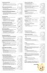
Broadband Cable Networks
User Manual
HDP230
59300192
Rev.002
January 16, 2006
1(17)
HDO Series
User Manual
Teleste Corporation
HDP230
Power Supply
Broadband Cable Networks
User Manual
HDP230
59300192
Rev.002
January 16, 2006
2(17)
Introduction
The HDP230 is a switched mode power supply unit for the HDO optical
headend platform and can be installed in HDX002 installation frame.
The power supply module includes protection against output short circuit, over
voltage and overheating of the electronic circuits. Other standard features
include passive power factor correction (PFC), field replaceable fan units and
remote control of all adjustments.
VERSION INFORMATION this document is based on:
Embedded software version
1.6
Hardware version
A
Viewer version
1.3.0
Viewer file
HDP230.DLL
NOTICE
This product complies with the relevant clauses of the European
Directive 2002/96/EC on Waste Electrical and Electronic Equipment
(WEEE). The unit must be recycled or discarded according to
applicable local and national regulations.
Broadband Cable Networks
User Manual
HDP230
59300192
Rev.002
January 16, 2006
3(17)
Parts and functions
Front and rear panel
7905078
1
6
2
7
4
3
5
Figure 1. HDP230 Power Supply Module.
8
Broadband Cable Networks
User Manual
HDP230
59300192
Rev.002
January 16, 2006
4(17)
1 & 4) Cooling fans
Fan units draw air into the module through the front panel vent. Airflow is then
directed through the module and expelled from the rear panel vent.
Caution! Do not block the fan vents. Doing so may cause heat to build up
inside the module and result interruption in signal operation. Fan speeds are
automatically controlled based on the internal temperature of the unit. They will
always rotate and run at full speed for a short time after the unit is powered up.
2 & 3) Indicators
The front panel LED indicators display unit status. For more information, see the
‘Indicators’ chapter.
5) Extractor handle
The module extractor handle is a mechanical lever that allows easy extraction
and removal of the module without the need for any additional tools.
6) Module data and power connector
The D-9 connector on the rear of the module connects to the installation frame
and provides HDO bus data link to the unit and also powering to the CPU if AC
input is missing.
7) Power bus connector
The DC terminal block on the rear of the module provides power to other
modules in the HDX002 chassis. Use the power supply connection cable
included in the packing to connect the power bus connector to the chassis.
8) AC power connector
Operating AC input voltages of 195…264 VAC at 47…63 Hz are supported. The
power supply module has no separate power switch. It will continuously supply
power to any HDO application module connected in the system.
Broadband Cable Networks
User Manual
HDP230
59300192
Rev.002
January 16, 2006
5(17)
Installation
Installing the module
The module should be positioned in slot 1, 2, 11 or 12 (right- or leftmost slots) to
make sure that power connection reaches rack's power connector. With the
module extractor handle in its right-hand stop position (eject position) slide the
module along the guide rails into a slot, pushing it in until the extractor handle
rest on the latch rail extrusion of the HDX002 chassis. The module’s D-9
connector should now be partially mated with the back plane connector.
Move the extractor handle on the front panel to the closed position by pressing
the extractor handle inwards towards the front panel until the module is fully
seated in the chassis and the extractor handle locks into place.
After the module is installed make the necessary power bus connection and
connect the unit with a power cord to the mains voltage.
Building a power backup
Multiple HDP230 power supplies can be connected in parallel to implement a
power backup function. The power backup can be built inside one installation
frame or between installation frames. When connected in parallel the power
supplies work in an automatic load sharing mode (N+1 backup mode). HDX105
power backup cable is used when installation frames are connected in parallel
to implement the power backup function between installation frames. HDX105
cable has connectors for five installation frames.
Power backup - Restrictions and recommendations
−
−
−
−
Maximum number of power supplies connected in parallel is six.
Maximum number of installation frames connected in parallel is five.
Maximum number of power supplies in one installation frame is two.
When the power supply is placed into module slot 1 or 12 it is recommended
to use the outermost power connector at the rear panel of the installation
frame to ensure some free power cable between the frame and the module.
This enables uninterrupted operation during the replacement of the fan unit.
Broadband Cable Networks
User Manual
HDP230
59300192
Rev.002
January 16, 2006
6(17)
Removing the module
Disconnect the power bus connection and the AC power connection. Move the
extractor handle on the front panel to the eject position. Remove the module by
carefully pulling it out of its slot (Figure 2).
7905144
2
1
Figure 2. Removal of the module.
Broadband Cable Networks
User Manual
HDP230
59300192
Rev.002
January 16, 2006
7(17)
Replacing the fan units
Design of the fan units allows them to be removed and replaced while the
power is on and without interrupting the operation. The module itself cannot be
monitored during the replacement of the fan units.
Keep the AC power cable and the power bus cable connected and carefully pull
the module from the chassis as much as the power bus cable allows. Working
through the apertures on the sides of the fan unit use a thin-bladed screwdriver
and carefully prise free the fan unit from its location (Figure 3). Disconnect the
wiring connector from the PCB and remove the fan unit.
Installation is the reverse of removal. After installation, make sure that the fan
operates correctly and there are no fan-related alarms visible in the user
interface.
7905136
2
1
2
1
Figure 3. Removal of the fan unit.
Broadband Cable Networks
User Manual
HDP230
59300192
Rev.002
January 16, 2006
8(17)
Indicators
The unit has two LEDs on the front panel labelled as SIGNAL (S) and MODULE
(M). These LEDs’ colours reflect the unit’s alarm status, i.e. what alarms are
active. Power related alarms are indicated with Signal LED, others with Module
LED.
If there are one or more “Major” alarms, the affected LED will be red. If there are
no “Major” alarms, but one or more “Minor” alarms, the affected LED will be
yellow. If there are no “Major” or “Minor” alarms, the LED will be green. Note
that the “Notification” alarms do not affect LEDs.
During the power-up sequence both LEDs are yellow and fans run at full speed.
Module LED blinks when configuration session (viewer) is open to the module.
Both LEDs blink simultaneously in red if application software cannot start.
See the ‘Alarms / flags’ chapter for details on alarms and LED usage.
Broadband Cable Networks
User Manual
HDP230
59300192
Rev.002
January 16, 2006
9(17)
Software
Establishing connection
All the needed configurations and adjustments can be carried out locally or
remotely by using the CATVisor Commander software. A connection to HDP230
is possible using the following two methods:
-
IP connection through HDC100’s Ethernet port.
-
A DVX021 connection cable is connected between a COM port of a PC and
the management bus connector of the HDX002 installation frame. Note! If
there is a HDC100 (or other HDO bus master) connected to the bus, it
cannot communicate with the HDO devices while Commander is connected
to the bus. This also means that the EMS system cannot access HDO
devices either. Therefore IP connection is recommended in systems
equipped with HDC100.
More detailed hardware requirements and software installation instructions can
be found from the Commander User Manual supplied with the software.
Broadband Cable Networks
User Manual
HDP230
59300192
Rev.002
January 16, 2006
10(17)
Alarms / Flags
All module alarms (flags) displayed in CATVisor Commander and EMS with
affected LED and factory default severity settings are described in the table
below.
Alarm severities (Major / Minor / Notification / Disabled) and alarm limits can be
configured by the user. See the ‘Monitoring’ chapter for more details.
Alarm text
Internal error
Fan failure
Settings changed
Application started
AC input voltage
missing
Temperature high
Temperature low
+6.3 V output
voltage high
+6.3 V output
voltage low
+25 V output
voltage high
+25 V output
voltage low
+6.3 V output
current high
+6.3 V output
current low
+25 V output
current high
+25 V output
current low
Total output power
high
Total output power
low
Description & suggested corrective action
Internal error in unit prevents normal operation. If resetting
the unit doesn’t help, contact Teleste support.
Cooling fan is not operating correctly. Check fan rotation and
cabling. Replace fan if necessary.
Unit's settings have been modified by user during last
minute.
Unit was reset or rebooted during last minute.
Input AC voltage is missing. Check cable connection.
Unit internal temperature is above high limit. Check ambient
(fan intake) temperature and adjust if necessary.
Unit internal temperature is below low limit. Check ambient
(fan intake) temperature and adjust if necessary.
+6.3 V output voltage is above high limit. Check voltage and
contact Teleste support if necessary.
+6.3 V output voltage is below low limit. Check voltage and
contact Teleste support if necessary.
+25 V output voltage is above high limit. Check voltage and
contact Teleste support if necessary.
+25 V output voltage is below low limit. Check voltage and
contact Teleste support if necessary.
+6.3 V output current is above high limit. Check current and
add / redistribute power supplies if necessary.
+6.3 V output current is below low limit. Check current and
redistribute power supplies if necessary.
+25 V output current is above high limit. Check current and
add / redistribute power supplies if necessary.
+25 V output current is below low limit. Check current and
redistribute power supplies if necessary.
Total output power is above high limit. Check output currents
and add / redistribute power supplies if necessary.
Total output power is below low limit. Check output currents
and redistribute power supplies if necessary.
LED
Factory default
severity
M
Major
M
Major
M
Notification
M
Notification
S
Major
M
Major & Minor
M
Major
S
Major
S
Major
S
Major
S
Major
S
Major
S
Disabled
S
Major
S
Disabled
S
Major
S
Disabled
Broadband Cable Networks
User Manual
HDP230
59300192
Rev.002
January 16, 2006
11(17)
Viewer Pages
Status
The "Status" page shows module present status and possible alarms (="flags").
Figure 4. The Status page
Each alarm is coded according to its severity:
-
Red for Major (“Alarm”)
-
Yellow for Minor (“Warning”)
-
Blue for Notification
Alarm severities can be configured on the “Monitoring” page. For additional
information about status flags, see table of module flag descriptions in the
‘Alarms / flags’ chapter.
It is possible to hide the less critical flags by checking the corresponding check
box for warnings and/or notifications. Note! Regardless of the selection
warnings are always sent to the EMS system.
Broadband Cable Networks
User Manual
HDP230
59300192
Rev.002
January 16, 2006
12(17)
Measurements
The "Measurements" page displays all HDP230 powering measurements.
Figure 5. The Measurements page
Current values
The “AC input voltage” field displays either “Missing” or “OK” indicating the
current status of AC input. When AC input voltage is missing, the CPU is
powered from another PSU through rack D-9 connector.
The “Total power” field displays the total output power sum of both voltages.
The “+6.3 V” and “+25 V” fields show the operating voltage and current values.
The “Temperature” field shows internal temperature of the unit.
The background colour of the fields change to indicate alarms. A green
background means legal values; red is the symbol for a major alarm and yellow
for a minor alarm.
Minimum & maximum values
The “Minimum & Maximum values” frame allows user to view history data such
as maximum and minimum values of voltages, currents and temperature.
The “Time since min & max reset” field shows the time since the history values
were reset, or the unit was powered up. The format is days, hours, minutes and
seconds. The “Reset min & max” button clears measurement history.
Broadband Cable Networks
User Manual
HDP230
59300192
Rev.002
January 16, 2006
13(17)
Monitoring
The "Monitoring" page displays monitored parameters and their values as well
as alarm limits, statuses and severity settings.
Figure 6. The Monitoring page
Analog parameters
Each monitored analog parameter of the unit is displayed in the upper half of
the frame with following information in the list:
Analog parameter: Name of the monitored parameter.
Alarm: Alarm status of the parameter: No / Lo / Hi / LOLO / HIHI
Value: Current measured value.
HIHI: High major alarm limit
HI: High minor alarm limit.
LO: Low minor alarm limit
LOLO: Low major alarm limit.
Deadband: Specifies how much the measured value has to be on the "safe"
side of alarm limit before turning off the alarm.
Unit: Unit of the measured parameter.
The colour of each list entry and the icon next to parameter name indicates
alarm status:
-
green for legal value
-
red for major alarm
-
yellow for minor alarm
-
grey for disabled alarm
Broadband Cable Networks
User Manual
HDP230
59300192
Rev.002
January 16, 2006
14(17)
The alarm settings are user configurable by double-clicking an analog
parameter. This will open a dialog box with parameter's alarm limits and
deadband that can be edited by users with at least "Service" level user rights.
For others this is read-only information.
Figure 7. The analog alarm configuration dialog box
Each alarm limit can be individually enabled/disabled and configured. The alarm
limits should be in decreasing order, preferably with more than "Deadband"
units between each limit.
Discrete parameters
Each monitored discrete parameter of the unit is displayed in the lower half of
the frame with following information in the list:
Discrete parameter: Name of the monitored parameter.
Alarm: Alarm status of the parameter: No / Notification / Minor / Major. If the
alarm is disabled, but parameter is in alarming state, "Yes" is shown.
Setting: Alarm severity can be configured to Major, Minor, Notification or
Disabled.
The colour of each list entry and the icon next to parameter name indicates
alarm status:
-
green for legal value
-
red for major alarm
-
yellow for minor alarm
-
blue for notification
-
grey for disabled alarm
Broadband Cable Networks
User Manual
HDP230
59300192
Rev.002
January 16, 2006
15(17)
The alarm severity setting is user configurable by double-clicking a discrete
parameter. This will open a dialog box, which can be edited by users with at
least "Service" level user rights. For others this is read-only information.
Figure 8. The discrete alarm configuration dialog box
Alarm control
Alarm control frame provides independent on-delay and off-delay timers. The
time delay feature can be used to eliminate false alarm triggering due to
momentary disturbances. An alarm is only active when “Detection” is enabled
and the monitored parameter has been over limit longer than "Delay On" time.
Alarm goes off when the parameter has been inside limits longer than "Delay
Off" time.
The settings on the “Alarm control” frame can be edited by a user with at least
Service level user rights. For others this is read-only information. It is
recommended not to change these values without fully understanding the
effects on EMS system performance.
Broadband Cable Networks
User Manual
HDP230
59300192
Rev.002
January 16, 2006
16(17)
Alarm log
Clicking the "Alarm log" button opens alarm history dialog box.
Figure 9. The Alarm log page
The “Alarm log” dialog box displays the alarm history for latest 32 events. The
list is stored in non-volatile memory. All entries are date and time stamped with
the most current entry at the bottom. Note that date/time information may not be
correct for events that occurred before latest reset.
The colour of each list entry and the icon next to parameter name indicates
alarm status:
-
green for legal value
-
red for a major alarm
-
yellow for a minor alarm
-
blue for a notification
Total number of entries in the alarm log list is shown in the “Number of entries”
field. The index number of the last entry is displayed in the accompanying field.
Total number of entries are limited to 32. The oldest entry is overwritten when
the log becomes full.
To update “Alarm log” page, click the “Refresh” button.
“Clear and regenerate log” button empties the alarm log and restarts alarm
detection.
Broadband Cable Networks
User Manual
HDP230
59300192
Rev.002
January 16, 2006
17(17)
Properties
Figure 10. The Properties page
Identification
The user can enter a descriptive alias name for the station into the “Name” field,
such as site location etc. Alias name can contain up to 63 alphanumeric
characters.
The type, configuration, serial number and hardware version of the module as
well as the software information are read-only information.
Statistics
Each HDO device has its “Rack” and “Slot” number displayed in the “Position”
field.
The “Uptime” field shows the time since the last reset / power up. The format is
days, hours, minutes and seconds.
The "Total uptime" field shows the total number of full operating days of the unit.
The "Reset count" field shows the total number of unit resets.
Copy to clipboard
“Copy to clipboard” button copies all information on the “Properties” page onto
the clipboard. This can then e.g. be pasted to an email message when
contacting Teleste support.