1
User Manual
For quick installation information please refer to the iConnect
Quick Start Installation Guide provided on our website: www.electronics-line.com
Quick Reference Guide
Function
Press…
Additional Information
ARM
OR
FULL
INSTANT
ARM
DISARM
If One-Key Arming is disabled
on the Control System, enter
your user code when arming.
OR
PART
PERIMETER
Hold down this key until
“Instant Arming OK?” is
displayed. Then Press √.
[USER CODE]
The default Master code is
1234.
Instant arming cancels the
entry delay after Part or
Perimeter arming. This
feature can be enabled by
your installer.
Entering your user code also
silences the siren in the event
of an alarm.
PANIC
ALARM
+
FIRE
ALARM
+
MEDICAL
ALARM
+
MENU MODE
then [USER CODE]
Use the menu navigation keys
(/) until the required
menu item is displayed then
press √. Alternatively, enter
the shortcut (e.g. 21 for
Bypass Zones).
CHECK
TROUBLE
CONDITIONS
Use this key scroll the
system trouble list
Pressing also silences any
trouble tones that may be
sounded by the system.
SWITCH
HA/PGM
UNIT ON
then [HA/PGM UNIT #]
SWITCH
HA/PGM
UNIT OFF
then [HA/PGM UNIT #]
Press these keys together and
hold them down to generate
an alarm.
Enter the HA module number
in two digits
(e.g. 03, or 30/31 for PGM).
Hold down this key until
“Service Call Dialing” is
displayed. The number dialed
for the service call is
programmed by your
installer.
SERVICE
CALL
GLOBAL
CHIME
then
Use the menu navigation
keys (/) to choose enable
or disable, then press √.
RECORD
MESSAGE
then
After recording a message,
“Message Waiting” is
displayed until the message
is played back.
Function
PLAY
MESSAGE
Press…
Additional Information
then
The Message Center is an
optional feature that is
included with certain versions
of iConnect
Control
System.
Telecontrol Commands
Function
*
Press…
Function
2-WAY AUDIO
DISARM
FULL ARM
SIREN
CANCEL
HA/PGM
UNIT XX ON*
then
HA/PGM
UNIT XX OFF*
then
Press…
EXTEND CALL
DISCONNECT
for PGM XX=30/31
-3-
then
Table of Contents
Quick Reference Guide ..................................................................................................................... 2
Table of Contents .............................................................................................................................. 4
1.
Introduction and Overview ...................................................................................................... 6
1.1.
Documentation Conventions .............................................................................................. 6
1.2.
Security System Components ............................................................................................ 7
1.3.
System Monitoring ............................................................................................................. 8
1.4.
Home Automation .............................................................................................................. 8
1.5.
Self-Monitoring ................................................................................................................... 8
1.6.
Telephone Control .............................................................................................................. 8
1.7.
Vocal Message Annunciation ............................................................................................. 9
1.8.
Web/Smartphone Access................................................................................................... 9
2.
The User Interface .................................................................................................................. 10
2.1.
Front Panel ...................................................................................................................... 10
2.2.
Alarm Sounding Patterns ................................................................................................. 12
2.3.
Keyfobs ............................................................................................................................ 12
2.4.
Wireless Keypads ............................................................................................................ 12
3.
Arming and Disarming ........................................................................................................... 15
3.1.
Arming Modes .................................................................................................................. 15
3.2.
Arming the System ........................................................................................................... 15
3.3.
Disarming the System ...................................................................................................... 17
3.4.
Arm Status Indication and Other System Status Indication .............................................. 17
3.5.
Arming and System Tones ............................................................................................... 18
3.6.
Remote Arming and Disarming ........................................................................................ 19
4.
Web User Application ............................................................................................................ 21
4.1.
Register to MyELAS ......................................................................................................... 21
4.2.
Login to MyELAS ............................................................................................................. 22
4.3.
The Main Page ................................................................................................................. 23
4.4.
Arming and Disarming...................................................................................................... 26
4.5.
Web Application Settings ................................................................................................. 27
4.6.
Event Log History ............................................................................................................. 36
4.7.
Home Automation ............................................................................................................ 37
4.8.
Video Verification ............................................................................................................. 38
5.
Panic Alarms .......................................................................................................................... 41
5.1.
Keypad Alarms ................................................................................................................. 41
5.2.
Keyfob Panic Alarm.......................................................................................................... 41
5.3.
Medical/Panic Alarm ........................................................................................................ 41
6.
Home Automation and PGM .................................................................................................. 42
6.1.
Keypad Control ................................................................................................................ 42
6.2.
Keyfob Control ................................................................................................................. 43
6.3.
Telephone Control ............................................................................................................ 43
6.4.
SMS Control ..................................................................................................................... 43
6.5.
Scheduling (not relevant to PGM)..................................................................................... 44
7.
Telecontrol .............................................................................................................................. 45
7.1.
Calling your Home............................................................................................................ 45
7.2.
Service Call ...................................................................................................................... 47
7.3.
Two-Way Audio after an Alarm ........................................................................................ 47
7.4.
Two-Way Audio Follow-Me............................................................................................... 47
-4-
7.5.
8.
Simplex Mode .................................................................................................................. 47
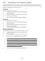
Advanced System Operation ................................................................................................. 48
8.1.
Cancel Report .................................................................................................................. 49
8.2.
Zone Bypassing/Unbypassing .......................................................................................... 49
8.3.
User Codes ...................................................................................................................... 50
8.4.
Follow-Me ........................................................................................................................ 52
8.5.
Event Log ......................................................................................................................... 52
8.6.
Service Menu ................................................................................................................... 53
Appendix A: Menu Structure ........................................................................................................... 59
Appendix B: Glossary...................................................................................................................... 60
-5-
1.
Introduction and Overview
This user manual explains all you need to know about your iConnect security system
and provides step-by-step instructions for all the system’s user functions. In addition to
the explanation you will receive from your installer, we urge you to read this manual so
that you can take full advantage of your system’s features. Keep this manual in an
accessible location for future reference.
system has many features in order to suit a wide range of applications.
The iConnect
This manual outlines all of these features but it is likely that there are options that are
not relevant to your system. If you have any questions regarding the availability of the
features described in the manual, please ask your installer.
1.1.
Documentation Conventions
In order to simplify the procedures that appear in the rest of this manual, the following
conventions are used:
Item…
Description…
Select…
Use the arrow buttons to scroll through the options and
press √.
From the Event
Log Menu, select
Clear Log.
Enter the main menu by pressing √ and entering your
user code. Using the arrow buttons, navigate until you
reach Event Log and press √. Using the arrow buttons,
navigate until you reach Clear Log and press √.
From the Service
menu, select Set
Time/Date, Set
Date.
The same as above only this time you are navigating
through three menu levels.
[7012]
The shortcut to a specific menu item from the main menu.
In this case, this is the shortcut for Set Date. These
appear in the procedures as an additional aid to menu
navigation.
[#5]
A shortcut to a specific item in a sub-menu. For example,
[#5] is the shortcut to Bell enable disable in the submenu that is opened once you have selected the detector
you want to program.
√ , buttons
Indicate buttons that appear on the keypad (
5. Interface Test
,
)
The text that actually appears on the LCD display (italics).
Note
Important caution, please pay attention.
-6-
1.2.
Security System Components
Your security system is made up of a Control System, various detectors and a number of
optional peripheral devices. This section explains the role of each component in your
system.
Control System
The Control System is the brain of the system. It
communicates with all the devices connected to the
system. For example, in the event of a burglary, a
detector sends a signal to the Control System
indicating that it has sensed motion on the premises.
On receiving this signal, the Control System makes
the decision to report the alarm to your monitoring
service and activate the siren.
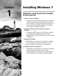
Detectors
Detectors are the devices that protect your home, alerting the
Control System when there is a breach in security. Magnetic
contacts protect your doors and windows while motion detectors
with built-in image capture modules are able to detect an intruder
moving across its field of view and snap an instant image as proof
of intrusion. Additionally, smoke, carbon monoxide, gas leak and
flood detectors can be installed to provide an early warning in the
event of a fire, the presence of dangerous gases or the potential for
flooding.
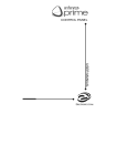
Keyfobs
Keyfobs are hand-held transmitters that are used to operate the
system. Various keyfobs are available providing a number of
functions. For example, arming/disarming the system, sending
medical and panic alarms and various home automation functions.
Keypads
The keypads enable you to communicate with the Control System
in order to perform a number of different functions. The main
function you can perform using a keypad is to arm the system
when leaving your home and to disarm on your return.
Sirens and Strobes
While the Control System includes a built-in internal siren, it is
possible that you also have an external siren and strobes installed.
The sirens are sounded and the strobes are activated during certain
alarm conditions serving to warn you and ward off intruders.
-7-
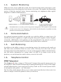
1.3.
System Monitoring
When an event occurs within the system, the Control System sends a message to your
monitoring service describing the exact nature of the event. This enables the monitoring
service to take the required action. System monitoring can implement either regular
telephone or cellular communication.
A detector detects. The Control System is alerted.
An alarm is generated and the
monitoring service is notified.
Remember that no security system can prevent emergencies. This system is only intended
to alert you in case of an emergency and should not take the place of prudent security
practices or life and property insurance.
1.4.
Home Automation
An optional expansion module can provide you with the ability to control up to 16
individual electrical appliances or lights using the front panel keypad, wireless keypads
or keyfobs. Additionally, each appliance can be programmed to be turned on and off
automatically according to various schedules and system status conditions.
1.5.
Self-Monitoring
In addition to the ability to report to a monitoring service, the system can also send you
and other users notification when an event occurs. This may be in the form of vocal
messages played over the telephone or, if your system supports cellular communication,
you can receive information on system status via SMS. If an alarm occurs on the
premises, you are informed no matter where you are in the world.
1.6.
Telephone Control
DTMF Telecontrol
The iConnect
offers a range of “Telecontrol” features that provide remote access via
the telephone. These features include remote arming/disarming, HA on/off, PGM output
activation/deactivation, siren cancel and Two-Way audio via the Control System’s builtin microphone and speaker -- see Telecontrol.
The Two-Way Audio features allow you to contact your home directly in the event of an
alarm or simply to check the premises when you are away.
-8-
SMS Control
Using your cellular phone, you can also send commands to the appliances controlled by
the Home Automation feature using SMS and receive confirmation when the command
is received.
1.7.
Vocal Message Annunciation
Vocal message annunciation is an optional feature that, if enabled in programming,
causes the system to play short messages that indicate system status.
1.8.
Web/Smartphone Access
The Web/Smartphone application provides an interface to your security system from
your Internet browser or Smartphone. You can perform a wide range of tasks such as
arm/disarm, zone bypass, user code management and home automation control.
Additionally, you can set up the contacts for whom you wish to be alerted (by email or
text message) when selected events occur.
The Web/Smartphone application also allows you to check your home at any time either
by viewing the history of recent events that have occurred or by viewing video
snapshots from PIR cameras installed on the premises. For further information, see Web
User Application
-9-
2.
The User Interface
There are several methods you can use to operate the system. Apart from the keypad on
the front panel, your system may include a number of peripheral devices such as
keypads and keyfobs.
This chapter provides a brief introduction to each of the devices you can use to operate
the system. It is important that you familiarize yourself with these devices before
reading the following chapters that shall describe system operation in further detail.
The front panel is the main user interface that provides you with all the functions you
Control System is available with the
need to control your security system. iConnect
LCD front panel configuration.
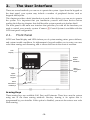
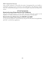
2.1.
Front Panel
LCD Front Panel display and LEDs inform you of system arming status, power failures,
and system trouble conditions. Its alphanumeric keypad enables you to enter your user
code when arming and disarming, and to silence the siren in the event of an alarm.
LCD
Display
System
Status
indicators
Arming
Keys
Menu
Navigation
Keys
Alphanumeric
Keypad
Home
Automation/
PGM Keys
Arming Keys
Three arming keys are available: Full, Part, and Perimeter. These keys arm the system
using one of the three arming methods. One-key Arming is an option that is
programmed by your installer. If this option is disabled, you must also enter a user code
when arming.
-10-
Service Call Button
The Service Call button enables you to contact the monitoring service and talk to an
operator.
To initiate a service call, press
seconds.
and hold down the Service Call key
for a few
Vocal Message Recording and Playback
LCD front panel allows you to record a short message that may be played back later by
another user -- see Service Menu, Message Center.
PGM and Home Automation On/Off Keys
Pressing one of the Home Automation keys (
ON,
OFF) followed by the unit
number (01-16, or 30, 31 for PGM) enables you to control lights and appliances in your
home, activate and deactivate the PGM output.
Pressing both Home Automation keys simultaneously generates an SOS panic alarm.
System Status LEDs
The System Status indicators provide essential information on the status of the system
such as arm, disarm, alarm and power failure conditions.
If the
OK LED is…
It means…
Off
Both AC and Battery power are disconnected.
On – Green
System Power status is OK and there is no System Trouble.
Flashing Green
Open Zone. Check that the windows and doors are closed
and no movement is detected by the detectors within the
protected area).
On – Yellow
System Trouble.
Flashing Yellow (slow)
Battery low from the Control System or transmitters.
Flashing Yellow (fast)
AC loss.
Intermittent On/Off – Yellow
System Trouble in addition to AC loss/Low Battery.
If the Arm Status LED
is…
It means…
Off
The system is disarmed.
On – Green
The system is armed.
Flashing Red
An alarm has occurred. Alarm indication is cleared the
next time you arm the system or view the relevant event
in the event log.
Alarm indication is not displayed after a silent panic alarm.
-11-
System Trouble Indication
In the event that the system detects a trouble condition, “System Trouble” appears on
the display. To identify the problem, scroll through the trouble list by pressing.
Scrolling the trouble list also silences system trouble tones that may be sounded if
enabled in programming. When the trouble condition is restored, it is removed from the
system trouble list. For detailed information on system messages, see Arm Status
Indication.
2.2.
Alarm Sounding Patterns
The following table summarizes various alarms sounded by the control system.
Alarm
Alarm Sounding Pattern Description
Burglary
ON (continuously)
Fire
ON - ON - ON, 1.5-second pause, ON - ON – ON......
Gas
ON - ON - ON - ON (short bursts), 5 second pause, ON - ON - ON ON......
Medical
ON (continuously) – only applicable for Medical alarm from zone
Flood
4 rapid tones sounded once per minute (same as Trouble tones)
Environmental
4 rapid tones sounded once per minute (same as Trouble tones)
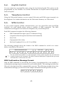
2.3.
Keyfobs
The iConnect
supports two types of keyfob transmitter (EL-4714, EL-4711M/P). The
functions of the buttons on each keyfob are shown below.
Full Arm
Disarm
Perimeter Arm
or Home
Automation/PGM
EL-4714
2.4.
Medical/Panic
Emergency
Part Arm
or Home
Automation/PGM
EL-4711M/P
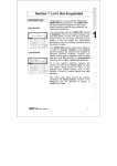
Wireless Keypads
The system supports up to four Wireless Keypads. The Wireless Keypad (EL-4727) is an
intelligent two-way wireless keypad with LCD display. Apart from serving as an
additional arming station, the Wireless Keypad provides memo recording options,
control over up to 16 home automation devices, and panic alarm function. You can arm
and disarm the system using the Smartkey (if supported).
-12-
Speaker
LCD Display
Arming Keys
Keypad
Microphone (optional)
System Status LEDs
Wireless Keypad (EL-4727)
Numeric Keypad
The numeric keypad allows you to arm or disarm the system by entering a user code.
Arming Keys
Three arming keys (Full, Part and Perimeter) allow you to arm the system using one of
the three arming methods – see Arming and Disarming. One-key Arming is an option
that is programmed by your installer. If this option is disabled, you must also enter a
user code when arming.
Panic Alarm
Simultaneously pressing the Full and Perimeter buttons generates a panic alarm.
PGM/Home Automation On/Off Keys
Pressing one of the Home Automation keys followed by the unit number (01-16) enables
you to control lights and appliances in your home.
To generate a panic alarm, press both Home Automation keys simultaneously and hold
them down
Cancel
The Cancel key clears the keypad in the event that you pressed a key by mistake.
For example, when entering your code you enter a wrong digit; the system waits for you
to enter all four digits before it decides that the code is incorrect. Pressing the Cancel key
causes the keypad to disregard what was previously entered enabling you to start again.
-13-
LEDs
Two status LEDs (OK and
If the
OK LED is…
) indicate arming and power status of the system:
It means…
Off
The system is disconnected from all power sources.
On - Green
The keypad is powered by AC and the battery is not low.
Flashing Yellow (slow)
Local backup battery low.
Flashing Yellow (fast)
Wireless Keypad AC loss.
If the
LED is…
It means…
Off
The system is disarmed.
On - Green
The system is armed.
Flashing Red
An alarm has occurred. This alarm indication is reset when
the system is armed using any of the three arming
methods.
Alarm indication is not displayed after a silent panic alarm.
-14-
3.
Arming and Disarming
Arming can be defined as activating the system. When the system is armed, it monitors
the zones that are protected by the detectors. If a detector detects an intrusion, the
system generates an alarm.
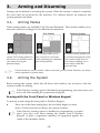
3.1.
Arming Modes
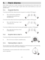
Three arming modes are available: Full, Part and Perimeter. These modes enable you to
arm your system accordingly to suit different circumstances.
Full Arming
Part Arming
Perimeter Arming
Full arming activates the entire
system. This arming method is
used when you intend to leave
your home, leaving the
premises empty.
Part arming enables you to
arm a section of your home
while remaining on a different
part of the premises.
Perimeter arming enables you
to activate the perimeter zones
(the windows and doors of
your home) enabling you to
move freely within the
protected area.
Certain detectors, such as smoke, carbon monoxide, gas and flood detectors, are always
active regardless of system status.
3.2.
Arming the System
Before arming the system, check that all doors and windows are secured so that the
system is ready for arming.
If the One-key Arming option is disabled in programming, you must enter your
user code when arming the system from a keypad.
Arming with the Front Panel or Wireless Keypad
To arm the system using the front panel or Wireless Keypad:
Press one of the three arming keys; the exit delay begins to count
down. At the end of the exit delay, the system is armed.
If the One-key Arming option is disabled in programming, you must
enter your user code when arming the system from a Wireless
Keypad, or place a registered smartkey (if supported) against the
center of the smartkey reader.
-15-
Arming with the Keyfob
To arm the system using the keyfob:
Press the relevant button on your keyfob (see Keyfobs); the exit delay
begins to count down. At the end of the exit delay, the system
is armed.
Arming with the Key Switch
To arm the system using a key switch:
Open/close the key switch accordingly.
Forced Arming
Forced arming enables you to arm when the system is not ready. For example, if a door
protected by a magnetic contact is open, you may arm the system on condition that the
door will be closed by the end of the Exit delay. If the door is still open after the exit
delay expires, an alarm is generated.
Forced arming is available only if the option is enabled in programming. Forced arming
may be enabled for specific zones or for the entire system.
Instant Arming
Instant arming is a feature that allows you to cancel the entry delay after Part or
Perimeter arming the system. For this feature to function, it must be enabled in
programming by your installer.
To instantly arm the system.
1.
Check if the system is ready to arm.
2.
Press the Part or Perimeter arming key on the keypad and enter your user
code if One-Key Arming is disabled.
3.
Press and hold down on your keypad until the message Instant Arming,
OK? is displayed
4.
Press √; the entry delay for the current arming period is canceled.
Supervised Arm
Supervised Arm is an optional feature designed to supervise intrusion detector activity
before you arm the system.
If supervised arm is enabled in programming and the system has not received a
transmission from a detector for a certain amount of time, all arming methods that
include that detector shall not be available.
In this case, press to check which detector is causing the “System Not Ready”
condition.
To make the required arming method available, activate the detector. If activating the
detector does not help, there may be a problem with the detector. You can bypass the
faulty detector’s zone to allow system arming until the problem is remedied – see Zone
Bypassing/Unbypassing.
-16-
3.3.
Disarming the System
When you enter the premises, the entry delay begins to count down. You must disarm
the system within the entry delay time to prevent the system from triggering an alarm.
To disarm the system using a keypad:
Enter your user code.
To disarm the system using a keyfob:
Press the disarm button – see Keyfobs
To disarm the system using a key switch:
Open/close the key switch accordingly.
To disarm the System using a Smartkey (if supported):
Place a registered smartkey against the
center of the smartkey reader of the
Wireless Keypad. When the smartkey is read, the keypad will sound a
beep – the system is disarmed.
3.4.
Arm Status Indication and Other System
Status Indication
The system’s arm status is displayed on the front
panel only. The following table explains the
various arm status descriptions that appear on
the LCD display.
Status
Means…
DISARMED
The system is disarmed.
DISARMED
12:22:12
FULL ARMED
PART ARMED
The system has been armed using the displayed arming method.
PERIMETER ARMED
FULL ARMING
PART ARMING
The system is in the process of arming (displayed during exit
delay).
PERIMETER ARMING
PART ARMED INST
PERIM ARMED INST
PART ARMING INST
PERI ARMING INST
The system has been armed using the displayed arming method
with the Instant arm feature activated.
The system is in the process of arming with the Instant arm
feature activated.
The system may be programmed to display arm status at all times or only for the first
two minutes or 30 seconds after you arm or disarm the system according to the system's
configuration as programmed by the installer.
-17-
In addition to arm status, the system displays further status messages on the front
panel’s display. The following table explains common status indication messages that
may prevent you from arming your system.
Status
Means…
ZONES IN ALARM
Zones have been violated.
TAMPER ALARM
The system has been tampered with.
SYSTEM NOT READY
The system is not ready to arm, check that all doors and windows
are closed.
KEYPAD LOCKED
Five unsuccessful attempts were made to enter a user code; the
keypad is locked for 30 minutes. If this message appears, it is still
possible to arm/disarm the system using a keyfob. Arming is
possible using a keypad if one key arming is enabled.
SYSTEM TROUBLE
A trouble condition has been detected, press for further details.
3.5.
Arming and System Tones
System tones are the chimes that the system
sounds to indicate entry/exit delay, arming and
disarming, system troubles and so on. Various
options are available that determine the pattern
of these tones.
FULL ARMING
7 TO EXIT
System tones may be sounded by either the external wireless siren or the Control
System’s built-in siren.
The following table is a summary of the tones sounded by the control system.
Status
Tones
Description
Exit Delay/
Entry Delay
4 tones or continuous tones.
The exit/entry delay is counting down.
The tones quicken when
there are 13 seconds
remaining and quicken again
when there are 5 seconds
remaining.
The number of tones sounded during
each delay is programmed by your
installer.
Chime
2-tone sequence (similar to a
doorbell – high to low).
A detector that has been programmed
to chime by your installer has been
activated – see Service Menu, Global
Chime.
Arm
3-tone sequence (low to
high) sounded twice
The system has been armed using
any of the arming methods. Arm
tones are optional and are
programmed by the installer.
Disarm
3-tone sequence (high to
low).
The system has been disarmed.
Disarm tones are optional and are
programmed by the installer.
Home
Automation
Rapid 2-tone sequence
An automated device has been turned
On or Off using a wireless keypad or
keyfob. This audible indication is
programmed by your installer.
-18-
Status
Tones
Description
System
Trouble
4 rapid tones sounded once
per minute.
A trouble condition has been
detected, press for further details.
For Fire Trouble Tones, there is a
programmable option to repeat the
tones every 3½ hours until the
problem has been taken care of.
Note: System trouble tones
are not sounded from
10:00pm to 7:00am
3.6.
Remote Arming and Disarming
Remote Arming/Disarming via SMS
You can arm and disarm the system remotely by sending the SMS commands from a
cellular phone to the cellular communications module.
Each SMS command contains the following elements:
SMS Command Descriptor (up to 43 characters of free text)
# (separates the descriptor from the actual command)
User Code
Command (120=Disarm, 121=Full Arm, 122=Part Arm, 123=Perimeter
Arm, 124=Full + Perimeter Arm, 125=Part + Perimeter Arm, 200 = Arm
Status)
The following example shows the format of an SMS command for disarming the system:
SMS Command Descriptor
D
I
S
A
R
User Code
M
#
1
2
3
Command
4
1
2
0
While the SMS Command Descriptor is optional, you must start the SMS command with
the # symbol for the system to accept the command.
Arm Status Reply
On receiving an Arm Status request message, the system returns a status message to the
sender. This message includes the system status and the descriptor of the user or the
device used to arm/disarm the system.
The following example shows an Arm Status reply where the system has been fully
armed by a user named Mark.
F
U
L
L
A
R
M
-19-
E
D
-
M
A
R
K
SMS Confirmation Message
After an SMS command is executed by the system, if programmed by your installer, a
confirmation message may be returned to your mobile phone. The following example
shows the confirmation message you receive for the sample command from the previous
section.
D I
S
A R M E
D
Remote Arming/Disarming via the Telephone
Using the Telecontrol feature, you can “Full” arm and disarm the system via the
telephone. For further information on the Telecontrol features, see Telecontrol.
Remote Arming/Disarming via WUAPP and WAP
You can arm and disarm the system remotely using the WUAPP (Web User Application)
and WAP – see Web User Application.
-20-
4.
Web User Application
The Web User Application - MyELAS provides a full interface to your system from a
local or remote PC. Via the Web you can perform a wide range of tasks such as
arm/disarm, zone bypass, user code management and home automation control.
The Smartphone Application - MyELAS provides access to the Web User Application
from your Smartphone (iPhone or Android).
4.1.
Register to MyELAS
The Web Application is part of the service provider’s Web site and requires the end user to
register in order to gain access to the Web site.
To Register to MyELAS:
1.
Go to www.myelas.com. The Login page is displayed.
Figure 1: Login Page
If you have already registered but forgotten your Login details, click the
Password Recovery link and you can request that the password to be sent to
your predefined email address.
2.
Click the Self Registration link. The Self Registration page is displayed
Figure 2: Self Registration Page
-21-
3.
Enter the following registration details into the Self Registration page:
First/Last Name
Enter your First and Last Name
Email (Login Name)
Enter your chosen Login Name (i.e. email address)
Password/Confirm
Enter your chosen Password twice (minimum of 6 characters
and at least one digit)
Panel ID
Enter your Panel ID (supplied by your service provider or
as it appears on the sticker located on the side of the panel)
Location
Select your location time zone
Anti-Spam Code
Enter the displayed anti-spam code into this field
Terms and Conditions
Agreement
Read the Terms and Conditions Agreement and check the
checkbox to continue
4.
Click Register. The Self Registration process sends a confirmation email to your specified
email address.
5.
From the received email, click the attached link to confirm your registration. The Login
page is displayed and you can now login to the Web Application.
4.2.
Login to MyELAS
To enter MyELAS:
1.
Go to www.myelas.com. The Login page is displayed.
Figure 3: Login Page
To login to the Web Application:
2.
3.
Enter your User Name and Password that you supplied during the registration process.
Enter your Pass Code (User Code) and click the Enter/Login button.
For system security reasons, you must change the password immediately at first
login. You can change your password on the Change Password page that is
accessible from the Settings menu. Your new password should be no less than
six characters and must start with a letter.
You can also login to MyELAS using your Smartphone: Download the MyELAS app
from the Apple App Store or Google Play for Android devices.
-22-
When using the Smartphone application service, the Login page may look similar to the
following examples:
Figure 4: Login Page (iPhone)
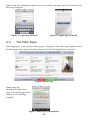
4.3.
Figure 5: Login Page (Android)
The Main Page
After logging in, your system’s home page is displayed. The following diagram shows
the Main page and explains the main elements of the Web application’s interface.
Figure 6: Main Page
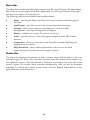
When using the
Smartphone application
service, the main page looks
similar to the following
example:
Figure 7: Main Page (Smartphone)
-23-
Menu Bar
The Menu Bar includes the Main Menu options and the Log Off button. The Main Menu
offers links to various pages in the Web Application. Use the Logoff button on the right
side menu to properly close the session.
The following options are available from the Main Menu:
Home – pressing the Home tab allows the user to return to the Main page at
any time
Arm/Disarm – provides access to the System Operation Area page.
Settings – offers various options including user code and contact
management, event log viewing and zone bypass.
History – enables you to view the system’s event log
Video – provides access to view still capture snapshots from PIR Camera
detectors
Automation – allows you to control and schedule automated lighting and
appliances in your home
Help/Download – offers online explanations on how to use the Web
Application plus FAQ and customer support options.
Status Bar
The Status bar displays information on your system’s status and the name of the user
currently logged in. Above the status bar, the time when the system status display was
last updated is shown. This information is displayed according to the local time at the
control system. The system status refreshes automatically, and can also be refreshed
manually. To refresh the current system status, click the Refresh Status button on the
right-hand side of the Status bar.
-24-
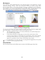
Workspace
The workspace offers additional links to the following pages of the application: System
Operation, Settings, History, Video and Automation. When you choose a page, either
from the Main Menu, or from the workspace, the page is displayed in the workspace.
For example, if you choose Arm/Disarm from the Main Menu, System Operation area
and System Status area are displayed in the workspace (see the example below).
Figure 8: Workspace Example Page
You can arm and disarm the system using the Arm/Disarm drop-down box (upper-right
part of the page) or using the buttons in the System Operation Area.
The Web Application allows you to arm and disarm your system using any of
the available arming methods.
On the Status Bar below on the page you can see the current status of the
system (in our example it is Disarmed and System Ready, which means that the
system and all the detectors are working properly and there are no events to
report). It is possible to check if there were alarms in the system.
It is important to note that when you are using the Web application, the system
is armed with the programmed delay
Home Button
Press the Home button on the Main menu to return to the Main page at any time.
-25-
4.4.
Arming and Disarming
Figure 9: System Operation Area Page
Three arming modes are available: Away, Part and Perimeter. These modes enable you
to arm your system accordingly to suit different circumstances.
Full Arming
Full Arming activates the entire system. This arming method is
used when you intend to leave your home, leaving the premises
empty.
Part Arming
Part Arming enables you to arm a section of your home while
remaining on a different part of the premises. For example, at
night your family is upstairs while the area downstairs is armed.
Perimeter Arming
Perimeter Arming enables you to turn on the perimeter zones
(the windows and doors of your home) enabling you to move
freely within the protected area.
Combination Arming
In addition to the three arming modes, you can activate a combination
of Away and Perimeter or Part and Perimeter arming modes.
Before arming the system, check that all doors and windows are closed so that the
system is ready for arming. System status is displayed on the status bar at the bottom of
the page. If you are arming from a remote location and the system status is "Not Ready",
you may temporarily bypass any zone that is causing this condition.
Disarming can be regarded as turning the security system off. When the system is
disarmed only zones that are defined as active 24 hours are monitored (e.g. Flood, Gas
and Panic zones).
-26-
4.5.
Web Application Settings
The Web Application Settings area offers various options including System/Web user codes,
contact and password management, user interface appearance and descriptors, event log
viewing and zone bypass capabilities.
System Users and Codes
The System Users and Codes page enables you to manage your system's users. The page
displays a table of the system's current users and enables you add, edit and delete users
as required.
This capability is available only to a user with a Master code, the highest level of
authorization.
The System Users and Codes page provides a useful tool for managing your system’s
users. In this area you can add, delete, or change System Users and the User Codes for
your system (for example, add/edit codes for family members).
The following System User types are available:
Master Code
The Master code is the highest user authorization level. With
(Code 1)
the Master code, you can change all other user codes.
Controlled Codes
When you use a controlled user code for arming and
(Codes 2-19)
disarming, the system notifies the monitoring service. You can
assign these codes to your children or employees whose
comings and goings are of interest to you.
Non-controlled
Non-controlled codes do not cause the system to send
Codes (Codes 20-25)
Arm/Disarm reports to the monitoring service. The system
sends a Disarm report only if you use this code to disarm the
system after an alarm occurrence.
Limited Codes
A Limited code is a code that is valid for one day only. This
(Codes 26-27)
code automatically expires 24 hours after it has been
programmed. You can assign a limited code to a visiting guest,
for example.
Duress Code
The Duress code is designed for situations where you are
(Code 28)
being forced to operate the system. This user code performs
the operation selected, while sending a Duress event message
to your monitoring service.
-27-
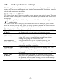
To display the System Users and Codes page:
1. On the Menu Bar, click Settings.
2.
Click System Users and Codes. The System Users and Codes page is displayed.
Figure 10: System Users and Codes Page
To add a new system user:
1. Click Add New User at the bottom of the table; the Add New System User page opens.
2.
3.
4.
5.
6.
7.
Figure 11: Add New System User Page
Enter the user's name in the field provided (16 characters max.).
Choose the user type from the available options.
Enter the new user's 4-digit passcode.
Enter the new user's passcode again for confirmation.
Enter your Master code.
Click Update.
-28-
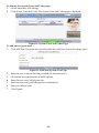
To edit an existing system user:
1. Click Edit for the user you want to modify; the Edit User page opens.
2.
Edit the user's name in the field provided (16 characters max.).
When editing an existing user, you cannot change the user type.
3.
4.
5.
6.
Enter the user's 4-digit passcode.
2.
Click Yes to confirm.
Enter the user's passcode again for confirmation.
Enter your Master code.
Click Update.
To delete a system user:
1. Click Delete for the user you want to remove from the table; the confirmation page opens.
-29-
Web Interface Users and Codes
The Web Interface Users and Codes page enables you to manage your Web's users. The
page displays a table of the system's current users and enables you add, edit and delete
users as required. You can even issue temporary (limited) codes to guests that will
automatically expire after 24 hours.
1. On the Menu Bar, click Settings.
2.
Click Web Interface Users and Codes. The Web Interface Users and Codes page is
displayed.
Figure 12: Web Interface Users and Codes Page
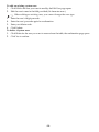
To add a new Web user:
1. Click Add New User at the bottom of the table; the Add New Web User page opens.
2.
3.
4.
5.
6.
7.
8.
Figure 13: Add New Web User Page
Enter the user's name in the field provided (16 characters max.).
Enter the new user's password.
Enter the new user's password again for confirmation.
Enter the Owner User password.
Enter the First Name, Middle Name and Last Name of the new user in the fields
provided.
Enter Phone and Email details of the new user into the fields provided.
Click Add New.
-30-
To edit an existing Web user:
1. Click Edit for the user you want to modify; the Edit User page opens.
2.
3.
4.
5.
6.
7.
8.
Edit the user's name in the field provided (16 characters max.).
Enter the user's password.
Enter the user's password again for confirmation.
Enter the Owner User password.
Edit the First Name, Middle Name and Last Name of the user in the fields provided.
Edit the Phone and Email details of the user into the fields provided.
Click Update.
To delete a Web user:
1. Click Delete for the user you want to remove from the table; the confirmation page opens.
2.
Click Yes to confirm.
Change Password
The Change Password page allows you to modify the password you use to log in to the
Web Application.
To change the password:
1. On the Menu Bar, click Settings.
2.
Click Change Password. The Change Password page is displayed.
3.
4.
Enter the old password.
Figure 14: Change Password Page
5.
6.
Enter a new password.
The new password should be no less than six characters and should start with a
letter
Enter the new password again for confirmation.
Click Set New Password.
-31-
Zone Bypass
A bypassed zone is ignored by the system and does not generate an alarm when
triggered. To "unbypass" a zone is to restore the zone, effectively instructing the system
to monitor activity from that zone.
All bypassed zones are automatically unbypassed when the system is disarmed.
The Zone Bypass page displays a list of the zones (i.e. detectors) in your system and
allows you to bypass or unbypass them as required.
To bypass a zone:
1. On the Menu Bar, click Settings.
2.
Click Zone Bypass. The Zone Bypass page is displayed.
Figure 15: Zone Bypass Page
The table of zones displays your system's detectors and their current bypass status.
3. Check the checkboxes for the zones you want to bypass.
4.
Click Update.
To restore a bypassed zone to normal operation, you can "unbypass" the zone.
Change Appearance
The Change Appearance page allows you to choose a color scheme for the interface of
the Web Application.
To change the interface color scheme:
1. On the Menu Bar, click Settings.
2.
Click Change Appearance. The Change Appearance page is displayed.
-32-
3.
Figure 16: Change Appearance Page
Click "Set" underneath the required color scheme or "Set Default" to restore the default
color scheme.
Alerts
The Alerts feature allows those people included in your contact list to be notified by
email or SMS when certain events occur. The page displays a table of the system's alert
contacts and enables you add, edit, test and delete contacts as required.
To display the Alerts page:
1. On the Menu Bar, click Settings.
2.
Click Alerts. The Alerts page is displayed.
Figure 17: Alerts Page
-33-
To add new alert contact:
1. Click Add New at the bottom of the table; the Add New Alert Contact page opens.
2.
3.
4.
5.
6.
7.
Figure 18: Add New Alert Contact Page
Enter the contact's name in the field provided.
Enter the new contact's email address.
Enter the new contact's mobile phone number
Select the alert language from the available list.
Choose the event and message type from the available options (Email, SMS).
Click Update.
To send a test message:
1. Click Test for the contact to whom you want to send a test message; a confirmation page
appears.
2.
Click OK.
To edit an existing alert contact:
1. Click Edit for the contact you want to modify; the Edit Alert Contact page opens.
2.
3.
4.
Edit the contact name, email address and mobile number as required.
Choose the event and message type from the available options (Email, SMS).
Click Update.
To deleting an alert contact:
1. Click Delete for the contact you want to remove from the table; the confirmation page
opens.
2.
Click Yes to confirm.
-34-
Descriptors
The Descriptors page allows you to edit descriptors of registered devices for the selected
control panel.
To display the Descriptors page:
1. On the Menu Bar, click Settings.
2.
Click Descriptors. The Descriptors page is displayed.
Figure 19: Descriptors Page
To edit a descriptor:
1. Click Edit for the descriptor you want to modify; the Edit Descriptor page opens.
2.
3.
Edit the descriptor as required.
Click Update.
Time Zone
The Time Zone page allows you to define the time zone for the control panel.
To display the Time Zone page:
1. On the Menu Bar, click Settings.
2.
3.
4.
Click Time Zone. The Time Zone page is displayed.
Figure 20: Time Zone Page
Choose the applicable time zone from the available options.
Click Update.
-35-
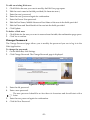
4.6.
Event Log History
The Event Log History page displays a log of events that have occurred within your system.
For each event you can view the date and time that the event occurred, a description of the
event, the user or device that caused the event and whether or not the event was reported to
your monitoring service. In addition to viewing the event log, you can also save the log to a
pre-formatted file or simply print the log.
To view the event log history:
On the Menu Bar, click History, the Event Log History Page is displayed:
Figure 21: Event Log History Page
To view images related to an event:
Click on the Image icon
displayed in front of the event. The selected event image is
displayed.
Figure 22: Event Image
To save the event log:
Select the type of file you want to save (HTML, PDF or RTF) and click Save.
To print the event log:
Click Print Log (located in the bottom right hand corner underneath the event log table).
-36-
4.7.
Home Automation
The Web Application allows you to control and schedule automated lights and
appliances in your home. The application offers a comprehensive interface that enables
you to view the settings for all of your automated devices at once. Additionally, you can
add, edit or delete devices from the comfort of your PC.
Discuss this capability with your security service provider to determine if it is
applicable to your system.
-37-
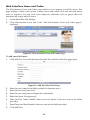
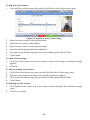
4.8.
Video Verification
Using the 2-way wireless PIR Camera detectors installed in your home, the Web
Application enables you to view still video images over the Web in order to check your
home and family while you are away.
To view the Video Verification page:
On the Menu Bar, click Video, the Video Verification Page is displayed:
Figure 23: Video Verification Page
The Video Verification page displays a list of your installed PIR camera detectors and
each device's descriptor (see Descriptors). The Web application provides the capability
to take an image on request for each PIR camera detector, view the stored image events
log and define camera settings.
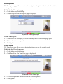
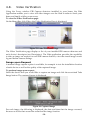
Image upon Request
A manual image capture option is available, for example to test the installation location
of each device as well as the quality of the captured image.
To perform image upon request:
Select the device that you would like to capture an image and click the associated Take
Image button. The captured image is displayed.
Figure 24: Captured Image
For each image, the following is displayed; the date and time that the image occurred,
the user or device that caused the event and the image location.
-38-
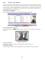
Stored Image Events
The Web application provides the capability to view the stored image events. The Stored
Image Events page displays a log of image events that have occurred within your
system. For each event you can view the date and time that the event occurred and the
user or device that caused the event.
To view the image event log:
From the Video Menu Bar, click Images; the Image Event Log Page is displayed:
Figure 25: Stored Image Events Page
To view the stored event image:
Click the relevant stored image event. The Stored Event Image is displayed.
Figure 26: Stored Event Image
For each stored image, the following is displayed; the date and time that the event
occurred, the user or device that caused the event and the event location.
-39-
Settings
The Web application provides the capability to modify the PIR camera detectors
parameter settings according to your needs
To view the video verification settings page:
From the Video Menu Bar, click Settings; the Video Verifications Settings Page is
displayed:
Figure 27: Video Verification Settings Page
To modify the PIR camera detectors parameter settings:
1. Modify the following parameter settings in the Video Verification Settings page:
Resolution
Quality
Color
Flash
Total Snapshots
Time between snapshots
(0.1 to 2 seconds)
2.
Select the required image resolution (QVGA 320X240,
VGA 640X480)
Select the required image quality (High, Low)
Select the required color setting:
Colour – checked,
B&W – unchecked
Select the required flash setting:
Flash – checked
No flash – unchecked
Enter the number of images that are required upon an
alarm (1 to 7)
Define the time interval between snapshots
Click Save.
Discuss this capability with your security service provider to determine if it is applicable
to your system.
-40-
5.
Panic Alarms
Panic alarms enable you to send a message to the monitoring service in the event of an
emergency. There are various types of panic alarm and several methods you can use to
generate them.
5.1.
Keypad Alarms
To activate an SOS Panic alarm from the front panel or wireless LDC keypad:
Press and hold down the Home
Automation On and Off keys
simultaneously
To activate a Fire alarm from the front panel keypad or wireless LCD keypad:
Press and hold down keys 1 and
3 simultaneously.
To activate a Medical alarm from the front panel keypad or wireless LCD keypad:
5.2.
Press and hold down keys 4 and
6 simultaneously.
Keyfob Panic Alarm
To activate a Panic alarm using the four-button keyfob (EL-4717):
5.3.
Press the lower two buttons simultaneously
Medical/Panic Alarm
The one-button keyfob (EL-4711M/P) is designed to send a message to your monitoring
service in the event of a medical or panic emergency.
The transmitter is water-resistant and can be worn around the
neck as a pendant.
-41-
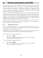
6.
Home Automation and PGM
Home Automation is an optional feature that requires an add-on expansion module.
Home Automation enables you to control up to 16 individual lights and appliances
around the home, in this section; we shall refer to these lights and appliances as HA
units and PGM output. The PGM is a programmable output that is triggered according
to specific system status conditions, or by remote command sent via PSTN, GSM,
Ethernet, keyfob, keypad, or Remote Programmer.
HA units and the PGM programmable output can be controlled (using the keypad and
keyfobs, remotely by telephone or SMS) or programmed to react to specific system status
conditions. For example, an HA unit can be programmed to switch on when the system
is armed or when a specific zone is triggered. Additionally, the Randomize feature is
designed to switch lights on and off at night when the system is armed. This gives
potential intruders the impression that the house is occupied.
Scheduling options enable you to program On and Off times for each HA unit. This
feature is found in the main menu. For further information on how to navigate the
menu, refer to Advanced System Operation.
6.1.
Keypad Control
Two keys on the keypad enable you to send On and Off commands to HA units, activate
and deactivate the PGM output. How HA/PGM units react to the On command is
determined by the installer in programming.
The HA/PGM unit can be programmed to switch on until the Off command is received
or automatically switch itself off after a pre-programmed amount of time.
To turn HA/PGM units on using the keypad:
1.
2.
.
Press the On key
Enter the two-digit HA/PGM unit number (01-16, or 30, 31 for PGM);
the chosen HA/PGM unit switches on.
To turn HA/PGM units on using the keypad:
1.
2.
.
Press the Off key
Enter the two-digit HA/PGM unit number (01-16, or 30, 31 for PGM);
the chosen HA/PGM unit switches off.
-42-
6.2.
Keyfob Control
You can control two separate HA units, using the four-button keyfob. This option can be
programmed by the installer. For further information on keyfob button assignments
refer to Keyfobs.
6.3.
Telephone Control
Using the Telecontrol feature, you can control HA units and PGM output remotely via
the telephone. For further information on the Telecontrol features, see Telecontrol.
6.4.
SMS Control
If your system supports cellular communication, you can control HA units and PGM
remotely via your mobile phone using a number of SMS commands. The SMS
commands are designed to be entered as templates on your mobile phone.
Each SMS command contains the following elements:
SMS Command Descriptor (up to 43 characters long)
# (separates the descriptor from the actual command)
User Code
Command (0=Off, 1=On)
HA Unit Number (01-16, or 30, 31 for PGM)
The following example shows the format of an SMS command to switch on a water
boiler controlled by HA unit 08.
SMS Command Descriptor
B
O
I
L
E
R
User Code
O
N
#
1
2
3
On
4
1
Unit
0
8
Do not include the symbol ‘#’ in the descriptor as the system regards any text after this
symbol as part of the command. The SMS Command Descriptor is optional but you must
still enter the ‘#’ before the user code.
SMS Confirmation Message Format
After an SMS command is executed by the system, if programmed by your installer, a
confirmation message may be returned to your mobile phone. This message includes the
HA unit’s descriptor and the command that was sent. The following example shows the
confirmation message you receive for the sample command from the previous section.
B
O
I
L
E
-43-
R
-
O
N
6.5.
Scheduling (not relevant to PGM)
The Scheduling feature allows you to set an On and Off time for each HA unit. At these
times the system automatically switches the HA unit on and off. You can also choose the
days of the week that the schedule is active.
On Time
To edit an HA unit’s “On” Time:
1.
From the main menu, select HA Schedules [8].
2.
Select an HA unit.
3.
From the HA unit’s sub-menu, select On Time.
4.
Enter a time (HH:MM).
5.
Press √ when the desired setting is displayed.
Off Time
To edit an HA unit’s “Off” Time:
1.
From the main menu, select HA Schedules [8].
2.
Select an HA unit.
3.
From the HA unit’s sub-menu, select Off Time.
4.
Enter a time (HH:MM).
5.
Press √ when the desired setting is displayed.
Weekly Schedule
To program the days of the week that the schedule is active:
1.
From the main menu, select HA Schedules [8].
2.
Select an HA unit.
3.
From the HA unit’s sub-menu, select Schedule.
4.
Use keys 1 to 7 to toggle the days on and off.
Press…
5.
To toggle…
Press…
To toggle…
1
Sunday
5
Thursday
2
Monday
6
Friday
3
Tuesday
7
Saturday
4
Wednesday
Press √ when the desired setting is displayed.
-44-
7.
Telecontrol
The iConnect
Control System offers a range of Telecontrol features that provide
remote access via the telephone. These features include Two-Way Audio, remote
arming/disarming and siren cancel.
Two-Way Audio
You may use the Two-Way Audio features to check your home in the event of an alarm
or as an alternative means of communicating with members of your family. For
example, you may wish to call an elderly person who has difficulty reaching the phone.
Using its Two-Way Audio features, the Control System automatically picks up the call
and you can communicate via its built-in microphone and speaker.
7.1.
Calling your Home
You may call your home at any time in order to contact your family, operate your
system or check your home while you are away. This feature is available for either
regular telephone communication or cellular communication.
Making a Call using a Regular Telephone
When your security system shares a telephone line with other devices (e.g. telephone
handsets, an answering machine or fax), it is important that the Control System
distinguish between calls so that it knows when to pick up the relevant call. For this
employs a double call method.
purpose the iConnect
To make a call to the Control System using the double call method:
1.
Dial your telephone number.
2.
Wait for two or three rings then hang-up.
3.
Wait at least five seconds and dial the number again; on the second
ring, the Control System picks up and sounds two tones.
Making a Cellular Call to the System
If your system supports cellular communication, it has its own individual telephone
number. Therefore, the double call method is not necessary and you may call the Control
System directly.
-45-
Call Procedure
To prevent unauthorized attempts to call your Control System, you must enter a user
code when calling your home – see User Codes, Code 29.
To call your home:
1.
Call the Control System either using the double call method or directly (see
above); when the Control System picks up, two tones are sounded.
2.
Enter the Telecontrol code (Code 29) on your telephone within 15 seconds.
Do not enter your user code until you hear the two tones. Any digits entered before the
tones are sounded are disregarded by the system.
3.
A tone is sounded to indicate that the system is ready to receive commands.
The following commands are available:
Press “2” for Two-Way Audio.
If the TWA mode is defined as “Simplex” (see Simplex Mode), the
audio channel opens in Listen mode (microphone active/speaker
mute). To switch to speak mode, press “1” on your telephone. To
switch back to Listen mode, press “0” on your telephone.
During the TWA session, you can adjust the speaker volume
using the arrow buttons.
Press “3” to fully arm the system.
Press "4XX" to turn HA unit #XX ON.
Press "430" to activate PGM output (Unit 30, 31)
Press "5XX" to turn HA unit #XX OFF.
Press "530" to deactivate PGM output (Unit 30, 31)
Press “6” to disarm the system.
Press “9” to cancel the siren.
The commands “3” (Full Arm), “4” (HA/PGM On), “5” (HA/PGM Off),
“6” (Disarm) and “9” (Bell Cancel) can also be executed at any time
during a Two-Way Audio session.
Error beeps (three tones) are sounded in case of a wrong command.
To clear the last command, press “” or “#”.
4.
5.
The duration of the call is an option programmed by your installer. Ten
seconds before the end of the call, two short tones are sounded. To extend the
call, press “7” on your telephone.
To disconnect before the end of the call, press “” then “#” on
your telephone.
Siren Muting
The siren is muted during Two-Way Audio communication. At the end of the call, the
siren is re-activated (if the Siren Cut-Off has not yet expired). You can cancel the reactivation of the siren by pressing “9” on your telephone during the call.
-46-
7.2.
Service Call
The Service Call feature enables you to call the monitoring service by pressing one key.
To make a Service Call:
Press and hold down the Service Call key
for a few seconds.
If using Simplex mode, the call is connected in Listen mode – see Simplex Mode.
7.3.
Two-Way Audio after an Alarm
In the event of Burglary, Fire and Emergency alarms, the Control System is able to report
the events and then stay on the line. This allows the monitoring service to verify the
alarm or provide assistance in the event of an emergency.
7.4.
Two-Way Audio Follow-Me
This feature causes the Control System to call you in the event of an alarm so that you
may check your family and home.
When the Control System calls, you will hear two short tones when you pick up the
phone. Press "2" on your telephone to answer the call.
If you press “9” to answer the call, the Control System simultaneously cancels the siren
when you answer the call.
If using Simplex mode, the call is connected in Listen mode – see Simplex Mode.
7.5.
Simplex Mode
It is possible that the Two-Way Audio features on your system are programmed to
operate in “Simplex” mode. Simplex mode means that one party may speak while the
other party listens.
If using Simplex mode, the call is connected in Listen mode. In Listen mode, the
microphone on the Control System is turned on so that you can listen in. If you want to
switch to Speak mode, press “1” on your telephone.
In Speak mode, the microphone is turned off and the speaker is turned on so that you
can speak to the person on the other end of the line. If you want to switch back to Listen
mode, press “0” on your telephone.
-47-
8.
Advanced System Operation
Besides the basic functions described in the previous chapters, you can access additional
functions via the menu. This chapter describes these functions and the menu navigation
procedure.
Menu Navigation
Using the LCD keypad on the front panel, you can navigate through the menus using
the menu navigation keys (/) and make simple yes/no decisions using the √ and Χ
keys.
The availability of menu items depends on the user code that you used to enter Menu
mode. Some menu items are limited to the Master code only (User 1). Certain menu
items, such as system programming functions, are not intended for the user and can
only be accessed by the installer.
The following example explains the procedure for Event Log viewing (Master code
access only).
1.
2.
Press √ to enter Menu mode.
Enter the Master code; the first menu item in the main menu, Cancel
Report is displayed.
3.
Press until 6. Event Log is displayed.
4.
Press √ to enter the Event Log menu; 1. View Log is displayed.
5.
Press √ to choose the displayed item.
Press Χ if you do not want to choose the displayed item. Pressing Χ also takes you back
to the previous menu level.
Menu mode automatically terminates two minutes after the last keystroke.
Throughout this chapter, we have tried to include all of the system functions using a
similar structure and order as they appear in the menu. The above procedure provides a
detailed explanation of menu navigation. However, in order to simplify the procedures
that appear in the rest of this chapter, the following conventions are used:
This…
Means…
From the Bypass Zones
menu, select Unbypass
All.
Enter the main menu by pressing √and entering your user
code. Using the arrow keys, navigate until you reach Bypass
Zones and press √. Using the arrow keys, navigate until you
reach Unbypass All and press √.
Select…
Use the arrow keys to scroll through the options and press √.
[61]
The shortcut to a specific menu item from the main menu. In
this case, this is the shortcut for View Log. These appear in
the procedures as an additional aid to menu navigation.
-48-
8.1.
Cancel Report
The Cancel Report function enables you to prevent the system from reporting in the
event of a false alarm.
To cancel report:
8.2.
From the main menu, select Cancel Report [1]; all pending messages to
the monitoring service are canceled.
Zone Bypassing/Unbypassing
When a zone is bypassed, its detector is ignored by the system and does not generate an
alarm when triggered.
To bypass or unbypass a zone:
1.
From the Bypass Zones menu, select Bypass/Unbyp. [21].
2.
Using the arrow keys, scroll to the zone you want to bypass or
unbypass.
3.
Press √ to change the bypass status.
4.
Press Χ; Save Changes? is displayed.
5.
Press √ to confirm the changed bypass status.
To unbypass all zones:
1.
From the Bypass Zones menu, select Unbypass All [22].
2.
Press √; all zones are unbypassed
All bypassed zones will be automatically unbypassed when the system is disarmed.
A fire zone cannot be bypassed.
-49-
8.3.
User Codes
The iConnect
supports a variety of individual user codes. Each of these codes is four
digits long. Most system functions require you to enter a valid user code.
The ability to perform a function is defined by your user code’s authorization level.
These authorization levels are pre-defined for each code as explained below.
Code 1: Master Code
The Master code is the highest user authorization level. With the Master code, you can
edit all other user codes. Additionally, the Master code grants access to the Event Log,
the Service menu and Home Automation Schedule programming.
The default Master code is 1234. Change this code immediately after the system has
been installed.
Codes 2-19: Controlled Codes
When you use a controlled user code for arming and disarming, the system notifies the
monitoring service.
Codes 20-25: Non-controlled Codes
Non-controlled codes do not cause the system to send Arm/Disarm reports to the
monitoring service. The system sends a Disarm report only if you use this code to
disarm the system after an alarm occurrence.
Codes 26-27: Limited Codes
A Limited code enables you to issue a code that is valid for one day only. This code
automatically expires 24 hours after it has been programmed.
Code 28: Duress Code
The Duress code is designed for situations where you are being forced to operate the
system. This user code grants access to the selected operation, while sending a Duress
event message to the monitoring service.
Code 29: Telecontrol Code
The Telecontrol code is designed to enable the user to perform a number of tasks via
their telephone using DTMF commands. Using this code, the user can call their system
to arm and disarm, turn on and off HA units, activate and deactivate the PGM output,
cancel the siren or establish Two-Way Audio communication. This code can only be
used for this specific purpose and does not grant access to any additional system
functions such as disarming.
-50-
Editing User Codes
User code editing is a feature that is available exclusively to the Master code. To
maintain a high level of security, keep all user codes confidential.
To edit a user code:
1.
From the main menu select, User Codes [4].
2.
Select the code you want to edit;
3.
From the code’s sub-menu, select Edit Code; the 4-digit code is
displayed with the cursor flashing on the first digit.
4.
Edit the code.
5.
Press √; the new code is stored in the memory.
If you enter a code that is identical to an existing user code, the Control System sounds
an error tone and the new code is not accepted. 0000 is not a valid user code as this
value is used to delete a user code.
Deleting User Codes
As an additional security measure, make certain that you delete any extra codes that are
no longer required.
To delete a user code:
1.
From the main menu select, User Codes [4].
2.
Select the code you want to delete;
3.
From the code’s sub-menu, select Edit Code; the 4-digit code is displayed with
the cursor flashing on the first digit.
4.
Enter 0000.
5.
Press √; the code is deleted.
The Master code cannot be deleted.
User Code Descriptors
Using the alphanumeric keypad on the front panel, you can edit the 16-character user
code descriptors and enter the name or title of the users to whom the code is allocated.
To enter text, press a key repeatedly to scroll through the characters that appear on the
key. For example, press 6MNO to enter M, N, O, or 6 respectively. You can also use the 1
and 0 keys to enter symbols. After you enter text, the cursor automatically moves to the
next character. During descriptor editing, use the left SOS button
before the current character. Use the Right SOS button
character.
To edit a user code descriptor:
1.
From the main menu, select User Codes [4].
2.
Select a code.
3.
From the code’s sub-menu, select Descriptor.
4.
Edit the descriptor using the alphanumeric keypad.
-51-
to enter a space
button to delete the current
5.
8.4.
Press √ when you have finished editing.
Follow-Me
The Follow-Me feature is designed to notify the user that certain events have occurred.
The events that are sent to the Follow-Me telephone number are those events that the
user is authorized to view in the event log; events that can be viewed only by the
installer are not sent to the Follow-Me number – see Two-Way Audio Follow-Me. If
using the TWA Follow-Me feature, the audio channel is opened after alarm events only.
To edit the Follow-me number:
1.
From the main menu, select Telephone # [5].
2.
Enter a telephone number for Follow-Me communication. If using the SMS
Follow-Me feature, this number must be for a cellular phone with the capability
to receive SMS messages.
You may only access Follow-me programming if the protocol for Account 3 is
programmed as SMS or TWA Follow-me.
8.5.
Event Log
The event log records events that have occurred within your security system. When the
log is full, the oldest events are automatically erased and are replaced by new events.
To view the event log:
1.
From the Event Log menu, select View Log [61]; the most recent event is
displayed.
2.
3.
4.
to display the Time/Date stamp or the default
Press the left SOS button
descriptor on the second row of the display.
Use the arrow keys to scroll through the events.
When you have finished viewing, press Χ to exit the log.
The event log displays the following information
for each event:
The event – a brief description of the event that occurred.
Zone descriptor – exactly where the event occurred.
Time/date stamp – the exact time the event occurred.
Report details – a single character indicating whether the
event was reported to the central station. The options
available are R: Report Sent, F: Report Failed or N: No
Report.
Default descriptor – in this case the number of the zone.
The above example shows the event log entry for a Fire alarm in the Kitchen (Zone 4) on
November 14th 2008. The report was successfully reported to the central station.
-52-
8.6.
Service Menu
The Service menu includes various functions that enable you to test your system
effectively. You can gain access to the Service menu using the Master code.
Set Time & Date
To set the time:
1.
From the Service menu, select Set Time/Date, Set Time [7011].
2.
Enter the current time.
3.
Press √; the time is modified.
To set the date:
1.
From the Service menu, select Set Time/Date, Set Date [7012].
2.
Enter the current date.
3.
Press √; the date is modified.
The format of the time and date is defined by your installer in programming. If you are
setting the time in 12hr format, use the
key to toggle between AM and PM.
Message Center
The Message Center is designed to allow you to record a short message that may be
played back later by another user. After a message is recorded, Message Waiting is
displayed on the LCD until the message is played back.
To play back a recorded message:
From the Service menu, select Messages, Play Message [7021].
To record a message:
1.
From the Service menu, select Messages, Record Message [7022].
2.
Press √ to start recording the message.
3.
Record your message. The message may be up to twenty seconds long.
4.
Press √ to stop recording; the message is automatically played back and OK? is
displayed.
5.
Press √ to save your recording.
To delete a message:
1.
From the Service menu, select Messages, Delete Message [7023]; OK? is
displayed.
2.
Press √; the message is deleted.
The Record and Play options can also be accessed via a convenient shortcut without
needing to enter a valid user code.
To access the Record Message option from Standby mode, press then Χ.
To access the Play Message option from Standby mode, press then √.
-53-
Siren Tests
To test the external wireless siren:
From the Service menu, select Test and then WL Siren Test [7031]; the wireless
siren is sounded briefly.
To test the built-in siren:
From the Service menu, select Test and then Siren Test [7032]; the built-in siren is
sounded briefly.
Interface Test
The Interface test enables you to check if the speaker, LEDs and LCD are functioning
correctly.
To test the system interface:
From the Service menu, select Test and then Interface Test [7033]; a short
sequence of chimes are sounded from the speaker, all LEDs flash and the LCD
is tested on all connected LCD keypads.
Walk Test
Walk Test mode enables you to test all the detectors registered to your system without
triggering an alarm.
To initiate Walk Test mode:
1.
From the Service menu, select Test and then Walk Test [7034]; a list of
registered detectors appears.
2.
Trigger each detector; when the system receives a successful transmission from
a detector, the detector is removed from the list.
3.
When all the detectors are removed from the list, End Walk Test is displayed.
4.
Press Χ to exit Walk Test mode.
Snapshot Test
The Snapshot Test enables you to check if the PIR Camera detectors are functioning
correctly
To initiate the Snapshot Test:
1.
From the Service menu, select Test and then Snapshot Test [7035]; a list of
registered PIR Camera detectors appears.
2.
Select a detector from the list and press √; a snapshot of the monitored area in
taken and the results can be viewed in the Web User Application.
3.
Repeat the test for each installed detector.
4.
Press Χ to exit Snapshot Test mode.
-54-
Transmitters
The Transmitters menu offers a number of testing utilities, TX List, TX Test, RF Link and
ENV. RSSI.
The TX List comprises all registered transmitters and their last reported status.
To view the TX list:
1.
From the Service menu, select Transmitters, TX List [7041]; the first
transmitter on the list is displayed.
2.
Using the arrow buttons, scroll through the transmitter list.
3.
When you have finished viewing, press Χ to exit the list.
The TX list displays the following information for
each transmitter:
This…
Means…
OK
The transmitter is functioning correctly
TA
Tamper condition
Notify
BT
Battery low
your
OS
The transmitter is out of synchronization
installer
NA
The transmitter is inactive
Press The left SOS button
to display the transmitter’s default descriptor.
-55-
The second utility, TX Test enables you to identify transmitters.
In TX Test mode, each time a transmission is received, a chime is sounded and the
activated transmitter is displayed.
To initiate TX Test mode:
1.
From the Service menu, select Transmitters, TX Test [7042].
2.
Activate a transmitter; the transmitter’s details are displayed.
3.
When you have finished, press Χ to exit TX Test mode.
Signal Strength
Tones
1
1 Tone
2
2 – Tones
3
3 Tones
4
4 Tones
The third utility, RF Link enables you to measure the RF noise levels between a selected
transmitter and the system’s receiver.
To view the Environment RF Link level reading:
1.
From the Service menu, select RF Link Test [7043]; the first transmitter
on the list is displayed.
2.
Using the arrow buttons, scroll through the list and select a
transmitter.
3.
Press √ and activate the selected transmitter, e.g. press keyfob button.
The RF noise levels of the selected transmitter and the system’s
receiver are displayed.
The fourth utility, Environmental RSSI enables you to measure the RF noise level of the
systems environment. The Control System will start measuring the RSSI level every
second, and it will display the result on the LCD.
RSSI level can jump momentarily when a detector is activated. It doesn’t mean that the
receiver is noisy.
To view the Environment RSSI level reading:
From the Service menu, select ENV. RSSI [7044]; the RF noise of the system's
environment is displayed.
-56-
Audio Volume
To adjust the sensitivity of the microphone and the volume of the speaker:
1.
Establish a two-way audio connection.
2.
From the Service menu, select Audio Volume [705].
3.
Adjust the setting according to the following table.
4.
Reading
Meaning
1
Increase microphone sensitivity
4
Reduce microphone sensitivity
3
Increase speaker volume
6
Reduce speaker volume
Press √; the new settings are stored in the memory.
GSM Signal Strength
You can measure the GSM signal strength.
To view the GSM signal strength reading:
From the Service menu, select GSM Signal [706]; the signal strength of
the cellular network is displayed.
Reading
Meaning
8-9
Reception is good
5-7
Reception is acceptable
Less than 5
Reception is unacceptable
Display Version
To display the system’s software and hardware versions:
From the Service menu, select Version [707]; the software (SW) and
(HW) versions are displayed.
Enable Programming
The Enable Programming command allows a user to limit access to system
programming. It means that the installer or Remote Programmer can access the system
only after a user with Master code provides authorization using the Enable
Programming command.
To enable this feature, contact your installer.
To grant access to the installer or Remote Programmer:
From the Service menu, select Enable Prog. [708]; a 30-minute time
window is opened during which the Installer Code is valid or RP
communication may be established.
-57-
Global Chime
Each detector can be programmed by your installer to cause the system to chime when
activated. This feature is active only when the system is disarmed. For example, the
system can be programmed to sound a chime each time the front door is opened or
closed. The Global Chime option enables you to turn this feature on and off.
To enable or disable Global Chime:
1.
From the Service menu, select Global Chime [709].
2.
Select either Enable or Disable.
3.
Press √ when the desired setting is displayed.
Global Chime can also be accessed via a convenient shortcut without needing to enter a
valid user code. To access the Global Chime option from Standby mode, press
then .
Remote Firmware Update
The Remote Firmware Update command enables a user with Master code authorization
to initiate the update from a remote PC using WEB communication.
Note: to enable this feature, contact your installer.
To initiate Remote Firmware Update:
From the Programming menu, select Service, Remote Software Update
[710]; a 24-hours time window is opened during which the Remote
Firmware Update may be performed.
IP Display
When using Ethernet connection, you can view the LAN IP address of the Control
System, i.e. the address that your home router has assigned to the Control System.
To display the IP Address:
From the Programming menu, select Service, IP Display [711]; the
LAN IP address of the Control System is displayed.
-58-
Appendix A: Menu Structure
-59-
Appendix B: Glossary
24hr Zone
A detector which is always active regardless of whether the system
is armed or disarmed.
Armed
The state during which the security system is activated. In most
cases, when the system is armed, triggering a detector generates an
alarm.
Arming Keys
The three keys on the front panel or keypad that activates one of the
system’s arming options.
Bypassed Zone
A detector which is ignored by the system. No alarm is generated
from a bypassed zone even if triggered when the system is armed.
A
B
C
Cancel Key
A key on the Wireless Keypad that causes the system to disregard
any partially entered code or command that may have mistakenly
been entered.
Cancel Report
An operation that clears all communication buffers and stops the
transmission of any pending messages to the monitoring service.
Cellular
Communication
Chime
Code
Monitoring and control via a cellular network.
A feature that provides audible annunciation when specific detector
s are activated.
See User Code
Controlled Code
A user code that causes the system to notify the monitoring service
when used to arm or disarm.
Delay
The exit/entry delay times that allow the user to arm or disarm the
system without generating an alarm.
Descriptor
Custom labels programmed for each user code, zone, keyfob,
keypad etc.
Disarmed
The state during which the security system is deactivated. During
disarm only detectors that are defined as 24hr, Panic, Medical, Fire,
Gas, Flood and Environmental are capable of generating an alarm.
Duress Code
A user code that generates a silent alarm to indicate that the user is
being forced to operate the system.
D
E
Entry Delay
See Delay
Event Log
A browsable record of events that have occurred within the system.
Exit Delay
See Delay
-60-
F
Follow-me
A feature that enables users to receive notification to their telephone
that an event has occurred in the system.
Forced Arming
Arming before the system is ready. If the system is not secured by
the time that the exit delay expires, an alarm is generated.
Front Panel
The main interface located on the front of the Control System
consisting of an LCD keypad.
Full Arming
An arming method that activates the entire system when the
premises are vacated.
G
Global Chime
A feature that enables/disables the Chime feature for the entire
system – see Chime.
HA Units
Home Automation Units (abbr.). The lights and appliances in the
home that are controlled by the optional Home Automation feature.
Home Automation
An optional feature that enables the user to control electrical
appliances and lights via the Control System.
Instant Arm
An arming method that cancels the entry delay after the system has
been Part or Perimeter armed.
Keyfob
Handheld wireless transmitters used to remotely control the system.
LAN IP Address
The address that your home router has assigned to the Control
System.
Limited Code
A user code that automatically expires 24 hours after it is
programmed.
H
I
K
L
Log
See Event Log
M
Master Code
The only user code with the ability to program other user codes. The
Master code also has exclusive access to specific system functions.
Medical Emergency
A type of alarm that informs the monitoring service that the user is
in need of medical assistance.
Message Center
An optional feature that enables users to record messages to be
played back by other users.
-61-
N
Non-Controlled
Code
A user code that does not cause the system to notify the monitoring
service when used to arm or disarm. The system only reports if the
code is used to disarm after an alarm.
O
One-Key Arming
Arming the system without the need for a valid user code.
P
Panic Alarm
A user initiated event that alerts the monitoring service in the event
of an emergency.
Part Arming
An arming method that is designed to activate a certain section of
the premises.
Perimeter Arming
An arming method that is designed to activate the detectors
protecting the doors and windows while enabling residents to move
freely on the premises.
PGM
Programmable output that is triggered according to specific system
status conditions, or by remote command sent via PSTN, GSM,
Ethernet, keyfob, keypad, or Remote Programmer.
R
Ready
The state in which all zones are closed and the system is ready to be
armed.
Remote Firmware
Update
Control System's firmware update from a remote PC using WEB
communication.
Restore
The restoral of a trouble condition to its normal state. For example, if
AC power is reconnected, an AC Loss Restore event code is sent to
the central station.
RSSI
Received Signal Strength Indication (abbr.) RF noise of the system's
receiver.
S
Scheduling
A Home Automation feature that switches HA units on and off
automatically according to pre-set times.
Detectors
The devices installed around the home that alert the panel in the
event of an alarm.
Service Call
A feature that enables the user to contact the monitoring service and
talk to an operator via the Control System.
SMS Command
An SMS message sent to the Control System that causes the system
to perform a specific function.
Smartkey
An RF ID device used to arm and disarm the system by placing it
against the Wireless Keypad.
SMS Confirmation
An SMS message sent to the user confirming that the SMS command
has been performed.
System Status LEDs
Luminous indicators on the front panel that provide information on
the arm and power status of the system.
-62-
T
Telecontrol
Tones
Trouble Tones
TWA
TX
A feature that provides remote access via the telephone including
remote arming/disarming, siren cancel and Two-Way audio.
Chimes sounded by the Control System’s internal or external siren.
Tones sounded by the system to indicate a trouble condition.
Two-Way Audio (abbr.)
Transmitter (abbr.)
TX List
A service feature that lists all the system’s registered transmitters,
their last recorded status and signal strength.
TX Test
A service feature that displays the source of the last received
transmission.
U
Unbypass
The restoral of a bypassed zone to its original state.
User Code
A four-digit code that grants access to certain system functions such
as arming and disarming the system.
User TWA Code
A user code that enables Two-Way Audio communication.
W
Walk Test
A mode that enables detectors to be tested without generating an
alarm.
Web Remote
Programmer
Software that enable installers or service providers to operate and
program the system from a PC either on-site or from a remote
location.
Wireless Keypad
Intelligent two-way wireless keypad with large LCD display that
serves as an additional user interface of the Control System.
Z
Zone
Zone Bypassing
A protected area within the security system.
See Bypassed Zone
-63-
Electronics Line 3000 Ltd. Limited Warranty
EL and its subsidiaries and affiliates ("Seller") warrants its products to be free from defects in
materials and workmanship under normal use for 24 months from the date of production.
Because Seller does not install or connect the product and because the product may be used in
conjunction with products not manufactured by the Seller, Seller cannot guarantee the
performance of the security system which uses this product. Sellers' obligation and liability
under this warranty is expressly limited to repairing and replacing, at Sellers option, within a
reasonable time after the date of delivery, any product not meeting the specifications. Seller
makes no other warranty, expressed or implied, and makes no warranty of merchantability or
of fitness for any particular purpose. In no case shall seller be liable for any consequential or
incidental damages for breach of this or any other warranty, expressed or implied, or upon
any other basis of liability whatsoever. Sellers obligation under this warranty shall not include
any transportation charges or costs of installation or any liability for direct, indirect, or not be
compromised or circumvented; that the product will prevent any persona; injury or property
loss by intruder, robbery, fire or otherwise; or that the product will in all cases provide
adequate warning or protection. Buyer understands that a properly installed and maintained
alarm may only reduce the risk of intruder, robbery or fire without warning, but is not
insurance or a guaranty that such will not occur or that there will be no personal injury or
property loss as a result. Consequently seller shall have no liability for any personal injury,
property damage or loss based on a claim that the product fails to give warning. However, if
seller is held liable, whether directly or indirectly, for any loss or damage arising from under
this limited warranty or otherwise, regardless of cause or origin, sellers maximum liability
shall not exceed the purchase price of the product, which shall be complete and exclusive
remedy against seller. No employee or representative of Seller is authorized to change this
warranty in any way or grant any other warranty.
WARNING: This product should be tested at least once a week.
CAUTION: Risk of explosion if battery is replaced by an incorrect type. Dispose of used
batteries according to local regulations.
Contacting Electronics Line 3000 Ltd.
International Headquarters:
Electronics Line 3000 Ltd.
14 Hachoma St., 75655
Rishon Le Zion, Israel
Tel: (+972-3) 963-7777
Fax: (+972-3) 961-6584
All rights reserved.
No part of this document may be reproduced in any form without prior written permission from
the publisher.
Electronics Line 3000 Ltd. 01/2013
5IN1772 B
-64-