1
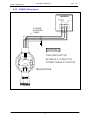
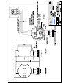
HLM-2000-EX
Flammable Gas Transmitter
User Manual
Technical Support
Continental North America Toll Free 1-(800) 387-9487
Ph: +1 (905) 829-2418 Fx: +1 (905) 829-4701
A Product of Arjay Engineering Ltd.
Oakville, Ontario, Canada
www.ArjayEng.com
www.EnmetGasDetection.com
HLM-2000-EX UM01.doc
Model: HLM-2000-EX
1
Rev: 1.0
TABLE OF CONTENTS
Section Title
Page
1
TABLE OF CONTENTS..................................................................................................1
2
WARRANTY....................................................................................................................2
3
2.1
LIABILITY...........................................................................................................2
2.2
PRODUCT RETURN .........................................................................................2
2.3
MODIFICATIONS AND SUBSTITUTIONS........................................................2
PRODUCT INFORMATION ............................................................................................3
3.1
TRANSMITTER..................................................................................................3
3.2
FACTORY SETTINGS.......................................................................................3
3.3
CONTAMINANTS & INTERFERANTS ..............................................................3
3.4
4
3.3.1
CONTAMINANTS................................................................................3
3.3.2
INTERFERANTS .................................................................................4
OPTIONAL ACCESSORIES..............................................................................4
PRODUCT DESCRIPTION.............................................................................................5
4.1
GENERAL DESCRIPTION ................................................................................5
4.1.1
5
6
INSTALLATION...............................................................................................................6
5.1
LOCATION.........................................................................................................6
5.2
MOUNTING........................................................................................................6
5.3
CABLE SELECTION AND WIRING...................................................................7
5.3.1
FIGURE: Cable selection chart. ..........................................................7
5.3.2
FIGURE: Wiring layout. .......................................................................8
OPERATION AND CALIBRATION .................................................................................9
6.1
OPERATION ......................................................................................................9
6.2
CALIBRATION ...................................................................................................9
6.2.21
6.3.1
EQUIPMENT REQUIRED ...................................................................9
CALIBRATION PROCEDURE ...........................................................................10
6.3.1
7
SENSOR / TRANSMITTER SPECIFICATIONS .................................5
MEASURING SENSOR SWING .........................................................10
PREVENTIVE MAINTENANCE ......................................................................................12
7.1
GENERAL ..........................................................................................................12
7.2
TROUBLESHOOTING GUIDE ..........................................................................12
7.3
SENSOR REPLACEMENT................................................................................13
7.3.1
FIGURE: Sensor replacement and wiring procedure..........................13
1
Model: HLM-2000-EX
2
HLM-2000-EX UM01.doc
Rev: 1.0
WARRANTY
This Arjay Engineering Ltd. equipment is warranted against defects in material and
workmanship from the date of shipment from factory. Please check equipment specifications
following this page for particular warranty periods. Maintenance items are not warranted. During
the warranty period, The Arjay Engineering Ltd. will repair or replace components that prove to
be defective in the opinion of Arjay. Any equipment deemed to be defective by the user should
be returned to The Arjay Engineering Ltd. for evaluation (see product return below). Site visits
by Arjay Engineering Ltd. personnel, to evaluate / repair equipment, are not covered by
this warranty. Arjay is not liable for auxiliary interfaced equipment, nor for consequential
damage. This warranty shall not apply to any product, which has been modified in any way,
which has been repaired by any other party other than a qualified technician or authorized Arjay
representative, or when failure is due to misuse or conditions of use.
2.1
LIABILITY
All ARJAY products must be installed and maintained according to instructions. Only qualified
personnel should install and maintain the equipment.
ARJAY shall have no liability arising from auxiliary interfaced equipment, for consequential
damage, or the installation and operation of this equipment. ARJAY shall have no liability for
labor or freight costs, or any other costs or charges in excess of the amount of the invoice for
the products.
THIS WARRANTY IS IN LIEU OF ALL OTHER WARRANTIES, EXPRESSED OR IMPLIED,
AND SPECIFICALLY THE WARRANTIES OF MERCHANTABILITY AND FITNESS FOR A
PARTICULAR PURPOSE. THERE ARE NO WARRANTIES THAT EXTEND BEYOND THE
DESCRIPTION ON THE FACE THEREOF.
WARNING
CHECK TO ASSURE THE WORKING AREA IS FREE FROM HAZARDS DURING
INSTALLATION OR WHEN PERFORMING MAINTENANCE, AND USE PROPER
PRECAUTIONS.
2.2
PRODUCT RETURN
All products returned for warranty or service should be shipped by prepaid freight and will be
accepted only with an R.M.A. number issued by ARJAY. All products returned to the client will
be shipped by freight collect.
2.3
MODIFICATIONS AND SUBSTITUTIONS
Due to an ongoing development program, ARJAY reserves the right to substitute components and
change specifications at any time without incurring any obligations.
2
Model: HLM-2000-EX
HLM-2000-EX UM01.doc
3
PRODUCT INFORMATION
3.1
TRANSMITTER
Rev: 1.0
Sensor/transmitter Unit Order Number ……………………
Transmitter Part Number / WARRANTY……………………
Transmitter Serial Number.….………………………………
Sensor Part Number / WARRANTY….…………………….
Sensor Serial Number………………………………………….
Power Supply Requirement…………………………………
12 to 26 VDC
Current Consumption……..………………………………….
300 mA max
3.2
FACTORY SETTINGS
Gas Type……………………………………………….…..….
Range 4 – 20 mA Scale………………………………..…….
Target Gas Ratio to Methane CH4..…………………………..
3.3
20% LEL CH4 =
%LEL
CONTAMINANTS & INTERFERANTS
3.3.1
CONTAMINANTS
The performance of Arjay Engineering Ltd. catalytic combustion type gas sensors may be
affected by exposure to substances known as poisons and inhibitors. Inhibitors are present in
volatile substances containing halogens or sulphur compounds. Sensors may recover their
sensitivity characteristics after exposure to inhibitors has ceased. Some substances produce a
permanent poisoning effect on the catalyst. These poisons include silicone oils, greases and
petroleum additives such as tetraethyl lead and phosphate esters. Always be cautious of by
products that may evolve from the thermal decomposition of materials such as plastics.
3
Model: HLM-2000-EX
3.3.2
Rev: 1.0
INTERFERANTS
Partial list of other gases that detector will respond to
Acetaldehyde
Acetic Acid
Acetic Anhydride
Acetone
Acetylene
Alkyl Alcohol
Ammonia
n-Amyl-Alcohol
Aniline
Benzene
Biphenyl
1, 3-Butadiene
n-Butane
iso-Butane
Butene-1
cis-Butene-2
trans-Butene-2
n-Butyl Alcohol
iso-Butyl Alcohol
tert-Butyl Alcohol
n-Butyl Benzene
iso-Butyl Benzene
n-Butyric Acid
Carbon Disulphide
Carbon Monoxide
Carbon Oxysulphide
Cyanogen
Cyclohexane
Cyclopropane
3.4
HLM-2000-EX UM01.doc
n-Decane
Diethylamine
Dimethylamine
2, 3-Dimethylpentane
2, 2-Dimethylpropane
Dimethylsulphide
1, 4-Dioxane
Ethane
Ethyl Acetate
Ethyl Alcohol
Ethylamine
Ethyl Benzene
Ethylcyclopentane
Ethylene
Ethylene Oxide
Dimethyl Ether
Diethyl Ether
Ethyl Formate
Ethylmercaptan
n-Heptane
n-Hexane
Hydrazine
Hydrogen Cyanide
Hydrogen
Hydrogen Sulphide
Methane
Methyl Acetate
Methyl Alcohol
Methylamine
Methylcyclohexane
Methylethylether
Methylethylketone
Methyl Formate
Methyl Mercaptan
Methylpropionate
Methyl n-propylketone
Napthalene
Nitromethane
n-Nonane
n-Octane
n-Pentane
iso-Pentane
Propane
n-Propyl Alcohol
n-Propylamine
Propylene
Propylene Oxide
iso-Propylether
Propyne
Toluene
Triethylamine
Trimethylamine
Vinylethylether
o-Xylene
x-Xylene
p-Xylene
OPTIONAL ACCESSORIES
The following options are available for your HLM-2000-EX Series Transmitter:
HLM-2000-EX 6000-08 Duct Adapter
HLM-2000-EX 6000-06 Splash Guard
Note: The use of optional accessories may
affect the response time.
HLM-2000-EX 6000-01 Flow Through Adapter
HLM-2000-EX 4309 Charcoal Filter
Poison resistant sensor.
Note:
All Arjay Engineering Ltd. Monitoring systems must be installed and maintained
according to instructions, to ensure proper operation. Only qualified personnel
should install and maintain the equipment.
4
Model: HLM-2000-EX
HLM-2000-EX UM01.doc
4
PRODUCT DESCRIPTION
4.1
GENERAL DESCRIPTION
Rev: 1.0
The ARJAY HLM-2000-EX series sensor/transmitter is designed to provide continuous, reliable
surveillance of surrounding air for combustible gases (listed in Product Information, page 3).
This unit provides a 4 to 20 mA, variable current signal, which is proportional to the gas
concentration detected. Each sensor/transmitter is factory calibrated and ready for field
installation and operation.
4.1.1
SENSOR / TRANSMITTER SPECIFICATIONS
OPERATING TEMPERATURE:
–40 to +40 ºC (–40 to +104 ºF)
OPERATING PRESSURE:
Ambient atmospheric pressure.
HUMIDITY:
0 to 99% RH, non-condensing.
SIGNAL OUTPUT:
4 to 20 mA into 250 Ohms maximum.
CERTIFICATION:
CSA C-22.2 #152-M1984
SENSOR TYPE:
Catalytic pellistor.
RESPONSE TIME:
50% < 10 secs ; 90% < 30 secs
ZERO DRIFT:
Less than 3% full scale per month.
SENSOR LIFE:
2 to 5 years in clean air.
5
Model: HLM-2000-EX
5
INSTALLATION
5.1
LOCATION
HLM-2000-EX UM01.doc
Rev: 1.0
To select a suitable instrument and effective location to properly safeguard any particular area
the user must have a basic knowledge of gas / vapor properties and phenomena as to how
gases and vapors propagate and whether the gases are heavier or lighter than air. The user
must also be aware of the conditions which may prevail in the areas being protected such as
the direction and velocity of gas movement, humidity and temperature variation, presence of
particulates or detrimental contaminants and ease of gaining access for periodic instrument
maintenance and adjustment.
The following points will aid the user in selecting a solid non-vibrating mounting surface subject
to the general location dictated by industry standards and the regulatory authorities.
1) Density of gases to be monitored.
Lighter than air vapors / gases tend to rise and heavier than air vapors / gases
tend to settle.
2) Air movement.
Air velocity and direction influence the dispersion of vapors / gases to be
monitored.
3) Potential sources.
The location and nature of the potential vapor / gas sources such as pressure,
amount, source temperature and distance need to be assessed.
4) Ambient temperature.
Avoid installation in environments likely to promote condensation.
5) Accessibility.
Future maintenance and calibration requirements should be considered when
selecting detector locations.
6) Structural arrangements.
Structural arrangements such as walls, troughs or partitions could allow vapor /
gas to accumulate.
7) Mechanical damage and contamination.
Detectors should be installed in locations to preclude mechanical damage from
cranes, traffic, exhausts and washdowns from normal operations.
5.2
MOUNTING
The sensor housing SHOULD NOT touch the mounting surface. Do not install the sensor facing
up. Please refer to the mounting installation diagram at the end of this manual.
Note: Refer to the electrical code for mounting regulations
The mounting arrangement of the transmitter housing, dependant on the transmitter
location and mounting surface, must comply with local electrical regulations and codes.
6
Model: HLM-2000-EX
5.3
HLM-2000-EX UM01.doc
Rev: 1.0
CABLE SELECTION AND WIRING
The transmitter output (–,S,+) terminal block connects to the (–,S,+) connections on a channel
terminal block of the monitor (one transmitter per channel), as shown in Figure 5.3.2.
Connection should be made using 3-conductor, shielded cable (shield is to be grounded at the
monitor and not grounded at the transmitter housing). Run cable through steel conduit for best
signal transmission. The maximum permissible distance between the transmitter and monitor is
dependant on wire gauge as shown in the following Cable Selection Chart.
5.3.1
FIGURE: Cable selection chart.
7
HLM-2000-EX UM01.doc
Model: HLM-2000-EX
FIGURE: Wiring layout.
MONITOR
MAX 250 OHM
INTERNAL
LOAD
+12 - 26
V DC
3-WIRE
SHIELDED
CABLE
_ S +
WARNING
+
CABLE SHIELD MUST NOT
BE USED AS A CONDUCTOR.
CONNECT SHIELD AT MONITOR.
_
S
POWER
CAL
AMC
5.3.2
Rev: 1.0
SPAN ZERO
_
SENSOR
+
2 1
TRANSMITTER
8
Model: HLM-2000-EX
HLM-2000-EX UM01.doc
6
OPERATION AND CALIBRATION
6.1
OPERATION
Rev: 1.0
The ARJAY HLM-2000-EX series sensor/transmitter is factory calibrated for the gas listed in
Factory Calibration at the beginning of this manual. The sensor/transmitter should not need recalibration when first installed and powered up, but a test for correct operation is suggested. All
testing should be done after the recommended stabilization period of 24 hours.
Following stabilization the transmitter should be sending, in a clean air environment, a 4 mA
signal to the monitor or controller. However, there are a few situations where a slightly higher or
lower than normal signal may be noticed. In many facilities there can be residual levels of the
gas being detected in the air at all times. These can cause a minor response from the sensor
expressed as a rise in signal. Other causes for minor signal variations include extremes in
temperature. The application of a clean air sample will verify if the elevated signal is from
background gas or equipment error.
6.2
CALIBRATION
Verification of calibration should be done at least once every 6 months for safety reasons.
Monthly verification is recommended for highly demanding applications.
Calibration is necessary after replacing the sensor. The new sensor requires an initial burn in
time of 24 hours.
Factory or on-site calibration services, customer training and calibration kits are available.
Specify the sensor / transmitter Part Number and Serial Number noted in section 3.1
TRANSMITTER and Gas Type noted in section 3.2 FACTORY SETTINGS to order any of the
above.
Note:
Turn off power supply before removing or replacing the transmitter or
sensor.
Caution:
Only qualified personnel should perform the calibration.
6.2.21 EQUIPMENT REQUIRED
•
digital multimeter with a minimum display range of 20.0 mA
•
remote calibration lead provided with the transmitter
•
miniature screwdriver
•
calibration kit : zero & span gases, regulator, hose & adapter cup
•
contact factory for information on cal kits
9
Model: HLM-2000-EX
HLM-2000-EX UM01.doc
Rev: 1.0
6.3.1 CALIBRATION PROCEDURE
The remote calibration lead is required to measure the transmitter output signal. The insertion of
the calibration lead plug into an HLM-2000-EX 3 wire model transmitter cal jack will disable the
transmitter output signal. This will result in a FAIL ALARM condition at the monitor during the
calibration / verification procedure.
Zero and Span adjustment terminals are provided to set the zero and span while the sensor is
exposed to known concentration sample gas mixtures. It is always best to calibrate the
transmitter with the intended gas to be detected. When this is not possible nor practical
theoretical cross sensitivity calibration may need to be used.
1) Remove cover from transmitter housing
2) Connect remote calibration lead to multimeter. BLACK lead to negative or common
(–). RED lead to positive (+) mA scale.
3) Switch ON multimeter and select the DC milliamp range of 20 mA or greater scale.
4) Insert plug end of remote calibration lead fully into CAL jack on transmitter cover
plate. This will block the outgoing signal and probably causing a “fail” at the monitor.
5) Apply a Zero gas sample or fill a garbage bag with clean outdoor air and apply to
sensor. Check for a stabilized ZERO signal of 4.0 mA. Set ZERO trimmer to 4.0mA.
6) Apply a Span gas sample. Since the transmitter output range is 4 to 20 mA, a fullscale concentration should register 20 mA after a few moments exposure.
Proportionately, a half-scale concentration of gas should register 12 mA, and so on.
For non-Methane target gas, see the specifications in section 3.2 FACTORY SETTINGS for the
Methane ratio. Methane at 20% LEL can be cross ratioed for most target combustible gases.
Apply the “span” gas and adjust the SPAN trimmer to the appropriate mA output. It is good
instrumentation practice to verify the zero reading after performing any span adjustments.
Perform the span procedure after all zero adjustments.
6.3.1
MEASURING SENSOR SWING
For ongoing monitoring of sensor condition you can check the sensor “swing” during calibration.
Sensor power supply is 2.0V between sensor terminals + and -. Signal “swing” is measured
between – and 1 terminals. Compare the clean air environment Voltage and the cal gas
environment Voltage. A new sensor will have approximately 0.75 mV swings per % LEL CH4.
Minimum swing should be 3 mV with 20% LEL CH4. For 50% LEL CH4 minimum swing would
be 7.5mV. Sensor swing data should be logged for performance evaluation and sensor
replacement purposes.
10
HLM-2000-EX UM01.doc
Model: HLM-2000-EX
Rev: 1.0
FROM MONITOR
DIGITAL
MULTIMETER
mA
DC
(CURRENT MODE)
ZERO
ADJUST
+
INSERT PLUG
INTO CAL JACK
_
S
POWER
mA Com
AMC
CAL
SPAN ZERO
_
SENSOR
2 1
+
SPAN
ADJUST
TRANSMITTER
SENSOR
" SWING "
LOCATION
SENSOR POWER
2.0 +- 0.1 V DC
REMOTE
CALIBRATION
LEAD
SENSOR
FIGURE: Calibration / verification set-up procedure.
SENSOR
AMC
_
+
_
S
POWER
CAL
SPAN ZERO
SENSOR
2 1
+
CALIBRATION
ADAPTER
REGULATOR
PLACE CALIBRATION ADAPTER INTO
CALIBRATION
GAS
CYLINDER
SENSOR ELEMENT AND OPEN
REGULATOR VALVE FULLY. ADJUST AFTER
STABILIZATION OF mA SIGNAL.
FIGURE: Calibration procedure.
11
HLM-2000-EX UM01.doc
Model: HLM-2000-EX
7
PREVENTIVE MAINTENANCE
7.1
GENERAL
Rev: 1.0
The enclosure should be brushed or wiped clean once a year or more, depending on the
accumulation rate of dust or dirt.
To avoid sensor damage, the unit MUST NOT be submerged in any liquids. Hosing or splashing
the unit with any liquids must also be avoided.
7.2
TROUBLESHOOTING GUIDE
Symptom
No Current
Output From TRX
Steady 1 mA
Output from TRX
Possible Cause
Power Supply
Problem
Blown Multimeter
Fuse
Excessively low
zero setting
(common if
changing sensor)
Failed sensor
Bad sensor
connection
Damaged sensor
Not enough
sensor response
with Cal gas,
cannot adjust or
correct span
output
Expired or weak
sensor
Not enough
sensor response
with Cal gas,
cannot adjust or
correct span
output
Expired or weak
sensor
Upscale zero
reading
Background gas
Short sensor life
Poisoned sensor
Test Action
Measure TRX supply voltage.
Should be between 12-26 VDC
Test meter fuse
Corrective Action
Isolate Power supply Problem
Attempt zero adjustment
Reset zero, readjust span also
Bad connection at sensor or
damaged sensor
Measure sensor signal voltage on
TRX sensor Terminal Block.
Voltage should be 2 VDC
between (+) and (-) and Approx. 1
VDC between (-) and (1)
Disconnect power, remove
sensor and measure sensor
voltage. Voltage should be 2 VDC
between (+) and (-) and Approx. 1
VDC between (-) and (1)
Measure sensor signal on TRX
sensor terminal block from (S)
and (-). A typical sensor has a net
signal change of 1 mV for every
percent LEL when new. Minimum
recommended swing is 3 mV with
20% LEL CH4.
Measure sensor signal on TRX
sensor terminal block from (S)
and (-). A typical sensor has a net
signal change of 1 mV for every
percent LEL when new. Minimum
recommended swing is 3 mV with
20% LEL CH4.
Apply zero gas or ensure a clean
air environment
Perform sensor tests as below
Calibrate sensor
12
Replace meter fuse
Ensure good connection
between sensor terminal block
and sensor
If sensor is open on any
combination of wires, call
factory for replacement sensor
Contact factory for replacement
sensor.
Contact factory for replacement
sensor.
Adjust zero if clean air does not
lower signal. Recheck span if
zero is adjusted.
If sensor life is shorter than
expected, a poison resistant
sensor may be more suitable
for the application. Contact an
ARJAY application consultant
at the factory
HLM-2000-EX UM01.doc
Model: HLM-2000-EX
7.3
Rev: 1.0
SENSOR REPLACEMENT
Sensor life is typically 2 to 5 years, depending on environmental conditions. The sensor should
be replaced under the following conditions:
1. If the sensor element becomes an open circuit, the transmitter outputs a fixed 1 mA
signal that cannot be readjusted.
2. When the sensor no longer responds to the presence of gas or produces an unstable
“zero” signal.
3. A recommended minimum of 3 mV sensor responses to 20% LEL of Methane is required
for stable reliable operation. Measure the sensor swing as per section 6.3.1.
When the sensor needs replacing, reorder the “Sensor Part Number” listed in the Product
Information on page 3. Refer to Figure 7.3.1 for the sensor replacement and wiring procedure.
Perform initial approximate calibration after a minimum of 15 minutes of sensor being powered.
Allow 24 hours for the new sensor element to stabilize (burn-in) before final
calibration. Refer to calibration section 6.3 of this manual.
Note:
7.3.1
FIGURE: Sensor replacement and wiring procedure.
FROM MONITOR
STEP 1 :
POWER DOWN
STEP 2 :
UNSCREW SENSOR
WIRING FROM
TERMINAL BLOCK.
TRANSMITTER
+
_
CAL
AMC
SPAN ZERO
UNTHREAD SENSOR
ASSEMBLY FROM
TRANSMITTER HOUSING
_
STEP 4 :
THREAD NEW SENSOR
ASSEMBLY ONTO
TRANSMITTER HOUSING.
SENSOR
SENSOR
2 1
+
YELLOW
RED
_
SENSOR
2 1
+
BLACK
STEP 3 :
S
POWER
STEP 5 :
CONNECT SENSOR LEADS
TO SENSOR TERMINAL
BLOCK ON TRANSMITTER.
RESTORE POWER.
WIRING
DETAIL
STEP 6 :
PERFORM INITIAL CALIBRATION
AFTER 15 MINUTES AND FINAL
RECALIBRATION (FINE TUNING)
AFTER 24 HOURS.
13
MAINTENANCE AND CALIBRATION
Your ARJAY / ENMET gas detector is the state of the art in gas detection, but like any other
part of your ventilation system, it requires periodic maintenance and calibration.
There are various sensor technologies that may be used in your Arjay gas monitor; including
solid state MOS, Electrochemical, Infrared and Pellister Pair (Hot wire). These have a normal
operating life of 3 to 5 years under ambient conditions. You should consider a preventive
maintenance schedule whereby you test your system on a periodic basis to ensure its proper
calibration and operation.
For solid state (MOS) sensors, we recommend calibration every 3 to 4 months for a typical
garage application. For Electrochemical sensors, we recommend calibration every 6 months for
a typical garage application. Pellister Pair we recommend every 3 to 4 months and Infrared we
recommend every 6 months. For applications that are more sensitive, or where internal policies
exist, a higher frequency of calibration may be required. This is a simple procedure which will
indicate any problems with your system. A test and calibration kit may be purchased from
ARJAY ENGINEERING for this purpose. Parts are also readily available from our facility.
MAINTENANCE CONTRACT
Alternatively you may wish to consider a Maintenance Contract with ARJAY ENGINEERING
whereby one of our service technicians comes to your site and checks out the unit for proper
calibration and operation on a regularly scheduled basis. This is done on a flat per annum fee.
All parts are extra. Typical target gases are included, however, exotic or specialty gases may
have a surcharge. If you wish us to quote a Maintenance Contract fill in the section below and
return to our office.
COMPANY:
ADDRESS:
CONTACT PERSON:
PHONE:
FAX:
EMAIL:
MODEL AND SERIAL
NO. OF GAS DETECTOR:
Fax to address below or e-mail to [email protected]
ARJAY ENGINEERING LTD
2851 Brighton Rd
Oakville, Ontario, Canada L6H 6C9
Telephone: +1 (905)-829-2418
Telefax: +1 (905)-829-4701
N. America Toll: (800)-387-9487
Internet: www.arjayEng.com
E-Mail: [email protected]
ARJAY ENGINEERING LTD.
GUARANTEE
We hereby guarantee this instrument to be free from defects in workmanship
and materials, and if found defective in workmanship or materials, upon
being returned to our factory, prepaid, within one year from date of purchase,
it will be repaired or replaced at factory without charge. However, if upon
being returned and after inspection, there is evidence that the instrument has
been subjected to tampering, careless handling, improper or faulty
application or installation, the above guarantee shall not be applicable, and we
shall have the right in any such case to make a charge to cover the cost of
repairs, servicing and transportation expense. The undersigned assumes and
shall have no liability for consequential damages resulting from the use or
misuse of the instrument.
The foregoing guarantee is in lieu of all other guarantees or warranties,
expressed or implied, and all other obligations or liabilities, contractual or
otherwise, either to the original purchaser of said instrument, or to any other
person whomever.
BY: ARJAY ENGINEERING LTD.
For service, call ARJAY Engineering Ltd. directly:
Canada (905) 829-2418
North American Toll Free:
1-800-387-9487
Fax:
(905) 829-4701
Internet:
www.arjayeng.com
E-mail:
[email protected]
ARJAY ENGINEERING LTD
2851 Brighton Rd
Oakville, Ontario, Canada L6H 6C9
Telephone: +1 (905)-829-2418
Telefax: +1 (905)-829-4701
N. America Toll: (800)-387-9487
Internet: www.arjayEng.com
E-Mail: [email protected]