1
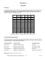
Product Specifications
Models:
USC-10001, USC-10002
USC-20001, USC-20002
USC-30001, USC-30002
Guide Specification for UniStar® C Series
Rack/Universal 1, 2, 3Kva
Single-Phase, On-Line Double Conversoin
Uninterruptible Power Supply
9-1-10
301 Gaddis Blvd, Dayton, OH 45403, USA
Telephone: (866) 261-1191, (937) 253-1191 Facsimile: (937) 253-1723
SECTION 1.0
SCOPE AND SYSTEMS RATINGS
1.1 Specification
This specification defines the electrical and mechanical characteristics and requirements for a
continuous duty, single-phase, rack and universal mount design uninterruptible power system. The
specification identifies 1Kva, 2Kva and 3Kva double conversion equipment, hereafter referred to as
the UPS.
The UPS shall utilize "true on-line” pulse width modulated (PWM) inverter incorporating Mosfet
Transistor technology. The inverter is a microprocessor controlled, solid-state device within the
uninterruptible power system. The uninterruptible power system, hereafter referred to as the UPS,
shall provide high quality AC power for sensitive electronic equipment loads.
The UPS shall consist of a rectifier/charger, battery, inverter, protective devices, static transfer
switch, synchronizing and phase lock circuitry, and controls required to provide regulated,
uninterrupted, conditioned power to the critical load.
The UPS shall include all mechanical and electrical devices that will automatically provide continuity
of electrical power within the defined limits without interruption, failure or degradation of the
commercial power source. Continuity of conditioned electric power shall be maintained for the
defined period of time by the battery system. Upon return of the utility power source, the UPS shall
automatically assume the load, while simultaneously recharging the batteries.
1.2 UPS Modes of Operation
The UPS shall be designed to operate as an on-line reverse transfer system in following modes:
1.2.1 Normal: The critical AC load is supplied continuously by the inverter. The rectifier/charger
derives power from a utility AC source and supplies DC power to the inverter while simultaneously
float charging a battery system. The inverter converts the DC power into clean and regulated AC
power that is then supplied to the critical load through the static transfer switch.
1.2.2 Emergency: Upon failure or degradation of the utility AC power, the critical AC load supplied
by the inverter will draw its power from the batteries. There shall be no interruption of power
switching from utility AC power to batteries or while switching from batteries back to utility AC power
upon its restoration. While the battery powers the UPS, indication for actual battery backup time
shall be provided.
1.2.3 Recharge: Upon restoration of utility AC power, even if the batteries are completely
discharged, the UPS will restart. The rectifier/charger shall assume the inverter and battery
recharge loads. If the bypass source is within acceptable limits, the UPS will retransfer the critical
load back to the inverter.
1.2.4 Bypass: When the inverter overload capacity is exceeded, the static transfer switch shall
perform a transfer of the load from the inverter to the bypass source with no interruption in power to
the critical load.
1.2.5 Maintenance Bypass: If for some reason the UPS has to be taken out of service for
maintenance or repair, the UPS shall be provided with an optional, external maintenance bypass
UniStar C Rack/Universal Guide Specifications
Pg. 2
1, 2, 3 kVA
switch to enable a load transfer from the inverter to the bypass source with no interruption of power
to the critical load.
1.3 System Ratings
Ratings
Voltage Range
120Vac
240Vac
60Vac –144Vac Software Selectable; 120Vac – 288Vac Software Selectable
Frequency
50/60 Hz Auto-Select, +/- 5Hz
Phase/Wire
Line + Ground
Power Factor
>0.99 at Rated Full Linear Load
Transfer Time
0 ms
AC Leakage Current
Surge Protection
< 5mA
|
400 joules
|
<3.5mA
300 joules
1.3.2 Output
Ratings
120Vac
Capacity
1kVA/700W | 2kVA/1400W | 3kVA/2100W | 1kVA/700 W | 2kVA/1400W | 3kVA/2100Watts
Voltage
100/110/115/120/127Vac Software Selectable | 200/208/220/230/240Vac Software Selectable
Voltage Regulation
Frequency
(Sync Range)
Frequency
Battery Mode
Crest Factor
Harmonic Distortion
Transient Response
Waveform
Efficiency AC Mode
Efficiency Bat. Mode
DC Start
Cooling
Over temperature
Overload
Full Load Heat
Rejection BTU/hr
|
120Vac
|
120Vac
|
240Vac
|
240Vac
| 240Vac
+/- 1%
3Hz or 1Hz Software Selectable
+/- 0.1% (0.05 ~0.06Hz)
3:1
< 3% THD (Linear Loads), < 7% THD (Non-Linear Loads)
< = 60ms/5%
Pure Sine Wave
85% |
85%
|
88%
|
85%
|
85%
|
88%
83% |
83%
|
85%
|
83%
|
83%
|
85%
Yes
Load Dependent Variable Speed Fans
Normal Mode – Transfer to bypass;
Battery Mode – UPS shuts down immediately
<105% continuous, >120% for 30 seconds, >150% for 10 seconds
422
843
977
422
843
977
1.3.3 Internal Battery
UniStar C Rack/Universal Guide Specifications
Pg. 3
1, 2, 3 kVA
Internal battery shall be maintenance-free sealed type to minimize the need for servicing. Battery
shall be hot-swappable design, allowing users to replace the batteries without the hazard of
electrical shock or interruption to the connected load. The UPS shall continue to supply power
during such servicing, as applicable.
Model
1kva/2kva 120V
Battery Run Time
@Full Load
7
3kva/120V
|
5
1kva/2kva 240V
|
7
3kva 240V
|
5
1kva
2kva
3kva
1kva
2kva
3kva
3 ea.12V/7AH | 6 ea.12V/7AH | 6 ea.12V/9AH | 3 ea.12V/7AH | 6 ea.12V/7AH | 6 ea.12V/9AH
Type
Charging Current
Charging Voltage
Hot – Swappable
Recharge Time
Extended Battery
DC Linkage Current
Battery Mgmt.
1.1 Amps
|
2.17 Amps |
41.0Vdc | 82.0Vdc |
+/-0.5V | +/-0.5V |
2.7 Amps | 1.1 Amps | 2.17 Amps | 2.7 Amps
82.0Vdc | 41.0Vdc |
+/-0.5V | +/-0.5V |
82.0Vdc |
+/-0.5V |
82.0Vdc
+/-0.5V
Yes
4 hours to 90%
Yes – Hot Swappable
<30uA (+/-10uA) with no AC applied and unit Off
Automatic Battery Management (ABM) saves battery life
SECTION 2.0
ENVIRONMENTAL
2.1 Environmental
Operating Temp:
0°C – 40°C
Altitude: 0 - 2,000 m up to 40° C. 3,000 m up to 35° C
Noise Level:
<50dBA @ 1 Meter
Relative Humidity:
0 to 90% non-condensing
SECTION 3.0
GENERAL REQUIREMENTS
3.1 System Description
3.1.1 Rectifier/Charger
The rectifier section of the power converter module capable of receiving utility input and rectifying
it to produce Direct Current (DC) power at levels sufficient enough to supply the load via the
inverter, and recharge the battery.
3.1.2 Inverter
The inverter section of the power converter module shall utilize power switching Mosfet Transistors.
This solid-state device that incorporates pulse width modulation (PWM) technology is capable of
accepting the output of the rectifier/charger or the battery system voltage and delivering AC power
within specified limits to the critical load bus. The inverter shall be microprocessor controlled and
include all necessary timing logic and control circuits.
UniStar C Rack/Universal Guide Specifications
Pg. 4
1, 2, 3 kVA
3.1.3 Static Transfer Switch
An internally mounted static transfer switch and bypass circuit shall be provided as an integral
part of the UPS. The static switch shall be high speed power electronic devices rated to conduct
full load current continuously while on inverter or bypass power. The static switch shall include
all necessary logic circuitry for fully automatic frequency synchronization and phase locking of the
UPS inverter output to the bypass/reserve power source.
SECTION 4.0
WIRING AND CONNECTION
Wiring practices, materials and coding shall be in accordance with the requirements of the National
Electric Code, NFPA 70 and other applicable codes and standards
Section 4.1 Description
Input/Output Connections
KVA
1
2
Vac
120
120
3
120
1
230
2
230
3
230
Input Cord
5-15P
Output Connection
(6) 5-15R
(2) 5-15R
(2) 5-20R
(4) 5-15R
(1) L5-30R
5-20P
L5-30P
(6) 10A
IEC320-C13
(6) 10A
IEC320-C13
(4) 10A
IEC320-C13
(1) – C19
(10A) IEC320-C14
(10A) IEC320-C14
(16A) IEC320-C14
Output Control: (2) ON/OFF Software controlled receptacle banks for load shedding
SECTION 5.0
MECHANICAL STANDARDS
5.1 Cabinet Description
The UPS unit, comprised of the rectifier/charger, inverter, static transfer switch shall be housed in
an enclosure offering indoor protection.
Dimensions Rack Configuration
H" x W" x D” Tower Configuration
1kva 3.5 x 17.4 x 16
1kva 17.4 x 3.5 x 16
2/3kva 3.5 x 17.4 x 25.6
2/3kva 17.4 x 3.5 x 25.6
1kva, 120V | 2kva, 120V | 3kva, 240V | 1kva, 240V | 2kva, 240V
Weight (lbs.)
35
|
64
|
65
UniStar C Rack/Universal Guide Specifications
|
Pg. 5
35
|
64
|
3kva, 240V
|
65
1, 2, 3 kVA
SECTION 6.0
MONITORING, CONTROLS, ALARMS AND COMMUNICATION
6.1 General
6.1.1 Control Panel
The UPS unit shall incorporate the necessary controls, instruments and indicators to allow the
operator to monitor the system status and performance, as well as take any appropriate action.
Display, Alarms, Diagnostics, Communications & Emergency Functions
Status On LCD
Line Mode, Backup Mode, ECO Mode, Bypass Supply, Battery Low,
Battery Bad/Disconnected, Overload, Transferring with interruption
& UPS Fault
Readings On LCD
Input Voltage, Input Frequency, Output Voltage, Output Frequency,
Load Percentage, Battery Voltage & Units Inner Temperature
Power Up
ON/OFF Button, Test Alarm & Reset Button
Self-Diagnostics
Upon Power –On, Front Panel Setting & Software Control,
24 Hour self check
Audible Alarms
and Visual
Communications
Emergency Power Off
(EPO) Connection
Line Failure, Battery Low, Transfer to Bypass, System Fault Conditions
RS232 Serial Port and USB, optional SNMP/WEB, USB or
Dry Contact Cards
Emergency Power Off shuts down UPS when activated by
customer supplied EPO Circuit
6.1.2 Communications
The communication port on the rear panel of the UPS shall be RS232 serial type, allowing
for computer connection to monitor the status of the UPS, and allow for the control and
operation of the UPS. Communication software will bundled with the UPS for use with
MS Windows
Section 7.0
Standards
7.1 Applicable Documents
The UPS shall be designed in accordance with the applicable sections of the current revision of the
following documents.
Safety/Performance UL1778, c-UL, CE, IEC/EN 62040-1-1, IEC 60950-1, IEC/EN 62040-2
Class A, FCC Part 15 Subpart B Class A (Note 230vac not UL, c-UL listed)
EMC Standards
IEC/EN62040-2 Class A, FCC Part 15 Subpart B Class A, IEC/EN55011,
CISPR11, IEC61000-4-2/-3/-4/-5, IEC61000-2-2, IEC61000-3-2/-3
UniStar C Rack/Universal Guide Specifications
Pg. 6
1, 2, 3 kVA
SECTION 8.0
OPTIONS
8.1 Battery
A storage battery shall be used to provide the system with extended operational run times. Battery shall be
hot-swappable design, allowing users to replace the batteries without the hazard of electrical shock or
interruption to the connected load . The UPS shall continue to supply power during such servicing, as
applicable. Battery run times shall be as follows:
UPS Size
I kVA
Quantity
Cabinets
0
1
2
3
4
25%
Load
50
380
740
1150
1575
50%
Load
20
160
320
505
695
75%
Load
10
95
195
310
430
100%
Load
7
66
130
215
300
2kVA
0
1
2
3
4
45
195
320
550
745
18
80
155
240
325
10
45
95
145
195
7
33
66
100
135
3kVA
0
1
2
3
4
40
163
305
460
650
15
65
130
195
280
8
40
75
120
170
5
25
53
80
120
Notes: Battery rated at 12V; 1kva 7A/hour, 2/3kva 9A/hour, 1kva 36v, 2/3kva, 72v
8.2 Maintenance Bypass Module
The manually operated, external Maintenance Bypass Module shall be make-bfore-break and provide for
continuous power to the critical load, when maintenance procedures are necessary, for either scheduled
or unscheduled events. The Ratings shall be as follows:
KVA/Rating/Voltage
Input Connection
Output Receptacles
1kVA / 120V
Attached 6' Cord with 5-15P
(8) 5-15R
2kVA / 120V
Attached 6' Cord with 5-20P
(6) 5-15R & (2) 5-20R
3kVA / 120V
Attached 6' Cord with L5-30P
(4) 5-15R & (1) 5-30R
1kVA & 2kVA/230V
Attached 6' Cord with IEC C14
(8) IEC C13
3kVA / 230V
Attached 6' Cord with IEC C20
(6) IEC C13 & (1) IEC C18
Dimensions: 3.5"H x (2U) x 17.3"W x 3.0"D
UniStar C Rack/Universal Guide Specifications
Pg. 7
1, 2, 3 kVA
8.2 Communications
The UPS shall have a card slot to receive an optional:
SNMP/WEB kit to include SNMP/Web brouser adapter card, MIB software, interface cable and
operators manual. Support HP Open View, Sun SunNet Manager, IBM NetView, Novell NMS,
Accton AccView and other SNMP Compliant NMS's, or USB Interface Card or
Opto- coupler type Dry Contact Card, DB9 (AS/400) or Relay Contact Board Card,
True Relay 10 Pin.
SECTION 9.0
FACTORY TESTING
9.1 Factory Testing
Before shipment, the manufacturer shall completely test the system to factory standards to assure
compliance with the specification.
SECTION 10.0
INSTALLATION AND OPERATION DATA
10.1 Operating and Maintenance Manuals
The specified UPS system shall be supplied with one copy of the User's Manual. Additional copies may
be downloaded from manufacturers web site or ordered at an additional charge from the manufacturer.
SECTION 11.0
LIMITED WARRANTY
11.1 UPS and Battery Limited Warranty
The UPS parts with depot repair warranty shall be in effect for 36 months. The battery shall provide for a
one year warranty, prorated for a period of four years.
UniStar C Rack/Universal Guide Specifications
Pg. 8
1, 2, 3 kVA
SECTION 12.0
QUALIFYING EXPERIENCE
12.1 Qualifying Experience
The manufacturer shall have a minimum of ten years experience in the design, manufacture, and testing
UPS systems. This specification outlines the minimum requirements for a UPS. Every supplier shall
provide a specification compliance statement with its proposal referencing each section of this specification.
12.2 Approved Manufacturer
Staco Energy Products Company
301 Gaddis Blvd
Dayton, Ohio 45403
www.stacoenergy.com
(866) 216-1191 Fax (937) 253-1723
UniStar C Rack/Universal Guide Specifications
Pg. 9
1, 2, 3 kVA