1
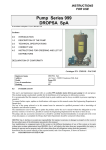
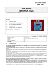
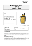
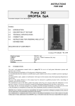
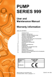
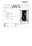
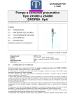
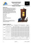
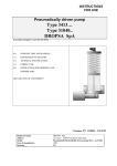
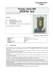
INSTRUCTIONS
FOR USE
Motor-driven gear pumps
In accordance with point 1.7.4, to I, Dir 98/37 CE
SERIES
341----3400000
Sections:
0.0
INTRODUCTION
1.0
DESCRIPTION OF THE PUMP
2.0
TECHNICAL SPECIFICATIONS
3.0
CORRECT USE
4.0
INSTRUCTIONS FOR ORDERING
AND LIST OF DISTRIBUTORS
DECLARATION OF CONFORMITY
Catalogue P/N C2010IE - Wk 23/02
Registered name
Address
Model
Year of manufacture
Marking
0.0
DROPSA SpA
via Croce 1, 20090 Vimodrone (MI), Italy
Motor-driven gear pump 3410--1999
CE
INTRODUCTION
This user’s and maintenance manual refers to motor-driven gear pumps, for use in mineral oil lubrication systems.
It is recommended that this manual is carefully kept in good condition and is always available to persons requiring to
consult it.
To request further copies, updates or clarifications with respect to this manual contact the Engineering Department at
Dropsa SpA.
The use of the pump referred to in this manual must be entrusted to qualified personnel with a knowledge of
hydraulics and electrical systems.
The manufacturer reserves the right to update the product and/or the user’s manual without the obligation to revise
previous versions. It is however, possible to contact the Engineering Department for the latest revision in use.
The pump, and any accessories mounted on it, should be carefully checked immediately on receipt and in the event
of any discrepancy or complaint the Dropsa SpA Sales Department should be contacted without delay.
DROPSA S.p.A. declines to accept any responsibility for injuries to persons or damage to property in the event of
the non-observance of the information presented in this manual.
Any modification to component parts of the system or the different destination of use of this system or its parts
without prior written authorisation from DROPSA S.p.A. will absolve the latter from any responsibility for injury or
damage to persons and/or property and will release them from all obligations arising from the guarantee.
Instructions for the correct ordering of the required model, and a list of importers, is shown in Section 4.
1.0
DESCRIPTION OF THE PUMPS
These new pump units have been designed as the result of over thirty years experience in the field of developing and
manufacturing gear pumps.
The application possibilities are numerous; the pumps are self-lubricating and are able to operate with oils or any
other fluid with proven lubricating capacity.
These pumps can therefore be utilised in the fields of lubrication, refrigeration, hydraulics and, more generally, for
the circulation of fluids for machines, motors and linear motion applications; these units can also be employed on
recirculating systems without the need for particularly fine filtering of the circulation fluid.
One of the most striking features of these pumps is the high degree of silentness in operation, obtained with the
use of gears specially designed for this type of unit.
Also, thanks to particularly precise machining and finishing, a significant improvement has been achieved in
efficiencies compared to all previous similar models produced.
To ensure an external seal the pumps have an “O” ring located between the pump body and the relative cover in
addition to a lip seal on the main shaft.
The body of the pump is produced in hydraulic cast iron and the gears and relative shafts in chrome-nickel steel –
carburized, hardened and ground.
The body of the low flow rate pump (up to 500 cc/min) is made of sintered steel; the shafts and gears in carburized
and hardened steel with a seal on the main shaft.
WARNING
For all the motor-driven pumps we have shown the applied power to the motors in function of the maximum
pressure demand indicated in the table. For higher pressures the motor must be suitably sized; accordingly, to obtain
a quotation, state the voltage, the maximum operating pressure and if the service will be continuous or intermittent.
(Max pressure = 30 bar for continuous service); (max. pressure = 60 bar for intermittent service). Working
temperature of the fluid –20 - +100 degrees with low to medium velocity oil.
On request flameproof motors can be supplied in various voltages.
Request availability from Dropsa SpA.
1.1
Gear pumps for low flow rates with pressures of 30-80 bar.
Gear pumps for low flow rates can also be supplied assembled to the motors.
3 sizes are available: 0.35 – 0.5 – 1.2 litres/min. at 1500 rpm.
The direction of rotation is indifferent; simply invert the suction and delivery tubes.
The service can be either continuous or intermittent.
The following standard power supplies are provided for:
• 220/380 V – 50 Hz
• 240/440 V – 60 Hz
• 415V
_ 50 Hz
Other voltages and frequencies are available on request.
The motors have IP55 grade protection.
In addition, it is possible to order separately a suction filter c/w dip tube (400 mesh/cm2, filtering grade 260) of an
overall length of between 100 and 455 mm depending on the needs of different installations.
These gear pumps are suitable for operating with oils of a viscosity between 150 and 1000 cSt at fluid working
temperatures in the range of –20 - +100 °C.
The maximum useful pressure in intermittent service is 80 bar; for this the design rotation speed of the pump is 1500
or 3000 rpm.
C2010IE - Motor-driven pump 31040--
Rev. 1
Jun. ‘02
Page 2 of 10
Assembly Part N°
Pump for
external
3099127
3099004
3099131
Pump in tank
Flow rate in
litres/min
a 1500 rpm
3099129
3099130
3099133
0.35
0.5
1.2
38
40
47
SUCTION
1.2
DELIVERY
Accessories
♦ Pressure switch
DESCRIPTION
bar
1-10
10-20
20-50
Part N°
NO
3291028
3291034
3291022
NC
3291031
3291035
3291021
♦ Control panel
DESCRIPTION
Part N°
It is also possible to supply, as an accessory to the pump, a control panel Single phase : 1639077 (plastic)
called a “VIP”, which permits the controlling of the various operating
1639081 (sheet metal)
parameters: pressure switch and level alarms, work and pause cycles.
3-phase: 1639087
1639089
•
Suction filter assembly
Part N° 3088053 length 165 mm
Part N°3088054 length 80 mm
Part N°3088055 length 415 mm
Part N°3088056 length 130 mm
2.0
TECHNICAL SPECIFICATIONS
2.1
Electrical diagram
2.2
Hydraulic diagram
C2010IE - Motor-driven pump 31040--
Rev. 1
Jun. ‘02
Page 3 of 10
3.0
CORRECT USE
3.1
Putting into service
Damage to the power supply cable and housing could result in contact with high voltage live parts and hence be a
danger to life:
♦ carefully check the integrity of the power supply cable and the unit before use;
♦ In the event of there being damage to the power supply cable or the unit, DO NOT put the system into service!;
♦ Replace the damaged power supply cable with a new one;
♦ The unit can be opened and repaired ONLY by qualified personnel;
♦ In order to prevent dangers of electric shock due to direct or indirect contact with live parts it is necessary that
the electrical power supply line is adequately protected by a suitable differential magneto-thermal circuit breaker
with an intervention threshold of 0.03 Ampere and a max. operating time of 1 second.
The breaking capacity of the circuit breaker must be ≤ 10 kA and the nominal current In = 6 A.
♦ The pump MUST NOT be submersed in fluids or utilised in environments which are particularly aggressive or
explosive/inflammable if not prepared for this purpose beforehand by the supplier.
♦ For correct fixing verify the distance between centres shown in the diagram in Figure ?
♦ Use gloves and safety glasses as required in the lubrication oil safety chart;
♦ DO NOT use aggressive lubricants with NBR gaskets and seals; if in doubt consult the Engineering Department
of Dropsa SpA, who will provide a chart with the details of recommended oils;
♦ DO NOT ignore dangers to health and observe all hygiene standards;
♦ WARNING! All electrical components must be grounded. This refers to both electrical components and control
devices. In this regard ensure that the ground cable is correctly connected. For reasons of safety the ground cable
must be approx. 100 mm longer than the phase cables. In the event of accidental detachment of the cable, the
ground terminal must be the last to be removed.
Action to be taken prior to start up
♦ Verify the integrity of the pump;
♦ Fill the tank with suitable lubricant (min/max indication on the tank);
♦ Verify that the pump is at operating temperature and the tubing free from air bubbles;
♦ Check that the electrical connections have been effected correctly (CEI 64/8, IEC 364);
♦ Verify the correct connections of the level and any pressure switch to the control panel
♦ On starting the pump, check that the direction of rotation of the electric motor: if rotating in the wrong
direction invert the cable connections.
3.2
Use
1.
2.
3.
4.
3.3
verify the settings made;
press the start button of the machine to which the pump is connected;
verify the starting of the pump;
verify the adequate lubrication of the machine (if doubt exists as to the correct functioning consult the
Engineering Department of Dropsa SpA to request test procedures).
Transport and storage
Transport and storage is effected in a cardboard package.
No particular precautions are required except as noted on the package itself.
handling can be effected by one person.
!
Lift the unit with taking account of the right way up indicated on the cardboard carton
!
The machine components can withstand temperatures, during storage, from -20 to +50°C; however, in
order to avoid damage, starting of the machine should occur at a minimum temperature of -5°C.
C2010IE - Motor-driven pump 31040--
Rev. 1
Jun. ‘02
Page 4 of 10
3.4
Assembly/Disassembly
No pump assembly operations are envisaged.
For wall mounting ensure adequate space is available (as shown in the installation diagram) to avoid abnormal
postures and possible impacts; four fixing holes are provided with different characteristics depending on the version.
Subsequently it will be necessary, as previously described, to connect the pump to the machine hydraulically and
then to connect the control panel.
During the disassembly phase ensure the tank is empty.
Disconnect the electrical and hydraulic parts.
Where the machine is to be scrapped, do not dispose of potentially polluting parts in the environment, following
local regulations for their correct disposal.
At the time of the machine being scrapped it is necessary to remove and destroy the identification plate and all other
relative documents.
3.5
Regulation
The only parameter which can be modified is the pressure.
3.6
Maintenance
!
Locate the machine in conditions which facilitate easy access.
Utilise individual protection to avoid contact with mineral oil or grease.
Periodically it is necessary to check:
VERIFICATION
The state of lubrication
The oil level
Cleanliness of the filling and intake filter
Clean the tank of any deposits on the bottom
WORK CYCLE
1000
2000
4000
6000
The machine does not require any special tools to carry out checks or maintenance tasks, However, it is
recommended that only tools suitable for the tasks and in good condition should be utilised (DPR 547/55) to avoid
injury to persons or damage to machine parts.
3.7
Repairs
The following diagnostic table indicates the main anomalies which may be encountered, the probable causes and
possible solutions.
The anomalies shown are:
• the pump fails to deliver sufficient oil or no oil at all
• the pump fails to deliver oil at the prescribed pressure
• failure to effect lubrication cycle
In case of doubts and/or problems which cannot be resolved do not attempt to disassemble parts of the machine but
contact the Engineering Department of DROPSA S.p.A.
C2010IE - Motor-driven pump 31040--
Rev. 1
Jun. ‘02
Page 5 of 10
DIAGNOSTIC TABLE
PROBABLE CAUSE
INDICATION
The pump does not deliver oil or
does not deliver oil in the exact
quantity prescribed
•
Drawing in air due to the tank
being empty
The intake filter is dirty or
blocked
•
The internal connections are
loose
Pump has deteriorated
Pressure regulating valve loose,
so the oil returns immediately to
the tank before flowing through
the delivery valve
Release valve damaged
•
•
Replace the valve
•
Incorrect setting of the
regulating valve
•
•
Presence of dirt under the bypass valve
To the pump outlet connect a
tube approximately 30cm long
with a manometer connected to
the free end. Regulate the valve
by means of turning the screw
and reading the corresponding
pressure value on the
manometer
Disassemble the valve and clean
or replace it as necessary
•
•
•
•
•
The pump does not deliver oil at
the prescribed pressure
3.8
REMEDY
•
•
•
•
Refill the tank and purge air
from the system
Wash the filter in petrol and
blow it through with
compressed air
Tighten all connections ensuring
there are no leakages
Replace the pump
Tighten the regulating screw
until oil exits from the delivery
Dangers present in use
The verification of conformity with the essential safety requirements and regulations of the Machine Directive is
effected by means of the compilation of a check list which has been pre-prepared and is contained in the technical
file.
The lists which are utilised are of three types:
•
list of dangers (as in EN 414 referring to EN 292)
•
application of essential safety requirements (Machine Dir. - att. 1, part 1)
•
electrical safety requirements (EN 60204-1)
The following is a list of dangers which have not been fully eliminated but which are considered acceptable:
♦
it is possible to encounter squirts of oil (for this reason appropriate protective clothing must be worn)
♦
contact with oil -> see the requirements for the use of suitable personal protective clothing
♦
use of unsuitable lubricant -> the characteristics of the fluid are shown on the pump and in the manual
(in case of doubt contact the Eng. Dept of Dropsa Spa)
♦
protection against direct and indirect contact must be provided by the user
♦
given the purpose of the pump it must always be functioning; for this reason it is necessary to pay
attention to the electrical connections which, in the case of a power failure, the customer’s machine is
restarted only by means of a reset, while the lubrication pump is able to restart.
INADMISSIBLE FLUIDS
Fluid
Lubricants with abrasive additives
Lubricants with silicone based additives
Petrol – solvents – inflammable liquids
Corrosive products
Water
C2010IE - Motor-driven pump 31040--
Danger
High wear rate of contacted parts
Seizure of the pump
Fire – explosion – damage to seals
Corrosion of the pump– injury to persons
Oxidation of the pump
Rev. 1
Jun. ‘02
Page 6 of 10
Food substances
C2010IE - Motor-driven pump 31040--
Contamination of the substances themselves
Rev. 1
Jun. ‘02
Page 7 of 10
Gear pumps for low flow rates with pressures of 30-80 bar
Assembly
Part N°
Motor power
Flow rate
litres/min
3405000
size
56
kW
0.09
rpm
1500
0.50
3406000
3407000
3402002
3402006
3405079
3407003
63
63
56
56
56
63
0.25
0.185
0.09
0.09
0.09
0.185
3000
1500
1500
1800
1500
1800
1.00
0.50
0.35
0.41
0.50
0.41
Weight
Kg
3.7
A
171
B
137
C
104
D
56
E
80
5.5
5.5
3.7
3.7
3.7
5.5
194
194
171
171
171
194
153
153
137
137
137
153
119
119
104
104
104
119
56
56
54
54
56
54
90
90
80
80
80
90
Dimensions in mm
F
G
H
L
65
56
5.5
71
75
75
65
65
65
75
58
58
56
56
56
58
5.5
5.5
5.5
5.5
5.5
5.5
--71
71
---
M
90
N
6
P
106
R
36
--90
90
---
--6
6
---
--106
106
---
--36
36
---
This assembly consists only of the motor and the gear pump.
Intermit
tent
Electric motor for
continuous operation
DropsA
Line
By-pass
setting
Standard
setting
01
2-20 bar
5 bar
26
25-80 bar
70 bar
04-06
25-80 bar
50 bar
By-pass
with
nonreturn
valve
with
release
valve
Assembly
3404023
3404022
3404026
3404046
3405099
3405101
3405121
3415122
3405098
3405100
3405123
3405124
Size
56
56
56
56
56
56
56
56
56
56
56
56
Motor power
Voltage
Flow rate
litres/min
kW
0.09
0.09
0.06
0.06
0.09
0.09
0.06
0.06
0.12
0.12
0.06
0.06
220/380V-50 Hz
220/380V-50 Hz
110 V – 50 Hz
110 V – 50 Hz
220/380V – 50 Hz
220/380V– 50 Hz
110 V – 50 Hz
110V – 50 Hz
220/380V-50 Hz
220/380V-50 Hz
110 V – 50 Hz
110 V – 50 Hz
0.35
0.50
0.35
0.50
0.35
0.50
0.35
0.50
0.35
0.50
0.35
0.50
rpm
1500
1500
1500
1500
1500
1500
1500
1500
1500
1500
1500
1500
Dimensions
*A
205
205
205
205
205
205
205
205
187
187
205
205
*B
156
156
156
156
156
156
156
156
156
156
156
156
*C
110
110
110
110
110
110
110
110
110
110
110
110
D
38
40
38
40
38
40
38
40
38
40
38
40
This assembly is composed of a gear pump, an electric motor, a manometer and a valve block.
Thanks to a by-pass it is possible to regulate the working pressure in accordance with the requirements of the system to which the pump is
connected.
Also included in the valve block is a non-return valve or alternatively a release valve so that it can be adapted for use with the different
DROPSA systems (line 01, line 26, lines 04-06) or on other systems of a similar nature.
It is also possible to order separately an intake filter with a dip tube (400 mesh/cm2 filtering grade 260) of an overall length variable between
100 and 455 mm depending on the differing requirements of the installation).
THE MOTOR VOLTAGE MUST ALWAYS BE STATED AT THE TIME OF ORDERING.
Pressure regulating screw
SUCTION
Vertical or horizontal application motor-driven pumps–
motor type B5 4 pole – Pressure 30/60 bar
WITHOUT BY-PASS
Assembly
Part N°
3410110
3410112
3410114
341016
3410118
3410120
3410122
3410124
3410126
3410128
3410130
3410132
3410134
3410136
3410138
3410140
litres
2
3.5
5.5
5.5
10
10
19
19
26
26
32
32
45
45
60
60
Power
kW
0.185
0.25
0.25
0.55
0.25
0.55
0.55
0.75
0.75
1.1
0.75
1.1
1.1
2.2
2.2
30
Press.
max
bar
Wt
Kg
26
20
13
29
7
15
8
11
8
12
6
10
7
15
11
15
8.6
8.6
10.4
12.9
10.4
12.9
15.7
17.2
19.5
25
19.5
25
28.5
48.5
51.5
54.7
“gas
D
1/4
1/4
3/8
3/8
3/8
3/8
1/2
1/2
3/4
3/4
3/4
3/4
1
1
1
1
E
G
H
K
I
L
Dimensions in mm
M
N
O
115
130
130
165
130
165
165
165
165
165
165
165
165
215
215
215
148
167
167
187
167
187
187
187
187
210
187
210
212
236
236
236
306
333
355
392
355
392
437
437
451
473
451
473
494.5
570
570
570
118
126
148
159
148
159
202
202
214
214
214
214
239.5
248.5
248.5
248.5
---------------------------------
9
9
9
11
9
11
11
11
11
11
11
11
11
13
13
13
95
110
110
130
110
130
140
140
150
150
150
150
155
170
170
170
11
129
129
149
129
149
149
149
149
172
149
172
172
196
196
196
32
32
42
42
42
42
53
53
59
159
59
59
65.5
65.5
65.5
65.5
P
Q
R
T
U
V
63
63
85
85
85
85
102
102
113
113
113
113
138.5
138.5
138.5
138.5
8.7
8.7
12.3
12.3
12.3
12.3
15.2
15.2
18.9
18.9
18.9
18.9
22.5
22.5
22.5
22.5
60
60
80
80
80
80
90
90
108
108
108
108
130
130
130
130
---------------------------------
140
160
160
200
160
200
200
200
200
200
200
200
200
250
250
250
23
23
23
28
23
28
28
28
28
28
28
28
28
33
33
33
TANK DRILLING
NON-STANDARD DIMENSIONS
SUCTION
DELIVERY
THE MOTOR VOLTAGE MUST ALWAYS BE STATED AT THE TIME OF ORDERING.
C2010IE - Motor-driven pump 31040--
Rev. 1
Jun. 02’
Page 10 of 13
WITH BY-PASS
Assembly
Part N°
3410111
3410113
3410115
3410117
3410119
3410121
3410123
3410125
3410127
3410129
3410131
3410133
3410135
3410137
3410139
3410141
litres
2
3.5
5.5
5.5
10
10
19
19
26
26
32
32
45
45
60
60
Power
kW
Press.
max
bar
Wt
Kg
26
20
13
29
7
15
8
11
8
12
6
10
7
15
11
15
8.7
8.7
10.6
13.1
10.6
13.1
16
17.5
20
25.5
20
25.5
29
49
52
55.2
0.185
0.25
0.25
0.55
0.25
0.55
0.55
0.75
0.75
1.1
0.75
1.1
1.1
2.2
2.2
3
“gas
D
1/4
1/4
3/8
3/8
3/8
3/8
1/2
1/2
3/4
3/4
3/4
3/4
1
1
1
1
E
G
H
K
I
L
115
130
130
165
130
165
165
165
165
165
165
165
165
215
215
215
148
167
167
187
167
187
187
187
187
210
187
210
212
236
236
236
---------------------------------
118
128
148
159
148
159
204
204
218
218
218
218
238.5
248.5
248.5
248.5
306
333
355
392
355
392
439
439
455
477
455
477
494.5
570
570
570
9
9
9
11
9
11
11
11
11
11
11
11
11
13
13
13
Dimensions in mm
M
N
O
P
95
110
110
130
110
130
140
140
150
150
150
150
155
170
170
170
111
129
129
149
129
149
149
149
149
172
149
172
172
196
196
196
32
32
42
42
42
42
53
53
59
59
59
59
65.5
65.5
65.5
65.5
63
63
85
85
85
85
104
104
117
117
117
117
138.5
138.5
138.5
138.5
Q
R
T
U
V
8.7
8.7
12.3
12.3
12.3
12.3
15.2
15.2
18.9
18.9
18.9
18.9
22.5
22.5
22.5
22.5
60
60
80
80
80
80
90
90
108
108
108
108
130
130
130
130
58
58
78
78
78
78
86
86
102.5
102.5
102.5
102.5
113
113
113
113
140
160
160
200
160
200
200
200
200
200
200
200
200
250
250
250
23
23
23
28
23
28
28
28
28
28
28
28
28
33
33
33
Vertical or horizontal application motor-driven pumps–
motor type B3/B14 4 pole – Pressure 30/60 bar
WITHOUT BY-PASS
Assembly
Part N°
3410011
3410012
3410027
3410013
3410028
3410014
3410029
3410015
3410030
3410016
3410031
3410017
3410032
3410018
3410066
3410068
litres
2
3.5
5.5
5.5
10
10
19
19
26
26
32
32
45
45
60
60
Power
kW
0.185
0.25
0.25
0.55
0.25
0.55
0.55
0.75
0.75
1.1
0.75
1.1
1.1
2.2
2.2
3
Press.
max
bar
Wt
Kg
26
20
13
29
7
15
8
11
8
12
6
10
7
15
11
15
8.6
8.6
10.4
12.9
10.4
12.9
15.7
17.2
19.5
25
19.5
25
28.5
48.5
51.5
54.7
“gas
D
1/4
1/4
3/8
3/8
3/8
3/8
1/2
1/2
3/4
3/4
3/4
3/4
1
1
1
1
E
F
G
H
K
I
Y
Dimensions in mm
L
M
N
O
80
90
90
100
90
100
100
100
100
100
100
100
100
140
140
140
127
140
150
166
150
166
203
203
210
216
210
216
222.5
238.5
238.5
238.5
155
173
173
192
173
192
192
192
192
216
192
216
216
238
238
238
306
333
355
392
355
392
437
437
451
473
451
473
494.5
570
570
570
118
126
148
159
148
159
204
204
218
218
218
218
239.5
248.5
248.5
248.5
-
63
71
71
80
71
80
80
80
80
90
80
90
90
100
100
100
7
7
7
9
7
9
9
9
9
9
9
9
9
12
12
12
SUCTION
8
9
9
10
9
10
10
10
10
11
10
11
11
12
12
12
111
129
129
149
129
149
149
149
149
172
149
172
172
196
196
196
32
32
42
42
42
42
53
53
59
59
59
59
65.5
65.5
65.5
65.5
P
Q
R
S
T
U
V
63
63
85
85
85
85
102
102
113
113
113
113
138.5
138.5
138.5
138.5
8.7
8.7
12.3
12.3
12.3
12.3
15.2
15.2
18.9
18.9
18.9
18.9
22.5
22.5
22.5
22.5
60
60
80
80
80
80
98
98
116
116
116
140
140
140
160
160
100
112
112
125
112
125
125
125
125
140
125
140
140
160
160
160
-
120
136
136
155
136
155
155
155
155
174
155
174
174
196
196
196
100
110
110
125
110
125
125
125
125
128
125
128
128
170
170
170
VIEW FROM X
DELIVERY
NON-STANDARD DIMENSIONS
THE MOTOR VOLTAGE MUST ALWAYS BE STATED AT THE TIME OF ORDERING.
C2010IE - Motor-driven pump 31040--
Rev. 1
Jun. 02’
Page 11 of 13
WITH BY-PASS
Assembly
Part N°
3410019
3410020
3410033
3410021
3410034
3410022
3410035
3410023
3410036
3410024
3410037
3410025
3410038
3410026
3410067
3410069
litres
2
3.5
5.5
5.5
10
10
19
19
26
26
32
32
45
45
60
60
Power
kW
0.185
0.25
0.25
0.55
0.25
0.55
0.55
0.75
0.75
1.1
0.75
1.1
1.1
2.2
2.2
3
Pres.
max
bar
Wt
Kg
26
20
13
29
7
15
8
11
8
12
6
10
7
15
11
15
8.7
8.7
10.6
13.1
10.6
13.1
16
17.5
20
25.5
20
25.5
29
49
52
55.2
“gas
D
1/4
1/4
3/8
3/8
3/8
3/8
1/2
1/2
3/4
3/4
3/4
3/4
1
1
1
1
Dimensions in mm
M
N
O
E
F
G
H
K
I
Y
L
80
90
90
100
90
100
100
100
100
100
100
100
100
140
140
140
127
140
150
166
150
166
203
203
210
216
210
216
222.5
238.5
238.5
238.5
155
173
173
192
173
192
192
192
192
216
192
216
216
238
238
238
-
118
126
148
159
148
159
206
206
222
222
222
222
239.5
248.5
248.5
248.5
306
333
355
392
355
392
439
439
455
477
455
477
494.5
570
570
570
63
71
71
80
71
80
80
80
80
90
80
90
90
100
100
100
7
7
7
9
7
9
9
9
9
9
9
9
9
12
12
12
C2010IE - Motor-driven pump 31040--
Rev. 1
8
9
9
10
9
10
10
10
10
11
10
11
11
12
12
12
Jun. 02’
111
129
129
149
129
149
149
149
149
172
149
172
172
196
196
196
32
32
42
42
42
42
53
53
59
59
59
59
65.5
65.5
65.5
65.5
P
Q
R
S
T
U
V
63
63
85
85
85
85
104
104
117
117
117
117
138.5
138.5
138.5
138.5
8.7
8.7
12.3
12.3
12.3
12.3
15.2
15.2
18.9
18.9
18.9
18.9
22.5
22.5
22.5
22.5
60
60
80
80
80
80
98
98
116
116
116
116
140
140
140
140
100
112
112
125
112
125
125
125
125
140
125
140
140
160
160
160
58
58
78
78
78
78
86
86
102.5
102.5
102.5
102.5
113
113
113
113
120
136
136
155
136
155
155
155
155
174
155
174
174
196
196
196
100
110
110
125
110
125
125
125
125
128
125
128
128
170
170
170
Page 12 of 13
CE Declaration Of Conformity
Manufacturer:
DROPSA SpA
Company
Via Croce, 1 - 20090 Vimodrone (MI), Italy
Address
+39 02 250791
Telephone
It is certified that:
The machine:
Motor-driven gear pump type 3410---
∗
is manufactured in conformity with the DIRECTIVE OF THE COUNCIL OF THE EUROPEAN COMMUNITY concerning the harmonisation of member states
legislation relative to machines (98/37 CE + 91/368/CEE), EMC (89/336/CEE) and BT (73/23/CEE) and relative amendments.
∗
is manufactured in accordance with the following standards and harmonised technical specifications:
EN 292/1, EN 292/2, EN 50081-2, EN 50082-2, CEI EN 60204-1, EN 1050.
Technical Manager
Product Manager
Ing. Walter Divisi
Name
DROPSA SpA - Vimodrone (MI) - Italy
Company
January 1999
Date
Signature
DROPSA SPA DISTRIBUTORS
ITALY
Dropsa SpA
t.(+39) 02-250791
f.(+39) 02-25079767
U.S.A.
Dropsa Corporation
t.(+1) 586-566-1540
f.(+1) 586-566-1541
BRAZIL
Dropsa
t.(+55) 011-563-10007
f.(+55) 011-563-19408
AUSTRALIA
Dropsa Australia Ltd.
t.(+61) 02-9938-6644
f.(+61) 02-9938-6611
SPAIN
Polydrop, S.A.
t.(+34) 93-260-22-50
f.(+34) 93-260-22-51
U.K.
Dropsa (UK) Ltd
t.(+44) 01784-431177
f.(+44) 01784-438598
GERMANY
Dropsa Gmbh
t.(+49) 0211-394-011
f.(+49) 0211-394-013
FRANCE
Dropsa Ame
t.(+33) 01-3993-0033
f.(+33) 01-3986-2636