1
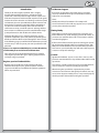
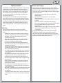
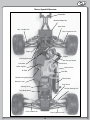
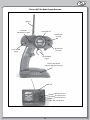
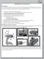
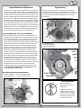
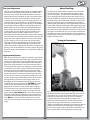
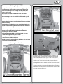
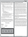
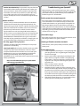
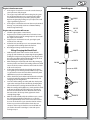
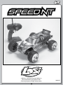
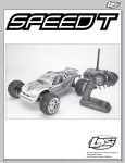
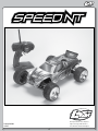
Not responsible for errors. All prices
subject to change without notice.
Printed 06/09
16265
Losi, a Division of Horizon Hobby, Inc.
1
Introduction
Losi/Horizon Support
If you have any questions concerning setup or operation
of your Speed-NT RC vehicle please call Horizon Customer
Support at 1-877-504-0233.
Thank you for choosing the Speed-NT. This is a highly
developed RC model that features a sophisticated radio
system and a nitro fuel powered engine. It does require some
mechanical experience and direct adult supervision. This guide
contains the basic instructions and drawings needed to operate
and maintain your new Speed-NT. Please take the time to read
through these instructions completely before attempting to
run your new model. Your hobby dealer cannot under any
circumstances accept a model for return or exchange that has
been run. We are confident you will be satisfied with the highspeed performance in this durable and resilient vehicle.
Hours:
Monday thru Friday from 8:00am CST to 5:00pm CST
You are welcome to call us with any support issue, or question
you may have about the Speed-NT.
Getting Ready
Thoroughly read all the enclosed material, precautions and
follow instructions to avoid damaging your new RC vehicle. If
you choose to not follow these steps or instructions, it will be
considered negligence.
Understanding that you are anxiously wanting to get your
Speed-NT ready for the open road, it will be to your long term
benefit to make the effort and read through the entire manual.
In the following pages you will find all the information you will
need to set up as well as operate your new Speed-NT to its full
potential.
If after review of this manual and prior to running your SpeedNT, you determine this RC vehicle is not what you want—DO
NOT proceed and DO NOT run the Speed-NT. If the Speed-NT
has been run, your local hobby shop will not be able to process
a return or accept it for exchange.
If you are an experienced RC hobbyist, or new to RC vehicles,
it will benefit you to read all enclosed information.
From everyone at Losi we would like to thank you again for
choosing the Speed-NT. Our goal is helping people have fun
and enjoy using our products.
Caution:
Age Recommendation: 14 years or over. This is not a toy. This
product is not intended for use by children without direct adult
supervision.
Register your Losi Product Online
Register your Speed-NT now and be the first to find out
about the latest options parts, product updates and more.
Log on to www.LOSI.com and follow the product registration
link to stay connected.
This vehicle is capable of extreme speed and careful attention
and care must be used when operating the Speed-NT.
When driving the Speed-NT it is important that you take
measures to avoid someone being hit by the vehicle. You may
cause serious injury to another person, or to personal property
should you make contact while running the Speed-NT.
2
Safety Precautions:
Batteries and Charging:
The Speed-NT uses rechargeable batteries such as NiMH or
LiPo. These batteries all have special requirements to preserve
performance and last a long time. Read all instructions and
precautions that are provided with the batteries intended to be
used in the Speed-NT.
•
Read all instructions provided by the manufacturer
of the batteries.
•
Responsible adult supervision is necessary while
charging batteries.
•
Always check to ensure the polarity of battery connection
is correct.
•
Never leave batteries unattended while charging.
•
Never charge a battery while it is installed in the Speed-NT.
•
Do not charge any battery that appears to have
any damage.
•
If there are exposed wires do not charge or use the battery
until you have installed shrink-wrap or replaced the
complete wire.
If charging NiMH batteries, select a charger to meet your
requirements. Chargers can be of two primary types for
their source of power; a 100-240V wall charger, or one which
requires a 12V power supply. Follow the charger manufacturer’s
instructions and precautions during each use.
THIS PRODUCT IS NOT A TOY! The Speed-NT is a sophisticated,
high-performance radio control model which needs to be
operated with caution and common sense. Failure to operate
this model in a safe and responsible manner could result in
personal and/or property damage. It is your responsibility
to see that the instructions and warnings are followed and
precautions adhered to.
The Speed-NT is not intended for use by children without
direct adult supervision. Losi and Horizon Hobby shall not be
liable for any loss or damages, whether direct, indirect, special,
incidental, or consequential arising from the use, misuse, or
abuse of this product or any product required to operate it.
*This is still only a model – do not expect it to do unrealistic
stunts.
Warnings:
The Speed-NT is powered by a special fuel containing
flammable liquids and special care must be taken as noted
below.
•
Model fuel is dangerous if handled carelessly. Follow all
directions and precautions on the fuel container. NEVER
drink fuel - call a doctor immediately if ingested or
splashed into your eyes.
•
Keep fuel and all chemicals out of the reach of children.
•
Always keep the fuel container closed and never use
around an open flame or while smoking.
•
The exhaust emits poisonous carbon monoxide fumes.
Always run your model in a well ventilated area and never
attempt to run it indoors.
•
The top of the engine and the exhaust pipe are extremely
hot during and after use. Use caution not to touch these
parts, especially when refueling.
•
The engine can be loud especially when run in a confined
area. If you find the noise objectionable make sure to use
ear protection.
•
This model is controlled by a radio signal that is subject
to interference from sources outside your control.
Interference can cause temporary loss of control so it is
advised to always keep a safety margin in all directions to
avoid collisions.
•
Always operate your model in an open area away from
people and cars. The potential speed of this model can
cause injury or damage.
•
Never operate your Speed-NT with low transmitter or
receiver batteries – especially AA dry cells as control and
power will be limited.
•
Repeated or prolonged use of heavy braking will cause the
brakes to overheat and fail! Always leave plenty of room
for stopping.
•
It will take as much room to stop as it does to accelerate to
speed. Always run in an open area with plenty of braking
room.
3
Supplied and Required Equipment
Required Equipment:
Supplied tools:
You will need the following items to start and run the Speed-NT.
20% Sport Fuel – Preferably Nitrotane 20% Sport (LOSF0020).
Fuel Bottle – LOSB5201 or similar.
Glow Igniter – Losi aluminum rechargeable unit with charger
(LOSB5221) or similar.
7.2V rechargeable battery for the Spin-Start – LOSB9900 or
similar
Charger for 7.2V battery and receiver pack (optional) LOSB9606
or similar.
Coming Soon: LOSA99072 Deluxe Nitro Starter Kit with
everything except fuel at a great package price.
2-Way wrench
Radio Adjusting Screwdriver
Transmitter / Receiver BIND Plug
Four (4) Hex Wrench “L” shaped
.050-inch, 1/16-inch, 5/64-inch, and 3/32-inch
Flat Turnbuckle Wrench
Recommended Accessories:
Small flat blade and Phillips screwdrivers (LOSA99167) or:
Flat blade screwdriver with infrared temperature gauge
(LOSA99171)
Needle-nose pliers
Quality .050-inch, 1/16-inch, 5/64-inch, 3/32-inch and 1.5mm
hex (Allen) drivers
Losi® Nitrotane™ 20% Sport fuel(LOSF0020 or LOSF0120)
Other fuels may not support the engine warranty.
Fuel bottle (LOSB5201)
Glow Igniter (LOSB5221)
Rechargeable Receiver battery (LOSB9951)
4
The Losi Speed-NT Overview
Wheelie Bar
Receiver Battery Box
Rear Shock
Rear Camber Link
Rear Suspension Arm
Slipper
Engine
Rear Body Mount
Exhaust Header
Fuel Line
Carburetor
Brake Adjuster
Pressure Line
Air Filter
Fuel Filler
Throttle Linkage/Adjuster
Exhaust Pipe
Receiver Cover
Front Shock
Steering Servo
Tie Rod/Steering Link
Front Body Mount
Front Camber Link
Front Suspension Arm
5
The Losi MTX Pro Radio System Overview
Antenna
Dual Rate
Adjustment (ST. D/R)
Steering Wheel
Steering Trim
(ST. Trim)
Throttle Trim
(TH. Trim)
Power On/Off
Switch
Throttle/Brake
Trigger
Steering and Throttle
Endpoint Adjustment Pots (4)
Bind LED
Auxiliary Channel
Throttle Channel
Steering Channel
Binding Port
6
Speed-NT Electronics System Overview
About the Radio
The Losi DSM radio installed in the Speed-NT is a state of the art system featuring the latest technology that requires no crystals. This
system includes all the features you may find useful. Be sure to read through the Radio operation instructions on what and how to use
these features. The following is a simple guide to items and functions commonly referred to.
1.
2.
3.
4.
5.
6.
7.
Steering Wheel - Controls the trucks direction (left/right).
Throttle Trigger – Controls the speed and braking (pull for throttle and push forward for brakes).
Throttle Trim (TH.TRIM) - Allows you to set the idle/brake of the truck.
Steering Trim (ST.TRIM) – Adjusts the “hands off” direction of the truck.
Transmitter Antenna - Transmits signal to the receiver in the truck.
Servo Reversing Switches – Changes the direction of servo operation.
Power & Signal Indicators (LEDs)
Red (left) indicates signal strength.
Green (right) indicates battery power.
8. Power Switch - Turns your transmitter ON and OFF.
9. Steering Rate (ST.D/R) – Adjusts how much the wheels turn when steering wheel is turned right/left.
10. Endpoint Adjustment Pots – allow you to adjust the maximum movement of the servos.
11. Bottom Cover – Removable for installing AA batteries.
12. Binding LED – Blinks when binding—solid indicates binding complete.
Re-Binding the Transmitter to the Receiver
The Losi DSM® radio system included in the Speed-NT operates on 2.4GHz and provides 79 different channels, which are automatically
AntennaThe communication between the transmitter
selected when the transmitter and vehicle are turned on.
Dual Rate 6
Adjustment (ST. D/R)
Steering Wheel
Steering Trim
(ST. Trim)
12
5
6
Throttle Trim
(TH. Trim)
Power On/Off
Switch
9
4
Throttle/Brake
Trigger
7
Steering and Throttle
Endpoint Adjustment Pots (4)
8
3
1
2
Bind LED
Auxiliary Channel
Throttle Channel
Steering Channel
Binding Port
10
11
11
and receiver begins in the few seconds after the transmitter and vehicle are both turned on. This is called the binding process. The Losi
DSM radio system will not interfere with previous technology radio systems that operate on 27MHz or 75MHz frequencies, and you
will not receive any interference from them. Although set at the factory, below are the steps required to re-bind your transmitter to the
receiver should the need arise. During the binding process there is a unique ID from the transmitter communicated to the receiver to
ensure trouble-free radio operation.
7
Binding the Radio System
Using the EPA Adjustment
The Endpoint Adjustment (EPA) feature of the Losi DSM radio
allows you to set the amount the servo travels when you turn
the steering wheel or push/pull the throttle. This is especially
helpful to prevent the servos from stalling with normal
operation.
Steering:First set the steering trim so the truck goes
straight without touching the steering wheel. Lift
the front of the truck off of the ground and turn
the steering wheel to the right. Use the included
mini screwdriver to adjust the pot marked “right”
back and forth stopping when the wheels can
turn to the right no more. Repeat this procedure
turning left using the pot marked “left”.
Throttle:First set your Throttle/Brake trim. With the engine
not running, remove the air cleaner. Pull full back
on the throttle trigger and note the position of
the carburetor barrel. Adjust the pot marked
“throttle” back and forth so that the barrel just
reaches wide open (going further will only hurt
performance).
Brake:Release the trigger and push it forward. Turn the
pot marked “brake” counterclockwise (away from
the “+”) as far as it will go. Now turn it clockwise
(toward the “+”) until it stops moving. This will
give you maximum push brake.
Steps to Re-Bind
1.
2.
3.
4.
5.
6.
7.
8.
Ensure that the transmitter and vehicle are both turned
off.
Using the supplied Bind plug (which looks like a standard
receiver plug with a wire loop installed) insert the Bind
plug into the receiver slot labeled “BIND”. Looking down
on the receiver this slot would be below the LED and is
the farthest from the LED, or nearest to the corner of the
receiver. Note: You do not need to remove any of the other
plugs to re-bind.
With the Bind plug installed, turn on the vehicle. Notice a
blinking Orange LED within the receiver.
Now you are ready to turn on the transmitter. You should
notice on the back of the transmitter a similar blinking
Orange LED under the translucent cover.
Both the receiver and transmitter blinking Orange LED
will stop blinking and become solid, indicating they have
“bound” themselves together.
Turn off both the vehicle and the transmitter then remove
the Bind plug from the receiver. Failing to remove the Bind
plug will cause the receiver to attempt to re-bind every
time you turn on the vehicle and transmitter.
Turn on both the vehicle and transmitter to ensure
operation. If the transmitter does not control the vehicle,
please repeat steps 1–6. Should this not correct the
problem-please call Horizon Service/Repair for further
assistance.
The Bind process is complete. Your vehicle’s radio system
should be ready for use.
Steps 2 & 3
Step 4
8
Engine Break-In and Adjustments
Engine Tuning
The new Losi 3.4 engine in your Speed-NT has been machined
to tight tolerances and does not need an extended break-in. It
is always a good idea to take it easy for the first few tanks of fuel
to let all the gears and moving parts seat into one another. You
will notice after the first hour of operation that the engine will
pick up power. It is highly advised that you use Nitrotane 20%
Sport fuel as the carburetor is factory set for this fuel and other
fuels may require immediate needle valve adjustments. NEVER
use model airplane fuel as it may cause damage to the engine
and void any warranty. If you change fuels or run in dramatically
different environments (hot/cold, high/low elevation, etc) you
will probably have to adjust at least the high-speed needle to
prevent overheating and maintain proper performance.
After the engine is broken in, you can tune it for optimum
performance. When tuning, it is critical that you be cautious of
overheating as severe damage and premature wear can occur.
You want to make all carburetor adjustments in “one hour”
increments.
Rich
Lean
3
Understanding “Rich” and “Lean” Fuel Mixture
Adjusting the carburetor is one of the most critical facets of
running a nitro powered RC vehicle. The fuel mixture is referred
to as being “rich” when there is too much fuel and “lean” when
there is not enough fuel for the amount of air entering the
engine. The amount of fuel entering the engine is adjusted with
high- and low-speed threaded needle valves. The low-speed
needle is located in the front of the moving slide. The highspeed needle sticks straight up at the back of the carburetor.
Both feature a slotted head that is used as a reference and
receptacle for a flat blade screwdriver for adjustments. The
mixture is made richer by turning the needle counterclockwise
and leaner by turning clockwise. An overly “rich” mixture will
yield sluggish acceleration and performance with thick smoke
from the exhaust. A “lean” mixture can cause the engine to
hesitate before accelerating or, in some cases, to lose power
momentarily after the initial acceleration. A lean mixture also
makes the engine run hotter than desired and does not provide
enough lubrication for the internal engine components,
causing premature wear and damage. It is always advisable
to run the engine slightly rich and never lean to avoid
overheating and possible damage.
1
2
1= Idle Stop Screw
2=Low-Speed Needle
3=High-Speed Needle
Rich
Base Start-up Settings from the Factory
Lean
Low-Speed
Needle
High-Speed Needle—23/4 turns out from bottom
Carb Adjustments:
1H
our
Low-Speed Needle—23/4 turns out from bottom
2H
Slower
Faster
r
ou
Make all carburetor
adjustments in one-hour
increments.
Imagine the slot in the
needle is the hour hand on
a clock. Adjust it as though
you were moving the hour
hand from one hour to the
next or previous one.
9
About Glow Plugs
Low-Speed Adjustment
The low-speed adjustment affects the idle and slightly-off-idle
performance. The optimum setting allows the motor to idle
for at least 8−10 seconds. The model should then accelerate
with a slight amount of sluggishness and a noticeable amount
of smoke. The simplest way to check this is to make sure the
engine has been warmed up and let the engine idle for 8−10
seconds. If the low-speed mixture is so far off that the engine
won’t stay running that long, turn the idle stop screw clockwise,
increasing the idle speed. With the engine at idle, pinch and
hold the fuel line near the carburetor, cutting off the flow of
fuel, and listen closely to the engine rpm (speed). If the lowspeed needle is set correctly, the engine speed will increase
only slightly and then die. If the engine increases several
hundred rpm before stopping, the low-speed needle is too rich.
Lean the mixture by turning the needle clockwise one hour and
trying again. If the engine speed does not increase but simply
dies, the needle is too lean and needs to be richened up by
turning the needle counterclockwise one hour before trying
again. After you have optimized the low-speed setting, the
engine will probably be idling faster. You will have to adjust the
idle stop screw counterclockwise to slow the engine idle speed
down. The engine should accelerate at a constant pace without
hesitating.
The glow plug is like the ignition system in your automobile.
The coiled element in the center of the plug glows red hot
when connected to a 1.5-volt battery (located in the igniter).
This is what ignites the fuel/air mixture when compressed in
the cylinder. After the engine fires, the heat generated by the
burning fuel keeps the element hot. Common reasons for the
engine not starting are the 1.5-volt battery being weak, the
glow plug being wet with fuel, or the element burned out. Use
a spare glow plug to check the igniter. If the igniter makes the
element glow, remove the plug from the engine to check it in
the same manner. A wet glow plug means there is excess fuel in
the engine. To eliminate this, put a rag over the head and turn
the engine over a few seconds with your Spin-Start. Reinstall
the glow plug, making sure you have the brass gasket on it. The
engine should now start.
Testing the Temperature
High-Speed Adjustment
After initial acceleration, the engine should pull at a steady rate
while maintaining a two-stroke whine and a noticeable trail of
smoke. If the engine labors and is sluggish with heavy smoke,
the mixture is too rich and needs to be leaned by turning the
high-speed needle clockwise in one-hour increments until it
runs smoothly. If the engine isn’t smoking or starts to die after
acceleration, it is too lean and you must richen the mixture by
turning the needle counterclockwise. Don’t be confused by
the sound of the engine and the actual performance. A leaner
mixture will produce an exhaust note with a higher pitch but
this does not necessarily mean improved performance, as the
engine is on the verge of overheating and may incur possible
damage. Ideally you want to run the engine so that it is on
the slightly rich side of optimum. This will give you the best
combination of speed and engine life. CAUTION: The engine
is too lean and overheating if it accelerates rapidly with a
high-pitched scream then seems to labor, stops smoking, or
loses speed. This can be caused by the terrain, atmospheric
conditions, or drastic altitude changes. To avoid permanent
engine damage, immediately richen the mixture by turning
the high-speed needle counterclockwise at least “two hours”
and be prepared for further adjustments before running any
more. Note: The normal operating temperature as seen on
your radio screen should be in the 190 to 220° F (88 to 105° C)
range.
The ideal operating temperature for an engine will vary with
the air temperature but in general it should be in the 190° to
230°F (88 to 110° C) range. Since the Speed-NT has a head
protector you will have to rely on your ears or preferably
a remote temperature gauge like the Losi Temp-Tuner™
(LOSA99171) which incorporates an infrared temp sensor/
gauge and a handy carburetor tuning screwdriver. If the
engine is overheating turn the high-speed needle out (counter
clockwise) at least two hours. If the engine is running rich
(below 190° F) turn the high-speed needle in (clockwise) one
hour at a time until it is running within the normal range.
10
Driving the Speed-NT
Always follow these precautions when running your Speed-NT
The electronics in this model are not waterproof and you
must avoid running it in or through standing water, wet
grass, mud or snow.
Do not run the Speed-NT at dusk or in the dark when
visibility is limited.
Do not attempt to run this model if it will be out of sight for
any amount of time.
Do not run this model near a crowd of people.
Always check for proper radio function and battery condition
before operating.
Check to make sure that the tires are securely glued to the rims.
Check the model thoroughly for loose nuts, bolts and screws
before and after running.
Make sure you use proper dirt tires if running off-road.
Never run the model with old or discharged batteries –
especially dry cells in the model.
If the model gets stuck do not pull the throttle as it may
result in damage to the engine or clutch.
Leave plenty of room to stop the model. It will take as much
room to stop as it did to accelerate.
Avoid repeated or prolonged heavy braking as this will cause
the brakes to overheat and fail.
Steering Servo Location
The steering servo in the Speed-NT comes mounted in the
forward position to help keep the front end on the ground
while accelerating and at top speed. It can also be moved
to a rearward position which will allow the Speed-NT to pull
wheelies even easier. There are locating pins on the servo
mounts that key to pockets on the center brace at the top and
bushings that sit in holes on the chassis. As seen in the photos
if you choose to move the steering servo to the rear position
you must move the servo mount bushings to the rear position
in the chassis and also remove and reinstall the studded ball in
the servo arm to the front side.
11
Changing Gear Ratio
Adjusting the Gear Mesh
A 22-tooth clutch bell is mounted on the engine of your SpeedNT. If you feel the need for greater speed an optional 23-tooth
clutch bell (LOSA9391) can be fitted by following these steps.
1. Remove 4-40 screw attaching the pipe mount to the
center brace. (Photo: SNT setting gear mesh 1
2. Remove the throttle link from the carburetor.
3. Remove the four 5-40 screws from the underside of the
chassis [that secure the engine].
4. Remove the screw from the end of the crankshaft making
sure to save all shims and spacers.
5. Remove the clutch bell, remove the two bearings and
install them in the new clutch bell.
6. Install the clutch bell onto the crank pilot shaft and replace
the shims and cap screw.
7. Replace the engine installing the four 5-40 screws from
beneath as well as the throttle link and pipe mount screw.
As seen in the photo above, the motor can be moved forward
and back to allow for multiple gear ratios and maintain a
good gear mesh. You don’t want these gears too tight and you
definitely don’t want them too loose.
1. Slightly loosen the four 5-40 screws at the bottom of the
chassis [that secure the engine].
2. Slide the engine back so that the gears are meshing.
3. Insert a piece of paper folded over double or a thin
business card between the gears as seen in the photo (SNT
setting the gear mesh 2).
4. Tighten two of the four 5-40 mounting screws while
applying slight pressure on the engine.
5. Remove the paper and check the mesh. If the gears roll
smoothly without binding or slapping back and forth
retighten the other 5-40 screws. If not, start over at #1.
12
2-Speed Adjustment
Although pre-set at the factory, the two-speed can be
adjusted to shift at the point that suits you best. Under normal
circumstances, it should shift well before the engine reaches
maximum power. The actual distance traveled will vary with the
gear ratio and tune of the engine. Tightening the adjustment
screw (turning to the right/clockwise) will make the two-speed
shift later. Loosening the adjustment screw (turning to the left/
counterclockwise) will make the two-speed shift later. Follow
these simple instructions:
1. Place the rear of the chassis on a block so the wheels can
turn freely.
2. Remove the plug at the top right hand side (looking from
the back toward the front) of the transmission case. You
will see the 2-Speed mechanism through the access hole
(Photo 1).
3. Roll the spur gear forward until you can see the hex of the
black setscrew in the inner rotating hub as seen in photo
2 and skip to Step #5. If the adjustment setscrew is not
visible continue on with Step #4.
4. Hold the spur gear and turn the wheels forward slowly
stopping when you can see the hex of the black setscrew.
5. Insert a 5/64-inch hex wrench into the setscrew.
6. Turn the setscrew ½ turn clockwise to make it shift later.
or
Turn the setscrew ½ turn counterclockwise to make it shift
sooner.
7. Replace the rubber plug.
13
Adjusting the Slipper
Maintenance
In addition to the service needs pointed out in this guide,
you should try to maintain your new Speed-NT for proper
performance and to prevent wear. If dirt gets in the moving
parts it can seriously hinder the performance of the model.
Use compressed air, a soft paint brush and/or a toothbrush
to remove dirt and dust. Avoid using solvents, if possible, as
this can actually wash the dirt into bearings and areas not
accessible without disassembly, causing additional wear. We
suggest you follow these basic guidelines:
•
Remove as much freestanding dirt and dust as noted
above.
•
Never leave fuel in the tank for more than a couple of
hours.
•
When done running for the day or longer, let the engine
run out of fuel. Remove the air cleaner and spray a little
water-displacing lubricant, or quality after-run engine
oil into the carburetor and spin the engine over a few
seconds.
•
If needed, clean and re-oil the air cleaner before installing
it back on the model.
•
Inspect the chassis for worn, broken or binding parts and
repair as necessary.
4-Turns Out
Storage
The slipper is a key component of the drivetrain that is
designed to help absorb sudden or large impacts that would
otherwise stress various drivetrain parts. You should never
run the Speed-NT with the slipper locked (completely tight).
The slipper can also be used as a tuning aid for extremely slick
conditions. To adjust the slipper, start by turning the 1/4-inch
adjustment nut clockwise (tighten) until it gets tight and the
spring is compressed. Do not over-tighten as you will strip the
nut. Now turn the adjustment nut counterclockwise (loosen)
four (4) full turns. This should be a good overall setting.
When you are done running the Speed-NT for the day:
•
Blow it off with compressed air and/or use a soft bristle
paintbrush to remove dust and dirt from the chassis.
•
Use your fuel bottle to remove any remaining fuel out of
the fuel tank.
•
If the model is going to be stored for an extended time
period unplug the receiver battery and remove the
batteries from the transmitter.
14
Tuning, Adjusting and Maintaining the Speed-NT
Tuning the Front End of the Speed-NT
Shock Location: The Speed-NT has two mounting locations
on the front shock tower. The position can be easily adjusted
by simply moving the top of the shock to another hole. The
standard location (outside hole on the tower) works best on
most surfaces. Moving the top of the shock inward a hole will
slow steering response and make the Speed-NT smoother in
bumps. The standard position on the arm is outside, which
offers the best balance. Running the inside shock location will
give the Speed-NT more steering into the turn and less steering
on corner exit. Running the shock location outside on the
front arm will give you less overall steering into the turn and
keep the front end flatter through the turn, making the SpeedNT smoother and easier to drive. This can be used on hightraction surfaces. Keep in mind as you move the shocks in on
the arm this will require internal limiters to obtain the correct
suspension travel. For the inside location a total of .200-inch
limiter works great. Losi sells a shock spacer set (LOSA5050) that
includes .030-inch, .060-inch, .090-inch and .120-inch spacers.
Periodically examine your Speed-NT for the following:
•
Keep your vehicle clean using a brush to remove dirt
and dust.
•
Look for cracks in the suspension arms and other
molded parts.
•
Check that the tires are still glued to the wheels.
•
Check that all the wheel bearings are clean and lubricated.
•
Using your tools, attempt to tighten all the screws and
nuts.
•
Verify that the Chamber Links and Steering linkage are
not bent.
•
Check that the Toe and Chamber settings are as desired
and equal.
•
Check the Drivetrain:
o Check the Spur gear for wear.
o Check the Pinion gear.
o Check the Slipper Pads for wear.
•
Take the shocks off the vehicle and check, especially if they
appear to be leaking as it is time to rebuild them.
•
Look over all the wiring and connections for bare wire or
any place which could lead to a short circuit.
•
Turn on the radio and if the Green LED is off or dim replace
the 4 AA batteries in the transmitter.
After you become familiar with driving your Speed-NT,
you may need to reset or make adjustments for better
driving performance.
All of the Camber and Steering Linkages have been assembled
in the following way.
Using the supplied flat metal turnbuckle wrench if you need to
SHORTEN any link on the Speed-NT rotate the wrench towards
the front of the vehicle (counterclockwise). If you need to
LENGTHEN any link then rotate the wrench towards the rear of
the vehicle (clockwise).
Static Camber: This refers to the angle of the wheels/tires
relative to the surface (viewed from either the front or back).
Negative camber means that the top of the tire leans in toward
the chassis. Positive camber means the top of the tire leans out,
away from the chassis. Camber can be precisely measured with
after-market camber gauges, sold at a local hobby shop. It can
be measured (roughly) using any square (to the ground) object
by checking the gap between the square edge and the top of
the tire. Testing has shown that 1 degree of negative camber
is best for most track conditions. Increasing negative camber
(in the range of 1-2 degrees) will generally increase steering.
Decreasing negative camber (in the range of 0-1 degree) will
generally decrease steering and the Speed-NT will feel easier to
drive as a result. This is, most often, a very critical adjustment in
tuning your Speed-NT that can be made quickly and easily.
Just as in a real car, alignment is an important factor in your
vehicle’s handling. When you are ready to make adjustments
it is a good idea to have a flat work space to place your vehicle
on. This will enable you to easily and more quickly make both
Toe-in and Chamber adjustments. These adjustments should be
set with the vehicle sitting at its normal ride height.
Starting Settings
Carburetor:
High-Speed:
23/4 Turns Out
Low-Speed:
23/4 Turns Out
Slipper:
4 Turns Out
Radio End Points:
15
Inboard Camber Location: The Speed-NT has three different
inner locations with vertical adjustment for the front camber
tie rod. In general, the lower or further out the inside position
is, relative to the outside, the more camber gain (total camber
change through the total throw of the suspension) is present.
This is an adjustment that is difficult to make a generic
statement for as it can have slightly different results on various
conditions. The following is a summary of how this adjustment
will usually impact the handling of the Speed-NT. A longer front
camber link will usually make the Speed-NT feel stiffer. This will
help keep the Speed-NT flatter with less roll, but can make the
Speed-NT handle worse in bumpy conditions, it also will make
the Speed-NT easier to drive. A shorter front camber link will
result in more front end roll, which will provide more steering
on tighter turns with the loss of some stability. You will also lose
some high-speed steering but might gain some more steering
response. Too short of a front link may make the Speed-NT feel
“twitchy” or “wandery” meaning that it may be difficult to drive
straight at high speed.
Outboard Camber Location: In addition to the inboard
camber location, the Speed-NT also provides outboard three
mounting options. The middle location is the most used as it
provides the best and most consistent handling on different
surfaces. The outer location also helps the Speed-NT stay
tighter in turns with a more precise steering feel. Moving the
link to the inner hole will make the steering react slightly slower
and steer smoother. The advantage to the inner hole is that
it can increase on power steering and help the Speed-NT get
through bumps better.
Toe-In/Out: This is the parallel relationship of the front tires to
one another. Toe-in/out adjustments are made by changing the
overall length of the steering tie rods. Toe-in (the front of the
tires point inward, to a point in front of the front axle) will make
the Speed-NT react a little slower, but have more steering from
the middle of the turn, out. The opposite is true with toe-out
(the front of the tires point outward, coming to a point behind
the front axle), the Speed-NT will turn into the corner better but
with a decrease in steering from the middle of the turn, out.
Toe-in will help the Speed-NT to “track” better on long straight
high-speed runs, where toe-out has a tendency to make the
Speed-NT wander. We recommend to run between 0-degree of
toe-in/out to 1 degree of toe-in.
Inboard Camber Vertical Adjustment: Washers are often
used under the inner ball stud mounting location; this is
one of the most important adjustments on the Speed-NT.
You should get a feel for how the number of washers affects
the handling. Adding washers will make the Speed-NT more
stable and keep the front end flatter. This works well on higher
traction surfaces. Removing washers will make the steering
more aggressive, which works well on lower traction surfaces.
This can be good in some conditions, but can also make the
Speed-NT difficult to drive in others. The best all-around
adjustment is with three washers as the vehicle comes built.
The washers that are used are included in an assortment
package of washers (LOSA6350).
Bump-In/Out: Bump-out (front of the front tires toe-outward
under suspension compression) will result in more off-power
steering and less consistent handling if you have too much
bump-out. This effect is obtained by adding washers under
the steering spindle ball stud. Bump-in (front of the front tires
toe-inward under suspension compression) will result in less
off-power steering and running. Too much bump-in can make
the steering feel very inconsistent. This effect is obtained by
installing a ball stud washer on the bottom of the spindle.
Testing has shown that running a little bit of bump-in (kit
setup) in the Speed-NT offers the best overall setup.
Caster: This is the angle of the kingpin from vertical when
viewed from the side of the Speed-NT. The Speed-NT comes
equipped with 30-degree spindle carriers and a 30-degree
kick-up angle. Total caster is determined by adding the amount
of kick-up (Speed-NT has 30 degrees) and the kingpin angle of
the front spindle carriers. Increasing total caster will provide
more steering entering a turn but less on exit. Decreasing total
caster will cause the steering to react faster and increase onpower steering.
16
Tuning the Rear End of the Speed-NT
Ride Height: This is the height of the chassis in relation to the
surface. It is an adjustment that affects the way your SpeedNT jumps, turns and goes through bumps. To check the ride
height, drop one end (front or rear) of the Speed-NT from about
a 5-6 inch height onto a flat surface. Once the Speed-NT settles
into a position, check the height of that end of the Speed-NT
in relationship to the surface. To raise the ride height, lower the
shock adjuster nuts on the shock evenly on the end (front or
rear) of the Speed-NT that you are working on. To lower the ride
height, raise the shock adjuster nuts. Both left and right nuts
should be adjusted evenly.
Shock Location: Moving the shocks out on the arm will result
in less forward traction and let the Speed-NT make more of
an arc through the exit of the turn. In general, when changing
shock locations on the arm, it will be necessary to go down one
spring rate when moving out on the arm.
Static Camber: Having the same definition as for the front end
and measured in the same fashion, rear camber can also be a
critical tuning feature. Testing has shown that running a small
amount of negative camber (.5-1 degree) is best. Increasing
negative rear camber (in the range of 1.5-3 degrees) will
increase stability and traction in corners, but decrease highspeed stability. Decreasing rear camber (in the range of 0-1.5
degrees) will decrease stability and traction in corners, but will
increase high-speed stability.
You should start with the rear ride height where the Speed-NT
comes to a rest at a height where the dogbones are slightly
below level with the surface. The front ride height should be
set so that the bottom of the chassis is level with the surface.
Occasionally, you may want to raise the front ride height to get
a little quicker steering reaction but be careful as this can also
make the Speed-NT easily flip over. Every driver likes a little
different feel so you should try small ride height adjustments
to obtain the feel you like. This should be one of the last
adjustments after everything else has been dialed in (tuned).
Do not use ride height adjustment as a substitute for a change
in spring rate. If your Speed-NT needs a softer or firmer spring,
change the spring. Do not think that simply moving the shock
nuts will change the stiffness of the spring; it will not.
Inboard Camber Location: The Speed-NT has multiple rear
camber locations. Using a longer camber link will improve
stability and traction (grip). Using a shorter camber link will
increase steering while decreasing rear grip. Running the
camber link in the inside position on the shock tower will give
your Speed-NT more steering entering the turn as it will let
the Speed-NT set over the rear tire and give you more forward
traction exiting the turn. As you move the camber link towards
the outside of the Speed-NT, you will gain less initial steering,
however, you will gain more steering as the Speed-NT exits the
turn.
Outboard Camber Location: Running the camber link in the
inside position on the hub will generate more rotation entering
a turn, but decrease steering on exit. Running the camber link
in the furthest outer position on the hub will generate more
stability entering a turn and increase steering on exit.
Toe-In: Having the same definition as for the front end, the
toe-in can be adjusted on the Speed-NT with the rear hubs.
The stock toe-in is 3 degrees of inboard per side and 0 degrees
in the hub. Increasing rear toe-in will increase forward traction
and initial steering, but reduce straightaway speed. Decreasing
rear toe-in will decrease forward traction and “free-up” the
Speed-NT. Less toe-in can be used to gain top speed.
17
Troubleshooting your Speed-NT
Camber Rise Relationship: The Speed-NT setup out of the box
comes with less front camber gain than the rear camber gain.
The reason for this is that less front camber lets the front end
drive flatter and makes the Speed-NT more stable. By having
more camber gain in the rear, the Speed-NT has more rear
traction, this helps the rear tires accelerate through the bumps
and ruts.
Many questions are the result of simple user errors or minor
adjustments which are easily addressed. If after reading below
you cannot resolve your problem, then please call Horizon
Product Support at 1-877-504-0233.
Radio system does not work properly:
If the power light on the transmitter is not turning on, first
ensure the batteries are installed correctly. You should also
check that the batteries are good and/or if rechargeable are
fully charged. Replace them if needed. If the power light is
blinking, then the transmitter batteries are weak and should be
replaced. If the transmitter light is on but the radio is still not
responding, you may need to re-bind the transmitter to the
receiver. Please see page 16.
Wheels and Tires
The tires come pre-mounted with the vehicle and should be
checked to make certain they stay glued to the wheels. The
wheel spinning speeds this vehicle is capable of tend to pull the
rubber tire away from the rim. When a tire or tires come loose
from the rim you will notice the vehicle is hard to control.
Tip the vehicle on its side and using both hands to hold one
wheel at a time, use your thumb to press the tire away from the
rim. If you see a tire pull away from the rim use Losi Tire Glue
(LOSA7880 thick or LOSA7881 thin) to re-glue. It only takes a
small drop of glue generally. Be careful this is CA-type glue and
you do not want to glue your fingers to the wheel and tire.
Short radio range:
If the radio range appears short, make sure the batteries are all
fully charged and/or are in good condition.
Steering or Throttle servo does not work:
Use safety goggles when gluing tires.
Check the mounting of the tire periodically to ensure proper
performance and handling.
Check all wires, radio system, battery connectors, and the
battery pack.
Steering Assembly: Occasionally, check the steering assembly
and you may notice increased looseness. There are several
components which will wear out from use: tie rod ends (part
LOSA6074), the servo saver (part LOSA1610), the bellcrank
bushings (part LOSA1620), and the drag link ball ends
(LOSA6074). You can easily replace these components to restore
factory specifications.
Engine will not start:
1.
2.
Note: The bellcrank bushings may be replaced with
ball bearings (part LOSA6912).
3.
4.
5.
6.
18
Check the igniter by attaching it to a new glow plug. If the
glow plug element does not glow bright red the igniter
needs to be charged.
Remove and check the glow plug by attaching it to the
igniter. If it does not glow red attach a new glow plug
to the igniter – if the new plug glows red install it in the
engine. If it does not glow red recharge the igniter and
repeat the test.
Make sure there is fuel in the tank.
Check the fuel line for holes or cuts.
Note that the fuel is getting up to the carburetor. If not
wait for the exhaust pipe to cool and put your finger over
the exhaust tip and turn the engine over watching for the
fuel to go up the fuel line until it gets to the carburetor. Do
not continue to turn the engine over with your finger over
the exhaust tip after the fuel has reached the carburetor.
If the fuel has been left open or is over 6 months old, try
replacing the fuel including that in the fuel line.
Shock Diagram
Engine is hard to turn over:
1.
2.
3.
If the engine is hard to turn over make sure the battery in
your Spin-Start is fully charged.
The engine may be flooded. Remove the glow plug, turn
the model upside down over a rag and turn the engine
over. Raw fuel should spray out of the glow plug hole.
Replace the glow plug making sure you replace the small
copper gasket that goes on it.
If the engine is still hard to turn over there may be internal
damage. See your hobby dealer or call Horizon Hobby
Product Support for help.
A5051
A5155
or
A5154
Engine tries to start but will not run:
1.
2.
3.
4.
5.
1.
2.
3.
4.
5.
7.
8.
Check the glow igniter as noted above.
Engine may be loaded up with excess fuel inside. Count
to 5 before trying to start. If starting improves repeat until
the engine runs and idles.
Engine may be overheated. Let cool, open high-speed
needle 2 hours and retry.
If the fuel has been left open or is over 6 months old try
replacing the fuel including that in the fuel line.
Read “Engine Tuning” section for more help.
Filling/Changing the Shock Fluid
A5073
Hold the plastic shock end in one hand and slide the
spring cup at the bottom up compressing the spring. While
holding the compressed spring between your fingers, slide
the spring cup off the shock shaft through the open slot in
the cup. Remove the spring and set it aside.
While holding the shock body with the shaft pointing up,
turn the plastic hex of the shock cartridge (where the shaft
enters the shock) counter-clockwise until it and the shock
shaft can be removed.
If changing the fluid turn the shock body upside down
over a garbage can allowing all of the fluid to escape. This
is a good time to clean the inside of the shock body with
LOSI Nitrotec spray cleaner (LOSA99217).
Fill the shock body to the bottom of the threads inside the
shock body with LOSI 35wt.shock fluid (LOSA5225) or if
changing, the new weight fluid.
Insert the shaft/cartridge assembly with the shock piston
against the cartridge into the shock body. Slowly tighten
(turn clockwise) the cartridge about two full turns only.
With the cartridge still slightly loose, slowly push the shock
shaft into the shock body. Fluid will escape around the
threads. This will bleed the excess fluid out of the shock.
Once the shaft is all the way down, tighten the shock
cartridge finger tight.
With the shaft assembly still pushed all the way in, secure
the cartridge by tightening with pliers or a 7/16-inch
wrench approximately 1/8 to 1/4 of a turn. There should
be no air in the shocks as you move the shaft in and out.
If there is you need more fluid. If the shock does not
compress all the way, the shock has too much fluid and
you need to loosen the cartridge 1/2 turn and repeat
starting at step 7.
A5074
A6100
A501
A5015
A2006
19
A5079
Warranty Information
Damage Limits
HORIZON SHALL NOT BE LIABLE FOR SPECIAL, INDIRECT
OR CONSEQUENTIAL DAMAGES, LOSS OF PROFITS OR
PRODUCTION OR COMMERCIAL LOSS IN ANY WAY CONNECTED
WITH THE PRODUCT, WHETHER SUCH CLAIM IS BASED IN
CONTRACT, WARRANTY, NEGLIGENCE, OR STRICT LIABILITY.
Further, in no event shall the liability of Horizon exceed the
individual price of the Product on which liability is asserted.
As Horizon has no control over use, setup, final assembly,
modification or misuse, no liability shall be assumed nor
accepted for any resulting damage or injury. By the act of use,
setup or assembly, the user accepts all resulting liability.
Warranty Period
Exclusive Warranty- Horizon Hobby, Inc., (Horizon) warranties
that the Products purchased (the “Product”) will be free from
defects in materials and workmanship at the date of purchase
by the Purchaser.
Limited Warranty
(a) This warranty is limited to the original Purchaser
(“Purchaser”) and is not transferable. REPAIR OR REPLACEMENT
AS PROVIDED UNDER THIS WARRANTY IS THE EXCLUSIVE
REMEDY OF THE PURCHASER. This warranty covers only those
Products purchased from an authorized Horizon dealer. Third
party transactions are not covered by this warranty. Proof
of purchase is required for warranty claims. Further, Horizon
reserves the right to change or modify this warranty without
notice and disclaims all other warranties, express or implied.
If you as the Purchaser or user are not prepared to accept
the liability associated with the use of this Product, you are
advised to return this Product immediately in new and unused
condition to the place of purchase.
Law: These Terms are governed by Illinois law (without regard
to conflict of law principles).
(b) Limitations- HORIZON MAKES NO WARRANTY OR
REPRESENTATION, EXPRESS OR IMPLIED, ABOUT NONINFRINGEMENT, MERCHANTABILITY OR FITNESS FOR A
PARTICULAR PURPOSE OF THE PRODUCT. THE PURCHASER
ACKNOWLEDGES THAT THEY ALONE HAVE DETERMINED THAT
THE PRODUCT WILL SUITABLY MEET THE REQUIREMENTS OF
THE PURCHASER’S INTENDED USE.
Safety Precautions
This is a sophisticated hobby Product and not a toy. It must
be operated with caution and common sense and requires
some basic mechanical ability. Failure to operate this Product
in a safe and responsible manner could result in injury or
damage to the Product or other property. This Product is not
intended for use by children without direct adult supervision.
The Product manual contains instructions for safety, operation
and maintenance. It is essential to read and follow all the
instructions and warnings in the manual, prior to assembly,
setup or use, in order to operate correctly and avoid damage or
injury.
(c) Purchaser Remedy- Horizon’s sole obligation hereunder shall
be that Horizon will, at its option, (i) repair or (ii) replace, any
Product determined by Horizon to be defective. In the event of
a defect, these are the Purchaser’s exclusive remedies. Horizon
reserves the right to inspect any and all equipment involved
in a warranty claim. Repair or replacement decisions are at
the sole discretion of Horizon. This warranty does not cover
cosmetic damage or damage due to acts of God, accident,
misuse, abuse, negligence, commercial use, or modification
of or to any part of the Product. This warranty does not cover
damage due to improper installation, operation, maintenance,
or attempted repair by anyone other than Horizon. Return
of any goods by Purchaser must be approved in writing by
Horizon before shipment.
20
Questions, Assistance, and Repairs
Non-Warranty Repairs
Your local hobby store and/or place of purchase cannot provide
warranty support or repair. Once assembly, setup or use of the
Product has been started, you must contact Horizon directly.
This will enable Horizon to better answer your questions and
service you in the event that you may need any assistance.
For questions or assistance, please direct your email to
[email protected], or call 877.504.0233 toll
free to speak to a service technician.
Should your repair not be covered by warranty the repair will be
completed and payment will be required without notification
or estimate of the expense unless the expense exceeds 50%
of the retail purchase cost. By submitting the item for repair
you are agreeing to payment of the repair without notification.
Repair estimates are available upon request. You must include
this request with your repair. Non-warranty repair estimates will
be billed a minimum of 1/2 hour of labor. In addition you will
be billed for return freight. Please advise us of your preferred
method of payment. Horizon accepts money orders and
cashiers checks, as well as Visa, MasterCard, American Express,
and Discover cards. If you choose to pay by credit card, please
include your credit card number and expiration date. Any
repair left unpaid or unclaimed after 90 days will be considered
abandoned and will be disposed of accordingly. Please note:
non-warranty repair is only available on electronics and model
engines.
Inspection or Repairs
If this Product needs to be inspected or repaired, please call for
a Return Merchandise Authorization (RMA). Pack the Product
securely using a shipping carton. Please note that original
boxes may be included, but are not designed to withstand the
rigors of shipping without additional protection. Ship via a
carrier that provides tracking and insurance for lost or damaged
parcels, as Horizon is not responsible for merchandise until it
arrives and is accepted at our facility. A Service Repair Request
is available at www.horizonhobby.com on the “Support” tab.
If you do not have internet access, please include a letter with
your complete name, street address, email address and phone
number where you can be reached during business days, your
RMA number, a list of the included items, method of payment
for any non-warranty expenses and a brief summary of the
problem. Your original sales receipt must also be included for
warranty consideration. Be sure your name, address, and RMA
number are clearly written on the outside of the shipping
carton.
United States:
Electronics and engines requiring inspection or repair should be
shipped to the following address:
Horizon Service Center
4105 Fieldstone Road
Champaign, Illinois 61822
USA
All other Products requiring warranty inspection or repair
should be shipped to the following address:
Warranty Inspection and Repairs
Horizon Product Support
4105 Fieldstone Road
Champaign, Illinois 61822
USA
Please call 877-504-0233 or e-mail us at productsupport@
horizonhobby.com with any questions or concerns regarding
this product or warranty.
To receive warranty service, you must include your original sales
receipt verifying the proof-of-purchase date. Provided warranty
conditions have been met, your Product will be repaired or
replaced free of charge. Repair or replacement decisions are at
the sole discretion of Horizon Hobby.
United Kingdom:
Electronics and engines requiring inspection or repair should be
shipped to the following address:
Horizon Hobby UK
Units 1-4 Ployters Rd
Staple Tye
Harlow, Essex
CM18 7NS
United Kingdom
Please call +44 (0) 1279 641 097 or e-mail us at sales@
horizonhobby.co.uk with any questions or concerns regarding
this product or warranty.
21
CE Compliance Information for the European Union
Declaration of Conformity
(in accordance with ISO/IEC 17050-1)
Instructions for Disposal of WEEE by Users in the
European Union
No. HH20090722
This product must not be disposed of with other waste.
Instead, it is the user’s responsibility to dispose of their waste
equipment by handing it over to a designated collection point
for the recycling of waste electrical and electronic equipment.
The separate collection and recycling of your waste equipment
at the time of disposal will help to conserve natural resources
and ensure that it is recycled in a manner that protects human
health and the environment. For more information about where
you can drop off your waste equipment for recycling, please
contact your local city office, your household waste disposal
service or where you purchased the product.
Product(s):
SPEED-NT RTR
Item Number(s): LOSB0125
Equipment class: 2
The object of declaration described above is in conformity with
the requirements of the specifications listed below, following
the provisions of the European R&TTE directive 1999/5/EC:
EN 300-328Technical requirements for Radio equipment.
EN 301 489-1, 301 489-17 General EMC requirements
UK
DE
DK
BG
SE
FI
EE
LV
LT
PL
Signed for and on behalf of:
CZ
SK
HU
RO
SI
Champaign, IL USA
AT
IT
ES
PT
IE
NL
LU
MT
CY
GR
Horizon Hobby, Inc.
July 22, 2009
Steven A. Hall
Vice President
International Operations and Risk Management
Horizon Hobby, Inc.
22
Operating and Tuning Notes
23
©2009 Losi, A division of Horizon Hobby, Inc.
Not responsible for typographical errors.
All pricing subject to change without notice.
24
800-0397