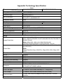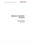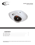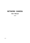
1
User Manual of Network Camera Version 1.0.0 Thank you for purchasing our product. If there is any question or request, please do not feel hesitated to contact us. This manual may contain several technical incorrect places or printing errors, and the content is subject to change without notice. The updates will be added to the new version of this manual. We will readily improve or update the products or procedures described in the manual. Safety Instruction These instructions are intended to ensure that user can use the product correctly to avoid danger or property loss. The precaution measure is divided into “Warnings” and “Cautions” Warnings: Serious injury or death may cause if any of the warnings is neglected. Cautions: Injury or equipment damage may cause if any of the cautions is neglected. Warnings Follow these safeguards to prevent serious injury or death. Cautions Follow these precautions to prevent potential injury or material damage. Warnings 1. In the use of the product, you must be strict compliance with the electrical safety regulations of the nation and region. 2. Input voltage should meet both the SELV(Safety Extra Low Voltage) and the Limited Power Source with AC 24V or DC 12V according to the IEC60950-1 standard. Please refer to technical specifications for more details. 3. Do not connect several devices to one power adapter as adapter overload may cause over-heat or fire hazard. 4. Please make sure that the plug is firmly inserted into the power socket. 5. When the product is installed on wall or ceiling, the device shall be firmly fixed. 6. If smoke, odor or noise rise from the device, turn off the power at once and unplug the power cable, and then please contact the service center. 7. If the product does not work properly, please contact your dealer or the nearest service center. Never attempt to disassemble the camera yourself. (We shall not assume any responsibility for problems caused by unauthorized repair or maintenance.) Notice: 1. Make sure the power supply voltage is correct before using the camera. 1 2. Do not drop the camera or subject it to physical shock. 3. Do not touch CCD (Charge Coupled Device) modules with fingers. If cleaning is necessary, use clean cloth with a bit of ethanol and wipe it gently. If the camera will not be used for an extended period, please turn on the lens cap to protect the CCD from dirt. 4. Do not aim the camera at the sun or extra bright places. A blooming or smear may occur otherwise (which is not a malfunction however), and affecting the endurance of CCD at the same time. 5. The CCD may be burned out by a laser beam, so when any laser equipment is on using, make sure that the surface of CCD will not be exposed to the laser beam. 6. Do not place the camera in extremely hot, cold(the operating temperature shall be-10℃~+ 60℃ ), dusty or damp locations, and do not expose it to high electromagnetism radiation. 7. To avoid heat accumulation, good ventilation is required for operating environment. 8. Keep the camera away from liquid while on using. 9. While on a delivery, the camera shall be packed in its original packing, or packing of the same texture. 10. Regular part replacement: a few parts (e.g. electrolytic capacitor) of the equipment shall be replaced regularly according to their average enduring time. The average time varies because of differences between operating environment and using history, so regular checking is recommended for all the users. Please contact with your dealer for more details. 2 INDEX CHAPTER 1 INTRODUCTION ............................................................................................................................................................. 4 1.1 NETWORK CAMERA FUNCTIONS AND FEATURES ............................................................................................................................... 4 CHAPTER2 INSTALLATION ................................................................................................................................................................ 5 2.1 PANELS DESCRIPTION ....................................................................................................................................................................... 5 2.1.1 Side Elevation of the Camera ............................................................................................................................................. 5 2.1.2 Rear Panel Description ........................................................................................................................................................ 7 2.2 PRODUCT INSTALLATION .................................................................................................................................................................. 9 2.2.1 Box camera Installation........................................................................................................................................................ 9 2.2.2 Dome camera Installation.................................................................................................................................................. 10 2.2.3 Topological graph of network camera...............................................................................................................................11 2.3 INSTALLATION OF CLIENT SOFTWARE 4000(V2.0) ...........................................................................................................................11 2.4 DS-2CD852, DS-2CD752 SERIES CAMERA MENU ILLUSTRATE AND E-PTZ OPERATION ......................................................... 13 2.4.1 752/852 series products e-ptz function....................................................................................................................... 13 2.4.2 752/852 series menu instruction................................................................................................................................... 13 2.4.3 762/862 series menu instruction................................................................................................................................... 21 CHAPTER3 PARAMETERS CONFIGURATION............................................................................................................................. 27 3.1 CONFIGURATION VIA WEB BROWSER .............................................................................................................................................. 27 3.2 CONFIGURATION VIA CLIENT SOFTWARE 4000(2.0) ................................................................................................................................. 30 CHAPTER 4 WAN ACCESS............................................................................................................................................................... 36 4.1 WAN ACCESS HAS A FIXED STATIC IP NETWORK CAMERA .............................................................................................................. 36 4.2 WAN ACCESS WITHOUT A FIXED STATIC IP NETWORK CAMERA ..................................................................................................... 37 CHAPTER 5 COMMON FAILURES AND MAINTAINANCE ......................................................................................................... 39 APPENDIX 1 SADP INTRODUCTION......................................................................................................................................................... 40 APPENDIX 2 PORT MAP .......................................................................................................................................................................... 42 APPENDIX TECHNOLOGY SPECIFICATION ................................................................................................................................ 44 3 Chapter 1 Introduction Network camera is a kind of embedded digital surveillance product that combines the features of both traditional analog camera and net DVS (Digital Video Server). Due to the embedded Linux operation system and the latest Davinci hardware platform of TI, the system operates with high scheduling efficiency. Furthermore, the firmware is burned in the flash, which makes the product small, reliable and highly stable. 1.1 Network camera Functions and Features DS-2CD852,DS-2CD862,DS-2CD752,DS-2CD762 series Network camera support standard MPEG-4 video Encoding and Oggvorbis,G.711 Voice Encoding techniques. DS-2CD852,DS-2CD752 series network camera support E-PTZ function. DS-2CD852,DS-2CD862,DS-2CD752,DS-2CD762 series network camera possess of OSD Menu, it can be display on screen by invoke 95th preview point on the client software or IE situation. Network Function :support the TCP/IP protocols(TCP/IP,HTTP,DHCP,DNS,RTSP RTCP,PPPoE,Furthermore,FTP,SMTP,NTP,SNMP addible),and IE browsing. Heartbeat Function: The server can acquire real time operating performance of the network camera through the heartbeat function. Alarm Function: The product includes 1 channel of alarm signal input and 1 channel of alarm on/off output, and supports motion detection, video missing, mask alarm and external alarm input.(Get details in Specification) Voice Talking:Support bidirectional voice talking and monomial voice broadcasting. User Management: Support multilevel right management. The administrator can create up to 15 separate users with different right levels, which highly improves the system security. DS-2CD852MF-E and DS-2CD752 series network camera support 12.5 frames per second (UXGA),12.5frames per second (HD900P), 25frames per second in PAL (4CIF,DCIF,2CIF,CIF,QCIF). And support 10frames per second (UXGA),15frames per second (HD900P), 30frames per second (HD720P),30 frames per second in NTSC(4CIF,DCIF,2CIF,CIF,QCIF). Note: UXGA(1600*1200),HD900(1600*912). DS-2CD862MF-E and DS-2CD762 series support 25 frames per second(HD720P and VGA) and 12.5 frames per second(XVGA).Note:XVGA(1280*960),HD720(1280*720), VGA(640*480). The product offers a 10M/100M self-adaptive Ethernet interface. Support set the parameters, browse real time videos or check the camera performance through software or IE, and get external alarming and store the compressed bit rate through network. Support remote upgrades and maintenance. RS-485 supports monomial transparent channel function so that clients on remote PC can control the serial devices. 4 Chapter2 Installation [NOTICE] 1. 2. 3. 4. 5. Please check if all the items on the package list have been included with your camera. Read the following contents carefully before the installation. Make sure that all the related equipment is power-off during the installation. Check the power supply to prevent any damage caused by mismatching problems. This product is not for any environment of high humidity or high temperature. Conditions of rain, airlessness or frequent shaking are also prohibited. 6. If the product does not operate properly, please contact your dealer or the nearest service center. Never attempt to disassemble the camera yourself. Users are responsible for any problem caused by modification or repairing without authorization. 7. Power Supply, Lens and SD card are Optional. 2.1 Panels Description 2.1.1 Side Elevation of the Camera Fig 2.1.1 Side Elevation of DS-2CD852 series camera Fig 2.1.2 Side Elevation of DS-2CD862 series camera 5 Fig 2.1.3 Side Elevation of DS-2CD752、DS-2CD762 series camera Fig 2.1.4 Side Elevation of DS-2CD752MF-FB(H)、DS-2CD762MF-FB(H) series camera 6 2.1.2 Rear Panel Description Fig. 2.1.5 Rear Panel of DS-2CD852, DS-2CD862 series camera 1、Standard Ethernet (UTP) RJ45 (10M/100M self-adaptive). 2、1 channel voice talk input,3.5mm audio interface, 2.0~2.4Vp-p, 1kΩ. 3、1 channel voice talk output, 3.5mm audio interface, electric line level, 600Ω. 4、ANT, connect to Antenna. Open this port as necessary. 5、1 channel alarm output (1A 1B). 6、1 channel alarm input signal (IN,G). 7、RS-485 bus interface(T+ T-) 8、Video Output port. 9、SD card slot. 10、PWR power supply indicate LED. 11、AC24V and DC12V power supply port. 7 Fig. 2.1.6 Rear Panel of DS-2CD752 、DS-2CD762 series Address& protocols dial switch, define for dial switch: , from 1 to 5 dial switch function as follows: Switch 1 2 3 4 5 Function ON OFF SHARP AES BLC FL NAGC SOFT AI OFF ON SAGC Notices: There are invalid dial switches for DS-2CD752、DS-2CD762 series from 6 to 10; 8 2.2 Product Installation 2.2.1 Box camera Installation Box camera can be fixed in both metope and ceiling. Customers can choose whichever way according to their specific needs. Please follow the steps below:(Take fixing in ceiling as an example, fixing in metope follows the same rule).Choose the fixing method and fix the camera bracket accordingly. If it is metope, then you need to fix the expand bolt (note: the mounting hole of the expand bolt should align with the bracket) before fixing the bracket. If the wall surface is wooden, the first step can be ignored and you can use the self-tapping screw to directly fix the bracket. Please note that the metope on which the camera is fixed should be able to bear at least three times the weight of the bracket and the camera. Fig 2.2.1 Fix Ceiling Bracket Fig 2.2.2 Fix Camera Fig 2.2.3 Fix Lens 9 2.2.2 Dome camera Installation Dome camera can be installed include hold equipment,ceiling mounted,cylinders and other styles. Client can be installed in accordance with their own ways to achieve the installation.Please according the following specific steps to install (take ceiling mounted as example), when the wall is wood, use the self-tapping screws to fix the ceiling plate to the wall surface. Fig 2.2.4 Fix card Fig 2.2.5 Fix in Ceiling Take the three columns of Dome camera insert in the three fix slot of the ceiling plate. Pay attention to the direction of insertion. Let the ceiling plate “I” logo and the Dome camera “I” logo in the same direction. Meanwhile, make the Dome camera along the counterclockwise Rotate 15 degrees until the switch to the fixed date. At the same time, the Dome camera on the “I” signs and ceiling plate on the locking screw plate alignment. Ceiling locking plate on the locking screw. Fig 2.2.6 Dome camera fixing Fig 2.2.7 Dome camera fixed 10 2.2.3 Topological graph of network camera Fig 2.2.8 Topological Graph of DS-2CD852、DS-2CD862 series Physical Interface UTP Network Interface Audio Input(AIN) Audio Output(AOUT) Power Supply(DC12V) Connection Connect to network devices, such as switch , HUB, etc. Please refer to Appendix B for pin Definition. Connect to audio input devices such as active tone (2.0~ 2.4Vp-p, 1kΩ) Connect to sounders like loudhailer 600Ω. Please refer to the appendix for specified types. Please use a matched regulator. Alarm Output(1A 1B) 1 channel alarm out. Please refer to Section 2.3.2 for connecting instructions. (external series-wound power shall be under 12V DC / 30mA) Alarm Input(IN G) RS-485 Interface(T+ T-) SD card slot Video Output(VOUT) 1 channel alarm in. Connect to RS-485 devices like PTZ. Insert an SD card for local storage, support SDHC Standard BNC, connect to monitor. 2.3 Installation of Client software 4000(V2.0) Note: It is recommended that users computer adopted INTEL P3,P4,C4,Core4 CPU, and well-known brands (Asus, Gigabyte, MSI,ECS,INTEL etc.)Intel chipset motherboard, to ensure the stability of the 11 system. Tested the following models of the current graphics cards support the softwareinstalled,ATIRadeonX1650,X1600,X1550,X1300,X800,X600,X550,HD2400,HD2600,NVIDIA GeForce 8600GT,8500GT,8400GS,7600,7300LE,6600LE,6200LE,INTEL915/945G,pay attention to graphics driver must support hardware scaling function. Double click the software and you will see the wizard shown as below: Click “Next” to continue, and input the user information, software installed location according to the hints. After that, a SADP installation wizard will pop up; click “Next” to start to install WinPcap, shown as below. If it is already installed, the installation can be canceled. Note: SADP is used as the on-line device finder; this function is unavailable if the WinPcap is not installed. 12 Click the “Finish” button to close the dialog box. After the client software being installed, you can find the remote client software through “Start” -> “Program” on your PC 2.4 DS-2CD852, DS-2CD752 series camera Menu illustrate and e-PTZ operation 2.4.1 752/852 series products e-ptz function Under the resolution of QCIF/CIF/DCIF/2CIF/VGA/D1/SVGA, support pan\tilt\zoom operation, pan and tilt operation can be carried out only after zooming in,Support 127 preset positions(95 excluded,used to call menu)。Cruise path supports the preset of movement from Top left-hand corner of the screen to the bottom right-hand, support manual disposition too.HD720p resolution only supports pan and tilt operation,does not support zoom operation。UXGA resolution does not support e-ptz function。 Max support frame rate: DS-2CD852MF-E/DS-2CD752MF-E: 50Hz QCIF/CIF/2CIF/DCIF/VGA/D1/SVGA/HD720p 25fps /UXGA 12.5fps /HD900 12.5fps 60Hz QCIF/CIF/2CIF/DCIF/VGA/D1/SVGA 30fps /HD720p 15fps/ UXGA 10fps/HD900 15fps Support vlc standard media player, connected as below(default): Main code rate:rtsp://admin:[email protected] Sub code rate:rtsp://admin:[email protected]/mpeg-4/ch1/sub/av_stream Attention: 852F/752F will force to reboot when change the resolution to UXGA or HD720p. 2.4.2 752/852 series menu instruction 1、Display menu Invoke Pre-set position95;Double click presetting points of “95th ”,main menu display on screen . <MAIN MENU > LANGUAGE CHINESE/ENGLISH FLICKER CONTROL 50Hz RESOLUTION CIF FRAME 25fps SHUTTER OFF AUTO GAIN LOW DAY/NIGHT Auto WHITE BALANCE Auto EFFECTS MODE OFF MIRROR OFF EPTZ OFF <EXIT> <SAVE> Select OSD menu by PTZ control key, as follows: 13 ※ U P ↑: ※ DOWN↓: ※ LEFT ← : ※ RIGHT→: Attention: Means select OSD menu item Means select OSD menu item Means select parameter on OSD Means select parameter on OSD Parameter on OSD exception “FLICKER CONTROL”, others become effective in time Parameter on OSD of “RESOLUTION” and “FRAME” are only for usage of display, and can not be selected by left and right key. 2、Exit menu “Iris+”means『enter』,you can select “save”、“cancel” or “preset” according to the exit options. 3、Menu detailed operations The menu selection is implemented through “up” “down” “left” “right” buttons, you can select the menu function by “up” “down” buttons, and the subentry of the specified function by left” “right” buttons. ◆Language CHINESE ENGLISH Switch CHINESE/ENGLISH by left” “right” buttons ◆Flicker control 50Hz 60Hz The switch between 50Hz and 60Hz will take effect after clicking “Iris+”. ◆Resolution This option is used for displaying the current resolution, can’t be controlled by “left” “right” buttons. ◆Frame This option is used for displaying the output frame rate, can’t be controlled by “left” “right” buttons. 14 OFF ◆Shutter AUTO×2 AUTO×5 “OFF” The regulation of shutter exposure time is default. “AUTO×2” The regulation of shutter exposure time is considerably wider. “AUTO×5” The regulation of shutter exposure time at its maximum. DS-2CD852MF-E Resolution DCIF CIF QCIF 4CIF 2CIF VGA SVGA UXGA HD720p HD900 50Hz Auto×2 Auto×5 25fps 12.5fps 5fps 12.5fps 25fps 12.5 12.5fps 12.5fps 12.5fps 5fps 5fps 5fps OFF 60Hz Auto×2 Auto×5 30fps 15fps 5fps 10fps 15fps 15fps 10fps 15fps 15fps 5fps 5fps 5fps 60Hz Auto×2 Auto×5 15fps 5fps OFF DS-2CD752MF-E Resolution OFF DCIF CIF QCIF 4CIF 25fps 2CIF 50Hz Auto×2 Auto×5 12.5fps 5fps OFF 30fps 15 VGA SVGA UXGA HD720p 12.5fps 25fps ◆AUTO GAIN 12.5fps 12.5fps 5fps 5fps 10fps 15fps 10fps 15fps 5fps 5fps OFF LOW MEDIUM HIGH You can set up different auto gain values separately in the condition of low illumination, and increase the picture brightness. This function may not only be independent employment, but also coordinate with option selections in shutter establishment, in order to achieve better low light illumination mode effect. ◆DAY/NIGHT Auto Color B&W 16 In the condition of low illumination, the auto mode has a better noise cut-down effect compared with color mode. ◆WHITE BALANCE Auto OFF “Auto” “OFF” Enable the auto W&B of the current screen Based on the current W&B state,no more auto adjustment. ◆EFFECTS MODE OFF SEPIA NEGATIVE SOLARIZE1 SOLARIZE2 17 If B&W is switched to color mode,this function is compelled to be “OFF”。 ◆MIRROR OFF LEFT RIGHT UP BOTTOM CENTER 18 ◆e-PTZ OFF ON “OFF” Means support mechanical PTZ only “ON” Means support e-PTZ function only ◆EXIT SAVE CANCEL DEFAULT This mode is employed after clicking “enter” buttons. 19 “SAVE” Save the current configuration “CANCEL” Cancel with the current operations,restore to the configuration before carrying out the operations. “DEFAULT” Restore to the default configuration 20 2.4.3 762/862 series menu instruction 1、Display menu Invoke Pre-set position95;Double click presetting points of “95th ”,main menu display on screen . <MAIN MENU> LANGUAGE ENGLISH RESOLUTION HD(1280*720) FRAME 25fps LENS AI SHUTTER 1/25s AUTO GAIN OFF DAY/NIGHT DAY WHITE BALANCE ATC BACKLIGHT COMP. MANUAL … MIRROR OFF <EXIT> <SAVE> Select OSD menu by PTZ control key, as follows: ※ U P ↑: ※ DOWN↓: ※ LEFT ← : ※ RIGHT→: Means select OSD menu item Means select OSD menu item Means select parameter on OSD Means select parameter on OSD 2、Exit menu “Iris+”means『enter』,you can select “save”、“cancel” or “preset” according to the exit options. 3、Menu details operations The menu selection is implemented through “up” “down” “left” “right” buttons, you can select the menu function by “up” “down” buttons, and the subentry of the specified function by “left” “right” buttons. ◆Language CHINESE ENGLISH Switch CHINESE/ENGLISH by ” left” and “right” buttons. 21 ◆Resolution This option is used for displaying the current resolution, can’t be controlled by “left” “right” buttons. But it can be controlled by remote setting option. Notice: as for DS-2CD862、DS-2CD762 series camera , they are support XVGA(1280*960) per second 12.5 frames and HD720P(1280*720) ,VGA(640*480) per second 25frames ◆Frame This option is used for displaying the output frame rate, can’t be controlled by “left” “right” buttons. Under the resolution of HD720P (1280*720) and VGA (640*480), it is real time 25fps/s Under the resolution of 1280*960 per second 12.5 frames. ◆Lens AI AES Support “Auto Iris” and “Auto electron shutter” two mode. ◆Shutter Auto --- Support “auto” and “---” two mode.When select “ Auto Iris”(AI) , Shutter can be selected by as list: 1/25s,1/50s,1/100s,1/250s,1/500s,1/1ks,1/2ks,1/4ks,1/10ks,1/100ks. When select “AES”, and it support “Auto ” electron shutter. ◆Auto gain High Middle Low 22 Off When select “ Day” or “Night” mode at “DAY/NIGHT” option, Auto Gain support High、Middle、 Low、Off option. When select “Auto ” mode , Auto Gain will display “---” option. You can set up different auto gain values separately in the condition of low illumination, and increase the picture brightness. This function may not only be independent employment, but also coordinate with option selections in shutter establishment, in order to achieve better low light illumination mode effect. ◆Day/Night Auto… Day Night Support “Auto…”、”Day”、”Night” three mode optional setting; Select “Auto…” mode, and click Iris[+], entry in Auto IR-CUT Setting. AUTO IR-CUT SETTING VALUE HIGH、MIDDLE、LOW(menu selection is implemented through “up” “down” “left” “right” buttons) TIME 5s、10s、15s、20s、25s(menu selection is implemented through “right” buttons) 23 “up” “down” “left” ◆White balance ATW1 ATW2 ATC MWB… When select “Night” mode , white balance option will display “---”, means not support setting by manual. When select “Auto” or “Day” mode ,white balance support setting by manual; ATW 1 ATW 2 ATC MWB SETTING Auto or Day TEMP. MWB…(click Iris[+],entry OSD) ADD/SUB BACK 24 ◆Backlight Comp. Off Manual… Support “Off” and “Manual…” two mode; When select “Manual…” at Backlight Comp. option, the position and size of Backlight Comp. can be setting by manual. BACKLIGHT COMP. BLA MANUAL… POSITION… UP SIZE… Manual…(click DOWN BACK Iris[+],entry OSD) LEFT RIGHT Notice : The parameter of CENTER position and size can be set BACK by click Iris[+] “Right”, ”Left” buttons. Notice:Up、DOWN、LEFT、RIGHT、 CENTER、MANUAL… option can be set by click “Right”, ”Left” buttons. 25 and ◆Mirror Off Left Right Up Bottom Center Support “Off”、”Left Right”、”Up Bottom”、”Center” mode, and set by “left” “right” buttons ◆Exit Save Cancel Default This mode is employed after clicking “enter” buttons. “SAVE” Save the current configuration “CANCEL” Cancel with the current operations,restore to the configuration before carrying out the operations. “DEFAULT” Restore to the default configuration 26 Chapter3 Parameters Configuration There are several network parameters of the camera those need to be set after the hardware installation. Those parameters including IP address, subnet mask and port number, etc. which can be set through various kinds of methods, 2 of them are introduced as below. 1. Set the camera parameters such as IP address and PPPOE through IE. 2. Set the camera parameters through the client software. Please make sure that the PC and network camera are connected and can ping successfully before the parameter setting. 2 different ways of connections are showed as Fig. 3.1 & Fig. 3.2. Fig.3.1 Direct Line Connection Fig.3.2 Cross Line Connection 3.1 Configuration via Web browser Before visit the camera via web browser, user should adjust security level. Open the web browser, and enter the menu “Tool/ internet option/Security/Custom level”, then set the security level to Security Level –Low, or enable ActiveX Control and the Plug-in directly. Figure 3.3 gives you a visual illustration. After you can see the camera video, recover the security level for security. 27 Fig. 3.3 Set the Security Level The default IP of the camera is 192.0.0.64 with 8000 as the default port, admin as the administrator, and 12345 as the password. The administrator can create up to 15 separate operators with different right levels. 28 To login the camera through IE, input the IP address in the address column, and the “Login” dialog box will pop-up as Fig. 3.4. Input your user name and password, and then click “Login” to enter the “preview” page. Double click the “Camera 01” channel or “Preview” button to preview the video as Figure 3.5. Right click the “Camera 01” channel, and the “Main Stream”, “Sub Stream” and “Open sound” options will popup. Select the Open sound option if you connect a pickup to the camera. Fig. 3.4 Login Interface Fig 3.5 Preview Interface The “Playback” and “Log” functions can be used only in the condition of existing SD card. To set the camera parameters through IE browser, click “Config” and wait for the “Remote Parameters Config” dialog box to pop up, and then set the parameters like IP address, etc. for your demand as Fig. 3.6. Enter the menu by invoking the 95th preset. Select the function you want by clicking the direction key. Click the IRIS+ button you can enter the submenu. The menu operation is like the remote control. 29 Note: If plug the SD card into the camera, user should enter the “config” and select “other function” to format the SD card. For more specific information of “Remote Parameters Config”, please refer to “Instructions of Client Software (version 4.01)” from Section 2.5.3 of remote-distance parameter settings. Instructions can be found in the client software4.01 in the path of “Start” → “Program”→ “client software 4.01” after installation. Fig. 3.6 Remote Parameters Configuration 3.2 Configuration via Client Software 4000(2.0) After the installation of client software 4000, click the “client software 4000” in “Start”→ “Program”→ “client software 4.01”, a message box of “Register Administrator” as Fig. 3-2-1 will appear by then for the first time running. Password should be no less than 6 digits for registration. Note: Please keep the user name and password in mind .You may not be able to get access to the software if any of them is missing. 30 Fig.3.2.1 Register Administrator Enter the registered user name and password as Fig. 3.3.2. Click “Login” to enter the “Preview” menu as Fig. 3.2.3. Fig. 3.2.2 User Login Fig. 3.2.3 Preview Menu Click the “Configure” button in Fig. 3.2.4, and then right click the blank spaces in the middle. Click the “Create Root Node” button, and the “Area Properties” message will pop up as fig 3.2.5. 31 Fig. 3.2.4 Create Root Node Fig. 3.2.5 Area Properties Input the area name (you can create whatever name you like) and click “OK” as Fig. 3.2.6. Then right click the area name you have just created as Fig. 3.2.7. 32 Fig. 3.2.6 Area Name Adding Completed Fig. 3.2.7 Right Click the Area Name Click “Add Device”, and the “Server Properties” dialog box will pop up as Fig. 3.2.8. Input your “Server Name” and select “HC” from the “Server Type” option. Select “Normal” from “Register” option. Input your camera IP in “Server IP”, e.g. 192.0.0.64; “User Name”: admin, “Password”: 12345, and 8000 for the default “Port”, and then modify “Channel” to 1. Click the “OK” button as Fig. 3.2.8. 33 Fig. 3.2.8 Add Device Fig.3.2.9 Camera Adding Completed Click the “Preview” button to enter the “Preview” menu as Fig. 3-2-10. Double click the channel name in the left tree to preview the pictures. 34 Double click the channel Fig.3.2.10 Preview Menu Please refer to “Network Video Surveillance Software Operation Instruction (4000)” for more detailed parameters configuration. You can find the document in PC Operating System after the installation of client software 4000 by selecting “Start”-> “Program”-> “client software 4000”. Fig.3.2.11 Remote Configuration 35 Chapter 4 WAN Access The IP protocol supports WAN access based on PPPoE dial up function. Make sure that the software you are using supports the function before using these network functions. 4.1 WAN access has a fixed static IP Network Camera 1、If the network camera adopt static IP address directly access the public network. And access to network camera through IE only required to fill in the IE address bar to set static IP; If adopt client software to access camera, in the adding equipment column, select the general IP model, and fill IP. At last, user should through client software or IE to enter an IP for the implementation of remote access equipment. Fig.4.1 Static IP Configuration dialog box 2、If the network camera has a static IP through the router access to the public Network. Should set the network camera equipment port(default 8000), HTTP port (default 80) ,RTSP port 554 and data preview port 8200 on the router and make a port mapping, then adopt the client software or IE to access the network camera. Fig.4.2 Port mapping 36 4.2 WAN Access without a fixed static IP Network Camera 1、If the network camera through PeanutHull domain name or other means of public Network access. Please connect the camera to router, set the camera IP address, netmask, gateway and routers in the same network segment. Router through the peanut shells and other DNS domain name to get a public network IP address, then make a port mapping, if the router has a dynamic IP, may as well through router DDNS feature to bind the domain name. Port mapping and bind the domain name see Fig as follows. Fig.4.3 Port mapping Through input domain names in client software or IE to access the network cameras, take access the Client software configuration as an example. Fig.4.4 Configuration of domain name in Client software 37 2、If the network camera through IPSERVER access the public network. The camera support PPPoE auto dial-up function, connect camera to Modem for dial-up access the ADSL network and get an public IP address; First, through local network access network camera, select[Configure]----[Network Configuration] dialog box, enable PPPoE, fill PPPoE user name and password and confirm the password, Please restart the network after the completion of the camera. After the success of equipment that will be resumption of ISP operators to provide a dynamic IP address. For the obtain IP address is dynamically assigned by the means of PPPoE, and the IP address always change, however, it can be used at a public network with a static IP address on the PC machine running the IPSERVER software (DNS software), Take run the software PC’ IP address as the DNS address of the network address, in the same time, IP address, product serial number and other information will be found at this IPSERVER software. At the “Add Device” dialog box of the Client software, Selected the “Registration Mode” as the “Private domain name” , then click Preview means enter preview interface, at last can see the display of video. Attention:DS-2CD852、DS-2CD862 and DS-2CD762、DS-2CD752 series network camera need to open RTSP port 554, other than open 80 & 8000 & 8200 ports. Fig.4.5 PPPoE configuration dialog box Fig.4.6 Private Domain and DNS IP setting dialog box 38 Chapter 5 Common failures and maintainance 1、Power on failure Check if the power plug is fixed into the socket or if the power supply is working correctly. 2、Image blurry Check if the lens connector is correct. There are two types of bayonets—the C and CS which are different; Adjust lens focus and back focal. 3、SD card not working properly Check if the SD card is well fit into the IP camera and if the SD card slot is intact. If the system does not recognize the SD card, check if the SD card is intact. 4、What’s the relationship between the image quality, resolution and browsing speed under certain bandwidth? Under certain bandwidth, the image quality, resolution and browsing speed have a relationship of mutual restriction. The better the image quality, the higher the resolution, which will inevitably consume more bandwidth, thus browsing will become more retarded. In practical application, we can set the image quality (best image quality, standard, highest browsing speed ) according to the bandwidth 5、Unable to connect Check if the reticle works correctly and if the Link led is on. 6、Can network camera be used in glaring environment? Glare like direct sunshine or halogen lamp will cause the CMOS, CCD sensor overload, because long-time exposure to strong light may burn the image sensor. 7、How long can the reticle of IP camera extend? Generally, the LAN Cable and UTP Cable can extend to 100m. If any of the above information cannot meet your demands, please contact your dealer. 39 Appendix 1 SADP Introduction 1. Brief introduction SADP (Search Active Devices Protocol), can automatically search IP cameras in LAN. User can modify the IP address, subnet mask and port of the device without visiting IP address of the device. Additionally, password of the super user in this device can be recovered as default. SADP software needs to support sadp, so we should install WinPcap at first, which is placed at the directory of SADP software. 2. Searching active devices online After installing WinPcap, double click sadpdlg.exe. The software will start to search active devices in LAN, and device type, IP address, Port number, Device Serial No., subnet mask, MAC address, the number of channels, main control and encoding version and device initiating time are showed in the list, as following: 3. Modifying the information of active devices Select the device that needs modification in the device list, then basic information of the device will be demonstrated in the information column on the right. Click ‘modify’ button to activate IP address, subnet mask, device port editing and password validating box, as following: 40 Input new IP address, subnet mask, and port number, and click ‘save’ button. If a dialog pops up, showing ‘saved successfully’, that means you have modified the configuration information; if ‘saving failed’ turns up, click the ‘cancel’ button to quit it. 4. Recovering default password You can reset the password of the super user as ‘12345’ in case of can not remembering administrator’s password. Input certain validate code into ‘recover device default password’ column, and click ‘OK’ to finish the administrator’s password initiating. Note: validate code is sent by the technicians after you provide the device Serial NO. 41 Appendix 2 Port Map Note: The following setting is about TP-LINK router (TL-R410), which is maybe distinct from other router’s setting. 1. Firstly, select the router’s WAN connection Type. As the following Fig. shows: 2. Set the “network parameter” of the router as the below figure. The setting includes subnet mask and gateway. 3. Set the port map in the virtual severs of Forwarding. The following figure gives the illustration. One camera’s ports are 80, 8000 and its IP address is 192.168.1.23. The other camera’s ports are 81, 8001 and IP is 192.168.1.24. Afterwards, enable all or TCP protocols. Enable the port map after pressing the ‘Save’. 42 As the above mentioned setting, we map the router’s port 80, 8000 to the network camera 192.168.1.23; and port 81, 8001 to the network camera 192.168.1.24. In this way, user can visit the 192.168.1.23 through visiting the router’s port 80, 8000. Note: The port of the network camera cannot conflict with other ports. For example, some router’s web management port is 80. User can amend the router’s or the camera’s port to solve this problem. 43 Appendix Technology Specification Table 1 Parameter Model Camera Image Sensor Effective Pixels Min. Illumination Electronic Shutter Auto Iris Lens Day&Night Lens Lens Mount Video Output Compression Standard Video Compression Video Output Audio Compression Image Image Resolution Frame Rate Functions e-PTZ Motion Detect Dual Stream SD Card Local Recording Heartbeat Password Protect Protocols DS-2CD852MF-E DS-2CD852MF-E(CUT) 1/3 inch CMOS 1600(H)×1200(V) 0.5Lux/F1.2 0.1Lux/F1.2, sensitization X5 Auto -----Electronic ICR Option C/CS mount 1Vp-p Composite Output(75Ω/BNC) MPEG-4 32 K~2M, adjustable( 8Mbps maximum) OggVorbis 50Hz:1600x1200, 1600 x912,1280x720,800x600,704x576,640x480,528x384,704x288,35 2x288,176x144 60Hz:1600x1200, 1600 x912,1280x720,800x600, 704x480,640x480,528x320,704x240,352x240,176x120 50Hz:25fps(704x576),25fps(1280x720),12.5fps(1600x1200),12.5f ps(1600 x912) 60Hz: 30fps(704x480),15fps(1280x720),10fps(1600x1200),15fps(1600 x912) Support Support Support Support Support Support TCP/IP,HTTP,DHCP,DNS,RTCP,RTSP,PPPoE (FTP,SMTP,NTP,SNMP addible) Interface Voice Talk Input 1 channel 3.5mm audio interface(2.0~2.4Vp-p,1kΩ) Voice Output 1 channel 3.5mm audio interface(Line level, 600Ω) Communication Alarm Input 1 RJ45 10M/100M self-adaptive Ethernet port and 1 RS-485 interface 1 channel relay input 44 Alarm Output 1 channel relay output Others Working Temperature -10℃~60℃ Power Supply AC24V±10%/DC12V±10%, PoE (Power over Ethernet). Power Consumption 4W MAX Dimensions (mm) 64.8x63x157.5 Weight 600g Notice: (-E) illustration of support PoE (power over ethernet) (-F) illustration of support local SD card storage (-W) illustration of support IEEE802.11g wireless Ethernet criterion Table 2 Parameter Camera Image Sensor Effective Pixels Min. Illumination Electronic Shutter Auto Iris Lens Day&Night S/N Ratio Lens Lens Mount Video Output Compression Standard Video Compression Video Output Audio Compression Image Image Resolution Frame Rate Functions e-PTZ Motion Detect Dual Stream SD Card Local Recording Heartbeat Password Protect Protocols Interface Voice Talk Input Voice Output Model DS-2CD862MF-E 1/3 inch SONY progressive scan CCD 1280(H) ×720(V), 1.3M CCD 0.1Lux @ F1.2 1/4s-1/100,000 s DC/Video ICR Cut More than 50dB Option C/CS mount 1Vp-p Composite Output(75Ω/BNC) MPEG-4 32 K~2M, adjustable( 8Mbps maximum) OggVorbis 1280×960,1280×720, 640×480 25fps(1280×720, 640×480),12.5fps(1280×960) Support Support Support Support Support Support TCP/IP,HTTP,DHCP,DNS,RTCP,RTSP,PPPoE (FTP,SMTP,NTP,SNMP addible) 1 channel 3.5mm audio interface(2.0~2.4Vp-p,1kΩ) 1 channel 3.5mm audio interface(Line level, 600Ω) 45 1 RJ45 10M/100M self-adaptive Ethernet port and 1 RS-485 interface 1 channel relay input 1 channel relay output Communication Alarm Input Alarm Output Others Working Temperature -10℃~60℃ AC24V±10%/DC12V±10%, PoE Power Supply Ethernet). Power Consumption 4W MAX Dimensions (mm) 68.5x63x157.5 Weight 600g Notice: (-E) illustration of support PoE (power over ethernet) (-F) illustration of support local SD card storage (-W) illustration of support IEEE802.11g wireless Ethernet criterion (Power over Table 3 Parameter Camera Image Sensor Effective Pixels Lens Min. Illumination Video Output Day&Night Compression Standard Video Compression Video Output Audio Compression Image Image Resolution Frame Rate Functions Motion Detect Dual Stream Model DS-2CD752MF-E 1/3 inch CMOS 1600(H)×1200(V) 2.8-11mm,F1.4 manual Iris lens 0.5Lux/F1.2 0.1Lux/F1.2, sensitization X5 1.0Vp-p Composite Output(75Ω/BNC) Electronic MPEG-4 32 K~2M, adjustable(8Mbps maximum) OggVorbis 50Hz: 1600x1200,1600x912,1280x720,800x600,704x576,640x480,52 8x384,704x288,352x288,176x144 60Hz: 1600x1200,1600x912,1280x720,800x600,704x480,640x480,52 8x320,704x240,352x240,176x120 50Hz: 25fps(704x576),25fps(1280x720),12.5fps(1600x1200),12.5fps( 1600 x912) 60Hz: 30fps(704x480),15fps(1280x720),10fps(1600x1200),15fps(160 0 x912) Support Support 46 SD Card Local Recording Heartbeat Password Protect Protocols Interface Voice Talk Input Voice Output Support Support Support TCP/IP,HTTP,DHCP,DNS,RTCP,RTSP,PPPoE (FTP,SMTP,NTP,SNMP addible). 1 channel (2.0~2.4Vp-p,1kΩ) 1 channel (Line level, 600Ω) 1 RJ45 10M/100M self-adaptive Ethernet port and 1 RS-485 interface 1 channel relay input 1 channel relay output Communication Alarm Input Alarm Output Others Working Temperature -10℃~60℃ Power Supply 12VDC, ±10%, (-E) series support PoE (Power over Ethernet) Power Consumption 4W MAX Dimensions (mm) φ145x132.8 Weight 900g Notice: (-E) illustration of support PoE (power over ethernet) (-F) illustration of support local SD card storage (-W) illustration of support IEEE802.11g wireless Ethernet criterion Table 4 Model Parameter DS-2CD752MF-FB(H) DS-2CD762MF-FB(H) Camera Image Sensor 1/3 inch CMOS 1/3 inch SONY progressive scan CCD 1280(H)X 720(V), 1.3M CCD 0.1Lux @ F1.2 Effective Pixels Min. Illumination Lens Day&Night Compression standard Video Compression Video Output Voice Compression Image Image Resolution 1600(H)×1200(V) 0.5Lux/F1.2 0.1Lux/F1.2, sensitization X5 3.3-12mm/F1.4/ manual Iris lens Electronic 3.3-12mm/F1.4 /Auto Iris lens MPEG-4 32 K~2M, adjustable(8Mbps maximum) OggVorbis 50Hz:1600x1200,1280x720,800x60 0,1600×912 704x576,640x480,528x384,704x28 8,352x288,176x144 1280×960,1280×720, 640×480 60Hz:1600x1200,1280x720,800x60 0, 1600×912,704x480,640x480,528x3 20,704x240,352x240,176x120 47 Frame Rate 50Hz:25fps(704x576),25fps(1280x 720) 12.5fps(1600x1200),12.5fps(1600× 912) 60Hz: 30fps(704x480),15fps(1280x720) 10fps(1600x1200),12.5fps(1600×9 12) 25fps(1280×720, 640×480) 12.5fps(1280×960) Function e-PTZ Support NO Motion Detect Support Dual Stream Support SD Card Local Support Recording Heartbeat Support Password Protect Support Protocols TCP/IP,HTTP,DHCP,DNS,RTCP,RTSP,PPPoE(FTP,SMTP,NTP,SNMP addible) Interface Voice Talk Input 1 channel(2.0~2.4Vp-p,1kΩ) Voice Output 1channel (Line level, 600Ω) Communication 1 RJ45 10M/100M self-adapted Ethernet port and, 1 RS-485 interface Alarm Input 1 channel relay input Alarm Output 1 channel Relay output Others Working Temperature -10℃~60℃ (“-H” series support-40℃~60℃) Power Supply AC24V±10%/DC12V±10% ,or PoE (Power over Ethernet) Power Consumption 4W MAX(14W MAX heat) 5W(15W MAX heat) Heat / Scatter Heat “-H” series support Impact Protection IEC60068-275Eh,50J;EN50102, exceeding IK10 Water and Dust IP66 Resistance Dimension(mm) φ156x134.5 Weight 1400g Notice: (-E) illustration of support PoE (power over ethernet) (-F) illustration of support local SD card storage (-W) illustration of support IEEE802.11g wireless Ethernet criterion 48