1
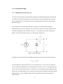
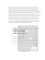
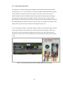
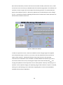
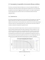
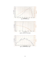
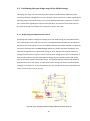
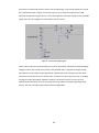
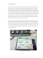
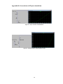
Once this has been done, the user sets the correct number of CSBs, selects the curve, as well
as the short circuit current (Isc) in DEFINE mode of the Labview programme. The Labview user
interface is shown in Figure 18. As the output from the DC generator
equal to the simulator input
/
would initially be
without any adjustments, the desired open circuit voltage
must be fine-tuned by adjusting the Rvoc while in TUNE mode. These operations are
documented in detail in Section 3.1.
Figure 18 - Labview user interface
In order to capture the curves, a DUT was needed to set the voltage ranges to be applied
across the diode strings. In this test, an IV curve tracer was utilised and connected at the
output of the simulator. A dedicated software comes with the tracer and operating
instructions were obtained from the DS-100C I-V CURVE TRACER User Manual (17). The IV
curve tracer obtains the curve by receiving the output from the PV simulator
and
varying the impedance of the output from zero to infinity which is done by connecting it to a
capacitor. As the capacitor charges, the operating range of the simulator’s output is recorded,
starting at Isc and finishing at Voc. Information regarding the IV curve tracer (DS-100C) is
available electronically in Appendix E.
36