1
Chapter Two - Familiarisation with PV array Simulator
Familiarization of the PV array Simulator was prepared with the available documentation,
manuals, as well as a visit from Andrew Ruscoe, who was involved in the development of the
RESLab PV array simulator. Prior to his visit, the PV Simulator Software Specification &
Description (1) was utilised to understand the controls that were needed to operate the
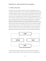
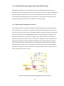
simulator. It is understood that the System Control acts as a control platform for the simulator.
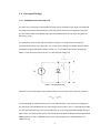
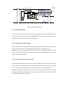
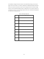
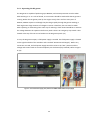
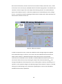
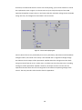
Within the System Control are three different controls. They are respectively the Current
Control, Main Control, and Supervisory & Operational Control. Their positions within the
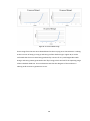
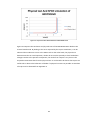
System Control are displayed in Figure 2 below. (1)
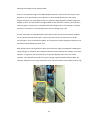
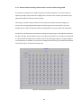
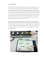
The Labview programme PVSimulator v7, which is the user interface, was located on the RISE
network drive and was uploaded to a computer nearest to the simulator for ease of use. A
configuration was also done to adjust for the correct settings so that the Field Point Units
would be able to communicate with the computer. (1)
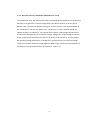
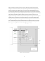
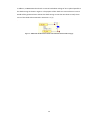
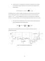
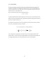
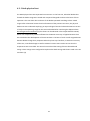
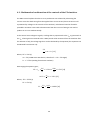
The overall operation of the simulator involves the initial application of
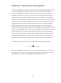
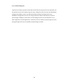
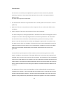
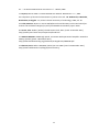
(DC input voltage
to the PV array Simulator) through the CSBs. A 50V voltage drop occurs across the CSBs, and
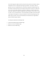
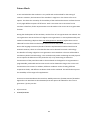
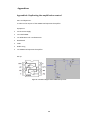
the resultant voltage
(DC output voltage of the PV array Simulator) is fed into the DUT.
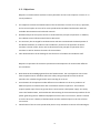
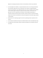
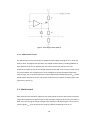
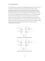
The DUT determines the PV array Simulator voltage that is adjusted before being fed back to a
selected diode string in Main Control. In addition, the Main Control generates a user defined
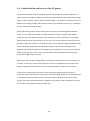
short circuit current and subtracts the diode current from it. A current source control signal,
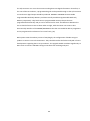
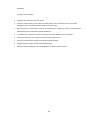
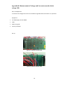
, is then generated (also from Main Control) and passed through to the current source
blocks which is ensured by Current Control. The Supervisory & Operational Control controls and
monitors the operation of the simulator. The details of each control are documented in the
following sections. (1)
8