1
4.1.2 - Measurement of Voltage and Current across the diode strings PCB
The previous test (Section 4.1.1) did not present an output. However, it was learnt that the
operating voltage range would not be higher than 11V due to the contrains presented by the
operational amplifier and the 11V Zener diode.
Continuing on with the study, another test was devised to realise the actual voltage and
current that was applied/passed through the PCB during the curve production. Only then
would there be a closure as how the PCB is working with the control system of the simulator.
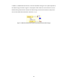
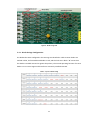
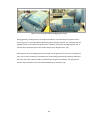
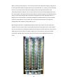
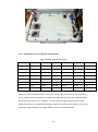
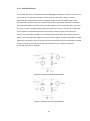
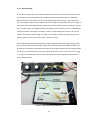
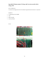
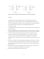
For this test, the connection was broken by slitting the wiring lining on the PCB (This was done
for all the strings). This provided an open circuit where two leads for an ammeter was soldered
in. The ammeter would be used to measure the current passing through the strings during the
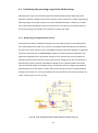
curve production. In addition, to monitor the voltage across the string, two leads was soldered
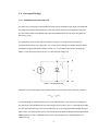
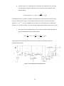
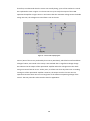
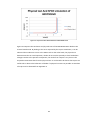
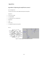
over the two points as illustrated in Figure 28.
Figure 28 - Circuit of diode strings in the test
49