1
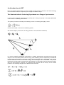
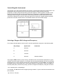
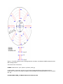
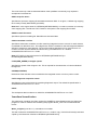
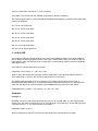
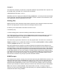
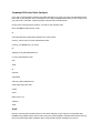
By applying the cosine rule to the scattering triangle, bearing in mind that ki is fixed and translating
into energy units, it can be clearly seen that a detector positioned at a scattering angle f will perform a
scan in time whose loci is a parabola in Q,w space.
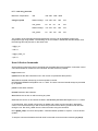
The scan performed by each detector is dictated by the scattering angle of that detector and the
incident energy.
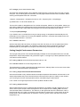
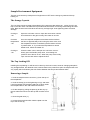
Components of a Chopper Spectrometer. The components of a chopper spectrometer such as HET are shown in the schematic diagram.
Alongside are examples of the neutron spectra at each point along the path of the neutron. The
proton pulse hitting the target produces a burst of very fast, very high energy neutrons. To slow these
down to usable energies the high scattering cross section of hydrogen is utilised. Hydrogen at 22K,
CH2 at 100K and H2O at 316K are used as moderators. In order to preserve the high flux of high
energy neutrons which is a valuable feature of pulsed sources the beam is undermoderated. That is
to say the neutron flux leaving the moderator has two components; the Maxwellian component
caused by the moderation and the epithermal (high energy flux) of the weakly moderated neutrons.
Figure 1 Schematic diagram of a chopper spectrometer.
A substantial amount of background arises from gamma rays
when the proton beam hits the target and from fast neutrons
which thermalise within the spectrometer. Consequently the
background is reduced significantly by using a nimonic chopper
which effectively closes the beam tube to the spectrometer at the
moment the proton beam is incident on the target.
The beam itself is monochromated by a Fermi chopper, which is
an aluminium drum with thin sheets of highly absorbing material
such as boron, interleaved with neutronically transparent sheets
of aluminium. The rotation of the drum is phased to the ISIS pulse
and is only in transmitting position at the point at which it will only
transmit neutrons with the desired velocity and hence ki and Ei.
In practice the slits are curved in opposition to the direction of
rotation to optimise transmission. The chopper drum becomes
increasingly grey as the energy increases. This greyness gives
rise to a modulated background. This has been reduced by
installing B4C cheeks in the chopper bodies, but still needs to be
accounted for when analysing data.
Monitors are located at the positions indicated on the schematic
diagram of the spectrometer. The time-of-flight between monitors
2 and 3 is used to determine the incident energy.
The sample is mounted on a variety of sample environment
including cryostats, pressure cells and furnaces all with a
standard 17" Tomkinson flange. The tank itself is evacuated to a
cryogenic vacuum during an experiment. The beam tubes and
detector tanks are evacuated to a rough vacuum thus reducing
the background arising from air scattering.
The size of the neutron beam falling on the sample is determined
by the extent to which the beam has been collimated and
apertures at the entry to the sample tank. The final aperture may
be altered by changing the final collimation piece. In the near