1
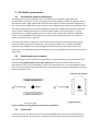
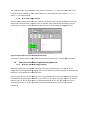
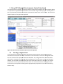
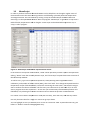
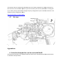
ISIS
MuSR Manual
P.J. Baker, A.D. Hillier, J.S. Lord, and S.R. Giblin
29th June 2011
Contents
1.
Introduction............................................................................................................................................. 4
2.
The MuSR spectrometer ...................................................................................................................... 5
2.1
Instrument features and layout ....................................................................................... 5
2.2
Rotating the spectrometer ................................................................................................ 5
2.3
Interlocks .............................................................................................................................. 5
2.3.1
Closing the area ..................................................................................................................... 6
2.3.2
Opening the area .................................................................................................................. 6
2.4
Muon beam ........................................................................................................................... 7
2.4.1
Rate, spot size, and slit positions .................................................................................... 8
2.4.2
Frequency response .......................................................................................................... 10
2.4.3
Range curve .......................................................................................................................... 10
2.5
Magnets ............................................................................................................................... 11
2.5.1
Main magnet ......................................................................................................................... 11
2.5.2
Calibration coils .................................................................................................................. 11
2.5.3
Zero field compensation .................................................................................................. 12
2.6
Detectors and Data Acquisition Equipment................................................................. 12
2.6.2
Data Acquisition Equipment .......................................................................................... 13
2.6.3
3.
Computers available ......................................................................................................... 13
Using SECI (Sample Environment Control Interface) ............................................................. 14
3.1
Loading configurations .................................................................................................... 14
3.2
SECI/OpenGENIE commands........................................................................................... 15
3.3
MuonScript ......................................................................................................................... 16
4. Sample Environment .......................................................................................................................... 18
4.1
Oxford Instruments Variox cryostat ............................................................................. 19
4.1.1
Setting up and changing sample ................................................................................... 19
4.1.2
High and low-temperature mode operation ............................................................ 19
4.1.3
Boost mode ........................................................................................................................... 20
4.2
Oxford Instruments Variox (Beast) ............................................................................... 21
4.2.1
Setting up and changing sample ................................................................................... 21
4.2.2
4.3
4.4
4.5
4.6
High and low-temperature mode operation ............................................................ 22
TBT dilution fridge ........................................................................................................... 23
Oxford Instruments dilution fridge ............................................................................... 23
Sorption refrigerator........................................................................................................ 24
Furnace................................................................................................................................ 24
4.7
CCR ....................................................................................................................................... 24
4.8
Small flow cryostats .......................................................................................................... 25
4.9
Long flow cryostat ............................................................................................................. 26
5. Data analysis.......................................................................................................................................... 27
5.1
Accessing the data ............................................................................................................. 27
5.2
Dashboards......................................................................................................................... 27
5.3
Data analysis software ..................................................................................................... 27
6. Further information ........................................................................................................................... 28
6.1
ISIS User Office (Transport, accommodation) ............................................................. 28
6.2
Food ..................................................................................................................................... 28
6.3
Contact numbers ............................................................................................................... 28
6.4
Connecting a laptop computer ....................................................................................... 28
6.5
Site map............................................................................................................................... 29
Appendices...................................................................................................................................................... 29
A.
Pulsed techniques that can be used with MuSR ........................................................................ 29
7.
Troubleshooting................................................................................................................................... 30
7.1 No muons (or very few muons)............................................................................................ 30
7.2 Counting, but strange data .................................................................................................... 30
7.3 Temperatures.......................................................................................................................... 30
8. Quick Guide to SECI ............................................................................................................................. 32
List of Figures
Figure 1: MuSR in its longitudinal and transverse orientations.............................................................. 5
Figure 2: Interlock key box, master switch, and main door lock. ........................................................... 6
Figure 3: A muon beam off button ......................................................................................................... 7
Figure 4: Layout of the muon beamlines ................................................................................................ 8
Figure 5: Graph of asymmetry and rate vs slit position. ......................................................................... 9
Figure 6: Frequency response in MuSR................................................................................................. 10
Figure 7: Range curve for the Blue Variox Cryostat. ............................................................................. 11
Figure 8: Zero Field vi in active compensation mode. .......................................................................... 12
Figure 9: MuSR detector numbering..................................................................................................... 13
Figure 10: SECI dashboard with the Open Genie tab displayed. .......................................................... 14
Figure 11: MuonScript window with representative entries. ............................................................... 16
Figure 12: Range curve for Beast Variox Cryostat. ............................................................................... 21
Figure 13: Site map of RAL. ................................................................................................................... 29
1. Introduction
This manual is designed to provide all the basic information needed to perform an experiment using
MuSR. If there is anything you remain unsure about you should check the details with your local
contact or one of the instrument scientists.
Before starting to collect data it is worthwhile to check the following things are set up as desired:
•
•
•
The instrument geometry (longitudinal or transverse) described in section 2.2.
The spectrometer area has been cleared of personnel, the interlocks have been set correctly,
and the beam blocker has been raised to allow muons through to the sample. The
procedures for doing this are explained in section 2.3.
The magnetic field is correct for:
a) Compensation of the Earth’s magnetic field,
b) Calibrations,
c) Measurements.
The procedures for setting the magnets are described in section 2.5.
•
•
•
Sample environment is working as expected (section 0).
The beam slits and steering are chosen to match the size of the sample and the desired
event rate. This is described in section 0.
The data acquisition and analysis software have been set up correctly. These are described
in sections 0 and 0, respectively.
This manual also includes the details of how to access and analyse the data recorded (section 0) and
information for ISIS users (section 0). At the end of the manual are the troubleshooting section and a
brief guide to commonly used SECI commands.
2. The MuSR spectrometer
2.1
Instrument features and layout
The MuSR spectrometer has 64 detectors, each comprising a scintillator, light guide, and
photomultiplier tube (PMT). These are arranged in two rings facing each other on opposite sides of
the sample position. High-voltage cables take the PMT signals to the data acquisition equipment in
the rear of the instrument cabin. There are three sets of magnets that can be used with MuSR: fixed
zero-field compensation coils, the main magnet producing up to 2500G, and removable calibration
coils to produce fields perpendicular to the main magnet. Next to the spectrometer is a small
platform which is needed to guide cryostats in and out of the spectrometer when in longitudinal
mode. A set of stepladders is provided for this purpose when the spectrometer is in transverse
mode, or if further access is required.
The instrument cabin has computers for controlling the spectrometer through the SECI program,
monitoring the progress of the experiment, and carrying out data analysis. Samples should be
mounted in the prep lab across the loading bay from the instruments and cabins towards the
synchrotron. Any sample preparation should be done on a tray labelled with one of the forms kept in
the lab door.
2.2
Rotating the spectrometer
The spectrometer can be rotated from longitudinal to transverse mode in around 30 minutes. This
procedure must be done with a local contact present to move the cryostat in and out of the
spectrometer and to ensure no damage is done to the spectrometer or any of the apparatus within
the area. A list of people authorized to supervise the spectrometer rotation is displayed on the fence
of the spectrometer area.
Figure 1: MuSR in its longitudinal and transverse orientations.
2.3
Interlocks
In order to ensure the safety of personnel around the MuSR spectrometer the muon beam has a
series of interlocks that prevent muons entering the spectrometer area whilst people have access.
This section describes the procedures for exiting and entering the MuSR area under normal
operating conditions. Some pulsed techniques such as Radio Frequency µSR have a further series of
interlocks that are explained in their appendix to this manual.
Figure 2: Interlock key box, master switch, and main door lock.
2.3.1 Closing the area
To leave the MuSR spectrometer area:
1. Close the gate which allows access above the spectrometer on the top of the MuSR
platform, remove its key and insert into the key box to the right of the lower area door. Turn
the key clockwise. (The locking pins need to be in the vertical plane for the lock to be shut
and can be easily adjusted if they have misaligned.)
2. Check that no-one is inside the MuSR area. Press the search button (situated on the far side
of the spectrometer) and close the area door and remove the key from the lock (turning
anticlockwise). Insert this key into the key box to the right of the door, turning it clockwise.
3. The key box should now be full.
4. The blocker can now be raised: press the raise button next to the small red light bulb and
keep it pressed until the blue area lights come on and the blocker has stopped moving.
2.3.2 Opening the area
To enter the MuSR spectrometer area:
1. Check that the magnetic fields applied on the instrument are compatible with safe entry to
the area. It is necessary to switch off the main magnet and calibration coils when changing
cryostats.
2. Lower the blocker by pressing and holding the green button. The white area lights come on
once the blocker is down.
3. Remove the topmost available key from the key box by turning it anticlockwise and insert it
into the door lock, turning clockwise. (There is no longer a separate bolt.)
4. The door can now by opened by removing the locking bolt.
5. If it is necessary to open the gate on the MuSR platform, remove the topmost key from the
key box and use it in the gate lock.
2.3.3 Muon beam off buttons
In an emergency the muon beam can be immediately switched off by pressing a muon beam off
button such as that pictured below. If this happens you should inform your local contact, who will be
able to reactivate the beam once the emergency has been rectified.
Figure 3: A muon beam off button
2.4
Muon beam
MuSR receives the second of the two pulses of surface muons that come from the muon target
every time the ISIS synchrotron sends protons towards the neutron target. Before it reaches the
spectrometer it is focused and steered to control where the muons hit the sample in the cryostat.
This is done using a combination of dipole and quadrupole magnets that are shown in the figure
below. The focussing and steering of the muon beam will have been checked during the calibration
period at the start of each ISIS cycle. If a change to the focussing or steering is required for your
experiment you should speak to your local contact. The two pulses of muons that travel from the
muon target are separated using an electrostatic kicker before the EMU and HiFi beamlines branch
off from the MuSR beamline. This uses a large DC voltage to split the first of the two bunches of
muons so they can be steered into EMU and HiFi.
Figure 4:: Layout of the muon beamlines
2.4.1 Rate,, spot size, and slit positions
The count rate is controlled by varying the number of muons entering the spectrometer in each
bunch. This is done
ne using a variable slit just downstream of the electrostatic kicker that changes the
size of the muon beam spot.. We can estimate the size of the muon spot by placing different sized
discs of hematite on a silver backing plate and changing the slit positions.
positions. Muons stopping in the
hematite contribute a negligible amount to the asymmetry signal because they are rapidly
depolarized whereas those stopping in the silver remain fully polarized. The resulting asymmetry and
rate curves are plotted against slit position
pos
in the graph below.
Figure 5: Graph of asymmetry and rate vs slit position.
It is best to choose a fixed slit position for a given experiment to provide the most consistent results.
If small samples are being measured it may be desirable to close the slits below the position giving
the optimum rate. Otherwise, it is best to open the slits to a level just below the point at which the
data become distorted by the effects of detector deadtime (recovery after counting a positron) and
buffer overflow in the electronics. Such problems are evident in a drop in the count rates in each
detector that recovers exponentially at short times. With the present instrument set-up the optimal
counting rate is 40-45 MEv/h. The choice of slit position to achieve this varies with the cryostat used.
2.4.2
Frequency response
Because the bunch of muons arriving in the sample do not arrive at the same instant, any transverse
fields within the sample cause the muons to precess relative to each other during the period they
enter the sample. The result of this is that the asymmetry of precession signals decreases as a
function of the transverse magnetic field, as can be seen in the figure below. The same effect applies
to oscillations due to fields inside samples and also to relaxation rates, and places a limit on what
can be measured using ISIS muon instruments.
Figure 6: Frequency response in MuSR.
2.4.3 Range curve
It is very important that the muons stop in the sample rather than in the mount or cryostat. Getting
this right can be achieved by examining the range curve. For the Variox cryostat the range curve is
shown in figure (number). The aim is to have the sample centre at the midpoint of this curve. To
adjust the stopping range silver, titanium, or mylar sheets can be placed in front of the sample. The
best approach can be discussed with your local contact.
Figure 7: Range curve for the Blue Variox Cryostat.
The range curves are different for each cryostat and those which are significantly different from the
Variox curve shown here are included in the sections for each cryostat.
2.5
Magnets
The MuSR spectrometer has three sorts of magnets acting on the sample position: zero field
compensation coils, calibration ‘T20’ coils, and the Helmholtz coils that act as the main magnet. They
are set to act individually through the SECI program.
2.5.1 Main magnet
The main magnet can be used to provide up to 2500G in longitudinal mode and around 600G in
transverse mode (limited by the frequency response).
To switch on the main magnet use the SECI command lf0. SECI should write “Danfysik power
supply has been selected”. After this commands of the form setmag nn, where nn is the desired
field, can be used to set the field.
2.5.2 Calibration coils
The calibration coils are used when the spectrometer is in longitudinal mode to provide a small
transverse to calibrate the difference in count rates in the forward and backward detectors. They
hang from flexible hooks next to the cryostat space and have a power cable leading from the
downstream wall of the spectrometer area. When inserting them, before putting the cryostat into
the spectrometer, check that they are facing in the correct direction – shown by the Out labels
painted on the coils.
The calibration coils are switched
ched on using the SECI command tf20,, which also sets 20G. This is
normally ideal for calibration, but smaller fields can be set using commands such as setmag nn
where nn is the desired field.
2.5.3 Zero field compensation
The zero field compensation coils work in active combination with a flux gate probe to ensure the
field at the sample position is reduced as far as possible. After calibration before each cycle the
compensation process is controlled within SECI and can be viewed from the Magnets screen.
Figure 8:: Zero Field vi in active compensation mode.
To switch on the zero field compensation use the SECI command ‘f0’ in the OpenGENIE window.
2.6
Detectors and Data Acquisition Equipment
2.6.1
Detector positions and grouping
gro
MuSR has 64 detectors arranged in two rings around the sample position. In order to form a
longitudinal forward-backward
backward grouping, detectors 33-64
33 64 are summed to form the forward set, and
detectors 1-32
32 summed for the backward set.
In the transverse case,
ase, the two detector arrays are perpendicular to the initial polarisation direction.
A suitable way of grouping the detectors in this case is in four groups of eight: top (17-24
(17
+ 49-56),
bottom (1-8 + 33-40),
40), forward (9-16
(9
+ 57-64) and backward (25-32 + 41-48).
48). These sets can be
analysed separately, or further arranged into forward-backward
forward
sets (top-bottom,
bottom, forwardforward
backward).
Figure 9:: MuSR detector numbering. Detector 33 is on the far bottom corner from detector 1.
2.6.2 Data Acquisition Equipment
The Data Acquisition Equipment is kept in the instrument cabin.
2.6.3 Computers available
Three computer screens are permanently installed in the MuSR cabin. The screen on the right-hand
right
side of the cabin nearest the DAE is used for running
running SECI to control the instrument (MUSR). This is
mirrored on a screen on the muon area platform. The screen in the middle of the cabin shows the
status of the experiment and control parameters on the instrument dashboard. The screen on the
left is used for
or data analysis and has a number of suitable programs installed on the attached
computer (MUSR01).
Power sockets (UK and EU) are available for laptops and Ethernet cables and sockets are available if
the wireless signal proves inadequate. Further information
information on this is provided in Section 6.4.
3. Using SECI (Sample Environment Control Interface)
The data acquisition, magnets, and all the sample environment equipment that are involved in doing
an experiment using the MuSR
R spectrometer are controlled using the SECI program. A brief guide to
the most commonly used SECI commands is printed on the back cover of this manual. Here the more
detailed aspects of using SECI are explained.
explained
Figure 10: SECI dashboard with the Open Genie tab displayed.
3.1
Loading configurations
To use any piece of sample environment with SECI it needs to load the control and monitoring
information for that piece of sample environment. This information is stored in configuration files
f
that are saved after the equipment has been calibrated. The configuration files are loaded either
when SECI is restarted or by selecting “Open
“
Configuration” from the menu
u at the top of the SECI
window. This should be carried out with your local contact
contact when there is a change to new sample
environment. Those cryostats that have more than one centre stick will have a configuration for
each stick and it is important to change these appropriately (temperature control and monitoring
relies on this).
3.2
SECI/OpenGENIE commands
Experiments are normally controlled by typing commands into the Open Genie command line
window on the Dashboard page in SECI. Commands are not case sensitive.
BEGIN
END
PAUSE
RESUME
LF0
SETMAG value
F0
TFCAL
SETTEMP value
Starts a run. Asks for a sample name and other details. The temperature and
field entered here are used only for the file header, and do not set anything.
Finishes and saves a run. There is a last chance to change the header details.
Pauses data acquisition
Resumes data acquisition
Selects the main magnetic field (initially set to zero)
Sets the magnetic field to the specified value in Gauss.
Sets zero field using the Hall probes and X,Y and Z coils. This is a one-off
adjustment each time F0 is typed, not continuously monitored as on MuSR.
Selects the transverse Y coil and sets it to 100G for calibration. Other values
can then be set if required.
Sets the temperature on the cryostat/CCR/furnace – usually in K
The SETTEMP command also sets the appropriate control parameters – heater power, P,I,D values,
and for scripts the required stability before a run begins. These are selected from a table which can
be viewed by choosing the “TPAR” blue menu entry. You can edit the table and then do “FileUpdate” and the new values will be used on the next SETTEMP command or temperature change in
a script. If you change configurations the default table for the sample environment equipment
chosen is reloaded.
The header details can also be changed at any time before the run ends using the SETLABEL
command, which will ask for the new value.
SETLABEL /S Sample name
/O Orientation
/T Temperature
/F Field
/RB RB number
/U Users
/C Comments
In addition to the header, various measured values such as the sample temperature and magnetic
field are logged in the run file.
The following additional commands may be needed in special cases:
END_IMMEDIATE
ABORT
BLUE_HT
BLUE_LT
BOOST
CSHOW/ALL
Ends and saves the run without waiting for the period cycle to complete. Use
only if in period mode and the beam has gone off.
Ends the run and throws away the data. Use with care!
Puts the Blue and Beast Variox cryostats into high-temperature automatic gas
valve control mode
Puts the Blue and Beast Variox cryostats into low-temperature manual gas
valve control mode
Uses the centre stick boost heater on cryostats with one
Show all control blocks (or use Display Blocks Status in SECI, see left of Fig. 9)
3.3
MuonScript
In order to produce consistent data with MuSR it can be helpful to run through a regular series of
measurements with the same counting statistics and following a planned pattern of temperature
and magnetic fields. This can be done by writing a script in the MuonScript
M
Script window of SECI and
executing it in the OpenGENIE window. We use a program “MuonScript”
Script” to generate a script from a
table of fields, temperatures and run lengths. A new script can be edited while a previous run, or
script, is still in progress.
Figure 11:: MuonScript window with representative entries.
entr
In the menu on the top left of the window, “Read” allows previously written scripts to be opened for
editing, “Write” saves the currently written script, and “Clear Script”” empties the current contents of
the MuonScript window.
To add an entry, type in
n the required temperature, field (selecting main longitudinal field or
calibration), and number of million events (MEv), then click “Add”. If no change is required leave the
temperature and/or field values blank, instead of re-entering
re
the same value – this
th avoids having to
wait to confirm the value is still stable. The first entry can take control of, and finish off, a run that
was in progress when the script starts – in this case you would usually leave both temperature and
field blank, only selecting thee number of million events at which the present run should finish.
finish
For a linear scan of either temperature or field (but not both), enter the start, end and step values.
Use only the Start value for a single run. Scans can go up or down.
You can highlight an entry in the table, then “Insert At” instead of “Add” to place
lace the new entry just
before it. “Delete” removes thee highlighted entry.
entry
To estimate the counting time taken by a script, enter the count rate in the box at the bottom left,
and MkScript will calculate the total counts in the script and the estimated time. This does not
include time for temperature or field changes which may be significant. (To update the estimated
time after changing the rate, add another entry, or click somewhere in the table.)
Finally save the script with “Write” and choose a filename for it.
To load a script that has been edited, go to the OpenGENIE window and type:
load “yourscriptname.gcl”
using the filename you chose. (As a reminder the name is shown in the bottom border of the
MuonScript window, and you can also use Tab to auto-complete the name.)
Note that the script will not set (or prompt for) the sample name or any header entries other than
the temperatures and fields it actually sets. If you are about to start measurements on a new sample
using a script, use the SETLABEL command to ensure the sample name, etc. are correct. If you have
just set a temperature or field the script will not put this in the header either – again use SETLABEL.
Finally, type runscript to start the script.
When a script changes temperature, the TPAR parameters “Accuracy”, “Wait” and “Timeout” for the
new set point are used. The control temperature readback must be within (Tset ± Accuracy)
continuously for the Wait time (in minutes), before the next run starts. No check is made on the
sample log temperature; the “Wait” must be long enough to allow it to come to equilibrium. For
very large samples Wait may have to be increased. If the temperature is not stable after Timeout
(minutes), even if it had just reached the set point and the Wait interval is now counting down, the
run starts anyway.
To stop a script:
Ensure the OpenGENIE window is active and press Ctrl-C. There may be a message about “wait
cancelled” then the prompt returns. If a run was in progress it will still be running and will not stop
at the number of events specified in the script – use end to stop it when appropriate. Alternatively
you might write a new script, or edit the old one, to complete this run and continue.
To pause a script during a run (for example while closing the blocker and entering the area) go to the
OpenGENIE window and type pause. To resume the run type resume. This will avoid accumulating
empty frames which will upset the dead time calculations.
4. Sample Environment
The following sample environment is available to be used on the MuSR spectrometer. The choice of
sample environment is normally confirmed with the local contact at least several weeks before the
experiment is run. It will then be prepared by the ISIS Sample Environment group and will be ready
for the start of the experiment. Cryostats working below 1K require some preparation by the user
before the beam time starts as is explained in their sections below.
Equipment
Oxford Instruments Variox
Oxford Instruments Variox
TBT Dilution Fridge
Oxford Instruments Fridge
Sorption refrigerator
Furnace
CCR (coming soon)
Small flow cryostat
Long flow cryostat
Schedule code
OXF/MuSR
OXF/Beast
DR/TBT
DRI/MuSR
SR/Mu
Fur/Mu
CCR/MuSR
FLO/HiFi
Temperature range
1.5 – 300 K
1.5 – 300 K
0.04 – 4 K
0.04 – 4 K
350 mK – 50 K
300 – 1000 K
TBC
5 – 600 K
4 – 300 K
Manual Section
4.1
4.2
4.3
4.4
4.5
4.6
4.7
4.8
4.9
As well as preparing the cryostats before an experiment the ISIS Cryogenics group does their best to
keep them topped up with cryogens while experiments are running. Nonetheless, it remains the
users’ responsibility to check that the levels are sufficient, particularly when large temperature
changes or sample changes have occurred, and if leaving the experiment unattended for any period.
Rapid consumption of cryogens is often a symptom of a malfunctioning cryostat! Information on
cryogen levels is usually presented on the instrument dashboard (section 5.2) or in SECI. Otherwise
the level gauges connected to the cryostats can be read directly.
4.1
Oxford Instruments Variox cryostat
SECI Configuration Names
Blue_itc502, Blue_itc502_Boost, Blue_itc503,
Blue_itc503_Boost
OpenGENIE Commands
blue_lt (Operation below 4.5K)
blue_ht (Operation above 4.5K)
boost (Allows use of boost heater)
The range curve for this cryostat is shown in Figure 7.
4.1.1 Setting up and changing sample
The cryostat will be craned into place by your local contact and the necessary electrical connections
made. The ISIS sample environment group will endeavour to maintain suitable cryogen levels during
your experiments but it is important to check that it contains sufficient cryogens before leaving it
unattended for any period. Both helium and nitrogen levels should be monitored.
Removing a sample
1. Ensure the cryostat temperature is greater than 25 K; too low a temperature, and any liquid
helium that has been pulled through the capillary could boil rapidly; too high a temperature could
cause He gas to diffuse through the Mylar window into the outer vacuum space.
2. Ensure the cryostat is connected to the He return panel, or that a non-return valve is fitted to the
He outlet (7).
3. Close the valve to the pump on the capillary line (13).
4. Fill the sample space with He by turning black 3-way valve (8) downwards. Wait until the flow
meter on the He return line registers flow again.
5. Remove the sample stick quickly but smoothly by undoing the Klein flange. Cover the sample
space with the blanking flange. Return the 3-way valve (8) to its horizontal position.
6. If the cryostat is to be left for a time without a sample present, pump the sample volume (via the
3-way valve (8), turned to upwards position, using the rotary pump connected to the port above the
valve).
Loading a sample
1. Ensure the sample stick is completely dry before inserting it into the cryostat.
2. Ensure the cryostat is at about 25 K.
3. Ensure the cryostat is connected to the He return panel, or that a non-return valve is fitted to the
He outlet (7).
4. Fill the sample space with He by turning the black 3-way valve (8) downwards. Wait until the flow
meter on the He return line registers flow again.
5. Remove the blanking flange and introduce the sample stick quickly but smoothly (3).
6. Pump the sample space (via the 3-way valve (8), turned to its upwards position) to ~1 mbar (the
gauge on the top of the cryostat (10) reads the sample space pressure) using the rotary pump.
7. Turn the 3-way valve (8) to its downwards position to add He to the sample space, and pump
again to about 1 mbar.
8. Add He to the sample space again and pump until the sample space gauge (10) reads 20 mbar.
This is the correct exchange gas pressure.
4.1.2
High and low-temperature mode operation
For temperatures above 4.2 K the cryostat can be operated with the gas flow valve under automatic
control, having set blue_ht in the OpenGENIE window.
To achieve stable temperatures below 4.2 K it is necessary to control the gas flow valve manually.
Issue the command blue_lt in the OpenGENIE window and check that the gas flow control in the
temperature window of SECI is showing ‘Manual’. Connect the flow gauge attached to the Rootes
pump frame to the exhaust and adjust the gas flow using SECI until the exhaust flow rate is around
450cm3/min. The temperature should drop rapidly to below 2K. Small adjustments to the flow rate
may be needed to ensure a stable temperature. Ensure that the temperature can be stabilized at the
desired base temperature and disconnect the flow gauge to prevent it being clogged by oil. Set
points can be set in the conventional manner up to around 5K. To return to higher temperature
operation the blue_ht command should be issued in OpenGENIE.
4.1.3
Boost mode
Boost mode is used to speed up temperature changes on warming above 30K. It uses a second
temperature controller and a heater on the sample stick to achieve this. To use boost mode the SECI
configuration must include _boost and the OpenGENIE command boost must have been entered.
Boost mode does not increase cooling speed or change the operation of the cryostat below 30K.
4.2
Oxford Instruments Variox (Beast)
SECI Configuration Names
OpenGENIE Commands
Beast_itc502, Beast_itc503
blue_lt (Operation below 4.5K)
blue_ht (Operation above 4.5K)
This is similar to the other Variox cryostat but with a larger helium bath and a different sample stick.
There is no boost function on this cryostat.
Figure 12: Range curve for Beast Variox Cryostat.
4.2.1 Setting up and changing sample
The cryostat will be craned into place by your local contact and the necessary electrical connections
made. The ISIS sample environment group will endeavour to maintain suitable cryogen levels during
your experiments but it is important to check that it contains sufficient cryogens before leaving it
unattended for any period. Both helium and nitrogen levels should be monitored.
Removing a sample
1. Ensure the cryostat temperature is greater than 25 K; at lower temperature any liquid helium that
has been pulled through the capillary could boil rapidly; too high a temperature could cause He gas
to diffuse through the Mylar window into the outer vacuum space.
2. Ensure the cryostat is connected to the He return panel, or that a non-return valve is fitted to the
He outlet (7).
3. Close the valve to the pump on the capillary line (13).
4. Fill the sample space with He by turning black 3-way valve (8) downwards. Wait until the flow
meter on the He return line registers flow again.
5. Remove the sample stick quickly but smoothly by undoing the Klein flange. Cover the sample
space with the blanking flange. Return the 3-way valve (8) to its horizontal position.
6. If the cryostat is to be left for a time without a sample present, pump the sample volume (via the
3-way valve (8), turned to upwards position, using the rotary pump connected to the port above the
valve).
Loading a sample
1. Ensure the sample stick is completely dry before inserting it into the cryostat.
2. Ensure the cryostat is at about 25 K.
3. Ensure the cryostat is connected to the He return panel, or that a non-return valve is fitted to the
He outlet (7).
4. Fill the sample space with He by turning the black 3-way valve (8) downwards. Wait until the flow
meter on the He return line registers flow again.
5. Remove the blanking flange and introduce the sample stick quickly but smoothly (3).
6. Pump the sample space (via the 3-way valve (8), turned to its upwards position) to ~1 mbar (the
gauge on the top of the cryostat (10) reads the sample space pressure) using the rotary pump.
7. Turn the 3-way valve (8) to its downwards position to add He to the sample space, and pump
again to about 1 mbar.
8. Add He to the sample space again and pump until the sample space gauge (10) reads 20 mbar.
This is the correct exchange gas pressure.
4.2.2
High and low-temperature mode operation
For temperatures above 4.2 K the cryostat can be operated with the gas flow valve under automatic
control, having set blue_ht in the OpenGENIE window.
To achieve stable temperatures below 4.2 K it is necessary to control the gas flow valve manually.
Issue the command blue_lt in the OpenGENIE window and check that the gas flow control in the
temperature window of SECI is showing ‘Manual’. Connect the flow gauge attached to the Rootes
pump frame to the exhaust and adjust the gas flow using SECI until the exhaust flow rate is around
450cm3/min. The temperature should drop rapidly to below 2K. Small adjustments to the flow rate
may be needed to ensure a stable temperature. Ensure that the temperature can be stabilized at the
desired base temperature and disconnect the flow gauge to prevent it being clogged by oil. Set
points can be set in the conventional manner up to around 5K. To return to higher temperature
operation the blue_ht command should be issued in OpenGENIE.
4.3
TBT dilution fridge
SECI Configuration Names
TBT
OpenGENIE Commands
N/A
This is a stand-alone dilution fridge working from around 40 mK to 4.2 K. Users need to arrive at
least 24 hours before their beamtime to allow the sample to be mounted and cooled off-beam
before measurement. The ISIS Sample Environment group and the local contact will assist with the
sample mounting and cooling process.
4.4
Oxford Instruments dilution fridge
SECI Configuration Names
OXDF_low, OXDF_high
OpenGENIE Commands
N/A
This uses the Variox cryostat described in section 4.1 with a dilution fridge insert. This allows
temperatures from around 40 mK to 300 K. Users need to arrive at least 24 hours before their
beamtime to allow the sample to be mounted and cooled off-beam before measurement. The ISIS
Sample Environment group and the local contact will assist with sample mounting and cooling.
4.5
Sorption refrigerator
SECI Configuration Names
he3
OpenGENIE Commands
N/A
The sorption refrigerator operates between 350 mK and 50 K. Users need to arrive at least 24 hours
before their beamtime to allow the sample to be mounted and cooled off-beam before
measurement. The ISIS Sample Environment group and the local contact will assist with the sample
mounting and cooling process.
Sample mounting
1. Mount sample onto the sample blade, using the usual precautions for low temperatures and
cold finger cryostat.
2. Clean and re-grease both sides of the cone seal, then pump and rotate the sample can by 180o.
3. Put on the sorption cryostat tails and pump OVC.
Computer control
1. Change the configuration to the He3 Sorption Cryostat.
2. Ensure the vi’s in both tabs (Muon Temp Panel and He3) are running.
Condensing the He3, cooling to base
1. On the Upper ITC5, Set the Sorp temperature to 40K. Please ensure that heater 1 is selected.
2. On the Lower ITC5, Cool the 1K pot to 1.6K, as a rule the 1K pot pump pressure should be
~6mbar and the needle value ~10-12%.
3. Leave for 30minutes with the 1K Pot temperature less than 1.7K and the Sorp at 40K.
4. Cool the sorp to 4K, open the needle value to ~25%, but remember to close the needle value as
soon as it is cold. Failure to do so will result in the needle valve freezing.
5. Ensure either the high temp/low temp switch is on low temp or the heater 1or2 on the lower
ITC5 is selected. Failure to do so will reduce the He3 hold time from 30+hrs to 2hrs.
Heating and cooling above 1.6K
1. Send a set point and ensure that the high temp/low temp switch is on high temp. [CHECK]
2. On cooling back down from high temp. Send a set point and heat the sorp to 19K. The cooling
power is low and this can take a long time.
4.6
Furnace
A description of the furnace will go here.
4.7
CCR
A new CCR for MuSR will be available soon.
4.8
Small flow cryostats
SECI Configuration Names
Flow_itc502, Flow_itc503
OpenGENIE Commands
N/A
The temperature range is 4 to 400K for the normal flow cryostat and 6K-600K for the cryofurnace
flow cryostat. They are mounted in a frame that is lowered into the spectrometer from above, with
the transfer tube on the downstream side of the cryostat. The locating pin on the top flange of the
cryostat will then be on the beam window side. Use the appropriate ITC5 temperature controller for
the cryostat and connect through the patch panel. Start pumping the OVC using a turbo pump.
Connections
Cryostat sample space port to a T-connector, which is connected to He gas, gauge and rotary pump.
Cryostat heater/thermometer to ITC channel 1, the stick thermometer to ITC channel 2 (stick A) or 3
(stick B) and the transfer tube needle valve to ITC Aux. Out, through the patch panel.
Transfer tube gas outlet (at the top of the dewar leg) to the pumping box via a long plastic tube
Inserting the stick
The sample can be changed when the cryostat is cold, but heat it up to >25K first.
1. Let the sample space up to 1 atm with helium and remove the blanking plate.
2. Insert the stick: the pin on the stick flange locates into the hole in the flange on the cryostat.
3. Pump the sample space, purge with helium, repeat, and admit 15 mbar of exchange gas.
Cooling
1. Check that the PTFE sealing washer is present on the cryostat end of the transfer tube.
2. Connect the needle valve cable. Turn the ITC5 on. This initialises the valve.
3. Fully open needle valve: press & hold “Gas Auto”, then press “Raise”, keep in Manual (light off).
4. Check with your local contact that the dewar has the helium level probe installed.
5. Insert the leg of the transfer tube in the dewar. Be very careful not to bend the transfer tube. In
practice the tube will need to be almost fully inserted into the dewar before the transfer tube
can be inserted into the cryostat. Reduce pressure in the dewar as required with the red valve.
6. Put the transfer tube into the cryostat and tighten the locking nut. Turn on the diaphragm pump.
Open the valve on the pumping box. There should be a very small flow.
7. After about 5 minutes the flow should increase as liquid reaches the cryostat, beginning cooling.
8. The Green valve on the dewar should be open and the Red valve closed during operation.
9. If the cryostat is still not cooling after 20 minutes, the tube may be blocked with ice or solid air:
10. Remove the transfer tube from the cryostat and dewar. Warm both ends with the hot air gun.
Blow clean helium gas through it – use a piece of rubber tube over the cryostat end.
Removing
1. Warm the cryostat to 25K or above.
2. Ensure the needle valve on the transfer tube is open (set the ITC5 to Local, press Gas Flow and
Raise) then shut the valve on the pumping box. The pressure should rise rapidly to 1 atm. If it
doesn’t, check with your local contact.
3. The transfer line can then be removed. Be careful not to bend either of the legs. If the cryostat
will be used again during the experiment the transfer line may be left in the dewar with the
needle valve closed. Be sure to fit the protective tube over the free end of the transfer line.
4. Unplug all electrical leads from the cryostat. Close the sample space tap and disconnect the
sample space pumping line.
5. Close the OVC value and switch off and disconnect the turbo pump.
6. Remove the cryostat and frame from the spectrometer.
4.9
Long flow cryostat
SECI Configuration Names
Flow_itc502, Flow_itc503
OpenGENIE Commands
N/A
The operating range is 5 to 300 K. Helium consumption is highest when operating at low
temperature, but a small flow is used even above room temperature.
Changing sample
· Ensure the cryostat is at 50 K or higher, to prevent frozen air on the windows
· Connect the scroll pump to the sample space valve. Connect a helium gas line to the small valve
on the pump, but do not open it yet. Turn on the scroll pump, pump out the line and then close
off the pump. Open the sample space valve on the cryostat.
· Remove the clamp holding the stick into the cryostat (the stick will still be held in place by
vacuum). Disconnect the thermometer cable from the stick.
· Admit helium gas to the sample space to bring it to 1 atmosphere (use the pressure gauges and
small valve on the pump set)
· Withdraw the sample stick. Leave the O-ring on the cryostat flange.
· If the new sample is not ready yet put the blank plate on the cryostat and pump the sample
space.
· Insert the new sample stick. Check the orientation –the bolts on the cryostat flange can be used
as a guide but note that the sample pit “cage” is not quite aligned with the beam / field axis.
Tighten the clamp.
· Pump the sample space with the scroll pump. Flush with helium and pump again.
· Admit 20mbar helium exchange gas and then close the sample space valve on the cryostat.
· More gas pressure may help with low temperature operation or to prevent electrical breakdown
with RF measurements. Turn off the scroll pump when finished. It may be necessary to
disconnect the pumping line in order to close the sample pit door (or because other instruments’
users will need the pump).
· Reconnect the thermometer cable. Check it is using the appropriate channel on the temperature
controller and is reading approximately the same as the cryostat (channel 1) or cooling towards
that value for a warm stick inserted in a cold cryostat.
If using a different stick to before don’t forget to change the configuration in SECI.
To change between helium storage dewars you should ask your local contact or a member of the ISIS
sample environment team for assistance.
5. Data analysis
5.1
Accessing the data
While at ISIS the data can be accessed directly from the data analysis computer in the MuSR cabin.
To access the data remotely use the iCat portal at: http://data.isis.stfc.ac.uk. You will need to log in
with your STFC Federal ID and password. To retrieve your data click on the “My Data” tab. You will
be presented with a list of the experiments you have carried out at ISIS, which can be sorted
according to RB Number, Title, Facility, and Date.
The data can be downloaded by clicking on the experiment in the listing, which opens the Datafile
Window. This lists the data sets in the experiment. Clicking on an individual run shows the metadata
associated with the file. Runs can be downloaded by selecting them and clicking the download
button. Below the download button is a box to select all the files in the set.
There are also options to search through your data and list your data. If you wish to send a particular
location in iCat to another member of your experimental team (so they don’t have to navigate to a
particular view) then the hyperlink can be copied as it points to the current view. This works if the
person opening the link has the appropriate access permissions.
New ISIS datasets are allocated a digital object identifier (DOI) which can be referenced when the
data are published. If you require a DOI for data taken before 2011 speak to your local contact or a
member of ISIS staff.
5.2
Dashboards
A dashboard showing the status of MuSR can be monitored remotely from a web browser or WAPenabled mobile phone. Go to http://dataweb.isis.rl.ac.uk and select dashboards, then MuSR. This
shows the temperature, magnetic field, and the data acquisition system status. Run titles are
redacted.
5.3
Data analysis software
There are a number of software packages that can be used to analyse MuSR data. Their manuals can
be consulted for more information. Here are some links to them:
WiMDA:
http://www.isis.stfc.ac.uk/groups/muons/downloads/wimda-installation-notes7856.html
MANTID:
http://www.mantidproject.org/Main_Page
UDA:
See the old MuSR instrument manual.
6. Further information
6.1
ISIS User Office (Transport, accommodation)
The ISIS User Office on the ground floor of building R3, room G11, should be contacted with queries
about transport and accommodation related to your ISIS experiments.
Website: http://www.isis.stfc.ac.uk/user-office/useroffice.html
Email: [email protected]
Telephone/Fax: +44 1235 445592/+44 1235 445103
6.2
Food
Breakfast for users staying in Ridgeway House is available there. Breakfasts, lunches, and dinners are
served in the R22 cafeteria. Light lunches are also available in the R1 coffee lounge. Vending
machines are situated in the User Lounge in the Experimental Hall (R5.5), next to the entry to the
hall from the Main Control Room.
Opening times are listed on a sheet in the instrument cabin and on the ISIS User Office website:
http://www.isis.stfc.ac.uk/user-office/refreshments4424.html
6.3
Contact numbers
Here is a list of useful numbers that you might find useful. Except where stated these can be dialled
from outside the lab by preceding them by +44 (0) 1235 44.
Main control room (MCR)
6789
MuSR cabin (R55)
6135
EMU cabin (R55)
6831
HiFi cabin (R55)
6851
Experimental Areas
6338
ARGUS/RIKEN
6766
Health Physics/ Sample checking
6696
Computer support
1763 (07770858090 from outside the lab)
User Office
5592
Cosener’s House
3007 (01235 523198)
Local taxis
5592 (Ring MCR outside office hours)
Airport transportation (24hrs notice required)
5592
Further useful numbers can usually be found written on the cabin doors. Contact details for
instrument scientists can be found via the muon group website:
http://www.isis.stfc.ac.uk/groups/muons/muons3385.html
6.4
Connecting a laptop computer
When you arrive at ISIS you should be given a coupon providing the connection details to the
wireless internet at RAL. If this has not happened you should speak to your local contact. This is the
preferred method of connecting while on site and should be the simplest to use.
The wireless internet reception in the MuSR cabin is not always adequate so cable connections to
the internet are also available. Speak to your local contact if you have any difficulties in setting this
up. It is likely that you will need to change the proxy configuration of your internet connection. The
automatic proxy configuration URL is:
http://wwwcache.rl.ac.uk/proxy.pac
6.5
Site map
Figure 13: Site map of RAL.
Appendices
A. Pulsed techniques that can be used with MuSR
Some pulsed techniques such as Radio Frequency µSR can be used with MuSR. See documentation
on the Muon Group website.
7. Troubleshooting
If something appears to be wrong then users should contact their local contact for assistance.
However there are a few things that could be checked first:
7.1 No muons (or very few muons)
Is the proton beam on? Check the beam current display in the hall, and in SECI check “MCR News”
and “Beam Status”. The beam displays take a few seconds to update and the MCR might not send a
message until they have some idea what went wrong. “Base rate” used to set up the accelerator
causes a corresponding reduction in muon count rate by a factor of 32.
Did you open the shutter? The “Beam On” light over the area door, the red “shutter open” light by
the shutter control buttons, and the blue lights inside the area should be lit.
The Kicker may have tripped. This vetoes data taking in all instruments to avoid accumulating
double-pulse data or just background, turns on a flashing yellow light in the MuSR cabin, and sends
an alarm to the MCR, who should reset it. Resetting takes 5 minutes - if the beam has not returned
after this time, phone the MCR.
Has a muon “Beam Off” button been pressed? This turns off the muon beams and the white lights
come on in all the muon areas. Check if someone is locked in an instrument area, or has used the
emergency release “break-glass” bolt on the door. Anyone who is in any instrument area or
blockhouse when blue lights come on should contact the MCR after pressing the “beam off” button.
7.2 Counting, but strange data
Is your data analysis correct – the right grouping and alpha? Try with another program if in doubt.
Be sure you are looking at the correct run. “Run 0” for the run in progress is only available after a
new run has accumulated 5000 frames (about 2 minutes, if the beam is on at full current), before
then you get the previous one. When a run ends, the “Run 0” file is not updated with the final data
so for final analysis re-load the data using its run number instead. A sequence of very short runs
might not update the “Run 0” file at all.
Is the count rate too high in some detectors, causing pile-up distortion? To monitor the run in
progress, select the “DAE” page in SECI, and the “Run Diagnostics 2” tab in the DAE VI that appears.
Enter 64 in the Number of Spectra box on the right, and scroll up and down to see all the channels.
Is the magnetic field set correctly? Check in SECI.
The beam may be badly focused and missing the sample. Check the beamline and steering magnets.
The Kicker may have tripped, or is still running but at reduced voltage, and failed to veto the data.
7.3 Temperatures
If the cryostat will not cool when requested, or starts to warm when it should be at a steady
temperature:
• The cryostat has run out of helium. In the case of the flow cryostat, this means that the
attached storage dewar is empty. Was this due to repeated heating/cooling cycles or
because the flow valve was stuck open?
• The CCR compressor may have stopped. There is a reset button. If it happens again ask for
assistance, it may need refilling with more helium gas.
• The flow valve is actually closed when the controller thinks it is fully open (the ITC5
temperature controllers can sometimes get confused like this, particularly after large
temperature changes in Auto flow mode). Switch the controller’s main power off and on
again to make it reset the valve, then check it is set back to “auto” operation and re-send the
set point with settemp nn.
• The flow valve or capillary is blocked. Ask for assistance to get it unblocked.
If the cryostat/ CCR will not warm up on demand, warms rather slowly, or cools below its set point:
•
•
•
The heater protection circuits have tripped. For the ITC controller, it may say “Hot 1” or “Hot
0” on the display. Check that all the thermometer leads are plugged in, then switch off and
on again to reset. For the Eurotherm controller (CCR) there is a small “reset” button to be
pressed. The CCR also has a thermal switch on the cold head, check that the compressor is
still running especially with set points above room temperature.
The heater itself (or a lamp in the furnace) has burnt out. Ask for assistance. The CCR has to
be warmed up and withdrawn in order to replace its heater.
The helium flow valve is stuck open when the controller thinks it is shut. There will be a large
flow of gas and the pumping lines will be covered with ice. Reset the controller to close the
valve, and then re-send the set point.
If the temperature does not stabilise:
• The P,I,D parameters or maximum power are incorrect for this sample. Some adjustment
may be necessary with large samples or special centre sticks, or in the furnace.
• The wrong calibrations are being used, or the sample and control thermometers are
swapped. Is the stick connected to the correct channel on the temperature controller?
• The helium flow rate is much larger, or smaller, than intended for this temperature. Check
the flow valve. Sometimes the “auto” flow algorithm does not stabilise and it helps to set
the valve to Manual operation, this is OK for operation at a single temperature or small
changes.
• One of the thermometers is faulty or not in thermal contact with the sample stage. Ask for
assistance. Similarly the heater may be in poor thermal contact with the sample.
• The thermal cut-out switch on the CCR is operating. Is the set point too high? Is the
compressor on?
8. Quick Guide to SECI
It is important to check that SECI has the correct configuration for the cryostat, sample stick, and any
period cards are set correctly before starting to collect data. Once these are all right the following
SECI commands are often useful:
begin
Starts a run. You will be asked to enter some details for the header file. These need
to be checked and confirmed at the end of the run.
end
Finishes a run and saves the data.
abort
Finishes a run and clears the data.
f0
Switches on the zero field compensation system and the other magnets off.
tf20
Switches on the calibration coils to provide a transverse field of 20G.
lf0
Switches on the Danfysik power supply to control the main magnet.
setmag nn
Sets a magnetic field of nn Gauss. Works with either Danfysik or calibration supply.
This command doesn’t do anything if the zero field compensation system is on.
settemp nn Sets a temperature of nn.
sleep nn
Waits for nn seconds.