1
Development Kit
For the PIC® MCU
Exercise Book
USB Master
March 2010
Custom Computer Services, Inc.
Brookfield, Wisconsin, USA
262-522-6500
Copyright © 2010 Custom Computer Services, Inc.
All rights reserved worldwide. No part of this work may be reproduced or copied in any form
by any means-electronic, graphic or mechanical, including photocopying, recording, taping or
information retrieval systems-without written permission.
PIC® and PICmicro® are registered trademarks of Microchip Technology Inc. in the USA and in other countries.
Custom Computer Services, Inc.
proudly supports the Microchip
brand with highly optimized
C compilers and embedded
software development tools.
1
UNPACKING AND INSTALLATION
Inventory
Use of this kit requires a PC with Windows 95, 98, ME, NT, 2000 or XP. The PC must
have a spare 9-Pin Serial or USB port, a CD-ROM drive and 75 MB of disk space.
The diagram on the following page shows each component in the USB Master kit. Ensure
every item is present.
Software
Insert the CD into the computer and wait for the installation program to start. If your
computer is not set up to auto-run CDs, then select My Computer and double-click on
the CD drive.
Click on Install and use the default settings for all subsequent prompts by clicking NEXT,
OK, CONTINUE…as required.
Identify a directory to be used for the programs in this booklet. The install program will
have created an empty directory c:\program files\picc\projects that may be used for
this purpose.
Select the compiler icon on the desktop. In the PCW IDE, click Help>About and verify
a version number is shown for the IDE and PCH to ensure the software was installed
properly. Exit the software.
Hardware
Connect the PC to the ICD(6) using the USB cable. Connect the prototyping board (8)
to the ICD using the modular cable. Plug in the DC adaptor (9) to the power socket and
plug it into the prototyping board (8). The first time the ICD-U is connected to the PC,
Windows will detect new hardware. Install the USB driver from the CD or website using
the new hardware wizard. The driver needs to be installed properly before the device can
be used.
The LED should be red(1) on the ICD-U to indicate the unit is connected properly.
Run the Programmer Control Software by clicking on the CCSLOAD icon on the desktop.
Use CCSLOAD Help File for assistance.
The software will auto-detect the programmer and target board and the LED should be
illuminated green. If any errors are detected, go to Diagnostic tab. If all tests pass, the
hardware is installed properly.
Disconnect the hardware until you are ready for Chapter 3. Always disconnect the power
to the Prototyping board before connecting/disconnecting the ICD or changing the
jumper wires to the Prototyping board.
(1)
CCS, Inc.
ICD-U40 units will be dimly illuminated green and may blink while connecting.
1
ICD-U64
ICD-U64
1
2
3
4
5
6
7
8
Storage box
Exercise booklet
CD-ROM of C compiler (optional)
Serial PC to Prototyping board cable
Modular ICD to Prototyping board cable
ICD unit for programming and debugging
USB (or Serial) PC to ICD cable
Prototyping board with a PIC18F67J10 processor chip and FTDI VNC1L USB host device
(See inside front and back cover for details on the board layout and schematic)
9 AC Adaptor (9VDC)
USB Master Exercise Book
2
USING THE INTEGRATED
DEVELOPMENT ENVIRONMENT (IDE)
Editor
Open the PCW IDE. If any files are open, click File>Close All
Click File>Open>Source File. Select the file: c:\program files\picc\examples\ex_
stwt.c
Scroll down to the bottom of this file. Notice the editor shows comments, preprocessor
directives and C keywords in different colors.
Move the cursor over the Set_timer0 and click. Press the F1 key. Notice a Help file
description for set_timer0 appears. The cursor may be placed on any keyword or built-in
function and F1 will find help for the item.
Review the editor special functions by clicking on Edit. The IDE allows various standard
cut, paste and copy functions.
Review the editor option settings by clicking on Options>Editor Properties. The
IDE allows selection of the tab size, editor colors, fonts, and many more. Click on
Options>Toobar to select which icons appear on the toolbars.
Compiler
Use the drop-down box under Compile to select the compiler. CCS offers different
compilers for each family of Microchip parts. All the exercises in this booklet are for the
PIC18F67J10 chip, a 16-bit opcode part. Make sure PCH 16 bit is selected in the dropdown box under the Compiler tab.
The main program compiled is always shown in the bottom of the IDE. If this is not the
file you want to compile, then click on the tab of the file you want to compile. Right click
into editor and select Make file project.
Click Options>Project Options>Include Files… and review the list of directories
the compiler uses to search for included files. The install program should have put two
directories in this list: devices and drivers.
Normally the file formats need not be changed and global defines are not used in these
exercises. To review these settings, click Options>Project Options>Output File and
Options>Project Options>Global Defines.
Click the compile icon to compile. Notice the compilation box shows the files created
and the amount of ROM and RAM used by this program. Press any key to remove the
compilation box.
CCS, Inc.
Viewer
Click Compile>Symbol Map. This file shows how the RAM in the microcontroller is used.
Identifiers that start with @ are compiler generated variables. Notice some locations are used
by more than one item. This is because those variables are not active at the same time.
Click Compile>C/ASM List. This file shows the original C code and the assembly code
generated for the C. Scroll down to the line:
int_count=INTS_PER_SECOND;
Notice there are two assembly instructions generated. The first loads 4C into the W
register. INTS_PER_SECOND is #defined in the file to 76. 4C hex is 76 decimal. The
second instruction moves W into memory. Switch to the Symbol Map to find the memory
location where int_count is located.
Click View>Data Sheet, then View. This brings up the Microchip data sheet for the
microprocessor being used in the current project.
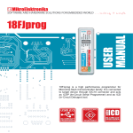
Click here for the file menu. Files and Projects are created,
opened, or closed using this menu.
Place cursor over each icon
and press F1 for help.
Compiles current selected unit, does NOT link/build
into a HEX file.
Compiles all units that have changed since last build,
links/builds into a HEX file.
Compiles all units regardless if they have changed since
last build, links/builds into a HEX file.
Click the help icon for
the help menu. The technical
support wizard and download
manager are accessed using
this menu.
Compile ribbon.
Quick view of supported devices.
Place cursor here for slide out boxes.
All of the current project’s source and
output files can be seen here.
USB Master Exercise Book
3
COMPILING AND
RUNNING A PROGRAM
Open the PCW IDE. If any files are open, click File>Close All
Click File>New>Source File and enter the filename EX3.C
Type in the following program and Compile.
#include <18F67J10.h>
#device ICD=TRUE
#fuses HS,NOWDT
#use delay (clock=10000000)
#define GREEN_LED PIN_D5
N OT E S
void main () {
while (TRUE) {
output_low (GREEN_LED);
delay_ms (1000);
output_high (GREEN_LED);
delay_ms (1000);
}
}
CCS, Inc.
The first four lines of this program define the basic hardware
environment. The chip being used is the PIC18F67J10, running at
10MHz with the ICD debugger.
The #define is used to enhance readability by referring to
GREEN_LED in the program instead of PIN_D5.
The “while (TRUE)” is a simple way to create a loop that never stops.
Note that the “output_low” turns the LED on because the other end of
the LED is +3.3V. This is done because the chip can tolerate more current when a pin is low than when it is high.
The “delay_ms(1000)” is a one second delay (1000 milliseconds).
ICD-U64
Connect the ICD to the Prototyping board using the modular cable, and connect the ICD to
the PC. Power up the Prototyping board.
Click Debug>Enable Debugger and wait for the program to load.
If you are using the ICD-U and the debugger cannot communicate to the ICD unit go to the
debug configure tab and make sure ICD-USB from the list box is selected.
Click the green go icon:
Expect the debugger window status block to turn yellow indicating the program is running.
The green LED on the Prototyping board should be flashing. One second on and one
second off.
The program can be stopped by clicking on the stop icon:
FURTHER STUDY
A
Modify the program to light the green LED for 5 seconds, then the yellow for
1 second and the red for 5 seconds.
B
Add to the program a #define macro called “delay _seconds” so the delay _
ms(1000) can be replaced with : delay _seconds(1); and delay _ms(5000)
can be: delay _seconds(5);.
Note: Name these new programs EX3A.c and EX3B.c and follow the same
naming convention throughout this booklet.
USB Master Exercise Book
4
VNC1L OVERVIEW
Introduction to the VNC1L
The Vinculum VNC1L USB Master chip allows a microcontroller to interface to other
USB devices as the bus master. The VNC1L can read and write a bulk-only mass
storage device such as flash drive, act as a limited USB hub, communicate with a printer
and communicate with CDC-class (virtual COM port) devices.
The VNC1L is a purpose-designed microcontroller made by vinculum, a subsidiary of
FTDI Chip. Vinculum produces the VNC1L and writes the firmware for its operation. The
end user does not have access to the microcontroller functionality of the chip, but rather
interacts with one of several firmware programs that may be loaded onto the chip.
The VNC1L firmware works like a DOS command prompt format. The chip
communicates through a UART with a series of commands. Some commands control
the chip itself, while others control the USB Peripherals that may be attached. Interaction
with the VNC1L may be done in two ways: 1) Commands that mimic DOS and are
designed for human interaction. 2) A programming approach that is designed for the
microcontroller to utilize.
Capabilities of the VNC1L
The VNC1L is readily capable of adding USB master functionality to an embedded sys-
tem. Any of the above mentioned functions are easily implemented, among others such
as a keyboard. The VNC1L is not however a general purpose solution; some functionality is only supported on a given USB port. This simply means that the VNC1L is a good
chip to use with an intent in mind, such as a MP3 player that utilizes a flash drive as its
primary memory. The VNC1L would probably not work as well however in a general situation, such as a USB hub controller.
Capabilities discussed for purposes of this book:
The VNC1L is an embedded USB Host/Slave SoC.
Use simple command sets to eliminate the need for detailed knowledge of USB.
Communicate with a microcontroller over UART, FIFO or SPI.
Support of two USB ports:
Port 1: Connect any FT232/FT245 Based USB Peripheral here.
Port 2: Connect a USB Flash Disk or BOMS (Bulk Only Mass Storage) device.
CCS, Inc.
Capabilities of the CCS Prototyping board:
The CCS prototyping board has a PIC18F67J10 microcontroller that is used to interface
with the VNC1L chip. The PIC18F67J10 uses the UART1 to talk to the VNC1L. The user
can talk to the PIC18F67J10 over UART2 using the Serial Port Monitor program. The
VNC1L supports two USB ports which are provided on the board.
The prototyping board also has two pushbuttons, three LEDs and one potentiometer.
The prototyping board comes with the latest VDAP (Disk and Peripherals) firmware
installed on the VNC1L chip.
The firmware on the VNC1L may be upgraded or changed to other firmware load types
over a serial interface. See Chapter 11 for instructions on bootloading.
USB Master Exercise Book
5
VNC1L CONTROL CHANNEL
The VNC1L firmware is designed to accept DOS like commands from a microcontroller.
The VDAP firmware, which is a multi purpose firmware, uses a simple command set
which eliminates the need for a detailed knowledge of USB. The CCS prototyping board
is setup in such a way that these DOS commands are transmitted serially from the PC to
the PIC18F67J10 over UART2. These commands are echoed over to the VNC1L from
the PIC18F67J10 over UART1.
Click File>New and name the file EX5.c.
Type in the following code. The include file USBMaster.h should be present in the drivers folder.
#include “USBMaster.h”
void main()
{
char c;
USBMasterInit();
fprintf(USER,”USB Master Ver 1.0”);
while(TRUE)
{
if(kbhit(USER))
{
c=fgetc(USER);
USBSerialTask(c);
}
USBMasterCallback();
}
}
While this file is open, right click inside the editor pane and select ‘Make File Project’.
This will make the current .c file the main project file and the IDE will create Project
EX5.pjt.
Connect the 9-pin serial cable from the PC to the serial jack on the prototyping board.
Click on Tools>Serial Port Monitor in the IDE.
Select the correct COM port and set the baud rate to 19200 in port configuration.
Click Compile.
CCS, Inc.
Download file to the prototyping board by selecting Program Chip> ICD. Make sure the
prototyping board is powered up and the ICD-U is still connected.
The following should print out from the Serial Port Monitor:
USB Master Ver 1.0
Ver 03.65VDAPF On-Line:
The first line is output from the PIC18F67J10 device. The second line reflects output that
the VNC1L chip sent back to the device.
Ver xx.xxVcccF On-Line:
The chip returns the firmware version (xx.xx) and the firm
ware type (Vccc)
The function USBMasterInit() will initialize the pins needed for establishing the communication link between the device and the VNC1L chip. This should be called before
any other task. USBSerialTask() is called when the user transmits any data from the
serial port to the device. The function will echo this data to the VNC1L chip. USBMasterCallback() should be called once every while loop and checks to see if the VNC1L chip
has some to transmit. This data is read by the device to determine if it can act on it and
perform specific tasks.
Use the below FWV command in the Serial Port Monitor window to see the firmware
version. Place cursor in the ASCII window and type the ASCII command:
FWV (Enter)
The following response should appear:
MAIN dd.ddAAAAA
RPRG d.ddR
D:\>
The FWV command retrieves the version of the current monitor firmware and the re-
flasher code. Other DOS commands can also be tested by using the Serial Port Monitor
window. Only the VDAP commands are supported by this firmware.
Another important command, Query Port (QP), returns the class of device that is con-
N OT E S
nected to the port.
The VDAP firmware can support FTDI Class devices (i.e. ICD-U) on both
port 1 and port 2.
BOMS class devices (i.e. flash drive) are only supported on port 2 in VDAP
firmware.
USB Master Exercise Book
6
VNC1L RESPONSES
The microcontroller is able to deal with specific responses the VNC1L device accepts
from the DOS commands. These commands utilized by the VNC1L are explained in
detail in the Vinculum Firmware User Manual.
The following table documents the Monitor Configuration Commands, which are used
to configure monitor settings like baud rate. All firmware loads will support these commands.
Short Command Set
(Hexadecimal Code)
SCS (\r)
10 0D
Switches to the shortened command set
ECS (\r)
11 0D
Switches to the extended command set
IPA (\r)
90 0D
Monitor commands use ASCII
values
IPH (\r)
91 0D
Monitor commands use binary
values
SBD.divisor (\r)
14 20 divisor 0D
Change monitor baud rate
FWV (\r)
13 0D
Display firmware version
E (\r)
45 0D
Echo ‘E’ for synchronization
e (\r)
65 0D
Echo ‘e’ for synchronization
N OT E S
Extended Command Set
Function
The use of the SCS command before entering the while {TRUE} loop
puts the VNC1L into the short command set mode which allows various API calls to be made to the device.
The short command uses binary data instead of ASCII and is convenient when the user does not need to understand the data transferred
between the PIC and the VNC1L and this mode should also be used
for sending control data.
Click File>New and name this file EX6.c. Type in the following program.
CCS, Inc.
#include “USBMaster.h”
void main()
{
char c;
USBMasterInit();
}
fprintf(USER,”USB Master Ver 1.0”);
usb_putc(“SCS\r”);
while(TRUE)
{
if(!input(PUSH_BUTTON2))
{
QuerryPortCommand();
delay_ms(100);
printf(“\n\nr”)
}
if(kbhit(USER))
{
c=fgetc(USER);
USBSerialTask(c);
}
USBMasterCallback();
}
Click Compile and download to the prototyping board.
Press Pushbutton 2. The output should read: No Device Connected for both the ports.
Disconnect the ICD-U from the PC and connect the USB cable to port 1 on the prototyping
board and disconnect the modular cable from the ICD port on the prototyping board.
The Serial Port Monitor should display the following: DD1
This indicates ‘Device Detected on Port 1’ (Lower port).
Press Pushbutton 2 again to call the QuerryPortCommand. The following should be displayed:
Port 1 Status: FTDI FT232/FT245/FT2232 Device
Port 2 Status: No device Connected
Port 2 will recognize the connected device as a FTDI Class device.
Connect a flash drive to Port 2 and press Pushbutton 2. This port should identify the device as a ‘BOMS Class Device’, which stands for Bulk Only Mass Storage Device.
USB Master Exercise Book
THUMB DRIVE LIST AND READ FILES
7
One way to access data on the a USB flash drive (Thumb Drive) is to use DOS commands.
Connect the serial PC cable to the prototyping board and connect the power supply to the
prototyping board. The Thumb Drive should be connected to Port 2 of the prototyping
board.
Open the Serial Port Monitor to view the following output on the ASCII display from the previously compiled code:
USB Master Ver 1.0
Ver 03.64VDAPF On-Line:
Device Detected P2
No Upgrade
D:\>
Type ECS to ensure that VNC1L is in extended command mode.
The last line displaying the command prompt ‘D:\>’ is used to type in commands, similarly as
on a DOS prompt.
Use the ‘DIR’ command to view the files and folders present on the flash drive.
Place the cursor inside the ASCII view window, type the command ‘DIR’ and then Enter. The
‘CD’ command allows you to Change Directory in a similar manner to the DOS command
and can be used to access various files and folders on the drive.
The root folder of this drive should contain a text file called test.txt. Type in the RD command to read the text file.
D:\>RD TEST.TXT
This command will open the file ‘TEST.TXT’ , read the text inside this file, and print it out to
the Serial Port Monitor.
The IPA command will set the monitor to ASCII mode which is more suitable for this pur-
pose. The firmware resets into the IPH (binary) mode which is its default mode. The OPR
command is used to open a file for reading and the RDF command will be used to read a
specific number of bytes. The SEK command is used seek to a specific byte position.
To read only a part of the file, use the RDF command. Specify the number of bytes from
the open file. The following command sequence is an example of how to read specific
bytes from a file:
IPA
(Enter)
OPR TEST.TXT
(Enter)
RDF 30
(Enter)
If the RDF command is issued again, the next set of characters will be read. For this
example, 30 bytes were read, so it will start reading from 31 and on.
CCS, Inc.
N OT E S
File names generated by the NVC1L must be uppercase letters, numbers and/or one of the following characters:
$% ‘-_@~`!(){}^#&
After the successful completion of a command, displayed will be a
‘D:\>’ prompt.
If a command is not recognized, then an error message will be displayed. See table below:
Common Disk Commands
Function
Extended Commands
Short Commands
List files in current directory
DIR
01 0D
List specified file and size
DIR file
01 20 file 0D
Change current directory
CD file
01 20 file 0D
Move up one directory level
CD ..
02 20 2E 2D 0D
Reads a whole file
RD file
04 20 file 0D
Delete subdirectory from current directory
DLD file
05 20 file 0D
Make a new subdirectory in the current directory.
Also specify a file date and time
MKD file
MKD file datetime
06 20 file 0D
06 20 file 20 datetime 0D
Delete a file
DLF file
07 20 file0D
Write the number of bytes specified in the 1st parameter to
the currently open file
WRF dword
data
08 20 dword 0D data
Open a file for writing or create a new file.
Also specify a file date and time
OPW file
OPW file datetime
09 20 file 0D
09 20 file 0D datetime 0D
Close the currently open file
CLF file
0A 20 file 0D
Read the number of bytes specified in the 1st parameter from
the currently open file
RDF dword
0B 20 dword 0D
Rename a file or directory
REN file file
0C 20 file 20 file 0D
Open a file for reading
Also specify a file access date
OPR file
OPR file date
0E 20 file 0D
0E 20 file 20 date 0D
Seek to the byte position specified by the 1st parameter in
the currently open file
SEK dword
28 20 dword 0D
Returns the free space available on the disk if less than 4GB
is free
FS
12 0D
Returns the free space available on disk
FSE
93 0D
Display the information about the disk if is less than 4GB
IDD
0F 0D
Display disk serial number
DSN
2D 0D
List specified file, date and time of create, modify and file
access
DIRT file
2F 20 file 0D
USB Master Exercise Book
7
THUMB DRIVE LIST AND READ FILES (CONT.)
Error Messages
Extended Commands
Short Commands
Command not recognized
Bad Command
BC
Filename or directory name not found
Command Failed
CF
No free space on disk
Disk Full
DF
Attempt to open a directory for reading or writing. Attempt to
change currently selected directory to a file
Invalid
FI
Attempt to open a read-only file for writing
Read Only
RO
A file is currently opne for writing and must be closed before this
command can be executed
File Open
FO
Attempt to delete a directory which is not empty
Dir Not Empty
NE
Firmware invalid or contains disallowed characters
Filename Invalid
FN
Firmware Upgrade file not found on disk
No Upgrade
NU
N OT E S
Reason
Additional information and description of commands can be found in
Section 6 of the Vinculum Firmware User Manual
Download from: http://www.vinculum.com/documents.html#vfwspecs
The following example will demonstrate how the PIC18F67J10 will command theVNC1L
to read a specific file on the Thumb Drive connected to Port 2. It will read a specific
number of bytes from a file when the push button is pressed. This example interacts with
the VNC1L through USBSerialTask() and the USBMasterCallback() functions.
Click File>New and enter the file name it Ex7.c.
Type in the following program and Compile.
CCS, Inc.
#ifndef USE_STRING_COMPARE
#define USE_STRING_COMPARE
#endif
#include “USBMaster.h”
void main()
{
char c;
char filename[STRING_SIZE];
int16 bytenum;
USBMasterInit();
while(TRUE)
{
if(!input(PUSH_BUTTON2))
{
printf(“\n\rEnter the filename with extension (Max Length=11)”);
get_string(filename,STRING_SIZE);
printf(“\n\r Enter Number of bytes to read:”);
bytenum = get_long();
fprintf(USER, “\n\r Reading file %s ... \n\r”, filename);
USBMasterOpenFile(filename);
USBMasterReadFile(bytenum);
}
if(!input(PUSH_BUTTON1))
{
printf(“Enter Number of bytes to read:”);
bytenum = get_long();
fprintf(USER, “\n\r Reading file %s ... \n\r”, filename);
USBMasterReadFile(bytenum);
}
if(kbhit(USER))
{
c=fgetc(USER);
USBSerialTask(c);
}
USBMasterCallback();
}
}
This example shows how to select a file to read, and specify the number of bytes to be
read from that file. The define included at the top of the file USE_STRING_COMPARE,
includes code that will light up an LED when it sees a specific character in a file that it
reads. For example, if the user file contains the character ‘#’, it will light up LED 0.
USB Master Exercise Book
8
THUMB DRIVE - WRITE FILES
The VNC1L chip also supports commands to create files and write data to the files in a
Thumb Drive with the previously listed DOS based commands.
Open the Serial Port Monitor and ensure that the prototyping board is still loaded with
previous example Ex7.c.
Use the IPA command to make sure the chip is in ASCII mode.
The command to open a file for writing or to create a new one is “OPW filename”. The
filename can be up to 11 ASCII characters (8.3 format)
The WRF command will write the specified number of bytes in the first parameter
(dword) to the currently open file.
Type the following to create and modify a file:
IPA
D:\>
OPW NEW.TXT
D:\>
WRF 11
Hello World
D:\>
Execute the Close File command (CLF) to save these changes in the file.
CLF NEW.TXT
D:\>
Use the RD command to read the new file RD NEW.TXT
Hello World
D:\>
The VNC1L is also capable of accepting key strokes being typed in and log the data to a
text file on the Thumb Drive.
Click File>New and name the file Ex8.c
Click on Compile and then Program Chip to download onto the prototyping board.
CCS, Inc.
#ifndef ENABLE_LOG_FILE
#define ENABLE_LOG_FILE
#endif
#include “USBMaster.h”
void main()
{
char c;
char filename[STRING_SIZE]= “LOG.TXT”;
USBMasterInit();
}
while(TRUE)
{
if(!input(PUSH_BUTTON2))
{
fprintf(USER,”\n\r Logging data to %s...\n\r”, filename);
USBMasterLogFile(filename);
delay_ms(100);
}
if(!input(PUSH_BUTTON1))
{
fprintf(USER,”\n\rClosing File %s\n\r”, filename);
USBMasterCloseFile(filename);
ReturnFromLogging();
delay_ms(100);
}
if(kbhit(USER))
{
c=fgetc(USER);
USBSerialTask(c);
}
USBMasterCallback();
}
Once the code starts to run, it will print out the following message:
Ver 03.65VDAPF On-Line:
Device Detected P2
No Upgrade
D:\>
The code should detect the BOMS device (Flash disk) connected to Port 2. Press push
button 2 to start the data logging process. This will create a text file LOG.TXT on the
flash disk and start saving user key strokes to the text file. After typing in a few characters, use push button 1 to stop the logging process. This will close the LOG.TXT file and
save all the changes. The ‘RD’ command can then be used to read the log file
RD LOG.TXT
Testing file logging.
D:\>
USB Master Exercise Book
9
BOOT LOADING FROM THE
FLASH DRIVE
The ability to bootload a microcontroller from a file on the flash drive provides more
flexibility and portability for field applications. A common method of bootloading a
PIC microcontroller is by using a serial interface and transmitting the hex file over
the hyper terminal.
The compiler generates various output files at compile time including a .hex file
which is the final output file that gets programmed onto the chip. The compiler generates this file in the standard Intel 8 bit hex file format and it contains address and
opcode information.
Click File>New and name the file Ex9.c.
Type in the following code.
#define USE_READ_BUFFER
#include “USBMaster.h”
#define _bootloader
#include “VNC1L_bootloader.h”
#ORG default
void main()
{
char c;
USBMasterInit();
printf(“Application Ver 1.0”);
while(TRUE)
{
}
}
if(!input(PUSH_BUTTON2))
{
fprintf(USER,”\n\rEntering bootloader...) “);
#asm
goto LOADER_ADDR;
#endasm
}
if(kbhit(USER))
{
c=fgetc(USER);
USBSerialTask(c);
}
USBMasterCallback();
Click Compile and Program Chip to download onto the prototyping board.
CCS, Inc.
Open the Serial Port Monitor and the following should appear:
Application Ver 1.0
Ver 03.65VDAPF On-Line:
Device Detected P2
No Upgrade
D:\>
In order to use the flash drive to bootload the microcontroller, rename the above source
code by clicking File >Save As, and name to Ex9_new.c
Right Click in the editor pane and select Make File Project.
Modify the source code with the following changes:
Comment out line 3 of code : #define _bootloaded
Change the Application Version to 2.0 inside the printf statement.
Click Compile. The compiler will create all the output files, including the hex file ‘ex9_new.
hex.’
Copy the ‘ex9_new.hex’ file to a flash drive.
Connect this flash drive to Port 2 of the prototyping board.
The bootloader is general purpose requiring the user to use some DOS commands to get
to the correct file on the disk. Use the ‘CD’ command to go to the folder where the hex file
is stored. If the file is stored in the root directory, then the CD command is not required.
When in the correct sub folder, use the following commands to open file for bootloading:
Use the IPA command to enter the ASCII mode. Next use the OPR command to open
the hex file to use for bootloading the microcontroller. Finally, set the monitor to the
short command mode using the SCS command. The monitor can be switched back to
extended command using the ECS command.
IPA
D:\>
OPR EX9_NEW.HEX
D:\>
SCS
>
Press pushbutton 2 for the microcontroller to start reading the Ex9_new.hex file and start
writing it to ROM. Once it has finished writing all the lines of code, it will reset the chip
and print out the new application number 2.0
USB Master Exercise Book
10
INTERFACING WITH HID DEVICES
Another feature of the VNC1L chip is the ability to interface with common HID (Human
Interface Devices) like a mouse or keypad. The VDAP firmware load does not provide
any specific commands for a HID interface being used to obtain descriptor information or
enumerate the device. Therefore, the micrcontroller uses the Send Setup Data command, followed by the descriptor packet; documented in the USB standard.
A standard setup packet consists of eight (8) bytes:
Offset
Size(bytes)
Field
0
1
bm Request Type
1
1
bRequest
Description
Bitmap describing the charateristics of the
setup packet
Specific request
2
2
wValue
Dependant on Request
4
2
wIndex
Dependant on Request
6
2
wLength
Number of bytes to follow if there is a data
stage to follow
Click File>New and name this file Ex10.c
Type in the following code:
#define HID_INTERFACE
#include “USBMaster.h”
void main (){
char c;
static int8 devicenum1=0, devicenum2=0;
static int8 devicetype1=0,devicetype2=0;
int8 report_buffer[16];
int8 *ptr;
USBMasterInit();
ptr = &report_buffer[0];
usb_putc(“SCS\r”);
(continued next page)
CCS, Inc.
(continued . . .)
while(TRUE){
if(!input(PUSH_BUTTON2)){
QuerryPortCommand();
delay_ms(100);
devicenum1 = ReadAndEnumerateP1(); //Port 1 Lower
if(devicenum1 != 0xFF){
SetCurrentDeviceCommand(devicenum1);
devicetype1 = GetHIDDescriptorReport();
}else
devicetype1 = 0;
devicenum2 = ReadAndEnumerateP2(); //Port 2 Upper
if(devicenum2 != 0xFF){
SetCurrentDeviceCommand(devicenum2);
devicetype2 = GetHIDDescriptorReport();
}else
devicetype2 = 0;
}
delay_ms(100);
if(devicetype1 != 0){
SetCurrentDeviceCommand(devicenum1);
ptr = ReadAndParseReport(devicetype1);
DisplayHIDData(ptr, devicetype1);
}
if(devicetype2 != 0){
SetCurrentDeviceCommand(devicenum2);
ptr = ReadAndParseReport(devicetype2);
DisplayHIDData(ptr, devicetype2);
}
}
}
if(kbhit(USER)){
c = fgetc(USER);
USBSerialTask(c);
}
USBMasterCallback();
Click Compile and Program Chip to download to the prototyping board.
USB Master Exercise Book
10
INTERFACING WITH HID DEVICES
(cont.)
Connect a USB mouse or keyboard to the prototyping board. Both of these devices may
be connected at the same time using Port 1 and Port 2. The VDAP firmware supports
HID class devices on both the ports simultaneously.
Use pushbutton 2 to start the enumeration process.
Click the buttons on the mouse. The corresponding LEDs on the board should light.
Open the Serial Port Monitor window and type of the connected keyboard. Verify that
N OT E S
key stokes are being echoed to the Serial Port Monitor.
CCS, Inc.
The HID_Interface.c driver file implements the translation of keyboard
data into actual ASCII data.
Example Ex10.c uses the Device descriptor to receive data from the
device.
The Set Current Device Command must be used to qualify the device
as the current active device on the port before using any command.
VNC1L also supports the Data Read Command (DRD) which is recommended for use with HID Class devices.
The DRD command will return a 0x00 followed by a Command Failed
if the device does not have any data to send.
In the case of valid data, it will first return the Data Length followed by
the actual data bytes.
11
USB PRINTER EXAMPLE
A common use for the USB Master protocol is for use with a USB printer. CCS has
developed a driver for a popular USB printer by Epson. The TM-T88IV is a Thermal
Receipt Printer that is powered using the AC-DC converter. (The USB cable is only used
for communication purposes.)
The CCS driver implements basic printer functions like sending data, feed and print, cut
paper and font manipulation. Most printers have very similar protocols and modifications
can be made to this driver to fit other printer application needs. Some printers have distinctive command sets and their specifications can be obtained directly from the printer
manufacturers.
Click File>New and name the file Ex11.c.
Type in the following code:
#define HID_INTERFACE
#define EPSON_PRINTER
#include “USBMaster.h”
void main()
{
char c;
int8 devicenum1,devicenum2;
int8 devicetype1,devicetype2;
int8 length;
int8 Mystring[]= {“CCS Proto Board + PCWH Compiler”};
USBMasterInit();
length = sizeof(Mystring)-1;
devicenum1 = 0;
devicenum2 = 0;
devicetype1 = 0;
devicetype2 = 0;
usb_putc(“SCS\r”); //Enter Short Command Set
while(TRUE)
{
(continued...)
USB Master Exercise Book
11
USB PRINTER EXAMPLE (cont.)
(...continued)
if(!input(PUSH_BUTTON2))
{
SendPrinterData(&Mystring[0], length);
TransmitPrinterStatus();
TransmitandFeed(0x9F);
TransmitandFeed(0x9F);
CutPaper();
delay_ms(200);
}
if(!input(PUSH_BUTTON1))
{
devicenum2 = ReadAndEnumerateP2(); // Port 2 (Upper)
SetCurrentDeviceCommand(devicenum2);
}
}
delay_ms(200);
if(kbhit(USER))
{
c=fgetc(USER);
USBSerialTask(c);
}
USBMasterCallback();
}
Click Compile and Program Chip to download to the prototyping board.
Connect the printer via the USB cable to Port 2. (The device will work on either port, but
this example uses Port 2).
Use Push Button 1 to enumerate the device.
Use Push button 2 to transmit data to the printer.
Use the SetFont() command to change the font style and size (See the header file EpsonTM_T88IV.h for the font options).
This printer example may be expanded to easily incorporate other Epson printers which
use the ECS/POS command set. Printers from other manufacturers may also be integrated
using some of the concepts of this driver.
CCS, Inc.
12
BOOT-LOADING THE VNC1L
The VNC1L is really a specially designed microcontroller. Vinculum offers several firmware options for the VNC1L chip and the user can select the firmware based on their
application needs.
This board operates with Vinculum firmware. In order to utilize other firmware loads
available, a serial bootloader has been provided. See example EX_VNC1L_flashes.c in
the examples directory.
Using the Serial Port Monitor Program to transmit the .ROM file to the PIC18F67J10 at
57600 baud. The new firmware will be bootloaded into the VNC1L.
VNC1L Firmware loads and features:
VDAP (disk and peripherals)--This is the most general-purpose firmware load used for
talking to USB disks, as well as USB slave devices (FT232 chips, printers, Human-interface devices).
VMSC (music)--The VNC can be interfaced with a specific SPI mp3 decoder to allow
playback of mp3 files stored on a USB disk
VDIF (disk and FTDI interface)- VDPS (disk, pc monitor and slave)--Port 2 is a USB host and port 1 is a USB slave.
Port 1 acts like a FT232 chip.
VCDC(communications device class)--connect to a CDC class USB device. Examples of
these are modems, faxes, wireless adapters.
VDFC (disk file copy)--automatically copies all files from one device to a USB disk.
USB Master Exercise Book
12
BOOT-LOADING THE VNC1L (CONT.)
Device BOMS FTDI
HID
Type
Periperal
Printer Hub
PC
Host
Monitor CDC
Port
USB
Port
1
1
1
2
1
2
1
2
1
2
1
2
VDAP
Y
Y
Y
Y Y
Y
Y
Y
Y
VDIF
Y
Y
Y
Y
VMSC
Y
Y
Y
Y
VDPS
Y
Y
Y
Y
Y Y
VCDC
Y
Y
Y
Y
Y
2
2
1
2
Y Y
Y
Y
Y
The VDAP Firmware is the most load used for most of the examples in this book. Choice
of firmware is important because it dictates which ports have available functionality.
For additional firmware examples and how to use them, go to Vinculum’s website. See
next page for references.
CCS, Inc.
Further References
Official Website:
http://www.usb.org/
(Official documentation, discussion forum, certification tools and software)
Microchip’s USBApp Note Central:
http://www.microchip.com/stellent/idcplg?IdcService=SS_GET_PAGE&nodeId=1490&filterID=404
(Microchip has written several application notes about using USB with their processors.
Also includes example firmware.)
On The Web
Comprehensive list of PICmicro
Development tools and information
www.mcuspace.com
Microchip Home Page
www.microchip.com
CCS Compiler/Tools Home Page
www.ccsinfo.com
CCS Compiler/Tools Software Update Page
www.ccsinfo.com
click: Support → Downloads
C Compiler User Message Exchange
www.ccsinfo.com/forum
Device Datasheets List
www.ccsinfo.com
click: Support → Device Datasheets
C Compiler Technical Support
[email protected]
Vinculum Home Page
www.vinculum.com
Epson Home Page
www.epson.com
®
USB Master Exercise Book
Other Development Tools
EMULATORS
The ICD used in this booklet uses two I/O pins on the chip to communicate with a small debug
program in the chip. This is a basic debug tool that takes up some of the chip’s resources (I/O
pins and memory). An emulator replaces the chip with a special connector that connects to a unit
that emulates the chip. The debugging works in a simulator manner except that the chip has all of
its normal resources, the debugger runs faster and there are more debug features. For example
an emulator typically will allow any number of breakpoints. Some of the emulators can break on
an external event like some signal on the target board changing. Some emulators can break on
an external event like some that were executed before a breakpoint was reached. Emulators cost
between $500 and $3000 depending on the chips they cover and the features.
DEVICE PROGRAMMERS
The ICD can be used to program FLASH chips as was done in these exercises. A stand alone
device programmer may be used to program all the chips. These programmers will use the .HEX
file output from the compiler to do the programming. Many standard EEPROM programmers do
know how to program the Microchip parts. There are a large number of Microchip only device
programmers in the $100-$200 price range. Note that some chips can be programmed once
(OTP) and some parts need to be erased under a UV light before they can be re-programmed
(Windowed). CCS offers the Mach X which is a stand-alone programmer and can be used as an
in-circuit debugger.
PROTOTYPING BOARDS
There are a large number of Prototyping boards available from a number of sources. Some
have an ICD interface and others simply have a socket for a chip that is externally programmed.
Some boards have some advanced functionality on the board to help design complex software.
For example, CCS has a Prototyping board with a full 56K modem on board and a TCP/IP stack
chip ready to run internet applications such as an e-mail sending program or a mini web server.
Another Prototyping board from CCS has a USB interface chip, making it easy to start developing
USB application programs.
SIMULATORS
A simulator is a program that runs on the PC and pretends to be a microcontroller chip. A
simulator offers all the normal debug capability such as single stepping and looking at variables,
however there is no interaction with real hardware. This works well if you want to test a math
function but not so good if you want to test an interface to another chip. With the availability of low
cost tools, such as the ICD in this kit, there is less interest in simulators. Microchip offers a free
simulator that can be downloaded from their web site. Some other vendors offer simulators as a
part of their development packages.
CCS Programmer Control Software
The CCSLOAD software will work for all the CCS device programmers and replaces the
older ICD.EXE and MACHX.EXE software. The CCSLOAD software is stand-alone and
does not require any other software on the PC. CCSLOAD supports ICD-Sxx, ICD-Uxx,
Mach X, Load-n-Go, and PRIME8.
Powerful Command Line Options in Windows and Linux
· Specify operational settings at the execution level
· Set-up software to perform, tasks like save, set target Vdd
· Preset with operational or control settings for user
Easy to use Production Interface
· Simply point, click and program
· Additions to HEX file organization include associating comments or a graphic image
to a file to better ensure proper file selection for programming
· Hands-Free mode auto programs each time a new target is connected to the programmer
· PC audio cues indicate success and fail
Extensive Diagnostics
· Each target pin connection can be individually tested
· Programming and debugging is tested with known good programs
· Various PC driver tests to identify specific driver installation problems
Enhanced Security Options
· Erase chips that failed programming
· Verify protected code cannot be read after programming
· File wide CRC checking
Automatic Serial Numbering Options
· Program memory or Data EEPROM
· Incremented, from a file list or by user prompt
· Binary, ASCII string or UNICODE string
CCS IDE owners can use the CCSLOAD program with:
· MPLAB®ICD 2/ICD 3
· MPLAB®REAL ICE™
· All CCS programmers and debuggers
How to Get Started:
Step 1: Connect Programmer to PC and target board. Software will auto-detect the
programmer and device.
Step 2: Select Hex File for target board.
Step 3: Select Test Target. Status bar will show current progress of the operation.
Step 4: Click “Write to Chip” to program the device.
Use the Diagnostics tab for troubleshooting or the ccsload.chm help file for additional assistance.
Push
Button
1 B0
Push
Button
2 D6
LED D5
LED D1
LED D0
B5
B1
VDD
Power
9V DC
Pot A0
B4
B2
VDD
C5
C4
A1
A2
PIC18F67J10
C1
C0
PIC18F67J10
C3
C2
F4
G
G
Jumper for powering
up USB devices.
F6
ICD
Connector
RS - 232
G1, G2
USB Port 1, 2
Lower = 1