1
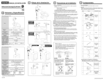
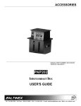
CAD drawing data catalog
is available.
ACTUATORS GENERAL CATALOG
SLIDE TABLES B TYPE
Features
Specifications
Order Codes
Allowable Bending Moment and Displacement
Dimensions
Handling Instructions and Precautions
Caution
1007
1009
1010
1011
1012
1014
Before use, be sure to read the “Safety Precautions” on p. 57.
1006
RT SLIDE TABLES (B TYPE)
CONTENTS
More precision
We have added advanced positioning precision and high rigidity
to the pneumatic actuator.
The Koganei Alpha Series further enhances the drive module
concept, supporting superior applications and labor savings in
FA line design and manufacturing with higher performance.
SLIDE TABLES
(B TYPE)
A proven and reliable slit ●
type rodless cylinder achieves
high-speed operation and longer
strokes.
● Linear guide ensures excellent
linearity and heavy load capacity.
● Space-saving design reduces
piping and wiring connections
by concentrating all the piping
and wiring in a single plane.
Magnets for sensor switch ●
are standard equipment.
● Adjustable shock absorber that improves
repeatability at the end of the stroke, enables fine
stroke adjustment, and reduces shocks and noise,
is optional equipment.
● A speed controller with quick fitting is
standard equipment.
1007
Compact sensor switch ●
can be mounted in any
required position, facilitating
detection at the end of the
stroke or in intermediate
positions.
● T-slots with built-in square nuts
that improve the versatility and
ease of mounting are placed in
2 rows along the bottom of the
body, and in 1 row each on either
side of the body.
Cylinder offers reliability,
high-speed operation, and
longer strokes.
The actuator uses a highly reliable slit type
rodless cylinder. Standard type offers long
strokes of up to 1200mm (with bore size of
φ25 [0.984in.]). Moreover, a fast operating
speed range of 200 ∼ 1000mm/s [7.9 ∼
39.4in./sec.] brings about a highly effective
system with faster cycle time.
Adjustable shock absorber which
enables high-speed operation is
optional equipment.
Concentrated placement of
piping and wiring offers
space-saving design.
The repeatability at the end of the stroke has
been further improved, and an adjustable
shock absorber that greatly reduces shock
and noise is optional equipment.
The air piping connection port and the wiring
outlet for the sensor switch are concentrated
on a single plane, while a speed controller with
quick fitting is standard equipment, for compact
piping and wiring that allows rational spacesaving equipment design.
High precision linear guide
offers heavy load capacity
and high linearity.
High precision linear guide is installed within
a flat and compact body. Responds to large
loads and bending moment to ensure high
linearity.
Instantly and easily
responds to more flexible
and accurate drive controls.
Because built-in magnets for sensor switch are
standard, mounting a sensor switch in a
required position is all that is needed to enable
detection at the end of the stroke or intermediate position.
Applicable sensor
switches (In any of
switches □4 mm
[0.157in.])
Model
Type
Indicator lamp
Voltage
ZC130□ Solid state type Available DC10∼28V
T-slot with built-in square nuts
ZC153□ Solid state type Available DC4.5∼28V
Not
DC5∼28V
CS5T□ Reed switch type
available AC85∼115V
CS11T□ Reed switch type Available DC10∼28V
1008
RT SLIDE TABLES (B TYPE)
The Alpha Series RT slide table installs a proven slit type rodless cylinder and linear guide
within a slim, thin-type body. This high-performance actuator offers superior positioning
accuracy, linearity, and heavy load capacity.
RT SLIDE TABLES
Specifications
Model
Item
Bore size
mm [in.]
ARTB16
ARTB25
16 [0.630]
25 [0.984]
Double acting type
Operation type
Air
Media
Operating pressure range
MPa [psi.]
Proof pressure
MPa [psi.]
Operating temperature range
Operating speed range
Cushion
Lubrication
1.2 [174]
0∼60 [32∼140]
°C [°F]
200∼1000 [7.9∼39.4]
mm/s [in./sec.]
Variable cushion (Strokeφ16 : 6mm [0.236in.], φ25 : 17mm [0.669in.])
Standard
Shock absorber
Option
Not required
Cylinder portion
Required (Lithium soap-based grease)Note1
Guide portion
Repeatability
mm [in.]
ParallelismNote2
mm [in.]
Stroke adjusting range
0.15∼0.8 [22∼116]
mm [in.]
N [lbf.]
Maximum load capacityNote3
Applicable tube size for speed controller
±0.05 [±0.002]
0.2 [0.008]
−22∼0 [–0.866∼0]
(To the specified stroke, 11 [0.433] on each side)
−26∼0 [–1.024∼0]
(To the specified stroke, 13 [0.512] on each side)
196.1 [44.1]
294.2 [66.1]
φ4
φ6
Notes: 1. Apply lithium soap-based grease on the raceway surface of the track rail every 6 months or every 300km [186mi.] of traveling distance.
2. This is the parallelism between the table’s upper surface and the bottom surface of the body. It is not the same as the traveling parallelism.
3. This shows the maximum load capacity values with the installation of shock absorbers. For details, see the shock absorber capacity graph on p.1011.
Shock Absorber Specifications
Item
Model
Applicable cylinder
Maximum absorption
Absorbing stroke
Maximum impact speed
Maximum operating frequency
J [ft·lbf]
ARTB25
2.9 [2.14]
5.9 [4.35]
mm [in.]
10 [0.394]
1000 [39.4]
cycle/min
30
15.7 [3.53]
9.2 [2.07]
3° or less
Angle variation
1009
ARTB16
mm/s [in./sec.]
Spring return force (At the retracted position) N [lbf.]
Operating temperature range
KSH8×10C-S
KSH6×10-S
°C [°F]
0∼60 [32∼140]
Order Codes
ART
B
16 × 500
B type
Bore size
×
Stroke
Alpha series
RT slide table
−
−
−
−
Mounting brackets
Blank : No foot mounting bracket
1A : With 2 foot mounting brackets
Number of sensor switches
1:With 1 sensor switch
2:With 2 sensor switches
3:With 3 sensor switches
4:With 4 sensor switches
Plate
Blank : No sub-plate
P : With sub-plate
Shock absorbers
Blank : No shock absorber
: (Two stroke adjusting bolts supplied)
S : With shock absorbers
: (Two shock absorbers supplied)
Lead wire length
A:1000mm [39in.]
B:3000mm [118in.]
DC10∼28V
DC4.5∼28V
DC5∼28V
AC85∼115V
CS11T : Reed switch type with indicator lamp
DC10∼28V
Note: Mount the sensor switch so that the surface showing the model marking
faces down.
●For details of sensor switches, see p.1544.
■Order codes for options only
Foot mounting bracket
1A − ARTB
Sub-plate
P − ARTB
Bore size
16:Forφ16 [0.630in.]
25:Forφ25 [0.984in.]
Basic cylinder type
Bore size
16:Forφ16 [0.630in.]
25:Forφ25 [0.984in.]
Basic cylinder type
Sensor switch (With holder)
− ARTB
Only sensor holder
C1 − ARTB
Basic cylinder type
Sensor switch
ZC130
ZC153
CS5T
CS11T
Lead wire length
A:1000mm [39in.]
B:3000mm [118in.]
Basic cylinder type
Shock absorber (With stopper nut)
KSH
6×10-S:Forφ16 [0.630in.]
8×10C-S:Forφ25 [0.984in.]
1010
RT SLIDE TABLES (B TYPE)
Sensor switch Note
Blank : No sensor switch
ZC130 : Solid state type
with indicator lamp
ZC153 : Solid state type
with indicator lamp
CS5T : Reed switch type without indicator lamp
Bore Size and Stroke
Allowable Bending Moment and Displacement
mm
●Allowable bending moment
Bore size
Standard strokes
16
200, 250, 300, 350, 400, 450,
500, 550, 600, 800, 1000
25
200, 250, 300, 350, 400, 450,
500, 550, 600, 800, 1000, 1200
Pitching (Mp)
Yawing (My)
Mass
●Mass of slide table
g [oz.]
Rolling (Mr)
Stroke mm
200
Bore size mm
250
300
350
400
450
16
4230 [149.2] 4610 [162.6] 4980 [175.7] 5360 [189.1] 5730 [202.1] 6110 [215.5]
25
8960 [316.0] 9600 [338.6] 10240 [361.2] 10890 [384.1] 11530 [406.7] 12180 [429.6]
N·m [ft·lbf]
Stroke mm
500
Bore size mm
550
600
800
1000
1200
−
16
6480 [228.6] 6860 [242.0] 7230 [255.0] 8730 [307.9] 10230 [360.8]
25
12810 [451.9] 13460 [474.8] 14090 [497.0] 16660 [587.7] 19230 [678.3] 21800 [769.0]
Direction of
moment
Pitching
(Mp)
Yawing
(My)
Rolling
(Mr)
16 [0.630]
14.7 [10.8]
14.7 [10.8]
14.7 [10.8]
25 [0.984]
29.4 [21.7]
29.4 [21.7]
29.4 [21.7]
Bore size mm [in.]
●Additional mass of options
Mass
g [oz.]
16 [0.630]
390 [13.76]
25 [0.984]
1040 [36.68]
Sensor switch (for 1 pc.)
g [oz.]
Model
Mass
ZC130□
20 [0.71]
ZC153□
20 [0.71]
CS5T□
20 [0.71]
CS11T□
20 [0.71]
Shock Absorber Capacity Graph
r
Bore size mm [in.]
Plate
5M
260 [9.17]
φ2
115 [4.06]
25 [0.984]
24.0
20.0
16.0
M
16 [0.630]
28.0
Allowable bending moment N·m
Mass
r
g [oz.]
Bore size mm [in.]
16
Foot mounting brackets (for 2 pcs.)
32.0
φ
55 [1.94]
The above table shows the additional mass to the standard products with
stroke adjusting bolts.
,My
25 [0.88]
25 [0.984]
y
16 [0.630]
● Table end displacement at allowable
bending moment
φ25Mp
Mass
Mp,M
g [oz.]
Bore size mm [in.]
φ16
Shock absorbers (for 2 pcs.)
12.0
8.0
4.0
0
0.02
0.04
0.06
0.08
0.10
Table end displacement mm
mm/s
Piston speed
1000
800
1N·m = 0.7376ft·lbf
1mm = 0.0394in.
AR
TB
AR
25
TB
16
600
400
300
200
100
1
2
3
4
6
8 10
Mass
20
30 40
kg
1mm/s = 0.0394in./sec.
1kg = 2.205lb.
1011
Dimensions of ARTB16
(mm)
●φ16 [0.630in.] ●Maximum load capacity 196.1N [44.1lbf.] (With shock absorbers)
ARTB-16
●Drawings show specification strokes.
60
MAX.36
6
MIN.30
Stroke
100
100
φ5F8 +0.028
+0.010 Depth 5 4-M6 Depth 11
94
84
106
7.5
29
82
50
108
1
4-M6 Depth 10
22.5 15
5F8 +0.028
+0.010 Depth 5
43
90
A
400
4
250
450
4
300
500
6
350
550
6
400
600
6
450
650
6
500
700
6
550
750
6
600
800
8
800
1000
8
1000
1200
10
54
200
4
50
φ5F8 +0.028
+0.010 Depth 5
50
5F8 +0.028
+0.010 Depth 5
N
MAX33
MIN22
57
A
59.5
Code
Stroke
15
110
MAX.33
MIN.22
■Stroke adjusting bolt (standard)
4.5
2- T-slot
With N pcs. square nuts
M5×0.8 (Width across flats 8)
5.3
3
3
29
3.5
90
2-M12×1
43
4.3
16
ARTB-OP
60
110
4-M6× 1 Depth 11
■Foot mounting bracket: -1A
80
106
94
■Sub-plate: -P
2- T-slot
With 4 pcs. square nuts
M4×0.7 (Width across flats 7)
12
ARTB-OP
100
14
7.5
4-φ6.6 Counterboreφ11 Depth 6.5
15
15
1012
RT SLIDE TABLES (B TYPE)
15
Dimensions of ARTB25
(mm)
●φ25 [0.984in.] ●Maximum load capacity 294.2N [66.1lbf.] (With shock absorbers)
ARTB-25
●Drawings show specification strokes.
80
31
140
110
60
φ6F8 +0.028
+0.010 Depth 6
145
4-M8×1.25 Depth 14
7.5
36
142
Stroke
145
124
8
4-M8×1.25
Depth 16
107
MAX.36
MIN.30
16
+0.028
6F8 +0.010 Depth 6
59
120
20
20
150
200
490
4
250
540
4
300
590
4
350
640
6
400
690
6
450
740
6
500
790
6
550
840
6
600
890
6
800
1090
8
1000
1290
8
1200
1490
10
71
N
φ6F8 +0.028
+0.010 Depth 6
A
MAX.39
MIN.26
A
77
Code
Stroke
79.5
MAX.39
MIN.26
4
+0.028
6F8 +0.010 Depth 6
50
50
■Stroke adjusting bolt (standard)
5.5
2- T-slot
With N pcs. square nuts
M6×1 (Width across flats 10)
6.3
3
4.5
36
120
2-M16×1.5
3
59
5.3
2- T-slot
With 4 pcs. square nuts
M5×0.8 (Width across flats 8)
24
ARTB-OP
90
150
1013
100
■Foot mounting bracket: -1A
140
124
■Sub-plate: -P
4-M8×1.25 Depth 14
18
ARTB-OP
130
16
10
4-φ9 Counterboreφ14 Depth 8.6
20
20
Handling Instructions and Precautions
Sensor switch
General precautions
Mounting location of end of stroke detection sensor switch
When the sensor switch is mounted in the locations shown below (the
figures in the table are reference values), the magnet comes to the
maximum sensing location of the sensor switch at the end of the
stroke.
Stroke
Magnet
B
Atmosphere
(When the sensor switch lead wire is drawn out to the right.)
Do not engage in electric welding close to the RT slide table. The
welding spatters could damage the outer seal band.
The product cannot be used when the media or ambient atmosphere
contains any of the substances listed below.
Organic solvents, phosphate ester type hydraulic oil, sulphur dioxide,
chlorine gas, or acids, etc.
mm [in.]
Sensor switch
ZC130, ZC153
ARTB16
A
B
ARTB25
A
B
31.5 [1.240] 39.5 [1.555] 56.5 [2.224] 64.5 [2.539]
CS5T
33 [1.299]
CS11T
32.5 [1.280] 37.5 [1.476] 57.5 [2.264] 62.5 [2.461]
41 [1.614]
58 [2.283]
66 [2.598]
Lubrication
The product can be used without lubrication, if lubrication is required,
use Turbine Oil Class 1 (ISO VG32) or equivalent.
Media
Caution: Mount the sensor switch so that the surface showing the model
marking faces down.
1. Use air for the media. For the use of any other media, consult us.
2. Air used for the RT slide table should be clean air that contains no
deteriorated compressor oil, etc. Install an air filter (filtration of a
minimum 40 µm) near the RT slide table or valve to remove
collected liquid or dust. In addition, drain the air filter periodically.
Maintenance
The RT slide table is structurally incapable of completely preventing
air leakage to the outside. Nevertheless, particles adhering to the
inner seal band are the most common cause of initial-stage air
leakages, and this type of failure is easily remedied.
First, loosen the outer seal band setscrews, remove the outer seal
band, and apply approx. 0.1MPa [15psi.] of air pressure to the RT
slide table. Next, insert a cleaning tool inside the cylinder barrel slit
and then, while pressing down on the inner seal band and moving it
along the slit, use air to blow off the particles.
Inner seal band
Cleaning tool
Cautions: 1. Always wear protective glasses during operations.
2. When performing maintenance, use the special
cleaning tool provided. Use of a screwdriver or other
tool could damage the inner seal band or cylinder
barrel.
3. If the above maintenance fails to stop the air leakage,
follow instructions in the user’s manual to perform a
overhaul.
1014
RT SLIDE TABLES (B TYPE)
A
Port side
Piping
Always thoroughly blow off (use compressed air) the tubing before
connecting it to the RT slide table. Entering chips, sealing tape, rust,
etc., generated during piping work could result in air leaks or other
defective operation.
1015