1
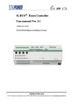
8 “Sensors alarm” function
This function allows you to enable the general channel x to manage the alarms triggered by the Chorus RF
family sensors.
The diagram (Diag. 8.1) below shows the parameters that define the behaviour of the individual channels
(the parameters relative to the Block enabling and Battery alarm object enabling functions were already
illustrated in the General Section).
Diag. 8.1
8.1 Parameters
¾ 8.1.1 Alarm behaviour
This allows you to set the logic value for the telegrams that identify an alarm status; the settings are:
•
direct
This assigns a “1” logic value for an “alarm activated” status and a “0” logic value for an “alarm
deactivated” status.
•
reverse
This assigns a “0” logic value for an “alarm activated” status and a “1” logic value for an “alarm
deactivated” status.
¾ 8.1.2 Cyclic sending time [min]
Here you can set the cyclic sending time for alarm status telegrams, expressed in minutes; the values
range from 1 (minute) to 1000 (minutes).
16