1
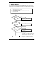
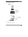
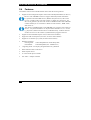
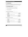
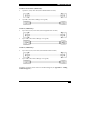
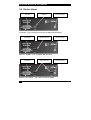
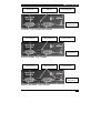
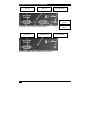
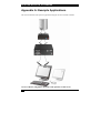
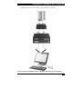
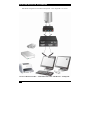
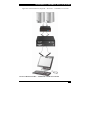
ACS110, ACS120
ACS112, ACS122
ACS201A, ACS202
ACS111, ACS211A
DVI-D-CatX-KVM-Extender
Single and DualHead
Single and Duallink
Manual
http://www.blackbox.com
1
ACS110A-ACS211A -EXTENDER
Welcome to the ACS110A-ACS211A (ACS1xxA)Extender Family!
Thank you for purchasing a ACS1xxA KVM-Extender! We appreciate your business, and we
think you’ll appreciate the many ways that our ACS1xxA KVM-Extender will save you
money, time, and effort.
That’s because our ACS1xxA KVM-Extender is all about breaking away from the traditional
model of attaching a new display to DVI graphic source. Using the ACS1xxA KVMExtender, you can remotely locate monitor, keyboard and mouse up to 10.000m away from
your CPU.
Wherever long distances are usual, e.g. airports, industrial plants, call- centres or in
distributed computer centres, the ACS1xxA KVM-Extender is the best way to solve all
problems in remotely locating your console.
Available in eight different versions, the ACS1xxA KVM-Extender will fit all your
requirements. Four versions support transmission of one or two DVI Singlelink (up to
1920x1200) signals plus USB HID (Keyboard/Mouse) or USB 2.0 (transparent). Two
versions support transmission of one DVI Duallink (up to 2560x2048) signal plus USB HID
(Keyboard/Mouse) or USB 2.0 (transparent). Finally, two versions supporting DVI Singlelink
or DVI Duallink, with USB HID) are available with a 2:1 KVM Switch in the Local Unit.
The devices are adapted for Multimode data transfer.
This manual will tell you all about your new ACS1xxA KVM-Extender, including how to
install, operate, and troubleshoot it. For an introduction to the Converter, see Chapter 2. The
Converter product codes covered in this manual are:
For Multimode-Fibre 50/125µ or 62,5/125µ:
ACS110A:
ACS120A:
ACS112A:
ACS122A:
ACS1xxA KVM- Extender for 1x DVI Singlelink, USB HID (Keyboard/Mouse)
ACS1xxA KVM- Extender for 2x DVI Singlelink, USB HID (Keyboard/Mouse)
ACS1xxA KVM- Extender for 1x DVI Singlelink, USB 2.0 (transparent)
ACS1xxA KVM- Extender for 2x DVI Singlelink, USB 2.0 (transparent)
ACS201A:
ACS202A:
ACS1xxA KVM- Extender for 1x DVI Duallink, USB HID (Keyboard/Mouse)
ACS1xxA KVM- Extender for 1x DVI Duallink, USB 2.0 (transparent)
ACS111A:
ACS1xxA KVM- Extender for 1x DVI Singlelink, USB HID (Keyboard/Mouse)
with KVM- Switch in Local Unit
ACS1xxA KVM- Extender for 1x DVI Duallink, USB HID (Keyboard/Mouse) with
KVM- Switch in Local Unit
ACS211A:
2
ACS110A-ACS211A -EXTENDER
Copyrights and Trademarks
©2008. All rights reserved. This information may not be reproduced in any manner without
the prior written consent of the manufacturer.
Information in this document is subject to change without notice and the manufacturer shall
not be liable for any direct, indirect, special, incidental or consequential damages in
connection with the use of this material.
All trademark and trade names mentioned in this document are acknowledged to be the
property of their respective owners.
Disclaimer
While every precaution has been taken in the preparation of this manual, the manufacturer
assumes no responsibility for errors or omissions. Neither does the manufacturer assume any
liability for damages resulting from the use of the information contained herein. The
manufacturer reserves the right to change the specifications, functions, or circuitry of the
product without notice.
The manufacturer cannot accept liability for damage due to misuse of the product or due to
any other circumstances outside the manufacturer’s control (whether environmental or
installation related). The manufacturer shall not be responsible for any loss, damage, or injury
arising directly, indirectly, or consequently from the use of this product.
Cautions and Notes
The following symbols are used in this guide:
CAUTION: This indicates an important operating instruction
that should be followed to avoid any potential damage to
hardware or property, loss of data, or personal injury.
NOTE. This indicates important information to help you make the best use of
this product.
2
LASER SAFETY PRECAUTIONS
Eye Safety (Laser) with ACS1XXA – Products
Related Norm:
DIN EN 60825-2 ; 11/2007; Safety of optical fibre communication systems (OFCS)
The optical transceivers inside the device have a typical output performance of approx. 5mW.
As per EN 60825-2, this corresponds to Hazard Class 1M.
Accordingly, this device can be operated at unrestricted locations and requires no laser
warning labelling.
The laser ports inside the device will be switched off upon detection of the removal of the
fibre plugs from the sockets (ALV)!
The devices may only be operated with the following warning instruction:
Please observe the following instructions:
Caution
Laser Radiation Hazard Class 1M
Do not view directly
with optical instruments
.
3
ACS110A-ACS211A -EXTENDER
EUROPEAN UNION DECLARATION OF CONFORMITY
This is to certify that, when installed and used according to the instructions in this
manual, together with the specified cables and the maximum cable length <3m, the
Units:
ACS110A, ACS120A, ACS112A, ACS122A
ACS201A, ACS202A, ACS111A, ACS211A
are shielded against the generation of radio interferences in accordance with the
application of Council Directive 89/336/EEC as well as these standards:
EN 55022:
EN 55024:
IEC 61000-4-2:
IEC 61000-4-3:
IEC 61000-4-4:
EN 61000-3-2
EN 61000-3-3
1999
1999
2001
2001
2001
2001
2002
Class A
The device was tested in a typical configuration with PC.
This equipment has been found to comply with the limits for a Class A digital device,
pursuant to Part 15 of the FCC Rules. These limits are designed to provide reasonable
protection against harmful interference when the equipment is operated in a commercial
environment. This equipment generates, uses, and can radiate radio frequency energy and, if
not installed and used in accordance with the instruction manual, may cause harmful
interference to radio communications. Operation of this equipment in a residential area is
likely to cause harmful interference in which case the user will be required to correct the
interference at his own expense.
4
SAFETY-PRECAUTIONS AND
INSTALLATION GUIDLINES
Safety Precautions and Installation Guidelines
To ensure reliable and safe long-term operation, please note the following installation
guidelines:
•
Only use in dry, indoor environments.
•
The Remote unit, Local unit and any power supplies can get warm. Do not locate them
in an enclosed space without any airflow.
•
Do not place power supplies directly on top of a unit.
•
Do not obstruct a unit’s ventilation existing holes.
To safeguard against personal injury and avoid possible
damage to equipment or property, please observe the
following:
•
Only use power supplies originally supplied with the
product or manufacturer-approved replacements. Do not
attempt to dismantle or repair any power supply. Do not
use a power supply if it appears to be defective or has a
damaged case.
•
Connect all power supplies to grounded outlets. In each
case, ensure that the ground connection is maintained
from the outlet socket through to the power supply’s AC
power input.
•
Do not attempt to modify or repair this product.
5
ACS110A-ACS211A -EXTENDER
Contents
1. Quick Setup
7
2. Overview
8
2.1
2.2
2.3
2.4
2.5
2.6
2.7
Introduction
Glossary
Example of a System
Features
Product Range
Compatibility
How to Use This Guide
3. Installation
3.1
3.2
3.3
3.4
3.5
Package Contents
Interconnection Cable Requirements
System Setup
Device Views
Diagnostic LEDs
4. Service Setup
4.1
DIP Switch
8
8
9
10
11
12
13
14
14
16
17
18
22
24
24
5. Troubleshooting
25
Appendix A: Example Applications
26
Appendix B: Rack Mount Options
30
Appendix C: Calling Technical Support
32
Appendix D: List of supported USB devices (for USB HID
versions only)
33
Appendix E: Specifications
34
Appendix F: Connectors
36
6
QUICK SETUP
1. Quick Setup
This section briefly describes how to install your KVM extender system. Unless you are an
experienced user, we recommend that you follow the full procedures described in the rest of
this manual.
Install system
1.
2.
3.
4.
Connect Local unit to CPU or switch.
Connect Remote unit to KVM.
Connect Local unit and Remote unit with Multimode fibre cables.
Power up the system.
NO
Power LED
illuminated?
YES
Link LED*
illuminated?
Check p.s.u.’s and connection
to power outlet
NO
Check the fibre cable, and
fibre connectors
YES
Video OK
LED**
illuminated?
NO
Check settings of graphic card
or boot CPU
YES
Done
* ‚Link LEDs’ are the LEDs at the fibre sockets
– depending on device: ‚Fibre DVI 1’, ‚Fibre
DVI 2’ and/or‚USB’
** ‚Video LEDs’ are the LEDs at the DVI at the
fibre sockets – depending on device‚DVI1’
and/or ‚DVI 2’
7
ACS110A-ACS211A -EXTENDER
2.
Overview
2.1
Introduction
A fibre KVM Extender is mainly used to extend the maximum distance between a CPU and
his Keyboard / Monitor / Mouse considerably. In addition, they are indispensable for
installations in electromagnetic hazardous environments (EMI). Normal Keyboard-/ Monitor/ Mouse extender cables (and Extender using traditional cables) cannot go so far and EMI
interferences may reduce the maximum distance and/or reliability. Using a ACS1xxA
Extender system, these limitations are past. Remain your CPU in a secure rack cabinet or data
center while accessing from an up to 10.000m remotely located place.
A basic KVM extension system comprises a Local unit (transmitter) and a Remote unit
(receiver). The Local unit connects directly to the computer (or a KVM switch system) using
the supplied cable(s). The user console (keyboard, mouse and monitor) attaches to the
Remote unit. The Remote and Local units communicate video and data information along the
interconnecting cable (Multimode fibre).
2.2
Glossary
The following terms are used in this guide:
Fibre
Singlemode or Multimode fibre cable
Multimode
62,5µ Multimode- or
50µ Multimode-fibre cable
KVM
Keyboard, Video and Mouse.
Console
Keyboard, Mouse and Monitor
Single Head
An extender system that supports one monitor + Keyboard/Mouse
Dual Head
An extender system that supports two monitors + Keyboard/Mouse
DDC
Display Data Channel – Communication Interface between CPU and
monitor to retrieve the monitor configuration and to control the monitor,
introduced by Video Electronics Standards Association (VESA). DDC2B
is supported to retrieve the EDID Information.
DVI
Digital Video standard, installed by Digital Display Working Group
(www.ddwg.org) R, G, B, CLOCK in a data stream with up to
3x 1,6 Gbit/sec. Signals are TMDS Level.
PSU
The desktop power supply connected to the Local/Remote unit.
HID
Human Interface Devices are units, which are used for human access to
the CPU. They are a USB-device class of its own (e.g. Memory Devices
etc.). Besides of keyboard and mouse also touch screen, light pen,
fingerprint sensor, graphic tablets etc. are HID devices.
8
OVERVIEW
2.3
Example of a System
CPU with DVI-D
Graphic card
Local Unit
ACS1xxA KVMExtendersystem
Remote Unit
Optional
2nd Monitor
Remote Console
ACS1xxA – KVM Extender system (example)
9
ACS110A-ACS211A -EXTENDER
2.4
Features
All members of the ACS1xxA KVM Extender Series offer the following features:
•
Support for DVI-D Singlelink Graphic cards and for USB-Keyboard/Mouse (all devices)
Devices with USB-HID connectors support ONLY Keyboard and Mouse.
It’s possible that other HID devices (Human Interface Device) like touchscreens, graphics tablets, barcode readers or similar are supported – but
there is no guarantee for this! The ACS1xxA KVM-Extender with USB HID
is NOT suitable for use with other USB devices like Scanner, WEB- Cams,
data sticks etc.
The ACS1xxA KVM-Extender with USB HID never supports more than two
devices – Keyboard and Mouse or Keyboard and Touchscreen, etc. but not
e.g. Keyboard, Mouse and Touchscreen simultaneously. A Hub is allowed
but does not increase the number of simultaneously supported devices
•
Support for DVI-D Duallink Graphic cards (ACS201A and ACS202A)
•
Support for USB-2.0 transparent (ACS112A, ACS122A and ACS202A)
•
Support for two monitors per system (ACS120A and ACS122A)
•
Maximum resolution:
DVI Singlelink:
DVI Duallink:
•
1920x1200@60Hz bzw.1280x1024@75Hz;
2560x2048@60Hz (max. 330MPixel/sec)
Supporting 24 Bit- color depth @ Singlelink and more @ Duallink.
•
Status indicator LEDs on each device.
•
Small footprint chassis.
•
19’’ Rack mount options available.
•
CPU cables + Adapters included.
10
OVERVIEW
2.5
Product Range
There are 8 products in the range and various upgrade kits:
ACS1xxA – Extender (fibre)
ACS110A
ACS120A
ACS112A
ACS122A
ACS201A
ACS202A
ACS111A
ACS211A
ACS1xxA KVM- Extender for 1x DVI Singlelink, USB
HID (Keyboard/Mouse)
ACS1xxA KVM- Extender for 2x DVI Singlelink, USB
HID (Keyboard/Mouse)
ACS1xxA KVM- Extender for 1x DVI Singlelink, USB
2.0 (transparent)
ACS1xxA KVM- Extender for 2x DVI Singlelink, USB
2.0 (transparent)
ACS1xxA KVM- Extender for 1x DVI Duallink, USB
HID (Keyboard/Mouse)
ACS1xxA KVM- Extender for 1x DVI Duallink, USB
2.0 (transparent)
ACS1xxA KVM- Extender for 1x DVI Singlelink, USB
HID (Keyboard/Mouse) with KVM- Switch in Local Unit
ACS1xxA KVM- Extender for 1x DVI Duallink, USB
HID (Keyboard/Mouse) with KVM- Switch in Local Unit
Upgrade Kits
RMK253A
19”/1HE Rackmount- Kit to mount up to 3 Singlehead
devices
11
ACS110A-ACS211A -EXTENDER
2.6
Compatibility
Interface Compatibility
•
Digital Video (DVI-D) Singlelink: Digital Video standard, installed by
Digital Display Working Group (www.ddwg.org) R, G, B, CLOCK in a data
stream with up to
3x1,6 Gbit/sec. Signals are TMDS Level. Maximum Resolution is 1920x1200.
•
Digital Video (DVI-D) Duallink: Digital Video standard, installed by Digital
Display Working Group (www.ddwg.org) RR, GG, BB, CLOCK in a data
stream with up to
6x1,6 Gbit/sec. Signals are TMDS Level. Maximum Resolution is 2560x2048.
•
USB Keyboard: Compatible with all standard keyboards. Certain keyboards
with enhanced features may also be supported with custom firmware.
Keyboards with built-in hub are also supported – but there are never more than
two HDI devices supported.
•
USB Mouse: Compatible with all standard 2-button, 3-button and wheel mice.
Devices with USB- connectors support ONLY Keyboard and Mouse. It’s
possible, that other HID devices (Human Interface Device) like touchscreens, graphics tablets, barcode readers or similar are supported – but
there is no guarantee for this! The DVI-D Cat X KVM-Extender is NOT
suitable for use with other USB devices like Scanner, WEB- Cams, data
sticks etc.
The device never supports more than two devices – Keyboard and Mouse
or Keyboard and Touchscreen, etc. but not e.g. Keyboard, Mouse and
Touchscreen simultaneously. A Hub is allowed but does not raise the
number of supported devices
•
12
USB 2.0 transparent (ACS112A, ACS122A and ACS202A only):
Compatible with all USB 2.0 compliant devices.
OVERVIEW
2.7 How to Use This Guide
This guide describes the installation and configuration of the ACS1xxA – Extender. Although
the connection and operation of the system is relatively straightforward, you should consider
the following before getting started:
Connection & Compatibility
If you have purchased an Extender Kit, this will contain all the cables required to connect the
Local unit of your ACS1xxA KVM- Extender to your PC or KVM switch. Please see also:
Package Contents (page 14)
For information about connection and installation, see Installation, page 14.
DDC Information
Normally, it is not necessary to make any adjustments to the ACS1xxA - Extender. DDC
Information is continuously transmitted from the remote monitor to the CPU graphic card.
Compatibility
Devices with USB HID connectors are NOT compatible to devices with USB-2.0 connectors.
Devices with DVI Singlelink and DVI Duallink are compatible if the second fibre is not used.
Only one DVI Singlelink signal will be transmitted in this case.
13
ACS110A-ACS211A -EXTENDER
3. Installation
For first-time users, we recommend that you carry out a test placement, confined to a single
room, before commencing full installation. This will allow you to identify and solve any
cabling problems, and experiment with the KVM extender system more conveniently.
3.1 Package Contents
You should receive the following items in your extender package:
•
ACS1xxA KVM-Extender- pair (Local Unit + Remote Unit)
•
2x 5V DC universal power supply for the ACS1xxA - Extender
•
2x German type power cord
•
User manual (Quick Setup)
ACS110A and ACS112A (additionally):
•
1 pc. DVI-I (1,8m) video cable (DVI-I Singlelink male-to-male)
•
1 pc.USB (1,8m) cable (USB type A to type B)
ACS120A and ACS122A (additionally):
•
2 pcs. DVI-I (1,8m) video cable (DVI-I Singlelink male-to-male)
•
1 pc.USB (1,8m) cable (USB type A to type B)
14
INSTALLATION
ACS201A and ACS202A (additionally):
•
1 pc.DVI-I (1,8m) video cable (DVI-I Duallink male-to-male)
•
1 pc.USB (1,8m) cable (USB type A to type B)
ACS111A (additionally):
•
2 pcs. DVI-I (1,8m) video cable (DVI-I Singlelink male-to-male)
•
2 pcs. USB (1,8m) cable (USB type A to type B)
ACS211A (additionally):
•
2 pcs. DVI-I (1,8m) video cable (DVI-I Duallink male-to-male)
•
2 pcs. USB (1,8m) cable (USB type A to type B)
If anything is missing, please contact our Technical Support (see Appendix F – Calling
Technical Support).
15
ACS110A-ACS211A -EXTENDER
3.2 Interconnection Cable Requirements
To connect the Local and Remote units you will need:
•
DVI: Connect the supplied DVI cable(s) to your CPU(s) (KVM - Switch, etc.). Please
ensure that the connection is tension-free!
•
USB-Keyboard, USB-Mouse, USB 2.0: Connect the supplied USB cable(s) to your
CPU (USB-A to USB-B). Please ensure that the connection is tension-free!
•
Fibre Cables:
•
Multimode: Two fibres 50μm or 62.5μm. E.g. I-V(ZN)H 2G50 (In house
patch cable)or I-V(ZN)HH 2G62,5 (In house Breakout cable) or I/AD(ZN)H
4G50 (In house OR Outdoor Breakout cable, stress resistant) or
A/DQ(ZN)B2Y 4G62,5 (Outdoor cable, stress resistant with protection against
animal biting). All notations acc. to VDE specification.
1 fibre:
2 fibre:
3 fibre:
ACS110A and ACS111A
ACS120A, ACS112A, ACS201A and ACS211A
ACS122A and ACS202A
A point to point connection is required. Having one or more patch panels
in the line is possible and allowed. Not allowed is a connection from the
fibre link interface to any other products, especially telecommunications or
network equipment.
•
16
Power Supply: Connect the supplied 5V/DC power supplies to the Plug terminal on the
rear of both the local and the remote unit.
INSTALLATION
3.3 System Setup
To install your ACS1xxA – Extender system:
1.
Switch off all devices.
2.
Connect your keyboard, monitor(s) and mouse to the Remote unit (depending on device
type).
3.
Using the supplied CPU KVM cable(s), connect the local unit to your computer (or
KVM switch).
4.
Connect the interconnect cable (fibre cable) to the local and the remote unit.
5.
Connect the 5V power supply to power the unit.
Only use the power supply originally supplied with this
equipment or a manufacturer-approved replacement.
6.
Power up the system.
17
ACS110A-ACS211A -EXTENDER
3.4 Device Views
Connect to CPU
DVI Port
Connect to CPU
USB Port
Connect to
5V Power Supply
Local Unit – Type ACS110A, ACS112A, ACS201A and ACS202A
Connect to Remote
DVI Monitor
Connect to Remote
USB-Keyboard/ Mouse
Connect to
5V Power Supply
Remote Unit HID – Type ACS110A and ACS201A
Connect to Remote
DVI Monitor
Connect to Remote
USB 2.0 Devices
Remote Unit USB 2.0 – Type ACS112A and ACS202A
18
Connect to
5V Power Supply
INSTALLATION
Connect to CPU
DVI Port #1
Connect to CPU
USB Port
Connect to
5V Power Supply
Connect to CPU
DVI Port #2
Local Unit – Type ACS120A and ACS122A
Connect to Remote
DVI Monitor #1
Connect to Remote
USB-Keyboard/ Mouse
Connect to
5V Power Supply
Connect to Remote
DVI Monitor #2
Remote Unit HID – Type ACS120A
Connect to Remote
DVI Monitor #1
Connect to Remote
USB 2.0 Devices
Connect to
5V Power Supply
Connect to Remote
DVI Monitor #2
Remote Unit USB 2.0 – Type ACS122A
19
ACS110A-ACS211A -EXTENDER
Connect to CPU #1
DVI Port
Connect to CPU #1
USB Port
Connect to
5V Power Supply
Connect to CPU #2
DVI Port
Local Unit – Type ACS111A and ACS211A
Connect to Remote
DVI Monitor
Connect to Remote
USB-Keyboard/ Mouse
Remote Unit HID – Type ACS111A and ACS211A
20
Connect to CPU #1
DVI Port
Connect to
5V Power Supply
INSTALLATION
Multimode Fibre Connectors – Type ACS110A and ACS111A
Multimode Fibre Connectors – Type ACS120A, ACS201A and ACS211A
Multimode Fibre Connectors – Type ACS112A
Multimode Fibre Connectors – Type ACS122A and ACS202A
21
ACS110A-ACS211A -EXTENDER
3.5
Diagnostic LEDs
Each ACS1xxA KVM-Extender is fitted with up to six indicator LEDs: Power, Video OK,
and Link Status. The location of the LEDs is shown below:
Diagnostic LED
DVI 1
Diagnostic LED
DVI 2
Diagnostic LED
Power
Diagnostic LEDs at the ACS1xxA – Extender (DVI Sockets)
LED
Appearance
Diagnostics
Power LED
(Red LED)
Off
On
Device not ready
Device ready
DVI 1
(Red LED)
Blinking
Monitor DDC is being transmitted from Remote
Unit to Local Unit and stored there (only if video
source switched off or not connected)
DVI signal from video source available
DVI signal from video source NOT available
Off
On
DVI 2
(Red LED)
Blinking
Off
On
22
Monitor DDC is being transmitted from Remote
Unit to Local Unit and stored there (only if video
source switched off or not connected)
DVI signal from video source available
DVI signal from video source NOT available
INSTALLATION
Diagnostic LED
USB
Diagnostic LED
Fibre DVI 1
Diagnostic LED
Fibre DVI 2
Diagnostic LEDs at the ACS1xxA – Extender (Fibre Sockets)
LED
Appearance
Diagnostics
Fibre DVI 1
(Green LED)
Off
On
No Connection to DVI 1 Port at Local/Remote Unit
Connection to DVI 1 Port at Local/Remote Unit
OK
Fibre DVI 2
(Green LED)
Off
On
No Connection to DVI 2 Port at Local/Remote Unit
Connection to DVI 2 Port at Local/Remote Unit
OK
USB
(Green LED)
Off
On
No Connection to USB Port at Local/Remote Unit
Connection to USB Port at Local/Remote Unit OK
23
ACS110A-ACS211A -EXTENDER
4.
Service Setup
There are no adjustments required to set up your ACS1xxA KVM -Extender. You might be
requested by our service technicians to setup a special configuration. In this case you will
receive detailed instructions.
4.1
DIP Switch
Local Unit and Remote Unit contain a DIP Switch with 4 switch options.
All 4 switches of the DIP Switch must be ‚OFF’ during operation. Other
switch configurations can lead to malfunction during operation!
During service you will receive detailed instructions by our service technicians, how and in
which order you should set the switches.
Location and standard position of the DIP Switch are shown below:
24
TROUBLESHOOTING
5.
Troubleshooting
Monitor
There is no picture.
Check the power supply connection at the Local and Remote unit. Is the Power
(Red LED) at the Local and Remote unit illuminated? If not, the internal powersupply may be damaged or there may be an internal error.
Check that the Interconnection cable is connected at the Local Unit and the Remote
Unit. Is the Link Status LED illuminated? If not, there may be a problem with the
Interconnection cable:
Are there Errors through data transmission over fibre Cable? Is the Data Error LED
illuminated or blinking?
‚DVI 1’ and/or ‚DVI 2’ LED are off: CPU does not provide a video signal – Check
settings of the graphic card.
USB-Keyboard/USB-Mouse
Your USB-keyboard/USB-mouse does not work
Although we tried to design the devices as transparent as possible, we can’t ensure
that all devices are running. Please check on page 33 the list of the tested devices.
USB-HID Device
Your USB-HID device does not work
Although our interface supports HID devices, we can’t ensure that every connected
device is running. In case of a malfunction please contact our technical support.
Other USB-devices
Your USB- device does not work (ACS1xxA without USB 2.0 only)
You have connected a non-HID device. Only HID devices are supported. All other
devices are ignored.
25
ACS110A-ACS211A -EXTENDER
Appendix A: Example Applications
This section illustrates some specific applications using the ACS1xxA KVM- Extender:
ACS1xxA KVM- (Singlelink-) Extender with optional, second screen.
26
APPENDIX A: EXAMPLE APPLICATIONS
For highest resolution up to 2560x2048 – DVI- Duallink over 2 fibres
ACS1xxA KVM- Duallink Extender – Highest Resolution up to 2560x2048
27
ACS110A-ACS211A -EXTENDER
Dual-Head Configuration with USB 2.0 transparent – DVI- Singlelink over 3 fibres
ACS1xxA KVM- Extender – with USB 2.0 for ALL USB Devices – FullSpeed!
28
APPENDIX A: EXAMPLE APPLICATIONS
Application with KVM-Switch (Singlelink – shown here – or Duallink) in Local Unit
ACS1xxA KVM- Extender – with KVM- Switch in Local Unit
29
ACS110A-ACS211A -EXTENDER
Appendix B: Rack Mount Options
ACS1XXA KVM-Extenders can be mounted into a 19“-Server Rack using the DDXIRackmount Kit.
The DDXi Rackmount Kit consists of the following parts:
Narrow strip
Two small blanking plates
Wide blanking plate
Base plate
M3x5 Screws (14)
Mounting instruction:
1.
Align the holes on the base plate with the vacant screw holes on the base of the device.
2.
Fasten the base of the unit –using only the supplied, short screws – to the plate of the
mounting kit.
Only use the supplied, short screws, to prevent damages on
the PCB’s
3.
30
Close the remaining gaps with blanking plates.
APPENDIX B: RACK MOUNT OPTIONS
The 19“ DDXI- Rackmount kit allows you to mount various numbers of devices into one
housing:
1. One unit (using two small plates)
2. Two units (using one small plate)
3. Three units
31
ACS110A-ACS211A -EXTENDER
Appendix C: Calling Technical Support
If you determine that your DDXI - DVI KVM Extender is malfunctioning, do not attempt to
alter or to repair it. It contains no user-serviceable parts. Please contact our Technical
Support.
Please make a record of the history of the problem upfront. We will be able to provide more
efficient and accurate assistance if you can provide a complete description, including:
•
The firmware-revision level printed on the bottom of the Extender (very
important):
Version Number Format:
Board:
xxLO/RE Myyy Pzzz Auuu Gvvvvvv
Transceiver:
C/M/S xx Pyy Mzz
Keyboard/Mouse:
P/U xx Vyyy
•
The nature and duration of the problem.
•
When the problem occurs.
•
The components involved in the problem—that is, what type of computers,
what type of keyboard, brand of mouse, make and model of monitor, type and
make of cable, etc.
•
Any particular application that, when used, appears to create the problem or
make it worse.
•
The results of any testing you’ve already done.
To solve some problems, it might be necessary to upgrade the ACS1xxA KVM- Extender
firmware. If this turns out to be the case for your difficulty, our Technical Support technicians
will arrange for you to receive the new firmware and will tell you how to install it.
Shipping and Packaging
If you need to transport or ship your ACS1xxA KVM Extender:
•
Package it carefully. We recommend that you use the original container.
•
If you are shipping it for repair, please include the Unit’s external power supplies. If you
are returning it, please include everything you received with it. Before you ship the
Extender back to your dealer for repair or return, contact him to receive a Return
Authorization (RA) number.
32
APPENDIX D: LIST OF SUPPORTED USB DEVICES (FOR
USB HID VERSIONS ONLY)
Appendix D: List of supported USB devices
(for USB HID versions only)
Although the USB connection’s implementation allows all keyboards and Mice, we can not
guarantee that all available keyboards/mice are running.
The implementation is constructed for “HID” devices. HID is a device class enabling inputs
in a PC. Among others, touch screen, graphic tablet, fingerprint sensors are HID devices.
Some devices install additional devices, e.g. to set parameters. Such devices are NOT
supported by our extenders. Please remark additionally that installing more than two devices
is not possible even if you use a USB hub.
The following devices are tested and have been found correct:
Keyboards
•
Mice
•
33
ACS110A-ACS211A -EXTENDER
Appendix E: Specifications
Power Supply
Voltage
90-240VAC-0.5A-47-63Hz/5VDC-2000 mA
Power required
Local Unit : max. 750mA
Remote Unit : max. 750mA
Interface
(Depending on type of device)
Video source/Monitor
Singlelink devices
Duallink devices
DVI-D up to 1920x1200@60Hz
DVI-D up to 2560x2048@60Hz
Keyboard
USB
Mouse
USB 2-/3-button and wheel mouse
USB
USB 2.0 (optional)
Maximum Length of Interconnection Cable
Multimode 50μm
400m (1.300ft)
Multimode 62.5μm
200m (650ft)
34
APPENDIX E: SPECIFICATIONS
Type of Interconnection Cable
Multimode 50μm
Two fibres 50μm, E.g. I-V(ZN)H 2G50 (In house
patch cable) or I/AD(ZN)H 4G50 (in house OR
outdoor Breakout cable, stress resistant) All notations
acc. VDE specification.
Multimode 62.5μm
Two fibres 62.5μm. E.g. I-V(ZN)HH 2G62,5 (In
house Breakout cable) or A/DQ(ZN)B2Y 4G62,5
(outdoor cable, stress resistant with protection against
animal biting) All notations acc. VDE specification.
Plug type
For all cables: SC
Size and Shipping Weight
ACS1xxA Singlehead
133 x 180 x 43mm (5.2”x7.1”x1.7”)
Weight Local/Remote Unit: 1,2kg (2.6lb)
Shipping box
460x250x65mm (18.1”x9.8”x2.6”)
Weight: 4,3kg (9.5lb)
Environmental Conditions
Operating Temperature
41 to 113°F (5 to 45 °C)
Storage Temperature
-13 to 140°F (-25 to 60 °C)
Relative Humidity
max. 80% non-condensing
35
ACS110A-ACS211A -EXTENDER
Appendix F: Connectors
ACS1xxA KVM-Extender Connector Pinouts
DVI-I Socket (Singlelink)
1
8 C1 C2
C5
17
Pin
Signal
24
Pin
Signal
C3 C4
Pin
Signal
1
T.M.D.S data 2-
9
T.M.D.S data 1-
17
T.M.D.S data 0-
2
T.M.D.S data 2+
10
T.M.D.S data 1+
18
T.M.D.S data 0+
3
T.M.D.S data 2 GND
11
T.M.D.S data 1 GND
19
T.M.D.S data 0 GND
4
n.c.
12
n.c.
20
n.c.
5
n.c.
13
n.c.
21
n.c.
6
DDC Input (SCL)
14
+5V high impedance
22
T.M.D.S clock GND
7
DDC Output(SDA)
15
GND
23
T.M.D.S clock +
8
Internal use
16
Hot Plug recognition
24
T.M.D.S clock -
C1
Internal use
C3
Internal use
C2
n.c.
C4
Internal use
36
C5
GND
APPENDIX F: CONNECTORS
DVI-I Socket (Duallink)
1
8 C1 C2
C5
17
Pin
Signal
24 C3 C4
Pin
Signal
Pin
Signal
1
T.M.D.S data 2-
9
T.M.D.S data 1-
17
T.M.D.S data 0-
2
T.M.D.S data 2+
10
T.M.D.S data 1+
18
T.M.D.S data 0+
3
T.M.D.S data 2,4 GND
11
T.M.D.S data 1,3 GND
19
T.M.D.S data 0,5 GND
4
T.M.D.S data 4-
12
T.M.D.S data 3-
20
T.M.D.S data 5-
5
T.M.D.S data 4+
13
T.M.D.S data 3+
21
T.M.D.S data 5+
6
DDC Input (SCL)
14
+5V high impedance
22
T.M.D.S clock GND
7
DDC Output(SDA)
15
GND
23
T.M.D.S clock +
8
Internal use
16
Hot Plug recognition
24
T.M.D.S clock -
C1
Internal use
C3
Internal use
C2
n.c.
C5
GND
C4
Internal use
37
ACS110A-ACS211A -EXTENDER
Keyboard/Mouse Socket, USB Type B
(Socket at Local Unit)
Pin
Signal
1
VCC (+5V)
Red
2
Data -
White
3
Data +
Green
4
GND
Black
Keyboard/Mouse Socket, USB Type A
(Socket at Remote Unit)
38
Pin
Signal
1
VCC (+5V)
Red
2
Data -
White
3
Data +
Green
4
GND
Black
APPENDIX F: CONNECTORS
Power – 2.5mm barrel type
Pin
Signal
inner
+5V
outer
GND
39
NOTES