1
Evolution Series
Digital indicator system
E1205 and E1210
Operating Instructions
ENGLISH
This manual for Build 5
standard and beyond
76103-950 Issue AG May 2010
© Avery Weigh-Tronix, LLC 2010 All rights reserved.
No part of this publication may be reproduced, stored in an electronic retrieval system, or
transmitted in any form or by any means, electronic, mechanical, photocopying, recording
or otherwise without the prior written consent of the copyright owner, or as permitted by law
or under license. Full acknowledgment of the source must be given. Avery Weigh-Tronix is
a registered trade mark of the Avery Weigh-Tronix, LLC. This publication was correct at the
time of going to print however, Avery Weigh-Tronix, LLC reserves the right to alter without
notice the specification, design, price or conditions of supply of any product or service at any
time.
All third party brands and product names used within this document are trademarks or
registered trademarks of their respective holders.
IMPORTANT
When programming or configuring the equipment you must ensure that you comply with all
relevant standards and legislation. The example settings given in this book may not be legal
for trade with the public.
E12xx_u_en_76103_950.book
Contents
page
1
Warnings
8
Installation and Service
8
1.1
Environmental Parameters
8
1.2
Safe installation
8
1.3
Safe use
9
1.3.1
Routine maintenance
9
1.3.2
Cleaning the machine
9
1.3.3
Training
9
2
1.3.4
Sharp objects
1.3.5
EMC compliance
9
10
Getting started
12
2.1
Description
12
2.2
Displays and keys
13
2.3
Displays
14
2.4
Keyboard
16
3
Basic weighing
20
3.1
Introduction
20
3.2
Weighing goods
22
3.3
Tare / Net weighing
23
3.3.1
Push-button tare
23
3.3.2
To recall a stored tare
24
3.3.3
Keyboard tare
25
3.3.4
Gross / Tare / Net display
26
3.4
Totals
27
3.5
Weighing errors
29
E1205/E1210 Operating Instructions
3
3.6
PLUs
3.6.1
Recalling a PLU
30
3.6.2
PLU totals
32
3.6.3
Stored tares
33
3.6.4
Cancelling an active PLU
34
4
Advanced Functions
35
4.1
Selecting the options
35
4.2
STATUS - Indicator status / test
37
4.3
CHECK - Checkweighing
39
4.3.1
Setting the checkweigh target
40
4.3.2
STEP - Checkweigh bars
42
4.3.3
Using checkweigh
42
4.4
CONV - Conversion mode
44
4.5
LIST - Product listing
47
4.6
PACK - Pack runs
51
4.6.1
Setting up the pack run
52
4.6.2
Using the pack run
55
4.7
PEAK_H - Peak hold
58
4.8
RECIPE - Run or edit a recipe sequence
59
4.8.1
61
4.9
Recipe Batching
ALARM - Edit alarms
62
4.10 TYPE - Type through mode
63
4.11 MOTION - In motion weighing
64
4.12 CYLF - Cylinder filling
66
4.13 OFFLINE - Stored print transactions
73
5
COUNT - Counting application
75
5.1
Introduction
75
5.2
Setting the piece weight
76
5.2.1
5.3
4
30
Fast sampling
Dribble sampling
77
79
E1205/E1210 Operating Instructions
5.3.1
5.4
Dribble sample procedure
79
Bulk sampling
82
5.4.1
82
Bulk sample procedure
5.5
Entering the piece weight
85
5.6
Entering a count target
86
5.7
Counting
87
5.8
Counting using PLUs
89
6
TRUCK - Weighbridge
91
6.1
Introduction
91
6.2
Single stage weighing
95
6.3
Two-stage weighing
97
6.4
Multi-stage weighing
100
6.5
NWA - Net weight adjust
101
6.6
RET WT - Vehicle records
103
6.7
AXLE WT - Axle weighing
106
6.8
Vehicle PLUs
110
6.9
BROWSE - Stored information
111
6.10 Weighbridge errors
7
SUPER - Supervisor Mode
7.1
Entering supervisor mode
113
115
115
7.2
EXIT - Exiting supervisor mode
117
7.3
PRINT - Print configuration settings
118
7.4
REPORTS - Weighbridge reports
119
7.5
ALTER - Configuring the indicator
121
7.6
TARES - Stored tares
123
7.6.1
123
EDIT - Create / edit stored tares
7.7
PASSWD - Changing passwords
126
7.8
CONV - Conversion units
127
CLOCK - Date and time
129
7.9.1
129
7.9
DATE - Set date and format
E1205/E1210 Operating Instructions
5
7.9.2
TIME - Set time and format
131
7.9.3
Date and Time separators
132
7.10 ACCESS - Password protection
7.11 LCD - Display contrast
135
7.12 FIELDS - User fields
136
7.13 CHECK - Checkweigh text
138
7.14 CALIB - Calibration report
140
7.15 TRANS - Transaction log
141
7.16 RECRDS - Vehicle records
144
7.17 AUDIT - Audit log
146
7.18 BATCH Information
147
7.19 INFO - Information line
148
7.20 KEYBRD - Enable / Disable keys
149
7.21 NETWRK - Network details
150
7.22 S_KEY - Remote keyboard emulation
152
7.23 REC. NO - Batch receipt number
154
7.24 COUNTR - Resettable counter
154
7.25 PWR UP - Power up mode
154
7.26 CYLF - Cylinder filling
154
8
SUPER PLU MODE
8.1
Enter SUPER PLU MODE
155
8.1.1
157
Change menu titles
155
8.2
Exit SUPER PLU MODE
159
8.3
Create / Edit PLUs
160
8.4
PLU configuration options
161
9
RECIPE programming
9.1
Recipes (RECIPE)
181
9.2
Create / Edit recipe
183
Recipe configuration options
184
9.3.1
184
9.3
6
133
EDIT - Edit selected recipe
181
E1205/E1210 Operating Instructions
9.4
Input / Output states
10
ALARMS
195
10.1 Introduction
195
10.2 Create / Edit alarm
197
10.3 Alarm configuration options
198
10.3.1 EDIT - Edit selected alarm
10.4 Input / Output states
E1205/E1210 Operating Instructions
193
198
204
7
1 Warnings
1
Warnings
Installation and Service
THE EQUIPMENT CONTAINS NO USER SERVICABLE
COMPONENTS.
Installation and maintenance of the equipment must only be
carried out by trained and authorised personnel.
1.1
1.2
Environmental Parameters
Power
Requirements:
110-240 VAC 50/60Hz 1.85Amps
Climatic
Environment:
-10 to +40°C, closed, noncondensing
EM Classification:
E2
Weight:
3.75kg (E1105, E1205)
5kg (E1110/E1210)
Dimensions:
280mm W x 280mm H x 110mm D
Safe installation
For your protection all mains (110V or 230V) equipment used
out of doors or in wet or damp conditions should be supplied
from a correctly fused source and protected by an approved
30 mA Residual Current Device (RCD) to BS7071 or BS7288
or IEC1008-2-2 BS EN 61008:1995.
The mains lead must be connected to a supply outlet with a
protective earth contact. The electrical supply at the socket
outlet must provide over current protection of an appropriate
rating.
Pluggable equipment must be installed near an easily
accessible socket outlet. Isolate the machine by unplugging
from the socket outlet.
8
E1205/E1210 Operating Instructions
1 Warnings
1.3
Safe use
1.3.1
Routine maintenance
To avoid the possibility of electric shock or damage to the
machine, always switch off the machine and isolate from
the power supply before carrying out any routine
maintenance.
To avoid the risk of the machine falling, where applicable,
ensure that it is placed securely on a flat and level surface.
1.3.2
Cleaning the machine
The outside of standard products may be wiped down with a
clean cloth, moistened with water containing a small amount
of mild detergent.
Harsh abrasives, solvents, scouring cleaners and alkaline
cleaning solutions, such as washing soda, should not be
used especially on the display windows. Under no
circumstances should you attempt to wipe the inside of
the machine.
Do not spray any liquid directly onto the display
windows. If you are using a proprietary cleaning fluid
ensure you spray the cloth and not the display.
1.3.3
Training
Do not attempt to operate or carry out any procedure on a
machine unless you have received the appropriate training or
read the Instruction Books.
To avoid the risk of RSI (Repetitive Strain Injury) it is
important to ensure that the machine is placed on a surface
which is ergonomically satisfactory to the user. It is
recommended that frequent breaks are taken during
prolonged usage.
1.3.4
Sharp objects
Do not use sharp objects (screwdrivers, long fingernails etc.)
to operate the keys.
E1205/E1210 Operating Instructions
9
1 Warnings
1.3.5
EMC compliance
The following warning may be applicable to your machine.
WARNING:This is a class A product. In a domestic
environment this product may cause radio interference in
which case the user may be required to take adequate
measures.
10
E1205/E1210 Operating Instructions
2 Getting started
2
Getting started
2.1
Description
2.1 Description
The E12 Series is a range of digital indicators suitable for
general weighing or more specialist applications such as
check-weighing, counting, weighbridge applications, recipes
and pack runs. The indicator can be connected to a printer,
remote display or PC.
The E12 Series comprises the following products:
O
E1205 indicator which comes in a plastic housing and is
suitable for general use.
O
E1210 indicator which comes in a stainless steel housing
and is suitable for more rigorous environments such as
damp or wet areas.
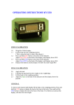
Figure 2.1 E1210 indicator
12
E1205/E1210 Operating Instructions
2.2 Displays and keys
2.2
2 Getting started
Displays and keys
Overlay
Alphanumeric display
Variable (‘soft’)
function keys
Fixed function keys
Keypad keys
Figure 2.2 E1205 / E1210 overlay
E1205/E1210 Operating Instructions
13
2 Getting started
2.3
2.3 Displays
Displays
Figure 2.3 Typical display (zero weight)
Figure 2.4 Dual weight display example
The indicator has an LCD display used to display weight
information, icons and messages.
Information icons
The following icons may be displayed:
Display shows the gross weight.
Display shows the tare weight.
Display shows the net weight.
(Tare is in operation)
The weight is unsteady.
Preset tare in operation.
14
E1205/E1210 Operating Instructions
2.3 Displays
2 Getting started
Weight display in pounds.
Weight display in kilogrammes.
Note: When the displayed weight is not lb or kg but is a
custom unit, the indicator displays the appropriate custom unit
symbol.
Illuminated output is active.
The indicator is set to count mode. The value
displayed is the number of items and not the
weight.
Print indication.
Zero icon.
Scale 1 or scale 2.
Indicates the current scale.
E1205/E1210 Operating Instructions
15
2 Getting started
2.4
2.4 Keyboard
Keyboard
General keys
The E1205 and E1210 indicators have the keys shown below.
Note: Your indicator may have some keys disabled.
Tare key.
Set / cancel a tare weight.
Select key.
Toggle between the available weight
readings (gross, tare, net).
Zero key.
Resets the display to show zero weight.
Print key.
Print weight information to connected printer
(or other connected device).
16
E1205/E1210 Operating Instructions
2.4 Keyboard
2 Getting started
Units select key.
Switch between the available units of
measure (e.g. kg and lb).
Totals key.
Display the sub and grand totals.
Standby/PLU key.
Short press PLU key. Select a PLU.
Long press Standby key. Put the indicator
into standby mode. Press again to set the
indicator back to operator mode.
Scale select key.
Toggle between the connected scales /
platforms.
Escape key.
Quit out of a menu option or cancel a
numeric entry without accepting the value.
Clear/cancel key.
Clear entered values or cancel an operation.
Enter key.
Accept the value shown on the display.
....
Numeric keys for data entry.
Decimal point key.
Also used to enter negative values e.g. -7.0.
Text Key.
Press and hold to use keypad for text entry.
E1205/E1210 Operating Instructions
17
2 Getting started
2.4 Keyboard
Variable function (F) keys
Function currently
assigned to F1 key
Function currently
assigned to F3 key
F5 key displays
more options
>>
Keys with variable (‘soft’) function
Figure 2.5 Function keys
Press a function key to select the option displayed above the
key. The options available depend on the indicator operating
mode and its configuration.
If there is no text or symbol above an ‘F’ key, then it has no
function at that time.
Note: Where you see >> press the appropriate ‘F’ key to
display more options.
18
E1205/E1210 Operating Instructions
3 Basic weighing
3.1 Introduction
3
Basic weighing
3.1
Introduction
Basic weighing (operator) mode is the default mode of the
indicator.
Basic weighing display:
Selected scale
Weight unsteady icon
Weight display
Unit of
measure
Print indicator
(Only displayed when printing)
Applications and advanced weighing options
(see Advanced Functions on page 35)
Unsteady weight
Indicates that the weight is not yet steady. Take your weight
reading once this icon is no longer displayed.
Weight units
Your indicator may have been configured to support multiple
units of weight. Press the UNITS key to select between them.
Custom
kg or lb or unit
20
E1205/E1210 Operating Instructions
3.1 Introduction
3 Basic weighing
Select scale
Your indicator may have more than 1 scale connected. Press
the SCALE key to select between them.
Scale 1
Scale 2
Combined
weighbridge
Note: WEIGHBRIDGE ONLY: For more information on
combined weights see Combined weight / Long vehicles on
page 93.
Print
Your indicator may have a printer connected (or another
device for reporting / storing the weight data).
Press the PRINT key to send the weight to the printer or other
connected device.
Print indicator
E1205/E1210 Operating Instructions
21
3 Basic weighing
3.2
3.2 Weighing goods
Weighing goods
1.
Ensure the scale is empty.
2.
Check that the display reads
zero. (Press the ZERO key if
required.)
3.
Place the goods on the scale.
4.
Take the weight reading and
PRINT if required.
Example displays
0.00
gross
kg
STATUS SUPER
7.50
gross
kg
STATUS SUPER
5.
Remove the goods from the
scale.
0.00
gross
kg
STATUS SUPER
22
E1205/E1210 Operating Instructions
3.3 Tare / Net weighing
3.3
3 Basic weighing
Tare / Net weighing
Tares are used when goods need to be packed into a
container or weighed onto a vehicle. The tare function will
subtract (tare off) the weight of the container (or vehicle) from
the total weight on the scale.
•
Net Weight. This is the weight of the goods in the
container. The net weight is displayed when a tare is
active.
Note: The type of tare available depends on how the machine
was configured on installation.
3.3.1
Push-button tare
This sets the tare value by weighing the empty container.
1.
Ensure the scale is empty.
2.
Check that the display reads
zero. (Press the ZERO key if
required.)
Example displays
0.00
gross
kg
STATUS SUPER
3.
Put the container on the
scale.
0.55
gross
kg
STATUS SUPER
4.
Press the TARE key.
0.00
net
kg
STATUS SUPER
E1205/E1210 Operating Instructions
23
3 Basic weighing
5.
3.3 Tare / Net weighing
Fill the container to the
required weight.
20.00
net
kg
STATUS SUPER
6.
Take the weight reading and PRINT if required.
7.
Remove the filled container
0.00
gross
kg
STATUS SUPER
3.3.2
To recall a stored tare
Note: This option is only available if stored tares have been set
in the Supervisor Mode.
1.
Use the keyboard to enter the ID of the stored tare you
want.
2.
Press the Select key.
3.
Press the Tare key.
Note: If the ID of the stored tare is wrong, the system displays
an “INVALID ENTRY” message.
24
E1205/E1210 Operating Instructions
3.3 Tare / Net weighing
3.3.3
3 Basic weighing
Keyboard tare
Keyboard tares are used to enter a known weight for a
container.
1.
Ensure the scale is empty.
2.
Check that the display reads
zero. (Press the ZERO key if
required.)
3.
Use the keypad to enter the
weight of the container.
Example displays
0.00
gross
kg
STATUS SUPER
Example:
Container weighing 3.50kg
3.50
0.00
gross
kg
STATUS SUPER
4.
Press the TARE key.
-3.50
net
PT
kg
STATUS SUPER
5.
Place the container on the
scale.
0.00
net
PT
kg
STATUS SUPER
6.
Fill the container to the
required weight.
20.00
net
PT
kg
STATUS SUPER
7.
Take the weight reading and
PRINT if required.
E1205/E1210 Operating Instructions
25
3 Basic weighing
8.
3.3 Tare / Net weighing
Remove the filled container.
-3.50
net
PT
kg
STATUS SUPER
9.
Press C/CE then TARE to
clear the tare.
0.00
gross
kg
STATUS SUPER
3.3.4
Gross / Tare / Net display
Select key
Depending upon how your indicator was configured,
the SELECT key may operate as follows:
26
•
Press and hold to display the gross weight.
•
Press to cycle between the gross, tare and net weight.
•
No action - key not set up.
E1205/E1210 Operating Instructions
3.4 Totals
3.4
3 Basic weighing
Totals
The indicator will keep a running total of each weighing
transaction carried out at the scale.
Updating totals
The totals are updated either by the application or, if so
configured, by performing a print operation.
Note: Separate totals are kept for PLUs and some of the
advanced weighing options. See the approproate applications
chapters for details.
Total key
The total key can be used to:
• Display totals and sub totals.
• Print and clear totals and sub totals.
Displaying totals / Sub totals
1.
Ensure the indicator is in basic weighing mode. Press
ESC if necessary.
2.
Press the TOTAL key.
0.00
SELECT TOTAL
kg
SUBTOT GRAND
3.
Press F1 or F2 to select sub or grand totals.
SELECT TOTAL
0.00
kg
SUBTOT GRAND
TOTAL
UPDATES
107.60 kg
0.00
kg
4
Print / Clear totals
(Continued from above)
CAUTION: The totals are automatically cleared after printing.
E1205/E1210 Operating Instructions
27
3 Basic weighing
4.
5.
3.4 Totals
With the totals displayed,
press the PRINT key.
TOTAL
107.60 kg
UPDATES
0.00
kg
4
If prompted enter the appropriate password.
Default user password
6.
28
Press ESC to return to basic weighing.
E1205/E1210 Operating Instructions
3.5 Weighing errors
3.5
3 Basic weighing
Weighing errors
Under/over range
gross
UNDER RANGE
kg
STATUS SUPER
Weight under range
gross
OVER RANGE
kg
STATUS SUPER
Weight over range
If you see one of the above error conditions you should:
1.
Make sure that there are no items or debris on the scale.
2.
Press ZERO.
If the indicator still does not show zero:
3.
Disconnect and reconnect the power cable.
4.
Contact your Avery Weigh-Tronix support centre.
E1205/E1210 Operating Instructions
29
3 Basic weighing
3.6
3.6 PLUs
PLUs
PLUs (Product Look-Up) are used to store information about a
particular product.
Each time a product is used you can recall the PLU number
which will set the indicator with the appropriate information.
Note: PLUs are programmed in SUPER PLU MODE, see page
155.
3.6.1
Recalling a PLU
When you recall a PLU the indicator will be set to the required
mode of operation. This may also recall the appropriate
weighing application (see Advanced Functions on page 35).
There are three ways to recall a PLU / product:
•
recall by PLU number.
•
recall by part number.
•
press the PLU key and then the BROWSE soft key.
Recall by PLU number
1.
Use the keypad to enter the
reference number for the
PLU.
Example
2.
Press PLU.
Part number
PLU number
PLU 055
0.00
kg
123
3.
30
Press ENTER.
E1205/E1210 Operating Instructions
3.6 PLUs
3 Basic weighing
Recall by part number
1.
Press PLU.
2.
Use the keypad to enter the
part number for the product.
Part number
PLU number
Example
PLU 055
0.00
kg
123
3.
Press ENTER.
Note: You will only get confirmation of the active PLU if the
information line has been enabled. See INFO - Information line
on page 148.
0.00
PLU status displayed
PLU 055 <123> ACTIVE
0.00
PLU status not displayed
kg
STATUS SUPER
kg
STATUS SUPER
Figure 3.1 Information line
E1205/E1210 Operating Instructions
31
3 Basic weighing
3.6 PLUs
Recall using PLU key and
BROWSE soft key
1.
Press PLU to call up the PLU select screen.
2.
Press the BROWSE soft key to call up the browser.
3.
Use the up and down arrow keys to scroll through the
PLU list. Press ENTER when desired PLU is highlighted.
3.6.2
PLU totals
The indicator will keep a running total of the weighing
transactions for each PLU.
When a PLU is active
The indicator totals will be for the PLU.
When there is no PLU active
The indicator totals will be either:
•
a generic total for all weighing transactions.
OR
•
a total for the weighing application in use.
For information on viewing and printing totals, see Totals on
page 27.
32
E1205/E1210 Operating Instructions
3.6 PLUs
3 Basic weighing
3.6.3
Stored tares
Stored tares are a feature of PLUs, whereby a container
weight is recalled as a tare when the PLU is activated.
When using a PLU with stored tare ensure that the container
weight you are using is the same as the stored tare value.
Container shown as a
negative weight
Net icon
Preset tare icon
•
Stored tares are programmed as part of the PLU in
SUPER PLU MODE, see page 155.
•
For more information on using tares, see Tare / Net
weighing on page 23.
E1205/E1210 Operating Instructions
33
3 Basic weighing
3.6.4
3.6 PLUs
Cancelling an active PLU
To cancel the active PLU:
•
Press C/CE, then press PLU.
PLU DISABLED
15-01-04
0.00
kg
09:33
Note: The settings associated with PLUs are not always
automatically cancelled. For example after you cancel a PLU a
stored tare or other settings may still be active.
34
E1205/E1210 Operating Instructions
4.1 Selecting the options
4
4 Advanced Functions
Advanced Functions
There are a number of advanced weighing applications. Some
or all of these may be available depending on its
configuration.
4.1
Selecting the options
The options available are shown at the bottom of the display.
You use the function keys (F1 - F5) to select them.
Example above:
F1 = STATUS F2 = CHECK F3 = COUNT F4 = LIST F5 = >>
Display indicator status
Select checkweigh mode
Select counting mode
Select product listings
View more options
Full list of options
The full list of advanced applications is:
Option
Description
See page
STATUS
Indicator status information
page 37
CHECK
Checkweighing application
page 39
CONV
Conversion mode
page 44
COUNT
Counting application
COUNT - Counting
application on page 75
LIST
Product listing
page 47
E1205/E1210 Operating Instructions
35
4 Advanced Functions
4.1 Selecting the options
Option
Description
See page
PACK
Pack run application
page 51
PEAK_H
Peak hold
page 58
RECIPE
Recipe application
page 59
TYPE
Type through mode
page 62
TRUCK
Truck weighing application
TRUCK - Weighbridge
on page 91
MOTION
In-motion weighing application page 64
SUPER
Supervisor mode.
SUPER - Supervisor
Mode on page 115
Note: Some options may not be available, depending upon
indicator configuration.
Password protection
Some options may be password protected.
O
User password - For access to the weighing applications
O
Super password - For access to supervisor mode.
When prompted, enter the
required password.
Default user password
ENTER PASSWORD
0
kg
----
To configure the passwords see page 126.
To configure access to indicator applications see page 133.
Default passwords
•
USER - 1 1 1
•
36
SUPER - 1 7 9 3
E1205/E1210 Operating Instructions
4.2 STATUS - Indicator status / test
4.2
4 Advanced Functions
STATUS - Indicator status / test
Provides indicator status information and basic functional
tests.
To access the STATUS option:
1.
2.
Ensure the indicator is in
operator mode.
(Press ESC if necessary.)
Press F1 to select STATUS
and view the available
options.
Example displays
STATUS CHECK
CONV
SELECT DISPLAY DATA
INFO
PLU
0.00
0.00
COUNT
kg
>>
kg
TEST
Use the ‘F’ keys to select from the following options:
•
INFO. View system data.
•
PLU. View information about the active PLU. To activate
a PLU see page 30.
•
TEST. Perform basic system tests.
Press ESC to exit to operator mode.
INFO - Viewing system data
This function enables you to view system and application
information. Functions available with your indicator are also
displayed.
•
Press F2 and F3 to cycle
through the information.
•
Press F1 to return to the
STATUS menu.
APP.
VER.
v.
IP
SUB
769C App Advance
V1.0.19
May 10 2004 15:08:045
0.88.010.000.069
255.000.000.000
STATUS
Press ESC to exit to operator
mode.
E1205/E1210 Operating Instructions
37
4 Advanced Functions
4.2 STATUS - Indicator status / test
PLU - Viewing PLU data
You can display a list of parameters for an active PLU.
•
Press F2 and F3 to cycle
through the information.
•
Press F1 to return to the
STATUS menu.
PLU NUMBER: 25
PART NUMBER: 123456
DESCRIPTION: M5 WASHERS
USER TEXT:
TARE STORE: NONE
STATUS
Press ESC to exit to operator
mode.
TEST - Basic indicator tests
Use the function keys F1 - F5 to select:
•
•
KEYBRD. Keyboard test
mode.
Press each key in turn.
Press ESC to quit.
KEYBOARD TEST
0.00
kg
F1
D_PLAY. Initiates the display
test. All legends are
illuminated.
88888888
gross
PT
kg
•
A2D TEST MODE. For servicing diagnostic purposes.
This displays the voltage from the A-D converter.
•
REM IO. For servicing diagnostic purposes. This displays
the status of the remote input / output interface (if fitted).
•
F BUS. For servicing diagnostic purposes. This displays
the status of any fieldbus interfaces that may be fitted.
Press ESC to exit to operator mode.
38
E1205/E1210 Operating Instructions
4.3 CHECK - Checkweighing
4.3
4 Advanced Functions
CHECK - Checkweighing
Only applicable for indicators with the checkweighing
application enabled. Contact your Avery Weigh-Tronix centre
for details.
Checkweighing is used to weigh goods to a target value. It
uses a checkweigh bar to give a quick visual indication of an
acceptable weight.
Under
Accept
Over
Figure 4.1 Checkweigh bar
Another display option shows the fill bars in full screen mode.
See Figure 4.2.
Figure 4.2 Full screen mode for checkweighing
E1205/E1210 Operating Instructions
39
4 Advanced Functions
4.3 CHECK - Checkweighing
To enter CHECK mode:
1.
2.
Ensure the indicator is in
operator mode.
(Press ESC if necessary.)
Press F2 to enter CHECK
mode and view the available
options.
Example displays
STATUS CHECK
CONV
CHECKWEIGH SET-UP
0.00
0.00
kg
COUNT
ENABLE DISABLE LIMITS
>>
kg
SAMPLE
3.
Use the ‘F’ keys to select from the following options:
•
ENABLE. Start checkweighing.
•
DISABLE. Stop checkweighing.
•
LIMITS or TARGET. Set up the checkweigh under, over
and target values.
•
SAMPLE. Automatically set the high limit, low limit and
step value by weighing the item.
4.3.1
Setting the checkweigh target
The way you set up checkweighing depends how your
indicator was configured on installation.
You will use one of the following options:
O
LIMITS. Program a maximum and minimum weight limit.
Or
O
TARGET. Program the target weight and specify the
permitted tolerance above and below the target weight.
LIMITS - Set up weight limits
For indicators without this option, see TARGET on page 41.
Set the minimum and maximum permitted weights for the
product.
1.
2.
40
Ensure the indicator is in
CHECK mode, see page 40.
CHECKWEIGH SET-UP
0.00
ENABLE DISABLE LIMITS
kg
SAMPLE
Press F3 to select LIMITS.
E1205/E1210 Operating Instructions
4.3 CHECK - Checkweighing
3.
Use the ‘F’ keys to enter
checkweighing limit data:
4 Advanced Functions
SET HI AND LO LIMITS
LO LIM
HI LIM
0.00
kg
STEP
•
F1 - LO LIM. Enter the minimum target weight.
•
F2 - HI LIM. Enter the maximum target weight.
•
F3 - STEP. Set up the checkweigh bar step, see page 42.
LIMITS - Sample an item
If the indicator is set to LIMITS you can use the quick sample
method instead of entering data for the high limit, low limit and
step value.
1.
Ensure the indicator is in
CHECK mode, see page 40.
2.
Place the item on the scale.
3.
Press F4 to select SAMPLE.
CHECKWEIGH SET-UP
0.00
ENABLE DISABLE LIMITS
kg
SAMPLE
High limit = weight + 1 division
Low limit = weight - 1 division
Step value = 1 division
TARGET - Set a target weight
For indicators without this option, see LIMITS on page 40.
Program the target weight and the permitted upper and lower
tolerances.
1.
2.
Ensure the indicator is in
CHECK mode, see page 40.
CHECKWEIGH SET-UP
Press F3 to select TARGET.
3.
Enter the target weight.
4.
Use the ‘F’ keys to enter
checkweighing tolerance
data:
0.00
0.00
0.00
kg
ENABLE DISABLE TARGET
0.00 kg
TARGET
SET TARGET AND TOL.
LO TOL
HI TOL
kg
kg
STEP
•
F1 - LO TOL. Enter the acceptable tolerance below the
target weight.
•
F2 - HI TOL. Enter the acceptable tolerance above the
target weight.
E1205/E1210 Operating Instructions
41
4 Advanced Functions
•
4.3 CHECK - Checkweighing
F3 - STEP. Set up the checkweigh bar step, see page 42.
4.3.2
STEP - Checkweigh bars
The under and over checkweigh bars can be set to show a
gradual increase or decrease in weight, in relation to the
target.
The STEP value determines the graduation shown.
Example
For a STEP value of 100 kg:
The following checkweigh bar shows a weight approx 50kg below the target value.
Note: A value of 0 can be entered to turn off the step function.
(The bars will appear as a solid block to indicate either under or
over range).
Setting the STEP value.
This can be set as part of:
•
LIMIT option, see page 40.
•
TARGET option, see page 41.
4.3.3
Using checkweigh
You will need to set the checkweigh target / limits before using
checkweigh mode.
Checkweighing procedure:
1.
42
Ensure the indicator is in
CHECK mode, see page 40.
2.
Press F1 to ENABLE.
3.
If required, place a container
on the scale and tare. (Tare /
Net weighing on page 23.)
CHECKWEIGH SET-UP
0.00
kg
ENABLE DISABLE TARGET
E1205/E1210 Operating Instructions
4.3 CHECK - Checkweighing
4.
4 Advanced Functions
Place goods on the scale
and check the display.
Weight under
The TARGET indication
flashes if the product
weight is acceptable
Exit CHECK mode
5. Ensure the indicator is in
CHECK mode, see page 40.
Weight on target
Weight over
CHECKWEIGH SET-UP
0.00
6.
Press F2 to DISABLE.
7.
Press ESC to return to normal weighing mode.
E1205/E1210 Operating Instructions
kg
ENABLE DISABLE TARGET
43
4 Advanced Functions
4.4
4.4 CONV - Conversion mode
CONV - Conversion mode
Only applicable for indicators with the conversion application
enabled. The converted value may be displayed and printed
either as a whole number or with decimal places. Contact
your Avery Weigh-Tronix centre for details.
This option allows you to apply a known conversion factor to
the net weight on the scale.
Depending upon your configuration, the conversion mode will
operate in one of 2 ways:
O
Converted weight is displayed (and printed).
OR
O
Converted weight is not displayed (printed only).
To enter CONV mode:
1.
44
Ensure the indicator is in
operator mode.
(Press ESC if necessary.)
2.
Press the appropriate F key
to select CONV.
3.
Use the ‘F’ keys to select
from the following options:
Example displays
STATUS CHECK
CONV
CONVERSION MODE
ENABLE DISABLE
SET
0.00
COUNT
0.00
kg
>>
kg
UNITS
•
ENABLE. Enable conversion mode.
•
DISABLE. Disable conversion mode.
•
SET. Set the conversion factor.
•
UNITS. Select the units to be displayed / printed.
(See page 127 to configure the units available.)
E1205/E1210 Operating Instructions
4.4 CONV - Conversion mode
4 Advanced Functions
Setting the conversion factor
The net weight is multiplied by the conversion factor to give
the converted weight.
Conversion factor values
The converted weight will be either displayed, printed or both.
•
Displayed converted weight. Enter a value of between
0.001 and 100.
•
Printed converted weight. Enter a value of between 0.1
and 10.
Example
For an indicator weighing in kg:
Set the conversion factor for a liquid with a density of 0.8 kg/
litre.
To convert the weight in kg into the volume of liquid in litres.
Density of liquid
=> Volume of liquid
= 0.8 kg/l
= 1/0.8
=1.25 l/kg
Therefore conversion factor = 1.25
Using CONV mode
1.
Ensure the indicator is in
CONV mode, see page 44.
CONVERSION MODE
ENABLE DISABLE
SET
0.00
kg
UNITS
Set conversion factor
2. Press F3 to select SET.
3.
Enter the required
conversion factor.
1.25
0.00
kg
SET
E1205/E1210 Operating Instructions
45
4 Advanced Functions
4.4 CONV - Conversion mode
Select units
4. Press F4 to select UNITS.
5.
Use the keypad to select the
required units from those
available.
CONV FACTOR UNITS
1.
2.
3.
4.
PER CENT
ml
gal
litres
Weigh using conversion
6. Press F1 to ENABLE
conversion mode.
CONVERSION MODE
7.
Weigh the required products
(see Basic weighing on page
20).
ENABLE DISABLE
SET
0.00
gross
lit
UNITS
Example shows converted value
displayed with decimal places
Note: Display may not b enabled for conversion, however
converted units may still be printed.
Note: You may use any of the weighing applications with
CONV mode, except for COUNT.
Exit CONV mode
8. Ensure the indicator is in
CONV mode, see page 44.
9.
CONVERSION MODE
ENABLE DISABLE
SET
0.00
lit
UNITS
Press F2 to DISABLE.
10. Press ESC to return to normal weighing mode.
46
E1205/E1210 Operating Instructions
4.5 LIST - Product listing
4.5
4 Advanced Functions
LIST - Product listing
Only applicable for indicators with the product listing
application enabled. Contact your Avery Weigh-Tronix centre
for details.
The product listing is a ‘printing’ application.
It allows you to print a number of weighing transactions to a
single ticket or receipt.
Typical product list
To use product lists, your indicator will typically be configured
with:
•
Messages to be printed at the head and foot of the ticket.
(Contact your Avery Weigh-Tronix centre.)
•
On-screen prompts (user fields) to enter required
information (for example, customer name and address).
See FIELDS - User fields on page 136.
•
Products / PLUs to be weighed. See SUPER PLU MODE
on page 155.
These are then printed on the ticket as part of the product
listing operation.
Figure 4.3 Example product list ticket
Example ticket
Optional on screen prompts
Time / Date
Products weighed
Total
PRODUCT LIST START
===========================
CUSTOMER NAME
AVERY WEIGH-TRONIX
SALE OR PURCHASE
SALE
11.35am
22-05-2004
MACKEREL
HERRINGS
PRAWNS
10 kg
20 kg
20 kg
TOTAL WEIGHT
50 kg
PRODUCT LIST END
===========================
See steps 1 to 8 to
print this
information
See steps 9 to 11 to
print this
information
See steps 12 to 14 to
print this
information
Note: The information printed depends
upon system configuration
E1205/E1210 Operating Instructions
47
4 Advanced Functions
4.5 LIST - Product listing
To enter LIST mode:
1.
2.
Ensure the indicator is in
operator mode.
(Press ESC if necessary.)
STATUS CHECK
CONV
Press F5 until the LIST
option is displayed, then
press the appropriate ‘F’ key
to select.
0
Example
STATUS CHECK
CONV
COUNT
LIST
PACK
kg
COUNT
0
kg
>>
0
Example displays
PEAK_H RECIPE
>>
kg
>>
3.
Use the ‘F’ keys to select from the following options:
•
START. Start a new product listing.
•
END. Complete the current product listing.
•
DISABLE. Quit the product listing.
Product list procedure
The following is an example of a typical product listing.
4.
5.
Ensure the indicator is in
LIST mode (see above).
0
PRODUCT LISTING
START
END
kg
DISABLE
Press F1 to START.
Enter user fields (on-screen prompts)
If there are no prompts to enter information, go to step 9.
48
E1205/E1210 Operating Instructions
4.5 LIST - Product listing
6.
4 Advanced Functions
Type information following
the on-screen prompts.
Use the keypad to enter text
or numbers as required.
= 1 2 3 4 5 .....
Example
AVERY WEIGH-TRONIX
0
kg
0
kg
ENTER CUSTOMER NAME
+
= A B C D .....
7.
Press ENTER.
8.
Press the PRINT key when prompted.
Repeat steps 6 to 8 for each user field as prompted.
Weigh products
9. Press ESC for weighing
mode.
LIST ACTIVE
STATUS CHECK
CONV
COUNT
>>
10. Weigh goods as required.
(See Basic weighing on page 20.)
11. Press PRINT key.
Repeat steps 9 to 11 for each product to be weighed.
Complete the list
12. Ensure the indicator is in
LIST mode, see page 48.
13. Press F3 to END.
PRODUCT LISTING
START
TOTAL
UPDATES
E1205/E1210 Operating Instructions
END
50 kg
DISABLE
0
0
kg
kg
3
49
4 Advanced Functions
4.5 LIST - Product listing
14. Press the PRINT key.
Example ticket
Optional on screen prompts
Time / Date
Products weighed
Total
PRODUCT LIST START
===========================
CUSTOMER NAME
AVERY WEIGH-TRONIX
SALE OR PURCHASE
SALE
11.35am
22-05-2004
MACKEREL
HERRINGS
PRAWNS
10 kg
20 kg
20 kg
TOTAL WEIGHT
50 kg
PRODUCT LIST END
===========================
See steps 1 to 8 to
print this
information
See steps 9 to 11 to
print this
information
See steps 12 to 14 to
print this
information
Note: The information printed depends
upon system configuration
15. Press ESC to return to normal weighing mode.
List totals
The product listing uses the standard sub-total and grand total
stores.
•
Sub-total. Total for an individual list.
•
Grand total. Cumulative total for all lists (and any other
weighing transactions).
For information on viewing, printing and clearing these totals
see Totals on page 27.
50
E1205/E1210 Operating Instructions
4.6 PACK - Pack runs
4.6
4 Advanced Functions
PACK - Pack runs
Only applicable for indicators with the pack run application
enabled. Contact your Avery Weigh-Tronix centre for details.
In pack run mode, the indicator will weigh a batch of items to a
target value.
Each time the weight reaches the required target, the
indicator updates totals and prints weight information to the
connected printer (or other device).
For information on viewing / printing totals - see Totals on
page 27.
To enter PACK mode:
1.
2.
3.
Ensure the indicator is in
operator mode.
(Press ESC if necessary.)
Check that the display reads
zero. (Press the ZERO key if
required.)
Example displays
STATUS CHECK
STATUS CHECK
0.00
CONV
COUNT
kg
COUNT
>>
0.00
0.00
kg
>>
0.00
gross
kg
STATUS SUPER
Press F5 until the PACK
option is displayed, then
press the appropriate ‘F’ key
to select.
Example
CONV
LIST
PACK
PEAK_H RECIPE
kg
>>
4.
Use the ‘F’ keys to select from the following options:
•
ENABLE. Start pack run.
•
RESET. Reset the pack count.
•
END. Stop pack run.
•
REPRINT. Reprint the labels for the current pack run.
•
SETUP. Set up the pack run.
E1205/E1210 Operating Instructions
51
4 Advanced Functions
4.6.1
4.6 PACK - Pack runs
Setting up the pack run
LEVELS - Pack run levels
The pack run consists of up to 3 levels. The levels represent
the physical packaging of the goods.
For example:
Level 1 = Quantity of packs in a carton
Level 2 = Quantity of cartons in a box
Level 3 = Quantity of boxes on a palette
The indicator prints the labels for each level of packaging. For
example, each pack, carton, box and palette will have a label.
1.
Ensure the indicator is in
PACK mode, see page 51.
2.
Press F5 to select SETUP.
3.
Press F1 to select LEVELS.
0
ENABLE RESET
END
kg
REPRINT SETUP
Level 1 set up
SET the pack run size
Set the quantity for level 1 packaging, for example the number
of packs in a carton.
4.
Press F1 to select LEVEL 1.
SET PACK RUN LEVELS
0.00
kg
LEVEL 1 LEVEL 2 LEVEL 3
0
SET
5.
Press F1 to select SET.
6.
Enter the number of items in
the level 1 batch.
0.00
kg
0.00
kg
MIN WT
Example
5
SET
52
E1205/E1210 Operating Instructions
4.6 PACK - Pack runs
4 Advanced Functions
Enter a number in the range 0 to 1000.
Enter 0 for an indefinite pack run size (no further levels
required).
Set the minimum weight (MIN WT)
Set the minimum weight for each pack to be weighed.
7.
Press F2 to select MIN WT.
8.
Enter the minimum
acceptable weight for items in
the pack run.
Example
12 .00 kg
0.00
kg
MIN WT
Note: The MIN WT is only used when the target type is set to
WEIGHT (see page 54). As the minimum weight applies to all
levels you only need to set it up once for level 1.
9.
Press ENTER.
SET PACK RUN LEVELS
0.00
kg
LEVEL 1 LEVEL 2 LEVEL 3
Level 2 and 3 set up
Set the quantity for level 2 and 3 packaging.
10. Press F2 or F3 to select
LEVEL 2 or 3 as required.
SET PACK RUN LEVELS
0.00
kg
LEVEL 1 LEVEL 2 LEVEL 3
0.00
kg
0.00
kg
SET
11. Press F1 to select SET.
12. Enter the number of items in
the level 2 or 3 batch.
Example
5
SET
Note: If level 2 or 3 packaging is not required, set the quantity
to 0.
13. Press ENTER.
E1205/E1210 Operating Instructions
53
4 Advanced Functions
4.6 PACK - Pack runs
SELECT - Target type
The target for each pack can be any of the following:
O
Weight.
Each pack must meet the minimum weight set for level 1.
All levels use the same minimum weight.
O
Checkweigh target.
Each pack weight must be within the checkweigh accept
band. See page 39 for an explanation of checkweighing.
or
O
Count.
Each pack must contain a specified number of items. See
page 75 for an explanation of counting.
To set the target type
1.
Ensure the indicator is in
PACK mode, see page 51.
2.
Press F5 - SETUP.
3.
Press F2 - SELECT.
4.
Press F1 - TYPE.
5.
6.
Use the F keys to select
either:
WEIGHT
CHECK or
COUNT
0
ENABLE RESET
END
kg
REPRINT SETUP
Example shows weight target type
PACK RUN TYPE EDITOR
PACK RUN TYPE = WEIGHT
WEIGHT
CHECK
COUNT
Press ENTER to confirm selection of the displayed target
type.
To set type parameters
If Type = WEIGHT:
The target weight for all levels is set to the minimum weight
specified for level 1, see page 52.
If Type = CHECK:
For check target types you must set up the checkweigh
parameters.
54
E1205/E1210 Operating Instructions
4.6 PACK - Pack runs
1.
2.
Press F2 - CHECK.
Use the F keys to set the
required parameters.
4 Advanced Functions
SET PACK RUN SETTING
TYPE
0.00
kg
CHECK
For more information on checkweigh set up see page 39.
Note: The checkweigh target overrides any minimum weight
associated with level 1.
If Type = COUNT:
For count target types you must set up the count parameters.
1.
2.
Press F2 - COUNT.
Use the F keys to set the
required parameters.
SET PACK RUN SETTING
TYPE
0.00
kg
COUNT
For more information on count set up see page 75.
Note: The count target overrides any minimum weight
associated with level 1.
4.6.2
Using the pack run
Once the pack run is set up you can proceed with the pack run
itself.
Pack run procedure
The following is an example of a typical pack run.
1.
Ensure the indicator is in
PACK mode, see page 51.
ENABLE RESET
END
0
kg
REPRINT SETUP
ENABLE the pack run
2. Press F1 to select ENABLE.
E1205/E1210 Operating Instructions
55
4 Advanced Functions
4.6 PACK - Pack runs
Using a pack run
3. Place the goods on the
scale.
LEVEL 1: 1 / 5
STATUS CHECK
12.15
CONV
COUNT
gross
kg
>>
The indicator will:
Increment the pack run.
Update the totals store.
Print the required pack label.
4.
Remove the goods from the
scale.
LEVEL 1: 1 / 5
STATUS CHECK
5.
6.
Repeat steps 3 and 4 until
the pack run is complete.
Press ENTER to start the
next pack run.
0.00
CONV
COUNT
EEEEEEE
gross
kg
>>
gross
kg
PACK RUN COMPLETED
PRESS ENTER
Note: The scale displays only the level 1 count; labels are
printed for level 2 and 3 packaging at the appropriate intervals.
Note: Before weighing into a container, place the empty
container onto the scale and press TARE.
56
E1205/E1210 Operating Instructions
4.6 PACK - Pack runs
4 Advanced Functions
Disabling the pack run
The indicator will remain in pack run mode until you select the
END option.
1.
Ensure the indicator is in
PACK mode, see page 51.
ENABLE RESET
END
0
0.00
2.
Press F3 to end the pack
run.
3.
Press ESC to return to normal weighing mode.
E1205/E1210 Operating Instructions
kg
REPRINT SETUP
PACKRUN FINISHED MANUALLY
PRINTING LABELS
kg
57
4 Advanced Functions
4.7
4.7 PEAK_H - Peak hold
PEAK_H - Peak hold
Only applicable for indicators with the peak hold application
enabled. Contact your Avery Weigh-Tronix centre for details.
The peak hold stores the peak weighed value.
To view / print the peak value:
1.
2.
Ensure the indicator is in
operator mode.
(Press ESC if necessary.)
Example displays
STATUS CHECK
Press F5 until the PEAK_H
option is displayed, then
press the appropriate F key
to select.
0.00
Example
STATUS CHECK
CONV
COUNT
0.00
LIST
PACK
kg
COUNT
0.00
kg
>>
CONV
PEAK_H RECIPE
>>
kg
>>
3.
Use the ‘F’ keys to select from the following options:
•
CLEAR. Clear the peak hold value.
•
VIEW. View the peak hold value.
•
PRINT. Print peak hold value to a printer (or other
connected device).
Press ESC to exit to operator mode.
58
E1205/E1210 Operating Instructions
4.8 RECIPE - Run or edit a recipe sequence 4 Advanced Functions
4.8
RECIPE - Run or edit a recipe sequence
Only applicable for indicators with the recipe application
enabled. Contact your Avery Weigh-Tronix centre for details.
The recipe application enables you to run a recipe program
configured in supervisor mode.
The recipe is used to control various devices connected to the
indicator. Typical devices include conveyors, hoppers and
other equipment to control the flow/movement of goods into
containers.
In addition to the measured weight, the devices are also
controlled by the status of the indicator’s inputs.
Whilst the recipe is running the display will show information
describing the progress made.
To enter RECIPE mode:
1.
2.
Ensure the indicator is in
operator mode.
(Press ESC if necessary.)
Example displays
STATUS CHECK
CONV
Press F5 until the RECIPE
option is displayed, then
press the appropriate F key
to select.
0.00
Example
STATUS CHECK
CONV
COUNT
LIST
PACK
kg
COUNT
0.00
kg
>>
0.00
PEAK_H RECIPE
>>
kg
>>
3.
Use the ‘F’ keys to select from the following options:
•
SELECT. Select a recipe to run or to edit.
•
START. Start the selected recipe.
•
EDIT. Change a recipe.
E1205/E1210 Operating Instructions
59
4 Advanced Functions 4.8 RECIPE - Run or edit a recipe sequence
The recipe sequence:
The recipe is a sequence of steps pre-programmed in
supervisor mode (see RECIPE programming on page 181).
Each step has a particular set of rules and operations. For
example, the indicator will activate a particular set of outputs
at a particular target weight.
•
ABORT. Press F1 at any time to abort the recipe
sequence.
Press ESC to exit to operator mode.
To edit a recipe:
There are three different modes for a recipe:
•
R allows no change.
•
RW allows temporary changes.
•
RW+ allows permanent changes.
To edit a recipe do these steps:
1.
Make sure you are in RECIPE mode and that the chosen
recipe is editable.
2.
Press F1 - EDIT.
3.
The F2 and F3 keys scroll through the list of editable
weight based ingredients
4.
Use the ‘F’ keys to select from the following options :
•
TARGET. Change the target weight.
•
INFLIGHT. Change the in-flight compensation value.
0.00kg
Example:
<02>t.
TARGET
60
1.000 kg c.
INFLIGHT
0.000 kg
E1205/E1210 Operating Instructions
4.8 RECIPE - Run or edit a recipe sequence 4 Advanced Functions
5.
Use the keypad to enter the value you want.
6.
Press ENTER.
Note: The EDIT soft key is not displayed while a recipe is
active.
4.8.1
Recipe Batching
Recipe Batching is enabled in Service Setup mode. Contact
your Avery Weigh-Tronix centre for details.
Recipe Batching allows a recipe to be repeated multiple
times. The indicator allows for a recipe batch start and end
string to be configured and printed. The indicator also
maintains totals information for the batch.
E1205/E1210 Operating Instructions
61
4 Advanced Functions
4.9
4.9 ALARM - Edit alarms
ALARM - Edit alarms
Note: This function is only applicable for indicators if alarms
are programmed.
To enter ALARM mode:
1.
Make sure the indicator is in operator mode.
(If necessary, Press ESC.)
2.
Press F5 until the ALARM option is displayed, then press
the appropriate F key to select.
To edit an ALARM:
1.
Press F2 and F3 to scroll through the list of weight- based
alarms.
Example:
id 01
EDIT
62
1.000 kg
+
-
2.
When the chosen alarm is displayed, press F1 - EDIT.
3.
Enter with the Keyboard the target weight you want.
4.
Press Enter.
E1205/E1210 Operating Instructions
4.10 TYPE - Type through mode
4.10
4 Advanced Functions
TYPE - Type through mode
Your indicator may have a printer connected or another
device for reporting / storing the weight data.
The TYPE option allows you to enter lines of text to be sent to
the printer. It can be used to add supplementary notes to a
printed ticket following a weighing operation.
To enter TYPE mode:
1.
2.
Ensure the indicator is in
operator mode.
(Press ESC if necessary.)
STATUS CHECK
Press F5 until the TYPE
option is displayed, then
press the appropriate F key
to select.
0.00
Example
STATUS CHECK
3.
Example displays
CONV
COUNT
0.00
COUNT
0.00
kg
>>
CONV
TYPE
TRUCK
MOTION SUPER
kg
>>
kg
>>
Use the keypad to enter text or numbers as required.
= 1 2 3 4 5 .....
+
= A B C D .....
4.
Press ENTER to print the line of text.
5.
Press ESC when finished.
E1205/E1210 Operating Instructions
63
4 Advanced Functions
4.11
4.11 MOTION - In motion weighing
MOTION - In motion weighing
Only applicable for indicators with the in-motion application
enabled. Contact your Avery Weigh-Tronix centre for details.
In motion weighing is used to weigh goods as they move, for
example when travelling on a conveyor belt.
To select the MOTION function:
1.
2.
Ensure the indicator is in
operator mode.
(Press ESC if necessary.)
Example displays
STATUS CHECK
Press F5 until the MOTION
option is displayed, then
press the appropriate F key
to select.
0.00
Example
STATUS CHECK
CONV
COUNT
0.00
TYPE
TRUCK
kg
COUNT
0.00
kg
>>
CONV
MOTION SUPER
>>
kg
>>
3.
Use the ‘F’ keys to select from the following options:
•
MOT ON. Start in motion weighing.
•
M OFF. Stop in motion weighing.
•
R CTR. Reset the transaction counter.
Press ESC to exit to operator mode.
64
E1205/E1210 Operating Instructions
4.11 MOTION - In motion weighing
4 Advanced Functions
Motion weighing sequence
The motion weighing sequence progresses as the goods pass
two sensors:
1.
Press F1 to initiate the
sequence.
TRANSACTION
MOT ON M OFF
2.
3.
Start. The goods pass the
start sensor to initiate the
weighing operation.
-------
CALCULATING
MOT ON M OFF
Finish. The goods pass the
end sensor to finish the
TRANSACTION
weighing sequence.
MOT ON M OFF
- The weight is displayed for
3 seconds.
- The transaction counter is updated.
E1205/E1210 Operating Instructions
0.00
1
RCTR
5.25
2
R CTR
gross
kg
gross
kg
gross
kg
65
4 Advanced Functions
4.12
4.12 CYLF - Cylinder filling
CYLF - Cylinder filling
Only applicable for indicators with the cylinder filling (cylf)
application enabled. Contact your Avery Weigh-Tronix centre
for details.
The cylinder filling operation is programmed in PLUs and is
not a separate function selected using the F keys. Depending
on configuration, the indicator may be set to either single fuel
or dual fuel bottle filling or to checkweighing gas bottles.
Entering a tare (empty bottle weight) starts the filling
sequence. Each time the fill weight reaches the required
target, the indicator updates and prints weight information to
the connected printer (or other device). If the PLU is
programmed with alternate units you can enter the tare weight
of the bottle in decimal pounds.
For information on viewing / printing totals - see Totals on
page 27.
Filling bottles
1.
Ensure the scale is empty.
2.
Check that the display reads
zero. Press the ZERO key if
required.
Example displays
0.00
gross
kg
STATUS SUPER
3.
Press PLU.
4.
Use the keypad to enter the reference
number for the PLU.
Example
66
E1205/E1210 Operating Instructions
4.12 CYLF - Cylinder filling
5.
Press ENTER twice.
4 Advanced Functions
PLU number
Part number
PLU 050 <50> cylf
0.00
gross
kg
STATUS SUPER
Note: The information line
displays details of the selected
PLU. (Info must be set to Yes in
super mode).
6.
Cylinder filling function active
Place the empty gas bottle
on the scale.
PLU 050 <50> cylf
35.72
gross
kg
STATUS SUPER
7.
Use the keypad to enter the
tare weight of the bottle.
Example: 35 kg, 4 digit,
fast entry tare
0.72
OP1
OP2
OP3
PLU 050 <50> <tare 35.00 kg> cylf
net
PT
kg
STATUS SUPER
Tare weight
Weight of
residual gas
Note: Remember to enter the correct number of digits (2 to 5)
in the correct format for the tare to start the filling sequence.
The indicator completes the initial bottle fill and commences
pulse dosing to bring the bottle fill up to the target weight. The
filling sequence is complete when the flashing gas bottle
symbol appears on the display.
Note: The number of tare digits to be entered is configured in
SUPER PLU MODE.
E1205/E1210 Operating Instructions
67
4 Advanced Functions
4.12 CYLF - Cylinder filling
Example: compensation weight 1.20 kg, target net fill 50.00 kg
Flashing bottle symbol
shows filling is complete
48.80
OP1
OP2
PLU 050 <50> <tare 35.00 kg> cylf
net
PT
kg
PLU 050 <50> cylf
kg
STATUS SUPER
STATUS SUPER
Flashing output symbol shows
pulse filling is in progress
8.
50.00
net
PT
Target weight of gas
Remove the full gas bottle
from the scale.
0.00
gross
kg
STATUS SUPER
Note: When you remove the full bottle the tare self cancels, the
scale shows zeroes ready for the next bottle and the bottle
symbol disappears. If the gas bottle symbol is still flashing
when the next bottle is placed on the scale press ESC to reset
the sequence.
68
E1205/E1210 Operating Instructions
4.12 CYLF - Cylinder filling
Alternate units
The PLU may be programmed
with different units for weighing
and entering the tare weight.
When you select the PLU the
weight display shows decimal
pounds, for example, enabling
you to enter the weight of the
empty bottle on the scale.
4 Advanced Functions
PLU 060 <60> cylf
0.00
gross
lb
STATUS SUPER
Weight in pounds
78.58
lb
PLU 060 <60> cylf
78.68
gross
lb
STATUS SUPER
Weight of bottle and residual
gas in decimal pounds
0.10
enter tare weight
PLU 060 <60> <tare 78.58 lb> cylf
gross
kg
STATUS SUPER
Tare weight (empty bottle)
in decimal pounds
Weight of gas in
kilogrammes
Note: When you enter the tare weight in pounds the cylinder is
always filled in kilogrammes.
E1205/E1210 Operating Instructions
69
4 Advanced Functions
4.12 CYLF - Cylinder filling
Check weighing bottles
Checkweighing operations must be performed on a dedicated
machine.
1.
Ensure the scale is empty.
2.
Check that the display reads
zero. Press the ZERO key if
required.
Example displays
0.00
gross
kg
STATUS SUPER
3.
Press PLU.
4.
Use the keypad to enter the reference
number for the PLU.
Example
5.
Press ENTER twice.
-47.00
PLU 047 <47> cylf chk
STATUS
CHECK
Target fill weight
shown as a
negative value
Place the filled bottle on the
scale.
32.93
PLU 047 <47> cylf chk
STATUS
70
kg
SUPER
Checkweighing
function active
6.
net
PT
CHECK
net
PT
kg
SUPER
E1205/E1210 Operating Instructions
4.12 CYLF - Cylinder filling
7.
4 Advanced Functions
Use the keypad to enter the
tare weight of the bottle.
Under fill
OP1
Example: 35 kg, 4 digit,
fast entry tare
STATUS
-
net
PT
kg
CHECK
SUPER
Target fill
Note: Remember to enter the
correct number of digits in the
correct format for the tare to start
the checkweighing operation.
Depending on the accept band
programmed in the PLU, the
indicator then displays an under
fill as a minus box, a target fill as
an equals box and an over fill as a
plus box.
8.
STATUS
net
PT
=
OP2
CHECK
kg
SUPER
Over fill
+
OP3
STATUS
CHECK
net
PT
kg
SUPER
Remove the gas bottle from
the scale.
-47.00
PLU 047 <47> cylf chk
STATUS
Alternate units
A PLU can be programmed with
different units for weighing and
tare entry, for example when
checking old gas bottles. When
you select the PLU the target fill
weight programmed in
kilogrammes is displayed as a
negative value in decimal pounds.
E1205/E1210 Operating Instructions
CHECK
-103.62
CHECK
kg
SUPER
PLU 070 <70> cylf chk
STATUS
net
PT
net
PT
lb
SUPER
Target fill weight shown
in decimal pounds
71
4 Advanced Functions
4.12 CYLF - Cylinder filling
Place the bottle on the scale.
Enter the tare weight of the bottle
in decimal pounds.
Example: 39.99 lb, 4 digit,
fast entry tare
72
Under fill
OP1
STATUS
CHECK
net
PT
lb
SUPER
E1205/E1210 Operating Instructions
4.13 OFFLINE - Stored print transactions
4.13
4 Advanced Functions
OFFLINE - Stored print transactions
Note: This option is only applicable with the expanded memory
option board fitted and the stored print option enabled.
To enter OFFLINE mode:
1.
Make sure the indicator is in operator mode.
(If necessary, Press ESC.)
2.
Press F5 until the OFFLINE option is displayed, then
press the appropriate ‘F’ key to select.
To store transactions in manual mode:
1.
Press F1 - START to start storing transactions on the
expanded memory card instead of printing them.
STORED PRINT APP.
CLEAR PRINT
START
2.
Press F1 - STOP to stop storing transactions on the
expanded memory card.
STORED PRINT APP.
CLEAR PRINT
STOP
Note: If the indicator is storing print transactions but there is no
more space then this error message is displayed:
EXP.MEMORY.FULL.
E1205/E1210 Operating Instructions
73
To store transactions in AUTOMATIC mode:
Note: In this mode the indication detects if the print transaction
has failed then it will automatically store the transactions on the
external memory card. A message will be displayed to say that
the print failed.
Note: If the indicator is storing print transactions but there is no
more space then this error message is displayed:
EXP.MEMORY.FULL.
To delete stored transactions:
1.
Make sure the indicator is in OFFLINE menu.
2.
Press F2 - CLEAR
3.
Press F1 - YES.
To print stored transactions:
1.
Make sure the indicator is in OFFLINE menu.
2.
Press F3 - PRINT.
5.1 Introduction
5
5 COUNT - Counting application
COUNT - Counting application
Only applicable for indicators with the counting application
enabled. Contact your Avery Weigh-Tronix centre for details.
5.1
Introduction
The counting application takes the known weight of an item
(the piece weight) and uses this to count the number of pieces
in a batch.
There are four steps to the counting function:
1.
Enter count mode.
2.
Determine the piece weight (see page 76).
3.
Count the required items.
4.
Exit to operator mode when finished (ESC key).
To enter COUNT mode:
1.
Ensure the indicator is in
operator mode.
(Press ESC if necessary.)
Example displays
STATUS CHECK
0.00
CONV
COUNT
kg
>>
2.
Press the appropriate F key
to select COUNT.
3.
Use the ‘F’ keys to select
from the following options:
•
SAMPLE. Sample a batch of items (to determine the
piece weight).
•
PCE WT. Enter a known piece weight.
•
TARGET. Enter a target count value.
•
SIZE. Size of sample for bulk and dribble sampling (page
82).
•
BULK. Select bulk sample
mode (see page 82).
•
DRIBBLE. Select dribble
sample mode (see page 79).
E1205/E1210 Operating Instructions
COUNT BULK MODE
SAMPLE PCE WT TARGET
0
SIZE
gross
>>
75
5 COUNT - Counting application
5.2
5.2 Setting the piece weight
Setting the piece weight
The piece weight is the weight of a single item.
By weighing a batch of items and dividing by the piece weight,
the indicator determines how many items there are.
Example
Piece Weight = 20 kg
Weight of batch = 200 kg
(200 / 20)= Items in batch = 10
You can determine the piece weight using any of the following
methods:
76
O
Fast sampling. General quick process. See page 77.
O
Dribble sampling. Small items in containers, for example
nuts and washers. See page 79.
O
Bulk sampling. Large items for shipping. See page 82.
O
Keyboard entry. For items of a known piece weight. See
page 85.
E1205/E1210 Operating Instructions
5.2 Setting the piece weight
5.2.1
5 COUNT - Counting application
Fast sampling
1.
Ensure the indicator is in
COUNT mode (see page 75).
2.
Press ZERO to zero the
scale.
3.
Place the sample on the scale.
0
COUNT BULK MODE
SAMPLE PCE WT TARGET
SIZE
gross
>>
Note: The display uses the piece weight from any previous
counting operation, or the default value of 1 kg.
4.
Enter the number of items in
the sample.
0
Example
6
SAMPLE PCE WT
5.
SIZE
>>
Press F1 to select SAMPLE.
The indicator will calculate the piece weight.
120
SAMPLING IN PROGRESS
SAMPLE PCE WT TARGET
SIZE
6
gross
kg
>>
Weight of sampled items
6.
TARGET
COUNT BULK MODE
SAMPLE PCE WT TARGET
SIZE
gross
>>
Number of items sampled
Remove the sample from the
scale.
Count returns to zero
COUNT BULK MODE
SAMPLE PCE WT TARGET
E1205/E1210 Operating Instructions
0
SIZE
gross
>>
77
5 COUNT - Counting application
7.
8.
78
5.2 Setting the piece weight
To view the piece weight
press F2.
20.00 kg
0
PCE WT
Count the required batches
of items, see page 87.
E1205/E1210 Operating Instructions
5.3 Dribble sampling
5.3
5 COUNT - Counting application
Dribble sampling
This is the standard method of sampling and is suitable for
sampling small components such as nuts and washers.
For a typical dribble sample you can determine the piece
weight by either:
O
Removing a sample quantity of items from a full container.
OR
O
Adding a sample quantity of items to a container.
Note: If the indicator is configured for retained tare you can use
the TARE key to tare off the weight of a container. If the
indicator is configured for cancelling tare you must use a
keyboard entered tare.
5.3.1
Dribble sample procedure
Tare off the empty container
1.
Ensure the indicator is in
COUNT mode (see page 75).
2.
Press ZERO to zero the
scale.
3.
Either
COUNT BULK MODE
SAMPLE PCE WT TARGET
0
SIZE
gross
>>
Indicator configured for retained tare
Place an empty container on
the scale and press TARE.
COUNT BULK MODE
SAMPLE PCE WT TARGET
0
SIZE
net
>>
Or
Indicator configured for cancelling tare
E1205/E1210 Operating Instructions
79
5 COUNT - Counting application
5.3 Dribble sampling
Use the keypad to enter the weight of the container.
Example
Select DRIBBLE
(If ‘COUNT DRIBBLE MODE’ is already displayed, go to
step 7.)
4.
Press F5 to display the
DRIBBL function.
5.
Then press F2 to select it.
0
COUNT BULK MODE
BULK
DRIBBL
0
COUNT DRIBBLE MODE
BULK
DRIBBL
Set the sample SIZE
6. Press F5 to display more
functions.
7.
Press F4 to select the SIZE
function.
8.
Enter the number of items
for the sample.
Example
3
0
SIZE
9.
80
Press ENTER.
E1205/E1210 Operating Instructions
5.3 Dribble sampling
5 COUNT - Counting application
Sample items
10. Place the container of
components onto the scale.
(Or use an empty container)
11. Press F1 to select SAMPLE.
12. Add or remove the required
sample quantity from the
container. Then press
ENTER.
COUNT DRIBBLE MODE
SAMPLE PCE WT TARGET
0
SIZE
>>
0
+ or - 3 ITEMS
ENTER WHEN FINISHED
OR
The display shows the count of
items in the container.
13. Count the required batches
of items.
COUNT DRIBBLE MODE
SAMPLE PCE WT TARGET
3
SIZE
net
>>
14. If using a keyboard entered tare clear the tare.
E1205/E1210 Operating Instructions
81
5 COUNT - Counting application
5.4
5.4 Bulk sampling
Bulk sampling
This method is suitable for sampling larger items which are
packed into a box for transportation. For a typical bulk sample
you can determine the piece weight by either:
O
Removing a sample quantity of items from a full container.
OR
O
Adding a sample quantity of items to a container.
Note: You must add / remove all the samples from the scale at
the same time.
Note: If the indicator is configured for retained tare you can use
the TARE key to tare off the weight of a container. If the
indicator is configured for cancelling tare you must use a
keyboard entered tare.
5.4.1
Bulk sample procedure
Tare off the empty container
1.
Ensure the indicator is in
COUNT mode (see page 75).
2.
Press ZERO to zero the
scale.
3.
Either
COUNT DRIBBLE MODE
SAMPLE PCE WT TARGET
0
SIZE
gross
>>
Indicator configured for retained tare
Place an empty container on
the scale and press TARE.
COUNT DRIBBLE MODE
SAMPLE PCE WT TARGET
82
0
SIZE
net
>>
E1205/E1210 Operating Instructions
5.4 Bulk sampling
5 COUNT - Counting application
Or
Indicator configured for cancelling tare
Use the keypad to enter the weight of the container.
Example
Select BULK
(If ‘COUNT BULK MODE’ is already displayed, go to step 7.)
4.
Press F5 to display the
BULK function.
5.
Then press F1 to select it.
Set the sample SIZE
6. Press F5 to display more
functions.
7.
Press F4 to select the SIZE
function.
8.
Enter the number of items
for the sample.
0
COUNT DRIBBLE MODE
BULK
DRIBBL
0
COUNT BULK MODE
BULK
DRIBBL
Example
3
0
SIZE
9.
Press ENTER.
E1205/E1210 Operating Instructions
83
5 COUNT - Counting application
5.4 Bulk sampling
Sample items
10. Place the container of goods
onto the scale.
(Or use an empty container)
11. Press F1 to select SAMPLE.
12. Add or remove the samples
from the container in one
go.
COUNT DRIBBLE MODE
SAMPLE PCE WT TARGET
0
SIZE
>>
Example
120
SAMPLING IN PROGRESS
SAMPLE PCE WT TARGET
SIZE
15
gross
kg
>>
COUNT BULK MODE
SAMPLE PCE WT TARGET
SIZE
gross
>>
The indicator takes the sample weight automatically
when the weight on the scale becomes steady.
The display shows the count of items in the container.
13. Count the required batches of items.
14. If using a keyboard entered tare clear the tare.
84
E1205/E1210 Operating Instructions
5.5 Entering the piece weight
5.5
5 COUNT - Counting application
Entering the piece weight
You can enter the piece weight (if known) using the number
pad. This saves you from having to perform a sample
operation.
1.
2.
3.
Ensure the indicator is in
COUNT mode (see page 75).
Press F2 to select the
function PCE WT.
20.00 kg
0
0
0.5 kg
0
COUNT BULK MODE
SAMPLE PCE WT TARGET
SIZE
>>
PCE WT
Enter the piece weight and
press ENTER.
Example
PCE WT
Piece weight notes
Please note the following when entering a piece weight:
•
weight must be less than the scale capacity.
•
weight must be greater than 1/20th of an indicator
increment.
E1205/E1210 Operating Instructions
85
5 COUNT - Counting application
5.6
5.6 Entering a count target
Entering a count target
To assist you when counting you can enter a target for the
count.
The count value and count symbol flash when you reach the
specified number of items.
To enter a count target:
1.
Ensure the indicator is in
COUNT mode (see page 75).
2.
Press F3 to select the
function TARGET.
3.
Type the target count and
press ENTER.
COUNT BULK MODE
SAMPLE PCE WT TARGET
Example
87
0
SIZE
>>
0
TARGET
86
E1205/E1210 Operating Instructions
5.7 Counting
5.7
5 COUNT - Counting application
Counting
Note: Before counting you must set the piece weight value as
described from page 76 onwards.
You can count items in one of 2 ways:
O
Reverse counting. The indicator will count the number of
items removed from a container.
O
Forward counting. The indicator will count the number of
items on the scale.
Reverse counting
1.
Set up the piece weight as described from page 76
onwards.
2.
Place the full container on the scale.
3.
Press TARE to zero the
count.
COUNT DRIBBLE MODE
SAMPLE PCE WT TARGET
4.
Remove items as required.
COUNT DRIBBLE MODE
SAMPLE PCE WT TARGET
0
SIZE
45
SIZE
net
>>
net
>>
The indicator counts the items as they are removed.
5.
Repeat steps 3 - 4 to count batches of items from the
container.
Note: The indicator can be configured to display negative
counts when performing reversed counting. Contact your
Avery Weigh-Tronix centre.
E1205/E1210 Operating Instructions
87
5 COUNT - Counting application
5.7 Counting
Forward counting
1.
Set up the piece weight as described from page 76
onwards.
2.
If counting into a container tare off the container weight
either by using the TARE key (retained tare configured)
or a keyboard entered tare (cancelling tare configured).
3.
Place items to be counted on
the scale (in the container if
appropriate).
150
COUNT DRIBBLE MODE
SAMPLE PCE WT TARGET
88
SIZE
4.
Take the count reading.
5.
Repeat steps 3 - 4 for each batch of items.
6.
If using a keyboard entered tare clear the tare.
net
>>
E1205/E1210 Operating Instructions
5.8 Counting using PLUs
5.8
5 COUNT - Counting application
Counting using PLUs
Your indicator may be programmed with PLUs which are
preset for counting operations.
PLUs for counting operations are programmed in supervisor
mode, see SUPER PLU MODE on page 155.
To select a PLU:
1.
2.
Ensure the indicator is in
operator mode.
(Press ESC if necessary.)
Example displays
STATUS CHECK
Press the keys for the
required PLU number,
followed by the PLU key.
Example
PLU 001
CONV
0.00
COUNT
0.00
kg
>>
kg
123456
3.
Press ENTER to confirm selection.
Counting PLU restrictions
A counting PLU may restrict the counting operation. Some or
all of the following options may be preset or disabled.
•
COUNT BY PCE WT
•
COUNT BY SAMPLE
•
SET COUNT TARGET
•
SAMPLE MODE
•
DERIVE PIECE WEIGHT
E1205/E1210 Operating Instructions
89
5 COUNT - Counting application
5.8 Counting using PLUs
Counting totals
Count totals are kept for counting PLUs.
Displaying totals / Sub totals
1.
Select the appropriate PLU (page 89).
2.
Press the TOTAL key.
SELECT TOTAL
0
SUBTOT GRAND
3.
Press F1 or F2 to select sub or grand totals.
SELECT TOTAL
SUBTOT GRAND
0
TOTAL
2700
UPDATES
35
0
Print / Clear totals
(Continued from above)
CAUTION: The totals are automatically cleared after printing.
4.
With the totals displayed,
press the PRINT key.
TOTAL
2700
UPDATES
35
5.
0
If prompted enter the
appropriate password.
Default user password
6.
90
Press ESC to return to
counting operations.
E1205/E1210 Operating Instructions
6.1 Introduction
6
6 TRUCK - Weighbridge
TRUCK - Weighbridge
Only applicable for indicators with the Truck (Weighbridge)
application enabled. Contact your Avery Weigh-Tronix centre
for details.
6.1
Introduction
The weighbridge application enables the indicator to calculate
the net weight of goods on a vehicle.
Typically you use this application to record:
Weight of goods loaded onto a vehicle.
O
OR
Weight of goods unloaded from a vehicle.
O
To enter TRUCK mode:
1.
2.
3.
Ensure the indicator is in
operator mode.
(Press ESC if necessary.)
0
Example displays
STATUS CHECK
Check that the display reads
zero. (Press the ZERO key if
required.)
CONV
CONV
STATUS CHECK
0
CONV
COUNT
0
kg
>>
TYPE
TRUCK
gross
kg
COUNT
Press F5 until the TRUCK
option is displayed, then
press the appropriate ‘F’ key
to select.
Example
>>
0
STATUS CHECK
kg
COUNT
MOTION SUPER
>>
kg
>>
4.
Use the ‘F’ keys to select from the following options:
•
1ST WT. 1st vehicle weighing.
•
2ND WT. 2nd vehicle weighing.
E1205/E1210 Operating Instructions
91
6 TRUCK - Weighbridge
6.1 Introduction
•
RET WT. Vehicle tare weights.
•
AXLE. Axle weighing.
•
PUBLIC. Public weighbridge mode.
Weighing sequences
When weighing the vehicles you will generally use either:
O
Single stage weighing. Weigh the filled vehicle to
determine the gross weight and use a known container or
vehicle weight (RET WT vehicle record) to calculate the
net weight. See page 103 for information on vehicle
records.
O
2 stage weighing. Take two weighings, one weighing
when the vehicle is empty and one weighing when filled.
O
Multi-stage weighing (Multiple first weights). For
vehicles whose load consists of a number of distinct
portions. For example when weighing the cement, sand
and gravel into a concrete mixing truck.
First weighing
STORE
TRUCK
1ST WT
VEHICLE
REGISTRATION
Second weighing
TRUCK
2ND WT
or
re-entered 1st
weight only
VEHICLE
REGISTRATION
1ST WT kg
Printing tickets
You can record the 1st and 2nd weight readings from a
weighbridge and send the information to a suitable printer.
92
E1205/E1210 Operating Instructions
6.1 Introduction
6 TRUCK - Weighbridge
The information shown will depend upon system
configuration, but may include:
•
vehicle ID
•
date and time
•
consecutive number for each weighing
•
calculated net weight.
Figure 6.1 Typical weigh ticket
Combined weight / Long vehicles
Only applicable for indicators with the combined weight
option. Contact your Avery Weigh-Tronix centre for details.
You can view a combined weight of 2 weighbridge platforms.
Used for example where 2 weighbridge platforms are linked
together for weighing very long vehicles.
E1205/E1210 Operating Instructions
93
6 TRUCK - Weighbridge
•
6.1 Introduction
Press the SCALE key to show the combined scale icon.
The weight displayed is now the total for the combined
weighbridge.
Combined scale icon
94
E1205/E1210 Operating Instructions
6.2 Single stage weighing
6.2
6 TRUCK - Weighbridge
Single stage weighing
Single stage weighings are used with trucks for which a
vehicle record is held, see page 103.
The empty (tare) weight of the vehicle is held in the vehicle
record. By weighing the filled vehicle, the weight of the goods
on-board can be calculated.
Typical single stage weighing procedure
Follow the on-screen prompts and enter the information
requested.
The following is an example of a typical weighing sequence.
The actual steps required depend how your indicator is
configured.
1.
Ensure indicator reads zero
before the truck drives onto
the weighbridge. Press
ZERO if required.
2.
Vehicle drives onto
weighbridge.
3.
Ensure the indicator is in
TRUCK mode, see page 91.
4.
Press F2 to select 2ND WT.
Vehicle registration
EITHER
5a). Type the vehicle registration
and press ENTER.
OR
5b). Press F5 to browse the list of
stored vehicles.
E1205/E1210 Operating Instructions
0
gross
kg
WBRIDGE FUNCTIONS
1ST WT 2ND WT RET WT AXLE WT PUBLIC
3250
kg
3250
kg
WBRIDGE FUNCTIONS
1ST WT 2ND WT RET WT AXLE WT PUBLIC
VEHICLE REGISTRATION
AWTX01
BROWSE
Or
--VEHICLE REGISTRATION USED 15 OF 20
* AWTX01
AWTX02
AWTX03
AWTX05
95
6 TRUCK - Weighbridge
6.2 Single stage weighing
Other information (If prompted)
You may be prompted to enter additional information, for
example operator or customer details.
6.
Enter any additional information requested.
Finish the weighing sequence
7. Press PRINT when prompted.
8.
Ensure the vehicle drives off
the weighbridge.
WBRIDGE FUNCTIONS
1ST WT 2ND WT RET WT
96
0
gross
kg
AXLE WT PUBLIC
E1205/E1210 Operating Instructions
6.3 Two-stage weighing
6.3
6 TRUCK - Weighbridge
Two-stage weighing
In two-stage weighing you must take a first and a second
weighing.
Example:
O
First weighing - Into the compound.
O
Second weighing - Out of the compound.
Typical two-stage weighing procedure
Follow the on-screen prompts and enter the information
requested.
The following is an example of a typical weighing sequence.
The actual steps required depend how your indicator is
configured.
First weighing
1.
Ensure indicator reads zero
before the truck drives onto
the weighbridge. Press
ZERO if required.
2.
Vehicle drives onto
weighbridge.
3.
Ensure the indicator is in
TRUCK mode (see page 91).
4.
Press F1 to select 1ST WT.
Vehicle registration
EITHER
5a). Type the vehicle registration
and press ENTER.
OR
5b). Press F5 to browse the list of
stored vehicles.
E1205/E1210 Operating Instructions
0
gross
kg
WBRIDGE FUNCTIONS
1ST WT 2ND WT RET WT AXLE WT PUBLIC
3250
kg
3250
kg
WBRIDGE FUNCTIONS
1ST WT 2ND WT RET WT AXLE WT PUBLIC
VEHICLE REGISTRATION
AWTX01
BROWSE
Or
--VEHICLE REGISTRATION USED 15 OF 20
* AWTX01
AWTX02
AWTX03
AWTX05
97
6 TRUCK - Weighbridge
6.3 Two-stage weighing
Haulier (If prompted)
When weighing a vehicle for the first time, you may be
prompted to enter haulier details.
EITHER
6a). Type the haulier’s name,
then press ENTER.
HAULIER
AVERY HAUL
3250
kg
BROWSE
Or
OR
6b). Press F5 to BROWSE the
list of available hauliers.
--HAULIER USED 3 OF 20
* AVERY HAUL
AWTX HAULIERS
WEIGH-TRONIX CARRIAGE
Other information (if prompted)
You may be prompted to enter additional information such as
the operator’s details.
7.
Enter any additional information requested.
Print or store first weight
You will be prompted to either PRINT or STORE (F1) the first
weight.
8.
Press PRINT or F1 (STORE)
as prompted.
Finish the first weighing
9. Vehicle drives off the
weighbridge.
10. Load or unload the goods.
WBRIDGE FUNCTIONS
1ST WT 2ND WT RET WT
0
gross
kg
AXLE WT PUBLIC
Second weighing
This is done after the vehicle has been loaded or unloaded.
11. Make sure that the indicator
reads zero before the truck
drives onto the weighbridge.
If necvessary, press ZERO.
98
WBRIDGE FUNCTIONS
1ST WT 2ND WT RET WT
0
gross
kg
AXLE WT PUBLIC
E1205/E1210 Operating Instructions
6.3 Two-stage weighing
6 TRUCK - Weighbridge
12. Vehicle drives onto the
weighbridge.
13. Make sure that the indicator
is in the TRUCK mode (see
page 91).
3250
kg
3250
kg
WBRIDGE FUNCTIONS
1ST WT 2ND WT RET WT AXLE WT PUBLIC
14. Press F2 to select 2ND WT.
Vehicle registration
EITHER
15a).Type the vehicle registration
and press ENTER.
VEHICLE REGISTRATION
AWTX01
OR
15b).Press F5 to browse the list of
stored vehicles.
BROWSE
Or
--VEHICLE REGISTRATION USED 15 OF 20
* AWTX01
AWTX02
AWTX03
AWTX05
Re-enter first weight (if prompted)
16. Enter the first weight, as
recorded on the first weigh
printout.
Example
2055 kg
RE ENTER 1ST WEIGHT
5160
kg
Other information (If prompted)
You may be prompted to enter additional information such as
the operator’s or customer’s details.
17. Enter any additional information requested.
Finish the weighing sequence
18. Press PRINT when prompted.
19. Make sure that the vehicle
drives off the weighbridge.
0
gross
kg
WBRIDGE FUNCTIONS
1ST WT 2ND WT RET WT AXLE WT PUBLIC
E1205/E1210 Operating Instructions
99
6 TRUCK - Weighbridge
6.4
6.4 Multi-stage weighing
Multi-stage weighing
(Multiple first weights)
For vehicles whose loads consist of a number of distinct
portions, for example when weighing various liquids into the
compartments of a tanker.
As each portion is loaded onto the vehicle you can perform a
‘1st weight’ operation.
The indicator stores each of these weights, so that when you
print the final 2nd weight ticket, you can see each portion of
the total load as a separate item.
Note: Up to 10 separate weighings are allowed.
Example:
Note: The keypress procedure is very similar to that shown for
2 stage weighing on page 97.
1.
1st weight.
Weigh the empty vehicle.
2.
Multiple 1st weight.
As each load portion is
added, perform a 1ST WT
operation.
3.
2nd weight.
When all goods are loaded
perform the 2nd weight for
the total load.
Note: This option is only applicable for indicators properly
configured for multi-stage weighing. Contact your
Avery Weigh-Tronix centre for details.
100
E1205/E1210 Operating Instructions
6.5 NWA - Net weight adjust
6.5
6 TRUCK - Weighbridge
NWA - Net weight adjust
Note: This option is only applicable for indicators properly
configured for NWA. Contact your Avery Weigh-Tronix centre
for details.
This is a manual weight entry, used to take into account any
part of the load to be discounted, for example to take into
account the weight of any dirt within a container.
The net weight can then be adjusted accordingly.
NWA procedure
Depending upon your system configuration, the NWA
adjustment may be done as part of the 1st or 2nd weighing
procedure.
NWA entry is either:
O
Optional
OR
O
Mandatory
Optional NWA
Enter the NWA value only if required.
(NWA can be selected during either the 1st or 2nd weighing.)
1.
2.
3250
Press the appropriate F key
to select NWA.
VEHICLE REGISTRATION
AWTX01
Type the adjustment value,
then press ENTER.
ENTER NWA,
E1205/E1210 Operating Instructions
NWA
kg
BROWSE
SAVE
50 kg
101
6 TRUCK - Weighbridge
6.5 NWA - Net weight adjust
Mandatory NWA
You will be prompted to enter the NWA value when required.
1.
102
Type the adjustment value,
then press ENTER
ENTER NWA,
SAVE
50 kg
E1205/E1210 Operating Instructions
6.6 RET WT - Vehicle records
6.6
6 TRUCK - Weighbridge
RET WT - Vehicle records
This option enables you to store information about the
vehicles to be weighed.
You can assign the following information:
•
Tare (empty vehicle) weights, for use with the single stage
weighing process (see page 95).
•
Haulier details (if available at your indicator).
Vehicle record procedure
Follow the on-screen prompts and enter the information
requested.
1.
Ensure the indicator is in
TRUCK mode (see page 91).
2.
Press the appropriate F key
to select RET WT.
Haulier (If prompted)
EITHER
3a). Type the haulier name, then
press ENTER.
HAULIER
AVERY HAUL
kg
3250
kg
BROWSE
Or
OR
3b). Press F5 to BROWSE the
list of available hauliers.
0
WBRIDGE FUNCTIONS
1ST WT 2ND WT RET WT AXLE WT PUBLIC
--HAULIER USED 3 OF 20
* AVERY HAUL
AWTX HAULIERS
WEIGH-TRONIX CARRIAGE
Note: Entering an new haulier name automatically adds it to
the browse list.
Tares
You assign a retained tare by either:
•
weighing the empty vehicle, or,
•
by entering the weight (if known) using the number pad.
E1205/E1210 Operating Instructions
103
6 TRUCK - Weighbridge
6.6 RET WT - Vehicle records
The printouts will show the type of tare used.
1.
Ensure indicator reads zero.
Press ZERO if required.
2.
Ensure the indicator is in
TRUCK mode (see page 91).
3.
Press F3 to select RET WT.
4.
Vehicle drives onto
weighbridge (if you intend to
weigh the empty vehicle).
WBRIDGE FUNCTIONS
1ST WT 2ND WT RET WT
Vehicle registration
EITHER
5a). Type the vehicle registration
and press ENTER.
0
kg
AXLE WT PUBLIC
3250
VEHICLE REGISTRATION
AWTX01
gross
kg
BROWSE
Or
OR
5b). Press F5 to browse the list of
existing vehicles with stored
tare weights.
--VEHICLE REGISTRATION USED 15 OF 20
* AWTX01
AWTX02
AWTX03
AWTX05
Then proceed to either step 6a or
6b:
6a). Keyboard entered tare (KB)
Enter the known weight of
the empty vehicle.
Example
965 kg
ENTER TARE VALUE
0
kg
Note: For a keyboard entered tare - DO NOT press F1 to
select STORE as any weight on the weighbridge will be stored
as the vehicle tare instead of the weight entered.
104
E1205/E1210 Operating Instructions
6.6 RET WT - Vehicle records
6 TRUCK - Weighbridge
6b). Pushbutton tare (PB)
Ensure the empty vehicle is
on the weighbridge.
0 kg
STORE CLEAR
Press F1 to STORE the
displayed weight.
895 kg
STORE CLEAR
895
895
0
7.
Press ENTER to save the
vehicle record and return to
the TRUCK menus.
8.
Perform single (outbound) weighings for the stored
vehicles (see page 95).
E1205/E1210 Operating Instructions
gross
kg
kg
kg
WBRIDGE FUNCTIONS
1ST WT 2ND WT RET WT AXLE WT PUBLIC
105
6 TRUCK - Weighbridge
6.7
6.7 AXLE WT - Axle weighing
AXLE WT - Axle weighing
Axle weighing allows you to ascertain the load at each of the
axles on a vehicle.
This can be used to ensure that maximum axle weights are
not exceeded.
There are two methods of axle weighing available:
O
Single axle weighing. Each axle is weighed individually
using a specific axle weighing scale.
O
Combined axle weighing. The vehicle is moved on or off
the weighbridge one axle at a time.
Typical single axle weighing procedure
Follow the on-screen prompts and enter the information
requested.
The following is an example of a typical weighing sequence.
The actual steps required depend how your indicator is
configured.
1.
2.
3.
106
Ensure indicator reads zero
before the truck drives onto
the axle scale. Press ZERO if
required.
Ensure the indicator is in
TRUCK mode (see page 91).
0
gross
kg
WBRIDGE FUNCTIONS
1ST WT 2ND WT RET WT
AXLE WT PUBLIC
WBRIDGE FUNCTIONS
1ST WT 2ND WT RET WT
AXLE WT PUBLIC
0
kg
Press the appropriate F key
to select AXLE WT.
E1205/E1210 Operating Instructions
6.7 AXLE WT - Axle weighing
6 TRUCK - Weighbridge
Vehicle details
4. Vehicle registration. (If prompted)
EITHER
4a). Type the vehicle registration
and press ENTER.
5.
No. of axles. Type the
number of axles and press
ENTER.
kg
BROWSE
Or
OR
4b). Press F5 to browse the list of
stored vehicles.
0
VEHICLE REGISTRATION
AWTX01
--VEHICLE REGISTRATION USED 15 OF 20
* AWTX01
AWTX02
AWTX03
AWTX05
0
3
NUMBER OF AXLES
kg
BROWSE
Weigh the axles
6. Press F4 to store the weight
of the ‘empty scale’.
7.
Drive the vehicle to position
the first axle on the axle
scale.
8.
Press F4 to STORE the
reading.
Example
AXLE 1 = 1085 kg
AWTX01
9.
1085
STORE
gross
kg
BROWSE
Repeat steps 7 and 8 for
each of the subsequent
axles.
10. Press the PRINT key when
all axles have been weighed.
Typical combined axle weighing procedure
Combined axle weighing is done using a standard
weighbridge. There are 2 ways that combined axle weighing
can be done:
O
Gradually move the vehicle onto the weighbridge. Take
the weight each time an axle moves onto the platform.
E1205/E1210 Operating Instructions
107
6 TRUCK - Weighbridge
O
6.7 AXLE WT - Axle weighing
Start with the vehicle on the weighbridge, then gradually
move the vehicle off the weighbridge, weighing each time
an axle moves off the platform.
Follow the on-screen prompts and enter the information
requested.
The following is an example of a typical weighing sequence.
The actual steps required depend how your indicator is
configured.
1.
2.
3.
Ensure indicator reads zero
before the truck drives onto
the axle scale. Press ZERO if
required.
Ensure the indicator is in
TRUCK mode (see page 91).
0
0
gross
kg
WBRIDGE FUNCTIONS
1ST WT 2ND WT RET WT
AXLE WT PUBLIC
WBRIDGE FUNCTIONS
1ST WT 2ND WT RET WT
AXLE WT PUBLIC
kg
Press the appropriate F key
to select AXLE WT.
Vehicle details
4. Vehicle registration. (If prompted)
EITHER
4a). Type the vehicle registration
and press ENTER.
4b). Press F5 to browse the list of
stored vehicles.
108
0
kg
BROWSE
Or
OR
5.
VEHICLE REGISTRATION
AWTX01
No. of axles. Type the
number of axles and press
ENTER.
--VEHICLE REGISTRATION USED 15 OF 20
* AWTX01
AWTX02
AWTX03
AWTX05
3
NUMBER OF AXLES
0
kg
BROWSE
E1205/E1210 Operating Instructions
6.7 AXLE WT - Axle weighing
6 TRUCK - Weighbridge
Weigh the axles
6. Select how you wish to weigh the axles:
ON (F4). Weigh the axles as the vehicle moves onto the
weighbridge
OFF (F5). Weigh the axles as the vehicle moves off the
weighbridge.
The following example shows the ON option.
7.
Press F4 to take the initial weight.
(This will be either the empty weighbridge or the weight
with the vehicle on the weighbridge).
8.
Drive the vehicle to position
the first axle on the
weighbridge.
9.
Press F4 to STORE the
reading.
Example displays
AXLE 1 = 1850 kg
AWTX01
1850
STORE
gross
kg
BROWSE
10. Drive the vehicle to position
the next axle on the
weighbridge.
11. Press F4 to STORE the
reading.
AXLE 2 = 2050 kg
AWTX01
3900
STORE
gross
kg
BROWSE
12. Repeat steps 10 and 11 for
each of the subsequent
axles.
13. Press the PRINT key when
all axles have been weighed.
E1205/E1210 Operating Instructions
109
6 TRUCK - Weighbridge
6.8
6.8 Vehicle PLUs
Vehicle PLUs
PLUs are used to store (and recall) information about the
goods being weighed.
You may be prompted to enter or select a PLU as part of the
weighing operation.
For more details of PLUs and how to use them see PLUs on
page 30.
110
E1205/E1210 Operating Instructions
6.9 BROWSE - Stored information
6.9
6 TRUCK - Weighbridge
BROWSE - Stored information
The browse option will sometimes appear as part of a
weighbridge sequence.
The browse facility allows you to select stored or previously
entered information for use in weighbridge operations.
Example
VEHICLE REGISTRATION
AWTX01
0
gross
kg
--VEHICLE REGISTRATION USED 15 OF 20
* AWTX01
AWTX02
AWTX03
AWTX05
BROWSE
*
= Selected item
F1 = Select previous
F2 = Select next
F3 = Page up
F4 = Page down
Depending upon indicator configuration you may be able to
browse lists of:
O
Vehicles.
O
Hauliers.
O
Customers.
Adding items to the browse lists
There are 3 ways in which items are added to the browse lists:
1.
RET WT option.
Vehicles with a retained weight are automatically added to
the browse list. See page 103.
2.
Weighing operations.
As you proceed with the weighing operations the items
within the browse lists are automatically updated.
For example:
If you enter a new vehicle registration as part of a
weighing sequence, this registration is added to the
browse list of vehicles.
E1205/E1210 Operating Instructions
111
6 TRUCK - Weighbridge
3.
112
6.9 BROWSE - Stored information
Supervisor menu.
Use the options within supervisor mode to add hauliers
and customers. See RECRDS - Vehicle records on page
144 for details.
E1205/E1210 Operating Instructions
6.10 Weighbridge errors
6.10
6 TRUCK - Weighbridge
Weighbridge errors
In order to complete the weighing process, a number of
conditions must be met.
The following messages may appear which may prevent
completion of the weighing sequence.
•
WBRIDGE INTERLOCK, PRESS ESC TO EXIT.
The weight on the weighbridge has not changed between
the first and second weighings. Ensure that there is a
change of weight, or press ESC to halt the weighing
sequence.
•
FAIL: RETURN TO ZERO
The load on the weighbridge has not returned to zero
since the preceding weighing sequence. Remove and
replace the load.
•
FAIL: NO WT CHANGE
The weight change since the previous weighing sequence
is too small to be detected. If the preceding weighing
sequence was 2ND WT then the load on the weighbridge
must return to zero before another 2nd weighing
sequence is allowed.
•
FAIL: WT BELOW MIN
The weight on the weighbridge is too small to be detected
or there is no load on the weighbridge.
•
FAIL: WT NOT STEADY
You pressed PRINT whilst the weight was unsteady.
Repeat the sequence.
•
NO STORED WT PRESENT
You attempted a 2ND WT sequence for a vehicle without
a current first weight.
•
RECORD EXPIRED
The first weight for the vehicle has been stored for longer
than the allowed period. You must delete the vehicle
record in SUPER mode, see page 144.
E1205/E1210 Operating Instructions
113
7.1 Entering supervisor mode
7
7 SUPER - Supervisor Mode
SUPER - Supervisor Mode
Supervisor mode enables you to:
O
program applications;
O
configure system information; and
O
print configuration reports.
Refer to the table on page 121 for a full list of supervisor
functions. Not all the functions shown may be configured at
your indicator.
7.1
Entering supervisor mode
To enter SUPER mode:
1.
2.
Ensure the indicator is in
operator mode.
(Press ESC if necessary.)
STATUS CHECK
CONV
COUNT
Press F5 until the SUPER
option is displayed, then
press the appropriate ‘F’ key
to select.
0
Example
STATUS CHECK
3.
0
Example displays
CONV
COUNT
0
kg
>>
TYPE
TRUCK
kg
>>
kg
MOTION SUPER
>>
If prompted, enter the
required password.
Default supervisor password
ENTER PASSWORD
0
kg
----
Note: The default password may have been changed. To
change the password see page 155.
E1205/E1210 Operating Instructions
115
7 SUPER - Supervisor Mode
116
7.1 Entering supervisor mode
4.
Use the ‘F’ keys to select from the available options.
•
F1 - EXIT. Exit supervisor mode.
•
F2 - PRINT. Print the supervisor configuration (page 118).
•
F3 - ALTER. Use the ALTER menu to make changes to
the supervisor configuration (page 121).
•
F4 - REPORTS. Access various printed reports, detailing
aspects of the system (page 119).
E1205/E1210 Operating Instructions
7.2 EXIT - Exiting supervisor mode
7.2
7 SUPER - Supervisor Mode
EXIT - Exiting supervisor mode
To exit from supervisor mode and save your settings:
1.
Press ESC to return to the
top level menu and display
the EXIT option.
2.
Press F1 to EXIT.
0
SUPERVISOR MODE
EXIT
PRINT
ALTER REPORTS
kg
Save changes
Any changes to the configuration are automatically saved.
E1205/E1210 Operating Instructions
117
7 SUPER - Supervisor Mode 7.3 PRINT - Print configuration settings
7.3
PRINT - Print configuration settings
You can print a report listing all of the supervisor settings.
The report will be sent to the printer or other connected
device.
SUPERVISOR MODE
1.
Ensure you are in SUPER
mode, see page 115.
SUPERVISOR MODE
EXIT
PRINT
ALTER
2.
0
kg
REPORTS
Press F2 to select PRINT.
SUPER TARE OPTION
TARE STORE 1
SCALE 1
2.000 kg
TARE STORE 2
SCALE 1
1.000 kg
TARE STORE 3
NOT ALLOCATED
TARE STORE 40
NOT ALLOCATED
PASSWORDS
SUPERVISOR PASSWORD
1793
USER PASSWORD
111
REAL TIME CLOCK
DATE FORMAT
D-M-Y
TIME FORMAT
24 HR
:
:
AUTOMATIC SHUTDOWN
NEVER
:
LCD CONTRAST
05
:
USER FIELD TITLES
NOT ALLOCATED
NOT ALLOCATED
NOT ALLOCATED
:
OTHER
SHOW MACHINE STATUS :
NO
KEYBRD
STANDBY KEY
ENABLE
PRINT KEY
ENABLE
PLU KEY
ENABLE
PRESET TARE KEY
ENABLE
TARE KEY
ENABLE
SELECT KEY
ENABLE
TOTAL KEY
ENABLE
PLATFRM KEY
ENABLE
118
:
:
:
:
:
:
:
:
E1205/E1210 Operating Instructions
7.4 REPORTS - Weighbridge reports
7.4
7 SUPER - Supervisor Mode
REPORTS - Weighbridge reports
Only applicable for weighbridge indicators using haulier or
customer records. Contact your Avery Weigh-Tronix centre
for details.
Provides a customise-able printed report of weighbridge
transactions at the indicator.
1.
Ensure you are in SUPER
mode, see page 115.
2.
Press F4 to select REPORTS.
Custom reports
The records printed can be
filtered to a particular set of
criteria (e.g a particular
supplier). Use the F keys to
select which fields you wish to
use as filters.
•
PLU. PLUs.
•
VEHICL. Vehicle records.
•
HAULIER. Haulier details.
•
SUPPLR. Supplier details.
•
CUSTOM. Customer details.
0
SUPERVISOR MODE
EXIT
PRINT
ALTER REPORTS
kg
ALL VEHICLE, ALL HAULIER,
29-06-04 08.29 AM page 1
==========================
DATE
29-06-04
TIME
08.20 AM
CONSEC.
86
VEHICLE
HAULIER
MISC
PRODUCT
PLU WB VEH
0001
CUSTOMER
-A.CUSTOMER
WEIGHT
5.00 kg
NWA
0.00 kg
LOG RECORD
2ND WT
==========================
When you have selected your report criteria you can print
using the following options:
•
PRINT. Print the report.
•
TOTLIS. Print the report and include subtotals for the
selected fields.
Full reports
You can print a complete list of all stored weighbridge
operations:
•
LGPRINT. Print all records.
E1205/E1210 Operating Instructions
119
7 SUPER - Supervisor Mode
•
120
7.4 REPORTS - Weighbridge reports
LG RCNT (Log recent). Print all transactions which have
occurred since the last log printout.
E1205/E1210 Operating Instructions
7.5 ALTER - Configuring the indicator
7.5
7 SUPER - Supervisor Mode
ALTER - Configuring the indicator
The ALTER menu enables you to configure indicator functions
and print data reports.
The table below lists all supervisor functions. Not all the
functions shown may be configured at your machine.
To enter the ALTER menu:
1.
Ensure the indicator is in
Example displays
SUPER mode, see page 115. SUPERVISOR MODE
EXIT
PRINT
ALTER
0
kg
REPORTS
2.
Press F3 to select the
ALTER menu.
3.
Use the ‘F’ keys to select from the available options.
Full list of options:
Option
Description
See page
EXIT
Exit supervisor mode
page 117
PLU
PLU configuration
SUPER PLU MODE
on page 155
TARES
Stored tare configuration
page 123
PASSWD
Password configuration
page 155
CONV
Conversion mode units
page 127
CLOCK
Date and time settings
page 129
ACCESS
Assign passwords to
advanced weighing functions
page 156
LCD
Display contrast
page 135
FIELDS
User defined fields (on-screen page 136
prompts)
CHECK
Checkweigh printed text
page 138
CALIB
Calibration report
page 140
TLOG
Transaction report (if
page 141
expanded memory card fitted)
RECRDS
Vehicle records
E1205/E1210 Operating Instructions
page 144
121
7 SUPER - Supervisor Mode
Option
7.5 ALTER - Configuring the indicator
Description
See page
AUDIT
View / print indicator
configuration
page 146
RECIPE
Recipe application
configuration
RECIPE programming
on page 181
ALARM
Alarm configuration
ALARMS on page 195
BATCH
Basic batch information about page 147
recipe cycle
INFO
Indicator information
page 148
KEYBRD
Enable / disable keys
page 149
WT DIS
Enable / Disable dual weight
display.
See example on page
14
REC. NO
Resettable transcation no. /
batch receipt no.
page 154
NETWRK
Network ethernet settings
page 150
S_KEY
Serial key emulation
page 152
COUNTER
Resettable counter for
weighbridge mode
page 154
PWR UP
Power up into application or
operator mode
page 154
CYLF
Cylinder filling gas names
page 154
Note: Some options may not be available, depending upon the
configuration of the indicator.
122
E1205/E1210 Operating Instructions
7.6 TARES - Stored tares
7.6
7 SUPER - Supervisor Mode
TARES - Stored tares
Tares are used to take into account the weight of containers
into which goods may be packed.
You can program up to 40 stored tare values which can be
assigned to PLUs as required. (See SUPER PLU MODE on
page 155.)
To select the stored TARES option:
1.
0
Ensure the indicator is in the Example displays
ALTER menu, see page 121.
SELECT OPTION
2.
Press the appropriate F key
to select TARES.
3.
Use the ‘F’ keys to select
from the following options:
•
EDIT. Edit / Set a stored tare.
•
DELETE. Delete a stored tare.
7.6.1
Example
displays
EXIT
PLU
TARES
PASSWD
kg
>>
EDIT - Create / edit stored tares
There are 3 aspects to creating a stored tare:
•
Tare scale
Only available if more than one scale is connected.
•
Tare units
Only available if more than one unit of measure is
configured.
•
Tare value
Set the value (container weight) of the stored tare.
Stored tare procedure
1.
Press F1 to select EDIT.
2.
Press F1 and F2 to cycle
through the available tare
stores.
3.
TARE STORE
1
0
NOT ALLOCATED
kg
SET
Press F3 to program the selected tare.
E1205/E1210 Operating Instructions
123
7 SUPER - Supervisor Mode
7.6 TARES - Stored tares
Tare scale
Only available if the indicator is connected to more than one
scale.
1.
Press F3 to select STORED
TARE SCALE.
0
STORED TARE SCALE
kg
SET
2.
Press F1 or F2 to select SCALE1 or SCALE2.
3.
Press ENTER to confirm the selection.
Tare units
Only available if the indicator is configured for multiple weigh
units.
1.
Press F2 to display STORED
TARE UNITS, then press F3
to select it.
0
STORED TARE UNITS
kg
SET
2.
Press F1 or F2 to cycle through the available units.
3.
Press F3 to select the units displayed.
Tare value (weight)
Note: Before you can enter a
value for the tare store you must
first select the scale and the units
for the tare. If you forget you will
see the message
1.
2.
Press F2 to display STORED
TARE VALUE.
Press F3 to select it and
display the current value.
0
TARE OUT OF RANGE
PRESS ENTER
STORED TARE VALUE
SET
0 kg
0
0
kg
kg
kg
SET
Then go to either step 3a or 3b as required.
3a). Keyboard entered value:
Press any key.
124
ALTER VALUES
YES
NO
0
kg
E1205/E1210 Operating Instructions
7.6 TARES - Stored tares
7 SUPER - Supervisor Mode
Press F1 (YES) to alter the value.
Enter the new tare weight
using the keyboard.
OR
3b). Weighed value:
Place the container on the
scale and press TARE.
USE CURRENT WEIGHT
YES
70
gross
kg
NO
Press F1 (YES) to use the
displayed weight.
E1205/E1210 Operating Instructions
125
7 SUPER - Supervisor Mode
7.7
7.7 PASSWD - Changing passwords
PASSWD - Changing passwords
Password protection can be used to prevent operators from
accessing certain applications. You can change the default
supervisor and user passwords for greater system security.
The current passwords are listed on the supervisor
configuration report, see page 118.
To select the PASSWD option:
1.
Ensure the indicator is in the Example displays
ALTER menu, see page 121. SELECT OPTION
EXIT
PLU
TARES
0
PASSWD
kg
>>
2.
Press the appropriate F key
to select PASSWD.
3.
Use the ‘F’ keys to select from the following options:
•
SUPER. View / Edit the supervisor password.
•
USER. View / Edit the user password.
Default passwords
USER - 1 1 1
SUPER - 1 7 9 3
To assign a password to indicator applications see page 133.
126
E1205/E1210 Operating Instructions
7.8 CONV - Conversion units
7.8
7 SUPER - Supervisor Mode
CONV - Conversion units
gross
The conversion application
enables you to apply a conversion
lit
CONVERSION MODE
factor to the net weight on the
ENABLE DISABLE SET
UNITS
scale. Converting the weight from
Example shows litres as the unit of
kg/lb to another unit of measure
measure for the converted value
(for example litres) requires the
indicator to display the correct unit of measure.
30.00
This option allows you to program the units that are available
with the conversion application. The first conversion unit is
preset to PER CENT and cannot be changed.
For more information on conversion mode see page 44.
To select the CONV option:
1.
0
Ensure the indicator is in the Example displays
ALTER menu, see page 121. SELECT OPTION
Example
EXIT
PLU
displays
TARES
2.
Press F5 until the CONV
option is displayed, then
press the appropriate ‘F’ key
to select.
0
Example
SELECT OPTION
EXIT
PLU
TARES
PASSWD
kg
>>
0
SELECT OPTION
CONV
CLOCK
ACCESS
kg
PASSWD
LCD
>>
kg
>>
3.
Use the ‘F’ keys to select from the following options:
•
EDIT. Edit conversion units 2 to 8.
•
PRINT. List all conversion units.
•
DELETE. Clear conversion units 2 to 8.
Note: The first conversion unit is fixed and cannot be edited or
deleted.
E1205/E1210 Operating Instructions
127
7 SUPER - Supervisor Mode
7.8 CONV - Conversion units
EDIT - Edit the conversion units
You can set up to 7 conversion units for selection when the
indicator is in conversion mode.
1.
Display the CONV menu, see
page 127.
2.
Press F1 to select EDIT.
3.
Press F1 and F2 to cycle
through the available units.
SELECT CONV FACTOR
0
kg
2. NOT ALLOCATED
0
kg
0
kg
Example
EDIT
PRINT
displays
DELETE
SET
4.
Press F3 to edit the displayed unit.
5.
Type the required
description.
= 1 2 3 4 5 .....
Example
LITRES
Example
displays
/
+
= A B C D .....
This will be displayed and printed as appropriate, when
working in conversion mode.
6.
Press ENTER.
7.
Press ENTER to return to the CONV menu.
8.
Press ESC to return to the ALTER menu.
Note: For more information on conversion mode, see CONV Conversion mode on page 44.
128
E1205/E1210 Operating Instructions
7.9 CLOCK - Date and time
7.9
7 SUPER - Supervisor Mode
CLOCK - Date and time
Set the date and time (as used on printouts etc).
To select the CLOCK option:
1.
0
Ensure the indicator is in the Example displays
ALTER menu, see page 121. SELECT OPTION
Example
displays
EXIT
PLU
TARES
2.
Press F5 until the CLOCK
option is displayed, then
press the appropriate ‘F’ key
to select.
0
Example
SELECT OPTION
EXIT
PLU
TARES
PASSWD
kg
>>
0
SELECT OPTION
CONV
CLOCK
ACCESS
kg
PASSWD
LCD
>>
kg
>>
3.
Use the ‘F’ keys to select from the following options:
•
DATE. Date and date format.
•
TIME. Time and time format.
•
D_SEP. Date separator.
•
T_SEP. Time separator.
7.9.1
DATE - Set date and format
Set date format
1.
2.
Display the CLOCK menu
(see above).
0
REAL TIME CLOCK
DATE
TIME
D_SEP
kg
T_SEP
Press F1 to select DATE.
E1205/E1210 Operating Instructions
129
7 SUPER - Supervisor Mode
3.
7.9 CLOCK - Date and time
Use the ‘F’ keys to select
from the following date
formats.
DMY
D-M-Y
22-01-04 (default date format)
M-D-Y
01-22-04
Y-M-D
04-01-22
DMY
220104 (separator not required)
MDY
012204 (separator not required)
M-D-y
01-22-2004
D-M-y
22-01-2004
m-D-y
JAN 22,2004 (fixed format, separator not required)
D-m-y
22 JAN,2004 (fixed format, separator not required)
Set date
4. Press F5 until SET is
displayed, then press F2 to
select it.
5.
kg
>>
Example
(22nd January 2004)
Format
19-01-04
Example
displays
D-m-y
SET
Type the new date, and
press ENTER.
22-01-04
Example
displays
D-m-y
SET
130
0
DATE FORMAT
Example
*D-M-Y
M-D-Y
displays
Y-M-D
6.
Press ENTER to return to the CLOCK menu.
7.
Press ESC to return to the ALTER menu.
0
kg
>>
0
kg
>>
E1205/E1210 Operating Instructions
7.9 CLOCK - Date and time
7.9.2
7 SUPER - Supervisor Mode
TIME - Set time and format
Set time format
1.
Display the CLOCK menu
(see page 129).
2.
Press F2 to select TIME.
3.
Use the ‘F’ keys to select
from the following time
formats:
12 HR
24 HR
Set time
4. Press F3 to select SET.
5.
0
kg
TIME FORMAT
0
kg
TIME FORMAT
0
kg
0
kg
REAL TIME CLOCK
DATE
TIME
D_SEP
T_SEP
Example
*12 HR
24 displays
HR
SET
Example
*12 HR
24 displays
HR
SET
Type the new time.
TIME 11.45 PM
AM
6.
If 12 hour time format is selected
press F4 or F5 to select AM or
PM.
7.
Press ENTER.
8.
Press ENTER to return to the CLOCK menu.
9.
Press ESC to return to the ALTER menu.
E1205/E1210 Operating Instructions
PM
131
7 SUPER - Supervisor Mode
7.9.3
7.9 CLOCK - Date and time
Date and Time separators
The indicator uses these to separate the characters and
numbers that make up the date or time. Some suitable
separators are shown below.
44
45
46
1.
,
.
47
58
Display the CLOCK menu
(see page 129).
/
:
0
REAL TIME CLOCK
DATE
TIME
D_SEP
kg
T_SEP
2.
Use the ‘F’ keys to edit either the date separator (D SEP)
or time separator (T SEP).
3.
Enter an ASCII value to select the desired separator.
4.
Press ESC to return to the ALTER menu.
Default examples:
ASCII code
Character
Example
D SEP - Date separator
045
- (dash)
22 - 01 - 04
T SEP - Time separator
046
132
. (dot)
11 . 45
E1205/E1210 Operating Instructions
7.10 ACCESS - Password protection
7.10
7 SUPER - Supervisor Mode
ACCESS - Password protection
You can password protect supervisor mode and the various
weighing applications from unauthorised access by
requesting the operator to enter the appropriate password.
The default setting for indicator applications is unprotected.
Once a function is password protected, operators must enter
the user password before selecting an application or, when
selecting the SUPER function, the supervisor password.
Refer to the table over.
Note: This function assigns a password to the various
applications. To set the passwords see PASSWD - Changing
passwords on page 126.
To assign the passwords:
1.
0
Ensure the indicator is in the Example displays
ALTER menu, see page 121. SELECT OPTION
EXIT
2.
PLU
TARES
Press F5 until the ACCESS
option is displayed, then
press the appropriate ‘F’ key
to select.
Example
SELECT OPTION
EXIT
PLU
0
TARES PASSWD
E1205/E1210 Operating Instructions
kg
>>
0
SELECT OPTION
CONV
CLOCK
ACCESS
kg
PASSWD
LCD
>>
kg
>>
133
7 SUPER - Supervisor Mode
3.
7.10 ACCESS - Password protection
Use the ‘F’ keys to password protect the following
functions:
Application / Function
Password protected
COUNT
USER password required
CHECK
USER password required
PACK
USER password required
CONV
USER password required
TYPE
USER password required
LIST
USER password required
TOTALS
USER password required
PEAK_H
USER password required
MOTION
USER password required
TRUCK
USER password required
RECIPE
USER password required
STATUS
USER password required
ALARMT
USER password required
RECIPET
USER password required
SUPER
SUPER password required
Note: To set the USER and SUPER passwords see page 126.
134
E1205/E1210 Operating Instructions
7.11 LCD - Display contrast
7.11
7 SUPER - Supervisor Mode
LCD - Display contrast
The LCD option allows you to set the contrast of the display.
To set the contrast:
1.
0
Ensure the indicator is in the Example displays
ALTER menu, see page 121. SELECT OPTION
Example
EXIT
PLU
displays
TARES
2.
PASSWD
Press F5 until the LCD
option is displayed, then
press the appropriate ‘F’ key
to select.
0
Example
SELECT OPTION
EXIT
PLU
TARES
PASSWD
kg
>>
3.
Use the ‘F’ keys to adjust the
contrast.
4.
Press ENTER when done.
E1205/E1210 Operating Instructions
0
SELECT OPTION
LCD
FIELDS
CHECK
ADJUST CONTRAST - 13
CALIB
kg
>>
kg
>>
0
kg
135
7 SUPER - Supervisor Mode
7.12
7.12 FIELDS - User fields
FIELDS - User fields
User fields are used to provide additional information on
printouts.
This option enables you to view, print and edit the titles of up
to 20 user fields.
Note: The fields are assigned to the various applications / print
formats during installation. Contact your Avery Weigh-Tronix
centre for details.
Typical uses
Where a field is used on a printout, the operator is prompted
to enter the required information before the printout can
proceed.
A common example of this is when using the LIST application
(page 47). The operator may be prompted to enter customer
details for inclusion on the printed ticket.
0
Example - on-screen prompt
AVERY WEIGH-TRONIX
kg
ENTER CUSTOMER NAME
Example ticket
User fields
PRODUCT LIST START
===========================
CUSTOMER NAME
AVERY WEIGH-TRONIX
SALE OR PURCHASE
SALE
11.35am
22-05-2004
MACKEREL
HERRINGS
PRAWNS
10 kg
20 kg
20 kg
TOTAL WEIGHT
50 kg
PRODUCT LIST END
===========================
User field titles
The titles of the user fields are used to prompt the operator to
enter the required information, e.g. “CUSTOMER NAME”.
136
E1205/E1210 Operating Instructions
7.12 FIELDS - User fields
7 SUPER - Supervisor Mode
To access the user field titles:
1.
0
Ensure the indicator is in the Example displays
ALTER menu, see page 121. SELECT OPTION
Example
displays
EXIT
PLU
TARES
2.
Press F5 until the FIELDS
option is displayed, then
press the appropriate ‘F’ key
to select.
0
Example
SELECT OPTION
EXIT
PLU
TARES
PASSWD
kg
>>
0
SELECT OPTION
LCD
FIELDS
CHECK
kg
PASSWD
CALIB
>>
kg
>>
3.
Use the ‘F’ keys to select from the following options:
•
EDIT. Edit the field titles.
•
PRINT. Print the field titles to the printer or other
connected device.
•
DELETE. Erase the user field titles.
Note: To change the assignment of the fields to the various
applications and printouts contact your Avery Weigh-Tronix
centre.
E1205/E1210 Operating Instructions
137
7 SUPER - Supervisor Mode
7.13
7.13 CHECK - Checkweigh text
CHECK - Checkweigh text
Only applicable for indicators utilising checkweigh printouts.
The checkweigh application is used to weigh products to a
target weight. The goods weighed can be either:
•
UNDER
•
OVER
•
ACCEPT
The printed tickets may include text to indicate which of the
above applies to a particular weighing.
You can edit the text printed using this option.
To edit the checkweigh text:
1.
Example
EXIT
PLU
displays
TARES
2.
0
SELECT OPTION
EXIT
PLU
TARES
PASSWD
kg
0
SELECT OPTION
>>
LCD
FIELDS
CHECK
kg
PASSWD
Press F5 until the CHECK
option is displayed, then
press the appropriate ‘F’ key
to select.
Example
138
0
Ensure the indicator is in the Example displays
ALTER menu, see page 121. SELECT OPTION
CALIB
>>
kg
>>
3.
Use the ‘F’ keys to select from the following options:
•
UNDER. Edit the UNDER text.
•
OVER. Edit the OVER text.
•
ACCEPT. Edit the ACCEPT text.
•
RESET. Reset all checkweigh text to the default values.
E1205/E1210 Operating Instructions
7.13 CHECK - Checkweigh text
7 SUPER - Supervisor Mode
Use the keypad to enter text or numbers as required.
= 1 2 3 4 5 .....
+
= A B C D .....
Note: Checkweigh texts are only printed if your printouts are
configured with the ‘UNDER’, ‘OVER’ or ‘ACCEPT’ checkweigh
texts.
E1205/E1210 Operating Instructions
139
7 SUPER - Supervisor Mode
7.14
7.14 CALIB - Calibration report
CALIB - Calibration report
The calibration report details calibration and set up
information for each scale connected to the indicator.
To print or view the calibration report:
1.
2.
3.
4.
Ensure the indicator
is in the ALTER
menu, see page 121.
Press F3 until the
CALIB option is
displayed, then press
the appropriate F key
to select.
Press either:
F1 - Print report
F2 - View the report
on the display
Press ENTER when
done.
CALIB SECURITY REPRT
SCALE 1 SETUP
SCALE 1
UNITS
kg
ALTERNATE UNITS
NO
INCREMENT
2
DECIMAL MARKER POSN
1234.567
CAPACITY
5.000 kg
WEIGHER STEADY
10
WEIGHT STEADY BAND
1
FIR FILTER
2
SET LINEARISER
BACK-BALANCE
CALIBRATED
10.37 AM
18-02-04
SERVICE ENGINEER
GREATEST WEIGHT
1.640 kg
OCCURRED
12.25 PM
18-02-04
: ************
:
:
:
:
:
:
:
:
:
: ************
:
:
:
:
GENERAL
140
SERIAL NUMBER
:
INDICATOR TIME ON
24 HR
:
E1205/E1210 Operating Instructions
7.15 TRANS - Transaction log
7.15
7 SUPER - Supervisor Mode
TRANS - Transaction log
Only applicable for indicators installed with an expanded
memory card and with transaction log application enabled.
Contact your Avery Weigh-Tronix centre for details.
The transaction log records details of each weighing or totals
transaction that occurs.
To print or view the transaction log:
1.
Ensure that the indicator is in
the ALTER menu, see page
121.
2.
SELECT OPTION
Example
displays
EXIT
PLU
TARES
Press F5 until the TLOG
option is displayed, then
press the appropriate ‘F’ key
to select.
0
Example
SELECT OPTION
EXIT
PLU
TARES
PASSWD
kg
>>
0
Example displays
SELECT OPTION
TLOG
AUDIT
PASSWD
0
RECIPE
ALARM
kg
>>
kg
>>
To delete the transaction log:
1.
Make sure you are in Transaction Log Menu.
2.
Press F1 - DELETE.
3.
You can delete all transactions done in:
•
the last three months by pressing F1
•
the last six months by pressing F2
•
the year by pressing F3.
To view transaction report:
1.
Make sure you are in Transaction Log Menu.
2.
Press F2 - REPORT.
E1205/E1210 Operating Instructions
141
7 SUPER - Supervisor Mode
7.15 TRANS - Transaction log
3.
Use the “F” keys to select from the following options:
•
FILTER = To create a filter (see below).
•
PAGE+ = To see next page.
•
PAGE- = To see previous page.
•
DISPLAY = To change the way information is displayed.
•
DEFAULT = To come back to the default screen with all
the transactions.
Example:
10:40
10:42
12:40
09:10
10:32
PM
PM
AM
PM
PM
FILTER
24-07-06
24-07-06
25-07-06
25-07-06
26-07-06
000021
000022
000027
000028
000029
PAGE+
UP
123456.0
123456.0
123456.0
123456.0
123456.0
PAGEDOWN
kg
kg
kg
kg
kg
S1
S1
S2
S1
S2
DISPLAY
DEFAULT
To filter the transactions:
142
1.
Make sure you are in Report Menu.
2.
Press F1 - FILTER.
3.
Use the keyboard to enter the value you want:
•
Press
- START CONSEC to display transactions
from the consecutive number you enter with the keyboard.
•
Press
- END CONSEC to stop displaying
transactions after the consecutive number you enter with
the keyboard.
•
Press
- START TIME & DATE to display transactions
from a date you enter with the keyboard.
E1205/E1210 Operating Instructions
7.15 TRANS - Transaction log
7 SUPER - Supervisor Mode
•
Press
- END TIME & DATE to stop displaying
transactions after a date you enter with keyboard.
•
Press
- SCALE SELECTION to display transactions
from a selected scale you select with the “F” key.
4.
When you have entered values you want, press F5 SEARCH to display transactions that fit the filter you
have created.
5.
Press F5 - DEFAULT to return to the displayed
transactions without a filter.
To change the way information is displayed:
1.
Press F4 - DISPLAY to display the consecutive number,
net weight, SA tare, PT tare and units.
2.
Press F4 - DISPLAY again to come back to the default
display of time, date, consecutive number, net weight, ID
of the scale
E1205/E1210 Operating Instructions
143
7 SUPER - Supervisor Mode
7.16
7.16 RECRDS - Vehicle records
RECRDS - Vehicle records
Only applicable for indicators with the truck (Weighbridge)
application enabled. Contact your Avery Weigh-Tronix centre
for details.
The indicator has a database of information / records
associated with the TRUCK application
This option allows you to view and edit the TRUCK records.
1.
Example
EXIT
PLU
displays
TARES
2.
Press F5 until the RECRDS
option is displayed, then
press the appropriate ‘F’ key
to select.
0
Example
SELECT OPTION
EXIT
144
0
Ensure the indicator is in the Example displays
ALTER menu, see page 121. SELECT OPTION
PLU
TARES
PASSWD
kg
>>
0
SELECT OPTION
RECRDS AUDIT
RECIPE
kg
PASSWD
ALARM
>>
kg
>>
3.
Use the ‘F’ keys to select from the following options:
•
PLU. Create / edit PLUs (see page 155).
•
VEHICL. View / amend vehicle details.
•
HAULIER. View / amend haulier details.
•
SUPPLR. View / amend supplier details.
•
CUSTOM. View / amend customer details.
•
LOG. View haulier transactions.
(This will be empty if reports have already been printed,
see page 119).
E1205/E1210 Operating Instructions
7.16 RECRDS - Vehicle records
7 SUPER - Supervisor Mode
VEHICL - Vehicle records
Vehicle information stored at the indicator.
•
PRINT. Print vehicle details to a connected printer.
Select either:
IN USE. Vehicles currently in use.
TARED. Vehicles with a retained weight record.
•
DELETE. Delete selected vehicle details including the 1st
weight if entered.
Select either:
1 VEH. Select a vehicle to delete.
ALL. Delete all vehicle details.
•
MISC. Customise the TEXT used to prompt the operator
to enter a vehicle registration.
•
SELECT. View / amend vehicle details.
Select the required vehicle, then:
MODIFY. Change vehicle registration.
DELETE. Delete vehicle.
PRINT. Print vehicle details.
CLEAR. Clear vehicle totals.
See also...
•
Truck application, see TRUCK - Weighbridge on page 91.
•
Weighbridge reports, REPORTS - Weighbridge reports on
page 119.
E1205/E1210 Operating Instructions
145
7 SUPER - Supervisor Mode
7.17
7.17 AUDIT - Audit log
AUDIT - Audit log
The audit log records details of each calibration or
configuration change made to the indicator. The log may be
used by your Avery Weigh-Tronix centre to keep track of
service changes to the indicator.
To print or view the audit log:
1.
146
Ensure the indicator is in the
ALTER menu, see page
121.
AUDIT TRAIL 05-02-04 10.29AM
CALIBRATION EVENTS
1 @01.47 PM 20-01-04
CONFIG EVENT
3 @01.34 PM 04-02-04
2.
Press F3 until the AUDIT
option is displayed, then
press the appropriate F key
to select.
3.
Press either:
F1 - Print to COM 1.
F2 - View the report on the display.
4.
Press ENTER when done.
E1205/E1210 Operating Instructions
7.18 BATCH Information
7.18
7 SUPER - Supervisor Mode
BATCH Information
Batch information is displayed after each recipe cycle
sequence.
To turn BATCH on or off:
1.
0
Ensure the indicator is in the Example displays
ALTER menu, see page 121. SELECT OPTION
Example
EXIT
PLU
displays
TARES
2.
Press F5 until the BATCH
option is displayed, then
press the appropriate ‘F’ key
to select.
0
Example
SELECT OPTION
EXIT
PLU
TARES
PASSWD
kg
>>
0
SELECT OPTION
BATCH
INFO
KEYBRD NETWRK
3.
Select either:
F1 - NO - Batch information is disabled.
F2 - YES - Batch information is enabled.
4.
Press ENTER when done.
E1205/E1210 Operating Instructions
PASSWD
kg
>>
kg
>>
147
7 SUPER - Supervisor Mode
7.19
7.19 INFO - Information line
INFO - Information line
The information line is displayed below the weight reading
and gives the operator information regarding the indicator
status (for example, the number of an active PLU):
Information line
Indicator applications
Figure 7.1 Typical information line
To turn the information on or off:
1.
Example
displays
EXIT
PLU
TARES
2.
PASSWD
Press F5 until the INFO
option is displayed, then
press the appropriate ‘F’ key
to select.
0
Example
SELECT OPTION
EXIT
148
0
Ensure the indicator is in the Example displays
ALTER menu, see page 121. SELECT OPTION
PLU
TARES
PASSWD
kg
SELECT OPTION
>>
INFO
KEYBRD NETWRK S_KEY
3.
Select either:
F1 - NO - information line is disabled.
F2 - YES - information line is enabled.
4.
Press ENTER when done.
0
kg
>>
kg
>>
E1205/E1210 Operating Instructions
7.20 KEYBRD - Enable / Disable keys 7 SUPER - Supervisor Mode
7.20
KEYBRD - Enable / Disable keys
You can enable / disable any of the following function keys. To
check the status of the keys print the supervisor mode
configuration settings (see page 118).
ON/OFF key
Scale key
Total key
Select key
Tare key
PLU key
Print key
Units key
Zero key
To enable disable keys:
1.
0
Ensure the indicator is in the Example displays
ALTER menu, see page 121. SELECT OPTION
Example
EXIT
PLU
displays
TARES
2.
PASSWD
Press F5 until the KEYBRD
option is displayed, then
press the appropriate ‘F’ key
to select.
0
Example
SELECT OPTION
EXIT
PLU
TARES
PASSWD
kg
>>
3.
Press F1 and F2 to select the
required key.
4.
Select either:
F3 - DISABLE the displayed
key.
F4 - ENABLE the displayed key.
5.
Press ENTER when done.
E1205/E1210 Operating Instructions
0
SELECT OPTION
INFO
*
KEYBRD NETWRK S_KEY
STANDBY KEY
PRINT KEY
PLU KEY
TARE KEY
SELECT KEY
kg
>>
kg
>>
ENABLE
ENABLE
ENABLE
ENABLE
ENABLE
DISABLE ENABLE
149
7 SUPER - Supervisor Mode
7.21
7.21 NETWRK - Network details
NETWRK - Network details
Your indicator may be connected to an ethernet network. This
is typically used by service personnel for:
•
Remote configuration of the indicator.
•
Connection of a PC for service set up, software updates
and backup / restore operations.
To access the NETWRK option:
1.
0
Ensure the indicator is in the Example displays
ALTER menu, see page 121. SELECT OPTION
Example
EXIT
PLU
displays
TARES
2.
Press F5 until the NETWRK
option is displayed, then
press the appropriate ‘F’ key
to select.
0
Example
SELECT OPTION
EXIT
PLU
TARES
PASSWD
kg
SELECT OPTION
>>
INFO
kg
PASSWD
KEYBRD NETWRK S_KEY
0
>>
kg
>>
3.
Use the ‘F’ keys to select from the following options:
•
IP. Set the IP address.
•
SUBNET. Set the subnet mask.
•
GATE. Set the gateway address.
•
ASSET. Add an “Asset Name” to the indicator.
•
HOSTNM. Set the indicator’s name. (alpha-numeric field)
IP address / Subnet mask
The indicator communicates on an ethernet network using the
TCP / IP protocol.
The TCP/IP protocol uses an IP address and a Subnet mask
to address packets of data correctly.
150
E1205/E1210 Operating Instructions
7.21 NETWRK - Network details
7 SUPER - Supervisor Mode
IP address notes:
The IP address is used to identify the source and destination
of data packets. Hence each machine on the network must
have a unique IP address.
The IP address of the machine consists of two parts:
•
Network address. Same as all other machines on a
network.
•
Machine address. Different from all other machines on
the network.
Sub-net mask notes:
The sub-net mask defines how the IP address is split into its
network and machine components.
Examples:
The following table shows how the address 88.1.1.7 would be
used, depending upon the subnet mask.
Sub-net mask
255.0.0.0
255.255.0.0
255.255.255.0
Network address
88.0.0.0
88.1.0.0
88.1.1.0
Machine address
88.1.1.7
88.1.1.7
88.1.1.7
Gateway IP address
A gateway can be used to bridge between 2 devices with
different network addresses.
The address set here is the address of the gateway, as it
appears on the local network.
Indicator asset name
You can enter a unique ASSET name for the indicator in
addition to its IP address. The ASSET name can have up to
12 alphanumeric characters. When the indicator receives a
network scan packet from Etools, it replies with the Asset
Name as well as its IP address.
1.
2.
3.
Make sure you are in NETWRK option.
Press F4 - ASSET.
Enter the Asset ID required.
E1205/E1210 Operating Instructions
151
7 SUPER - Supervisor Mode
7.22
7.22 S_KEY - Remote keyboard
S_KEY - Remote keyboard emulation
Only applicable if your indicator is configured for remote
keyboard emulation via a serial (COM) port. Contact your
Avery Weigh-Tronix centre for details.
A computer or other suitable device connected to a serial port
can be used instead of the integral keypad for certain
keypresses at the indicator.
Applicable keys
The following keys can be setup for remote operation.
Select key
Tare key
Zero key
Print key
Units key
Configuring the keys
Key-presses are emulated using ASCII codes. When the
indicator receives the appropriate ASCII codes on the serial
port, it will carry out the appropriate key-press action.
To configure serial keys:
1.
Example
displays
EXIT
PLU
TARES
2.
PASSWD
Press F5 until the S_KEY
option is displayed, then
press the appropriate ‘F’ key
to select.
0
Example
SELECT OPTION
EXIT
152
0
Ensure the indicator is in the Example displays
ALTER menu, see page 121. SELECT OPTION
PLU
TARES
PASSWD
kg
>>
SELECT OPTION
INFO
KEYBRD NETWRK S_KEY
0
kg
>>
kg
>>
E1205/E1210 Operating Instructions
7.22 S_KEY - Remote keyboard emulation
7 SUPER - Supervisor
3.
Use the ‘F’ keys to select from the following options:
•
TARE. Set the TARE key ASCII code.
•
SELECT. Set the SELECT key ASCII code.
•
ZERO. Set the ZERO key ASCII code.
•
PRINT. Set the PRINT key ASCII code.
•
UNITS. Set the UNITS key ASCII code.
4.
Press F1 to select YES to change the code for key-press
emulation.
5.
Enter the ASCII code required to emulate the selected
key.
Key
ASCII code
TARE
084
SELECT
083
ZERO
090
PRINT
080
UNITS
085
E1205/E1210 Operating Instructions
153
7 SUPER - Supervisor Mode 7.23 REC. NO - Batch receipt number
7.23
REC. NO - Batch receipt number
There is a function to reset the transaction number and the
batch receipt number (REC. NO) counter. This allows you to
set the receipt number to a chosen value.
7.24
COUNTR - Resettable counter
When this feature is enabled, this menu allows the operator to
set the resettable counter value.
7.25
O
The Non-resettable Counter gives the last count.
O
The Reset Point is the point at which you reset the
counter.
O
The Reset Count is the new setting for the counter (that
is to say, number 1) after you reset the counter.
PWR UP - Power up mode
The Power Up (PWR UP) function is in the power up menu.
When you enter the power up menu, the system asks you to
confirm by selecting either YES or NO if you want to restore
the application and power up.
If you select the NO option, the system will power up next time
you use it at the initial system screen.
If you select the YES option, the system will automatically
power up next time in the same application that was in use
when the indicator was last switched off.
7.26
CYLF - Cylinder filling
In the Cylinder Filling (CYLF) mode two text fields are
available called BUTANE and PROPANE. You can enter text
into these fileds to print your alternative information to replace
the butane or propane types of gas cylinder fillings.
For example, it is possible to print ‘CO2’ instead of ‘BUTANE’
or ’NITROGEN’ instead of ‘PROPANE.’
The fileds are the names of the gas that the indicator prints.
154
E1205/E1210 Operating Instructions
8.1 Enter SUPER PLU MODE
8
8 SUPER PLU MODE
SUPER PLU MODE
Only applicable for indicators with PLUs enabled. Contact
your Avery Weigh-Tronix centre for details.
8.1
Enter SUPER PLU MODE
PLUs (Product Look-Up) are used to store information about a
particular product.
SUPER PLU MODE allows you to configure each PLU to suit
the particular product or type of operation. You can store
information such as:
•
units
•
tares
•
application specific information
to set how the product is to be weighed.
Each time a product is weighed, the operator can recall the
PLU to set the indicator with the appropriate information.
PLUs are configured in SUPER PLU MODE.
To enter SUPER PLU MODE:
1.
2.
Ensure the indicator is in
operator mode.
(Press ESC if necessary.)
Check that the display reads
zero. (Press the ZERO key if
required.)
E1205/E1210 Operating Instructions
Example displays
STATUS CHECK
CONV
0
COUNT
0
STATUS CHECK
CONV
COUNT
kg
>>
gross
kg
>>
155
8 SUPER PLU MODE
3.
Press F5 until the SUPER
option is displayed, then
press the appropriate ‘F’ key
to select.
0
Example
STATUS CHECK
4.
8.1 Enter SUPER PLU MODE
CONV
COUNT
0
kg
>>
TYPE
TRUCK
MOTION SUPER
kg
>>
If prompted, enter the
required password.
0
Default supervisor password
ENTER PASSWORD
kg
----
5.
Press F3 to select the ALTER menu.
6.
Press F2 (PLU) to enter SUPER PLU MODE.
0
Example
SUPERVISOR MODE
EXIT
156
PRINT
ALTER
kg
SELECT OPTION
REPORTS
EXIT
PLU
TARES
0
PASSWD
kg
>>
7.
Use the ‘F’ keys to select from the following options:
•
EDIT. Create / Edit a PLU.
•
PRINT. Print PLU details.
•
DELETE. Delete a PLU.
•
MISC. Change menu titles.
E1205/E1210 Operating Instructions
8.1 Enter SUPER PLU MODE
8.1.1
8 SUPER PLU MODE
Change menu titles
The MISC function enables you to:
•
change titles in the PLU menu
•
change the new titles back to the original settings
The new titles are displayed when you create or edit a PLU
and may be changed back to the original titles at any time.
0
Example
SUPER PLU MODE
EDIT
PRINT
DELETE
MISC
kg
PLU MISC FUNCTIONS
TEXT 1
TEXT 2
TEXT 3
0
kg
RESET
Press F1 to edit TEXT 1 - PART NUMBER.
Press F2 to edit TEXT 2 - DESCRIPTION.
Press F3 to edit TEXT 3 - USER TEXT.
Press F5 to RESET and revert to the original titles.
Use the keypad to enter text or numbers as required. Press
ENTER when done.
= 1 2 3 4 5 .....
+
E1205/E1210 Operating Instructions
= A B C D .....
157
8 SUPER PLU MODE
8.1 Enter SUPER PLU MODE
0
Example
PLU FIELD 2 TITLE
kg
PLU FIELD 2 TITLE
NAME OF PLU
DESCRIPTION
Original title of TEXT 2
0
kg
New title of TEXT 2
PLU field 2 title (TEXT 2)
PLU description editor
EDIT NAME OF PLU
NAME OF PLU
1
ENTER NEW NAME OF PLU
WASHERS
Figure 8.1 Changing menu titles
158
E1205/E1210 Operating Instructions
8.2 Exit SUPER PLU MODE
8.2
8 SUPER PLU MODE
Exit SUPER PLU MODE
When exiting from the PLU editor you will have the
opportunity to save any changes made.
1.
Press ESC.
SEL PLU EDT OPTION
SAVE EDITED PLU
YES
2.
3.
4.
5.
Press:
F1 to save changes
F2 to ignore changes
F3 to remain in PLU mode
Press ESC to return to the
ALTER menu.
Press F1 to return to
SUPERVISOR MODE.
Press F1 to return to
operator mode.
E1205/E1210 Operating Instructions
NO
CANCEL
0
SUPER PLU MODE
EDIT
PRINT
DELETE
0
SELECT OPTION
EXIT
PLU
TARES
PRINT
PASSWD
0
SUPERVISOR MODE
EXIT
ALTER
REPORTS
CONV
COUNT
0
STATUS CHECK
kg
MISC
kg
>>
kg
kg
>>
159
8 SUPER PLU MODE
8.3
8.3 Create / Edit PLUs
Create / Edit PLUs
The indicator can store a minimum of 100 PLUs which can be
increased to a maximum of 900 PLUs on installation.
To create / edit a PLU:
1.
2.
Ensure the indicator is in
SUPER PLU MODE, see
page 155.
Example displays
SUPER PLU MODE
EDIT
PRINT
0
kg
0
kg
0
kg
0
kg
DELETE MISC
Press F1 to select the EDIT
option.
EITHER
3a). New PLU
Enter the PLU number to be
created (range 1 - 999).
ENTER PLU TO EDIT
1
PLU NOT FOUND*CREATE
YES
Press F1 to select YES.
NO
SEL PLU EDT OPTION
1. PLU NUM EDITOR
2. PART NUM. EDITOR
3. PLU DESCRIPTION EDITOR
4. USER FIELD DATA
OR
3b). Existing PLU
Press F5 to browse the list of
existing PLUs.
Use the ‘F’ keys to browse,
then press ENTER to select
the highlighted PLU.
4.
160
ENTER PLU TO EDIT
BROWSE
--PART NUMBER
* 578511
578512
688123
847230
DESCRIPTION
WASHERS
M5 SCREWS
M8 NUTS
M5 RIVET
-PLU1
2
3
4
Configure PLU options (see page 161).
E1205/E1210 Operating Instructions
8.4 PLU configuration options
8.4
8 SUPER PLU MODE
PLU configuration options
•
Use the number pad to select
from the displayed options.
E1205/E1210 Operating Instructions
SEL PLU EDT OPTION
1. PLU NUM EDITOR
2. PART NUM. EDITOR
3. PLU DESCRIPTION EDITOR
4. USER FIELD DATA
161
8 SUPER PLU MODE
•
8.4 PLU configuration options
Press F4 and F5 to display more options.
SUPER PLU MODE
EDIT
F1
PRINT
DELETE
MISC
page 156
page 156
page 157
PLU EDIT options
SET - Selections
PLU NUM EDITOR
page 164
Change PLU index number
PART NUM. EDITOR
page 164
Enter part number digits
PLU DESCRIPTION EDITOR
page 164
Enter PLU description
USER FIELD DATA
page 164
Text for user prompt
Only if user fields
have been configured.
PLU UNITS
page 164
kg
lb
Only if alternate units
have been configured.
PLU SCALE
page 165
SCALE 1
PLU TYPE
page 165
NO OPTION
COUNTING
CHECKWEIGH
PACKING PLU
CYLINDER FILLING
RECIPE
Only if applications
have been configured.
CONVERSION FACTOR
page 167
DISABLE CONV FACT
SET CONV FACTOR
SET FACTOR UNITS
Only if conversion
factor has been
configured.
162
SCALE 2
Only if a second scale
has been configured.
E1205/E1210 Operating Instructions
8.4 PLU configuration options
8 SUPER PLU MODE
SUPER PLU MODE (continued)
PLU EDIT options
SET - Selections
PRODUCT LISTING
page 167
DISABLE / ENABLE
Only if product listing
has been configured.
SET PLU COUNTING
page 166
DISABLE COUNTING
COUNT BY SAMPLE
COUNT BY PCE WT
SET COUNT TARGET
COUNTING MODE
DERIVE PIECE WT
Only available if PLU
type is set to counting.
SET CHECKWEIGHING
page 167
DISABLE CHKWGH
SET LO ACCEPT LIM
SET HI ACCEPT LIM
TARGET
LO TOL
HI TOL
Only if checkweighing
is configured for limits.
Only if checkweighing
is configured for a
tolerated weight below
and above the target
weight.
PACK RUN SETUP
page 167
LEVELS
DISABLE
DATES
CHECK
COUNT
RECIPE
Only if pack run
application has been
configured.
SET PLU TARE STORE
page 170
DISABLE TARE
SET STORE TARE INDEX
SET TARE VALUE
Only if PLU tares
have been configured.
EDIT PLU TOTALS
page 174
EDIT SUB-TOTAL
EDIT SUBTOT COUNT
EDIT GRAND TOTAL
EDIT GRAND TOT COUNT
STOCK LEVEL
DIRT TOTAL
Only if PLU totals
have been configured.
SET CYLF PARAMETERS
page 176
CYL FILL VALUES
TARE BAND UNITS
TARE BANDS
MAX NEG NET WT
DOSE TIME
FAST TARE ENTRY
NUM TARE DIGITS
LARGE TARE DISPLAY
E1205/E1210 Operating Instructions
Only if cylinder filling
has been configured.
163
8 SUPER PLU MODE
8.4 PLU configuration options
Note: The following must always be configured:
PLU UNITS. For any indicator with more than 1 unit of weight.
PLU SCALE. For any indicator with more than 1 scale
connected.
PLU NUM EDITOR
•
PLU NUMBER (1-999). Enter a number that the operator
can enter to recall the PLU for use.
PART NUM EDITOR
•
PART NUMBER (20 digit number). Enter a part number
for the product that the operator can enter to recall the
PLU for use.
PLU DESCRIPTION EDITOR
Enter a product description for the PLU (up to 20 characters).
•
Use the keypad to enter text or numbers as required.
= 1 2 3 4 5 .....
+
= A B C D .....
USER FIELD DATA
(Only for indicators with user fields configured.)
User fields provide additional information on printouts by
prompting the operator for more information. The operator is
required to enter the information before printing can proceed.
Enter the text for the prompt.
PLU UNITS
(Only for indicators with more than 1 unit of measure.)
•
164
Select the unit of weight to be used for this product.
E1205/E1210 Operating Instructions
8.4 PLU configuration options
8 SUPER PLU MODE
PLU SCALE
(Only for indicators with more than 1 scale connected.)
•
Specify which scale will be used by the PLU.
PLU TYPE
Set the PLU to work only with a particular weighing mode.
When the PLU is recalled the indicator will revert to the
appropriate weighing mode.
•
NO OPTION. The PLU has no default operating mode.
•
COUNTING. The PLU is configured for basic counting
operation. (See page 75 for further counting options.)
•
CHECKWEIGH. The PLU operates in checkweigh mode.
(See page 39 for further checkweigh options).
•
PACKING PLU. The PLU uses a simple pack run. (See
for further packing options.)
•
CYL FILL. The PLU operates in gas filling or gas filling
check weighing mode, see page 176.
•
RECIPE. The PLU recalls a recipe, see page 170.
CONVERSION FACTOR
Apply a conversion factor to the net weight on the scale. For
example, convert the weight from kg/lb to another unit of
measure such as litres and display and print the new unit of
measure.
For more information on conversion mode see page 44.
PRODUCT LISTING
Set parameters for use with the product listing option.
•
DISABLE. The PLU will not work with the product list
option.
•
ENABLE. The PLU will work with the product list option.
(See LIST - Product listing on page 47.)
E1205/E1210 Operating Instructions
165
8 SUPER PLU MODE
8.4 PLU configuration options
SET PLU COUNTING
Only if the PLU TYPE is set to COUNTING (page 165).
Provides preset conditions for a counting PLU.
For more information on counting operations see page 75.
•
DISABLE COUNTING. This PLU will no longer operate in
counting mode.
•
COUNT BY SAMPLE. When using the PLU the operator
must sample a batch of the product to derive the piece
weight.
SAMPLE SIZE. Enter the number of items that the
operator will be required to sample.
•
COUNT BY PCE WT. Enter the piece weight for the
counted product.
When the PLU is recalled the sampling option is disabled.
•
SET COUNT TARGET. Set the target quantity for the
product count.
•
COUNTING MODE. Set the default count mode for the
PLU.
BULK. The PLU operates in BULK count mode.
DRIBBL. The PLU operates in DRIBBLE count mode.
•
DERIVE PIECE WT. Sample a quantity of the product to
derive a piece weight.
+ or - SAMPLES. Place the sample quantity on the scale.
Sample must be either 10, 20 or 50 items.
SELECT SAMPLE SIZE. Type the sample size used OR
use the ‘F’ keys to select from the sizes displayed.
166
E1205/E1210 Operating Instructions
8.4 PLU configuration options
8 SUPER PLU MODE
SET PLU CHECKWEIGHING
Only if the PLU TYPE is set to CHECKWEIGH (page 165).
Provides PLU options for use in checkweighing mode.
For more information on checkweighing operations see page
39.
•
DISABLE CHECKWEIGHING. This PLU will no longer
operate in checkweigh mode.
LIMITS OR TOLERANCES
The options available depend upon how your indicator was
configured on installation.
You will use one of the following methods to set the
checkweigh band:
•
SET HI and LO ACCEPT LIM. Enter the maximum and
minimum target weights. Sample the target weight.
OR
•
SET TARGET plus HI and LO TOLERANCE. Enter or
sample the target weight and an acceptable upper and
lower tolerance.
PACKING RUN SET UP
Set parameters, including checkweighing and counting
parameters, for use with a pack run.
•
LEVELS. Select level 1 to 3. You can then set the
following parameters for the selected level:
DISABLE THIS LEVEL
The pack run will ignore this level.
SET LEVEL SIZE
The number of labels required for this level.
SET LEVEL MIN WT
The minimum permitted weight for each pack.
•
DISABLE PACK RUN. The PLU will not work with the
pack run option.
E1205/E1210 Operating Instructions
167
8 SUPER PLU MODE
•
8.4 PLU configuration options
DATES. The number of days to be added when dates 1
and 2 are printed.
SET DATE OFFSET 1
SET DATE OFFSET 2
•
CHECK. Program checkweigh parameters for use with
a pack run. The options available depend on indicator
configuration. For more information on checkweighing
see page 39.
The parameters entered here only apply to the PLU and
only when the PLU is used for a pack run.
DISABLE PLU PACK CHECKWEIGHING
The pack run will not use checkweighing.
If the indicator is configured for limits:
PLU CHECKWEIGH LO LIMIT
The minimum target weight for each pack in the pack
run.
PLU CHECKWEIGH HI LIMIT
The maximum target weight for each pack in the pack
run.
If the indicator is configured for tolerated weight below
and above a target weight:
PLU CHECKWEIGH LO TOLERANCE
The acceptable tolerance below the target weight for
each pack in the pack run.
Example: target weight - 0.5 kg
PLU CHECKWEIGH HI TOLERANCE
The acceptable tolerance above the target weight for
each pack in the pack run.
Example: target weight + 0.5 kg
PLU CHECKWEIGH TARGET
The target weight of the item.
PLU CHECKWEIGH STEP SIZE
The value of the graduation of the checkweigh bars used
by the pack run.
168
E1205/E1210 Operating Instructions
8.4 PLU configuration options
•
8 SUPER PLU MODE
COUNT. Program counting parameters for use with a
pack run. For more information on counting see page
75.
DISABLE PLU PACK COUNTING
The pack run will not use the counting parameters.
PLU PIECE WEIGHT
Piece weight of the item for use with a pack run.
PLU COUNT TARGET
Number of items to be counted when using a pack run.
E1205/E1210 Operating Instructions
169
8 SUPER PLU MODE
8.4 PLU configuration options
SELECT PLU RECIPE
SET PLU TARE STORE
Set a tare value to operate with the PLU.
For more information on Tares see Tare / Net weighing on
page 23.
•
DISABLE TARE. Tare not used.
•
SET STORE TARE INDEX. Enter the number of the
stored tare to be used. See also TARES - Stored tares on
page 123.
•
SET TARE VALUE. Enter the required tare (container)
weight.
SET PLU RECIPE AND ALARMS
Note: Only for advanced E12xx.
You can select a recipe for a PLU and set up to five alarm
target weights.
To enter PLU RECIPE SETTINGS:
1.
Make sure you are in the SUPER PLU MODE.
2.
Press F1 - EDIT.
To select a PLU:
There are two ways to select the PLU you want:
O
If you know the ID of the PLU, enter the ID of the PLU you
want to edit with the keyboard then press Enter.
OR
O
170
If you do not know the ID of the PLU do as follow:
E1205/E1210 Operating Instructions
8.4 PLU configuration options
8 SUPER PLU MODE
1.
Press F5 - BROWSE.
2.
Press F1 and F2 to scroll up and down the screen.
3.
Press F3 and F4 to see the other pages.
4.
Press Enter when the PLU you want is highlighted.
Configure PLU TYPE for recipes:
1.
Press F5 until PLU TYPE option is displayed.
2.
Press the appropriate number on the keyboard to select
PLU TYPE.
Example:
SEL PLU EDT OPTION
1. PLU UNIT
2. PLU TYPE
3. CONVERSATION FACTOR
4. PRODUCT LISTING
3.
=2
Press F4 and F5 to put the asterisk in front of RECIPE
option.
NO OPTION
COUTING
CHECKWEIGH
PACKING PLU
*RECIPE
To Set PLU RECIPE:
1.
Press F5 until PLU RECIPE SETTINGS option is
diplayed.
2.
Press the appropriate number on the keyboard to select
PLU RECIPE SETTINGS.
3.
Press F1 - YES to alter values.
E1205/E1210 Operating Instructions
171
8 SUPER PLU MODE
8.4 PLU configuration options
4.
Use the keyboard to enter the option you want:
•
Press
•
Press
- RECIPE to select a recipe for the PLU.
(see page 172, To select a recipe.)
•
Press
- ALARMS to select up to five alarms target
weight.
(see page 173, To set up alarms.)
-DISABLE to disable this function.
PLU RECIPE SETTINGS
1. DISABLE
2. RECIPE
3. ALARMS
To select a recipe:
172
1.
Make sure you are in PLU RECIPE SETTINGS.
2.
Press
3.
Press F1 - + and F2 - - to scroll through the recipe
displayed on the screen.
4.
Press F3 - PAGE + and F4 - PAGE - to scroll through the
pages.
5.
When the recipe you want is highlighted, press F5 SELECT to select it.
- RECIPE.
E1205/E1210 Operating Instructions
8.4 PLU configuration options
8 SUPER PLU MODE
Example:
01. Blue paint 5L
R
02. Blue paint 1L
RW
05. Blue paint 10L
07. Red paint 1L
11. Red paint 5L
-
+
PAGE +
PAGE -
R
R
R
SELECT
To set alarms:
1.
Make sure the indicator is in PLU RECIPE SETTINGS.
2.
Press
- ALARMS. The current settings will be
displayed.
3.
Enter with the keyboard the letter that corresponds to the
alarm you want to set.
Example:
PLU RECIPE SETTINGS
A.
B.
C.
D.
E.
ALARM
ALARM
ALARM
ALARM
ALARM
ID 05
ID 01
ID
ID
ID 02
2.000 kg
3.000 kg
NONE
NONE
500 kg
+
4.
Use the ‘F’ key to select from the following options:
•
F1 - +. To scroll down.
•
F2 - -. To scroll up.
•
F3 - PAGE +. To see the next page.
•
F4 - PAGE -. To see previous page.
E1205/E1210 Operating Instructions
173
8 SUPER PLU MODE
•
8.4 PLU configuration options
F5 - SELECT. To select the highlighted alarm.
Example:
1 WEIGHT ALARM
2 WEIGHT ALARM
5 WEIGHT ALARM
6 WEIGHT ALARM
9 WEIGHT ALARM
+
5.
-
PAGE +
PAGE -
SELECT
After you have selected an alarm, enter with the
keyboard the target weight you want, then press Enter.
+
SET PLU TOTALS
Each PLU has a totals store.
For each weighing transaction performed using a PLU the
totals will be updated (usually when a print operation occurs).
This option allows you to view / edit the PLU totals.
174
•
EDIT SUB-TOTAL. The current sub-total weight.
•
EDIT SUB-TOT COUNT. The current sub-total count
(counting PLUs only).
•
EDIT GRAND TOTAL. The current grand total weight.
•
EDIT GRAND TOT COUNT. The current grand total count
(counting PLUs only).
•
STOCK LEVEL. Normal weighbridge weight of the
product minus dirt.
•
DIRT TOTAL. The weight of waste which is thrown away.
E1205/E1210 Operating Instructions
8.4 PLU configuration options
8 SUPER PLU MODE
Note: The method of totals operation depends upon indicator
configuration.
For more information on Totals see page 27.
E1205/E1210 Operating Instructions
175
8 SUPER PLU MODE
8.4 PLU configuration options
SET CYLF PARAMETERS
The indicator may be set to one of the following configurations
by your Avery Weigh-Tronix centre on installation:
•
•
•
•
cylinder filling - single fuel
cylinder filling - single feed, dual fuel filling
cylinder filling - dual fuel
checkweighing (see page 39 )
You can program a PLU to control either cylinder filling or to
checkweigh gas cylinders. The options for SET CYLF
PARAMETERS vary, depending on indicator configuration.
Note: The PLU must be programmed in the order shown on
the display. Ensure PLU UNITS and PLU TYPE are selected
before setting fill parameters.
Note: SELECT EACH OF THE FOLLOWING OPTIONS AND
ENTER THE SETTING EVEN IF YOU ARE NOT CHANGING
THE STARRED SELECTION.
Cylinder filling PLU
Press the number key to select
the required function and program
the PLU as follows:
176
SET CYLF PARAMETERS
1.CYLF SUB TYPE
2.CYL FILL VALUES
3.TARE UNITS
4.TARE BANDS
•
CYLF SUB TYPE (dual fuel only)
If the indicator controls a dual fuel filling machine this
option enables you to specify the gas to be dispensed.
•
CYL FILL VALUES
Fill values comprise the target
Target fill
value and the compensation
Compensation
value. The target value is the
weight
total fill weight. The
compensation value is the top-up
weight. This enables the indicator
Initial fill
to pulse or slow fill the cylinder up
to the desired fill weight after the
initial fill.
E1205/E1210 Operating Instructions
8.4 PLU configuration options
8 SUPER PLU MODE
•
TARE UNITS
You can use a different unit for the tare from that
configured for weighing. This is useful if you have old
cylinders calibrated in decimal pounds but the gas is
filled in kilogrammes.
•
TARE BANDS
A tare band ensures that operators only enter an
acceptable cylinder tare for the PLU to prevent under or
overfilling. It is a safety feature to stop operators from
trying to fill a small cylinder with a net fill which is too
large. A tare band also helps to prevent incorrect tare
entries affecting the totals count. Entering tare limits
automatically enables this function.
Enter the minimum tare weight for the PLU tare band (LO
TARE BAND). Enter the maximum tare weight for the
PLU tare band (HI TARE BAND). If you subsequently
select the option DISABLE TARE BAND CHECK the
programmed values are cleared.
•
MAX NEG NET WT
This option is used to check that the tare weight
displayed on new cylinders is the correct net weight. It
prevents empty cylinders with an unacceptably large
marked tare weight from being filled. If the marked tare
weight is too large the displayed net weight is a negative
value. If the displayed negative value is greater than the
maximum negative net weight programmed in the PLU,
the indicator displays the message TARE OUT OF
RANGE and prevents filling.
Enter the negative net weight as a positive value, for
example 1.00 kg. Filling will commence if the net weight
is displayed as -0.99 but will not commence if the net
weight is displayed as -1.01. If the maximum negative
net weight is set to zero the function is disabled.
•
DOSE TIME (0.01 to 5 seconds)
This is the time the shut off valve is pulsed open during
the final topping up of the cylinder after the initial filling
cycle. The optimum setting depends on factors such as
gas pressure and air pressure. Enter the dose time in
seconds in multiples of 10, for example 0.25, up to a
E1205/E1210 Operating Instructions
177
8 SUPER PLU MODE
8.4 PLU configuration options
maximum of 5 seconds. If the dose time is set to 0.00
the option is disabled and the machine will not pulse
dose.
•
FAST TARE ENTRY
You can set the indicator to automatically enter the
decimal point and the trailing zero when the operator
enters the cylinder tare.
Example: Tare value 12.30 kg. Tare digits set to 4.
Weight display shows 2 decimal places.
NORMAL - enter the tare as 12.30
FAST - enter the tare as 1230 (standard setting)
VERY FAST - enter the tare as 123; the zero is
automatically entered by the system
•
NUM TARE DIGITS (2 to 5)
You can set the number of tare digits to be entered by
the operator when using the PLU.
Example: Entering the tare value 12 kg. Weight display
shows no decimal places.
2 - enter the tare as 12
3 - enter the tare as 012
4 - enter the tare as 0012 (standard setting)
5 - enter the tare as 00012
178
•
LARGE TARE DISPLAY
The standard setting for the tare display when entered by
the operator is large digits. If you set this function to NO
in the PLU the tare is displayed in small digits.
•
EDIT CYL VALVE WT (country specific)
In some countries such as Australia the valve on the gas
cylinder is not counted as part of the cylinder tare weight.
This option enables you to enter the weight of the valve
which the indicator adds to the operator entered tare
weight. This ensures that the filling operation is more
accurate as the tare is not under weight.
E1205/E1210 Operating Instructions
8.4 PLU configuration options
8 SUPER PLU MODE
Cylinder checkweigh PLU
The PLU must be programmed in the order shown on the
display. Ensure PLU UNITS and PLU TYPE are selected
before setting gas parameters.
SELECT EACH OF THE FOLLOWING OPTIONS AND
ENTER THE SETTING EVEN IF YOU ARE NOT CHANGING
THE STARRED SELECTION.
Cylinder checkweighing can only be programmed at an
indicator configured for cylinder checkweigh operation.
Press the number key to select the required function and
program the PLU as follows:
General data:
•
PLU UNITS - Select the required unit.
•
PLU TYPE - Set to CYLF.
•
SET PLU TARE STORE - Enter the target fill weight
either as a value (for example 50 kg) or as a reference to
a stored tare.
Fill parameters:
SET CYLF PARAMETERS
1.CHECKWEIGH CYL FILL
2.TARE UNITS
3.TARE BANDS
4.FAST TARE ENTRY
•
CHECKWEIGH CYL FILL Enter the accept band. For
example, to accept at 50kg, to show underfill at 49 kg and
overfill at 51 kg set the low accept limit to 0 and the high
accept limit to 2.
•
TARE UNITS - Enter the unit for the checkweigh tare. If
you do not do this you will see the error message
INVALID STORED/PLU TARE UNIT
•
TARE BANDS - Not used.
•
FAST TARE ENTRY - Set the method of entering the tare.
E1205/E1210 Operating Instructions
179
8 SUPER PLU MODE
8.4 PLU configuration options
Press F5 to display more
functions. Then press the number
key to select the required function.
180
SET CYL PARAMETERS
1. NUM TARE DIGITS
2. LARGE TARE DISPLAY
•
NUM TARE DIGITS - Enter the number of tare digits the
operator must enter.
•
LARGE TARE DISPLAY - Select the size of the tare
display when entered by the operator.
E1205/E1210 Operating Instructions
9.1 Recipes (RECIPE)
9
9 RECIPE programming
RECIPE programming
Only applicable for indicators with the recipe application
enabled. Contact your Avery Weigh-Tronix centre for details.
9.1
Recipes (RECIPE)
The indicator may have a number of connected devices. A
recipe program allows the indicator to monitor inputs from
these devices and set the outputs to these devices in order to
control the flow of goods into a hopper, for example.
A sequence of output operations can be programmed, to
depend upon a particular weight condition or the status of
other devices connected to the indicator’s inputs.
To enter recipe configuration:
1.
2.
Ensure the indicator is in
operator mode.
(Press ESC if necessary.)
STATUS CHECK
CONV
COUNT
Press F5 until the SUPER
option is displayed, then
press the appropriate ‘F’ key
to select.
0
Example
STATUS CHECK
3.
0
Example displays
CONV
COUNT
0
kg
>>
TYPE
TRUCK
MOTION SUPER
kg
>>
kg
>>
If prompted, enter the
required password.
Default supervisor password
ENTER PASSWORD
0
kg
----
E1205/E1210 Operating Instructions
181
9 RECIPE programming
4.
9.1 Recipes (RECIPE)
Press F3 to select the
ALTER menu.
5.
PRINT
ALTER
Press F5 until the RECIPE
option is displayed, then
press the appropriate F key
to select.
0
Example
SELECT OPTION
EXIT
PLU
TARES
PASSWD
kg
>>
0
SUPERVISOR MODE
EXIT
0
SELECT OPTION
RECRDS AUDIT
RECIPE
kg
REPORTS
ALARM
kg
>>
6.
After pressing the RECIPE you’ll see a screen similar to
the example below.
7.
Press PRINT to print all the recipes. Press DESCR and
you’ll see the following screen.
There are 50 text description fields related to recipes.
182
E1205/E1210 Operating Instructions
9.2 Create / Edit recipe
9 RECIPE programming
These description fields are configured in supervisor
mode via the DESCR. soft key.
Each description field may be assigned to any recipe
ingredient step.
If you press SETUP see the instructions in section 9.2.
9.2
Create / Edit recipe
You can create and configure up to 100 recipe programs.
To create / edit a recipe:
1.
Enter recipe programming mode
as shown on page 181.
Recipe ID & Name
2. RECIPE ID (number 1 - 100).
Enter the number of the
recipe to be edited, or a new
ID to create a new recipe
program.
3.
0
kg
0
kg
ENTER RECIPE ID
RECIPE NAME (up to 40
characters). Enter a
description for the recipe.
= 1 2 3 4 5 .....
EXAMPLE RECIPE
ENTER RECIPE NAME
+
= A B C D .....
E1205/E1210 Operating Instructions
183
9 RECIPE programming
9.3
9.3 Recipe configuration options
Recipe configuration options
1.
Press F1 and F2 to cycle
through the available options.
0
EDIT RECIPE
kg
SET
•
EDIT RECIPE. Edit the selected recipe.
•
CLEAR RECIPE. Delete the selected recipe.
•
COPY RECIPE. Copy this recipe into another recipe ID.
•
PRINT. List the data programmed for each step.
2.
Press F3 to SET an option:
9.3.1
EDIT - Edit selected recipe
A recipe comprises up to 50 steps which will run sequentially
when the recipe is in operation.
•
Use the ‘F’ keys to select the
required step. Then program
the step.
STEP
0
1 NOT SET
kg
SET
Each step can be programmed with the following data:
184
•
SET PROPERTIES. You can choose between three
properties for the recipe: Editable, Saveable or Not
Editable.
•
SET TARGET. The target / condition required in order for
the indicator to process this step.
•
SET START OUTPUTS. When commencing a step the
indicator sets device outputs to the states defined here.
See Input / Output states on page 193 for details.
•
SET TARGET OUTPUTS. When the target has been
achieved device outputs are set to the states defined
here. See Input / Output states on page 193 for details.
•
SET TARGET ACTION. Only for steps with a target type
set to ‘WEIGHT’. The action performed by the indicator
when the target is achieved, see page 191.
•
SET TARGET PLU. If the target action is set to ‘TOTALS’
you can specify the PLU to accumulate totals for the
recipe step, see page 191.
E1205/E1210 Operating Instructions
9.3 Recipe configuration options
O
9 RECIPE programming
SET STEP NAME. This is a free text field that can be
used to describe the step action or target, see page 191.
Recipe sequence
When the recipe is running output and target settings are
used in the following sequence.
START RECIPE STEP
È
START OUTPUTS
(Outputs are set to the ‘start output’ settings)
È
TARGET
(The recipe waits until the target conditions
are met)
È
TARGET OUTPUTS
(Outputs are set to the ‘target output’
settings)
È
TARGET ACTION
(Perform an action if programmed)
È
PROCEED TO NEXT STEP
SET TARGET
The target defines the conditions which must be met in order
for the indicator to progress to the next step. The target
conditions can relate to the measured weight or the state of
the input / output devices connected to the indicator.
E1205/E1210 Operating Instructions
185
9 RECIPE programming
•
Target type
9.3 Recipe configuration options
Use the ‘F’ keys to program the following:
Options
Description/Setting
NONE
No target set
WEIGHT
Target is a weight condition
186
• Weight type
Select whether the target value is the:
0=Relative gross weight
1=Relative net weight
2=Absolute gross weight
3=Absolute net weight
A relative weight enables you to add an ingredient
weight even if the previous weight was slightly out.
• Wt condition
Select whether or not a stable weight is required in
order to meet the target value.
0 = Unstable
1 = Steady weight
• Weight target
Enter the target weight.
• Wt tolerance +
Set the weight tolerance above the desired target
weight.
If the measured weight is outside of the stated
tolerance, the user may be required to intervene
(depending upon system configuration).
• Wt tolerance -
Set the weight tolerance below the desired target
weight.
If the measured weight is outside of the stated
value automatic or manual dosing may be used to
top-up the weight or other operator intervention
may be requested (depending upon your
configuration).
E1205/E1210 Operating Instructions
9.3 Recipe configuration options
Target type
9 RECIPE programming
Options
Description/Setting
• Target comp
When running the recipe, there may be a
predictable difference between the weight
measured at ‘shut-off’ and the final weight of
goods on the scale, for example due to the
pressure of a jet of liquid when filling.
The difference in weight is known as the ‘in-flight’
compensation value. It allows the scale to
compensate and ensure that the target weight is
met.
Example 1
Filling from a hopper where 2 kg of material is ‘inflight’ when the hopper is shut off.
Target comp = 2 kg.
Example 2
Liquid filling, where the liquid jet exerts 12 kg of
pressure on the scale.
Target comp = -12 kg.
• Comp type
The target comp value can be adjusted
automatically by the indicator in line with the ‘inflight’ value actually encountered when the recipe
runs.
0=Manual. The in-flight value is not adjusted.
1=Automatic. The in-flight compensation is
automatically updated.
E1205/E1210 Operating Instructions
187
9 RECIPE programming
Target type
9.3 Recipe configuration options
Options
Description/Setting
• Weight dosing
When the weight on the scale is under the
minimum acceptable weight specified by the
TOLERANCE + value operators can top up the
weight manually or the indicator can top up the
weight automatically.
0=Manual. The operator must manually top-up
the weight to bring it within tolerance.
1=Automatic. The scale automatically tops-up the
weight. The indicator reverts all outputs to their
‘start’ settings for the number of seconds defined
for the dosing time.
• Dose time period The number of seconds the indicator maintains
output start settings when weight dosing.
• Weight index link A target weight can be linked to the next weight in
a following step or the last weight in a previous
step.
0= No link. Target weight is an absolute value.
1= Next weight. Target weight is linked to the next
weight in a following step.
2= Last weight. Target weight is linked to the last
weight in a previous step.
• Compensation
Limit
188
This limits the compensation adjustment amount.
E1205/E1210 Operating Instructions
9.3 Recipe configuration options
Target type
Options
STATUS
9 RECIPE programming
Description/Setting
The indicator status must meet a number of
defined conditions.
• Status on
(1-4)
Configure up to 4 conditions that must be TRUE,
from the following:
1= Gross weight display
2=Net weight display
3=Gross zero
4=Weight steady
5=Weight not steady
6=Keyboard tare set
7=Push-button tare set
8=Weight under-range
9=Weight over-range
10=Enter key pressed
11=Checkweigh under
12=Checkweigh accept
13=Checkweigh over
14=Count target
15=Count under target
16= Net zero
17=Error condition
18=Tolerance +
19=Tolerance 20=Gross zero band
21=COM1 transmit OK
22=COM2 transmit OK
23=COM3 transmit OK
24=COM4 transmit OK
25=Gross or Net zero
E1205/E1210 Operating Instructions
189
9 RECIPE programming
Target type
9.3 Recipe configuration options
Options
Description/Setting
• Status off
(1-4)
Configure up to 4 conditions that must be FALSE,
from the following:
1= Gross weight display
2=Net weight display
3=Gross zero
4=Weight steady
5=Weight not steady
6=Keyboard tare set
7=Push-button tare set
8=Weight under-range
9=Weight over-range
10=Enter key pressed
11=Checkweigh under
12=Checkweigh accept
13=Checkweigh over
14=Count target
15=Count under target
16= Net zero
17=Error condition
18=Tolerance +
19=Tolerance 20=Gross zero band
21=COM1 transmit OK
22=COM2 transmit OK
23=COM3 transmit OK
24=COM4 transmit OK
25=Gross or Net zero
INPUT
Specifies the status of device inputs as the target.
To achieve target the inputs from connected
devices must match the settings configured here.
• Input target type NOT USED BY RECIPES. Only used when
programming an alarm.
• Input target
values
190
Set the required state for the inputs.
(See Input / Output states on page 193 for details)
E1205/E1210 Operating Instructions
9.3 Recipe configuration options
Target type
Options
OUTPUT
9 RECIPE programming
Description/Setting
The target is the status of the output of connected
devices.
• Output target
values
TIME
Set the required state for the outputs.
(See Input / Output states on page 193 for details)
Target is a timer.
Enter the number of seconds the recipe step
pauses (with outputs in the ‘start’ condition) after
which time the recipe proceeds.
TARGET
PULSE
COUNTER
A numeric entry field for use with flow meters. Use
this to set the number of pulses from the flow
meter which will cause an action.
SET START OUTPUTS
When commencing a step the indicator sets device outputs to
the states defined here. See Input / Output states on page 193
for details.
SET TARGET OUTPUTS
When the target has been achieved device outputs are set to
the states defined here. See Input / Output states on page 193
for details.
SET TARGET ACTION
Only where SET TARGET (page 184) is set to WEIGHT or
INPUT.
•
Enter one of the numbers shown in the list below. Upon
reaching its target, the indicator performs the chosen
action.
0 - No action
1 - Push-button tare
2 - Print
3 - Add to scale total
4 - Zero
5 - Accept
6 - Cancel tare
E1205/E1210 Operating Instructions
191
9 RECIPE programming
9.3 Recipe configuration options
9 - Recipe total add
10 - Recipe total subtract
14 - Keyboard disable
15 - Keyboard enable
SET TARGET PLU
You can specify the PLU to accumulate totals for the recipe
step.
The following conditions must be met:
192
•
TARGET must be a weight (see page 186).
•
TARGET ACTION must be update totals (see page 192).
E1205/E1210 Operating Instructions
9.4 Input / Output states
9.4
9 RECIPE programming
Input / Output states
The indicator has up to 16 inputs and 16 outputs which are
used within the recipe application.
When configuring the recipe you will be required to specify the
state of the inputs or outputs to enable the indicator to either:
•
check if the physical inputs and outputs for devices are in
the required states
OR
•
set the outputs to the states specified.
Setting the Input / Output states
(Example display)
Devices are numbered from 16 (left) to 1(right)
Device 16
Device 1
Function ‘F’ keys:
F1 = <
F2 = >
F3 = SET
Select input / output to left
Select input / output to right
Accept settings
Settings (Use Keypad)
0=
Input / Output OFF
1=
Input / Output ON
- (Press C/CE) Ignore / Leave as is
NOTE: Indicators without an external device interface support only
devices 1 to 3. As 16 digits are displayed even though only 3 devices are
supported ensure you configure the correct digits for devices 1 to 3.
E1205/E1210 Operating Instructions
193
10.1 Introduction
10 ALARMS
10
ALARMS
10.1
Introduction
The indicator may be connected to a number of input and
output devices. An alarm allows the indicator to monitor a
particular weight condition or the status of input devices.
When the configured conditions have been met the indicator
resets device outputs, for example sets a bell on, and
performs an action such as waits for the Enter key to be
pressed.
You can program up to 10 alarms. Each alarm can be
configured with its own action. Alarms run in the background
constantly looping from alarm 1 to alarm 10.
The alarms remain active in all weighing modes and
applications. Whenever the alarm condition is met the required
outputs are set.
To enter alarm configuration:
1.
2.
Ensure the indicator is in
operator mode.
(Press ESC if necessary.)
0
Example displays
STATUS CHECK
CONV
COUNT
Press F5 until the SUPER
option is displayed, then
press the appropriate ‘F’ key
to select.
0
Example
STATUS CHECK
CONV
COUNT
E1205/E1210 Operating Instructions
0
kg
>>
TYPE
TRUCK
MOTION SUPER
kg
>>
kg
>>
195
10 ALARMS
3.
10.1 Introduction
If prompted, enter the
required password.
Default supervisor password
ENTER PASSWORD
0
kg
0
kg
----
4.
Press F3 to select the
ALTER menu.
5.
Press F5 until the ALARM
option is displayed, then
press the appropriate F key
to select.
0
Example
SELECT OPTION
EXIT
196
SUPERVISOR MODE
EXIT
PRINT
ALTER
PLU
TARES
PASSWD
kg
>>
0
SELECT OPTION
RECRDS AUDIT
REPORTS
RECIPE
ALARM
kg
>>
E1205/E1210 Operating Instructions
10.2 Create / Edit alarm
10.2
10 ALARMS
Create / Edit alarm
You can create and configure up to 10 alarms.
Note: We recommend that e-tools be used to create alarms.
To create / edit an alarm:
1.
Enter alarm programming mode
as shown on page 195.
2.
ALARM INDEX (number 1 10). Enter the number of the
alarm to be edited, or a new
index to create a new alarm.
E1205/E1210 Operating Instructions
0
kg
ALARM INDEX
197
10 ALARMS
10.3
10.3 Alarm configuration options
Alarm configuration options
1.
Press F1 and F2 to cycle
through the available
options.
0
EDIT ALARM
•
EDIT ALARM. Edit the selected alarm.
•
CLEAR ALARM. Delete the selected alarm.
•
PRINT. List the data programmed for each alarm.
2.
Press F3 to SET an option:
10.3.1
kg
SET
EDIT - Edit selected alarm
An alarm must be programmed with the following data:
198
•
SET TARGET. The target / condition required in order for
the indicator to trigger the alarm.
•
SET TARGET OUTPUTS. Once the target is met the
indicator sets the outputs as defined here. See Input /
Output states on page 204 for details.
•
SET TARGET ACTION. Only for alarms with a target type
set to ‘INPUT’. Once the target is met the indicator
performs the action specified, see page 202.
E1205/E1210 Operating Instructions
10.3 Alarm configuration options
10 ALARMS
Alarm sequence
When an alarm is set the output and target settings are used
in the following sequence.
WEIGHING MODE
È
TARGET
(The alarm is triggered when the target is
met)
È
TARGET OUTPUTS
(Outputs are set as per the ‘target output’
settings)
È
TARGET ACTION
(Perform an action if programmed)
È
PROCEED TO NEXT ALARM
SET TARGET
The target defines the conditions which must be met in order
for the indicator to progress to the next step. The target
conditions can relate to the measured weight or the state of
the input / output devices connected to the indicator.
•
Target type
Use the ‘F’ keys to program the following:
Options
Description/Setting
NONE
No target set.
WEIGHT
Target is a weight condition.
STATUS
• Weight type
Select whether the target value will be for a:
0 = Gross weight
1 = Net weight
• Weight target
Enter the target weight.
The indicator status must meet a number of
defined conditions.
E1205/E1210 Operating Instructions
199
10 ALARMS
Target type
200
10.3 Alarm configuration options
Options
Description/Setting
• Status on
(1-4)
Set up to 4 conditions that must be TRUE, from
the following:
1= Gross weight display
2=Net weight display
3=Gross zero
4=Weight steady
5=Weight not steady
6=Keyboard tare set
7=Push-button tare set
8=Weight under-range
9=Weight over-range
10=Enter key pressed
11=Checkweigh under
12=Checkweigh accept
13=Checkweigh over
14=Count target
15=Count under target
16= Net zero
17=Error condition
18=Tolerance +
19=Tolerance 20=Gross zero band
21=COM1 transmit OK
22=COM2 transmit OK
23=COM3 transmit OK
24=COM4 transmit OK
25=Gross or Net zero
E1205/E1210 Operating Instructions
10.3 Alarm configuration options
Target type
INPUT
10 ALARMS
Options
Description/Setting
• Status off
(1-4)
Set up to 4 conditions that must be FALSE, from
the following:
1= Gross weight display
2=Net weight display
3=Gross zero
4=Weight steady
5=Weight not steady
6=Keyboard tare set
7=Push-button tare set
8=Weight under-range
9=Weight over-range
10=Enter key pressed
11=Checkweigh under
12=Checkweigh accept
13=Checkweigh over
14=Count target
15=Count under target
16= Net zero
17=Error condition
18=Tolerance +
19=Tolerance 20=Gross zero band
21=COM1 transmit OK
22=COM2 transmit OK
23=COM3 transmit OK
24=COM4 transmit OK
25=Gross or Net zero
Specifies the status of device inputs as the target.
To achieve target the inputs from connected
devices must match the settings configured here.
E1205/E1210 Operating Instructions
201
10 ALARMS
Target type
10.3 Alarm configuration options
Options
Description/Setting
• Input target type Set whether the TARGET ACTION (see page 202)
will be:
0=Multishot . The target action is performed
each time the indicator detects the target input
pattern.
1=Single shot. The target action is repeated
only when inputs change and then return to the
configured pattern.
• Input target
values
OUTPUT
Set the required state for the inputs.
(See Input / Output states on page 204 for details)
Indicator outputs must be in the required state for
the target to be met.
• Output target
values
Set the required state for the outputs.
(See Input / Output states on page 204 for details)
SET TARGET OUTPUTS
When the target has been achieved device outputs are set to
the states defined here. See Input / Output states on page 204
for details.
SET TARGET ACTION
Only where SET TARGET (page 201) is set to INPUT.
•
Enter one of the numbers in the following list. Upon
reaching its target, the indicator performs the chosen
action.
0 - No action
1 - Push-button tare
2 - Print
3 - Add to scale total
4 - Zero
5 - Accept
6 - Cancel tare
7 - Abort
8 - Switch scale
11 - Enter key
202
E1205/E1210 Operating Instructions
10.3 Alarm configuration options
10 ALARMS
12 - Pause Recipe
13 - Resume Recipe
14 - Keyboard Disable
15 - Keyboard Enable
16 - Start Recipe
17 - Reset Recipe
E1205/E1210 Operating Instructions
203
10 ALARMS
10.4
10.4 Input / Output states
Input / Output states
The indicator has up to 16 inputs and 16 outputs which are
used within the alarm application.
When configuring the recipe you will be required to specify the
state of the inputs or outputs to enable the indicator to either:
•
check if the physical inputs and outputs are in the required
states
OR
•
set the outputs to the states specified.
Setting the Input / Output states
(Example display)
Devices are numbered from 16 (left) to 1(right)
Device 16
Device 1
Function ‘F’ keys:
F1 = <
F2 = >
F3 = SET
Select input / output to left
Select input / output to right
Accept settings
Settings (Use Keypad)
0=
Input / Output OFF
1=
Input / Output ON
- (Press C/CE) Ignore / Leave as is
NOTE: Indicators without an external interface support only devices 1 to
3. As 16 digits are displayed even though only 3 devices are supported
ensure you configure the correct digits for devices 1 to 3.
204
E1205/E1210 Operating Instructions
Appendix A - ASCII codes
Appendices
Appendices
Appendix A - ASCII codes
Certain aspects of the configuration may require the entry of
an ASCII code.
Used for example to set the time and date separators (see
CLOCK - Date and time on page 129).
Table of ASCII codes
ASCII
Code
Token
ASCII
Code
Token
ASCII
Code
Token
ASCII
Code
Token
001
SOH
002
STX
003
ETX
004
EOT
005
ENQ
006
ACK
007
BEL
008
BS
009
HT
010
LF
011
VT
012
FF
013
CR
014
SO
015
SI
016
DLE
017
DC1
018
DC2
019
DC3
020
DC4
021
NAK
022
SYN
023
ETB
024
CAN
025
EM
026
SUB
027
ESC
028
FS
029
GS
030
RS
031
US
032
SP
033
!
034
035
£
036
$
037
%
038
&
039
040
(
041
)
042
*
043
+
044
,
045
-
046
.
047
/
048
0
049
1
050
2
051
3
052
4
053
5
054
6
055
7
056
8
057
9
058
:
059
;
060
<
061
=
062
>
063
?
064
@
065
A
066
B
067
C
068
D
069
E
070
F
'071
G
072
H
073
I
074
J
075
K
076
L
E1205/E1210 Operating Instructions
205
Appendices
ASCII
Code
Token
Appendix A - ASCII codes
ASCII
Code
Token
ASCII
Code
Token
ASCII
Code
Token
077
M
078
N
079
O
080
P
081
Q
082
R
083
S
084
T
085
U
086
V
087
W
088
X
089
Y
090
Z
091
[
092
\
093
]
094
^
095
_
096
097
a
098
b
099
c
100
d
101
e
102
f
103
g
104
h
105
i
106
j
107
k
108
l
109
m
110
n
111
o
112
p
113
q
114
r
115
s
116
t
117
u
118
v
119
w
120
x
121
y
122
z
123
{
124
|
125
}
126
~
127
DEL
128
206
E1205/E1210 Operating Instructions
Appendix B - PC function keys
Appendices
Appendix B - PC function keys
If the indicator has a connected PC keyboard pressing the F1
to F10 keys performs the following indicator functions:
F1 = F1 Function Select on Indicator
F2 = F2 Function Select on Indicator
F3 = F3 Function Select on Indicator
F4 = F4 Function Select on Indicator
F5 = F5 Function Select on Indicator
F6 = Tare Key
F7 = Select Key
F8 = Zero Key
F9 = Print Key
F10 = Units Key
E1205/E1210 Operating Instructions
207
The address of your Avery Weigh-Tronix centre is:
This document contains a general guide only of the product and shall not form part of any contract unless specifically
agreed by Avery Weigh-Tronix, LLC in writing in each case on the Order Acknowledgement. The specification of the
products described herein may vary from time to time and may be altered without notice.
UK
Avery Weigh-Tronix
Foundry Lane, Smethwick
West Midlands, England B66 2LP
Tel : +44 (0) 870 903 4343
Fax : +44 (0) 121 224 8183
Email:
[email protected]
Website: www.averyweigh-tronix.com
USA
Avery Weigh-Tronix
1000 Armstrong Dr.
Fairmont MN 56031 USA
Tel : +1 507-238-4461
Fax : +1 507-238-4195
Email: [email protected]
Website: www.averyweigh-tronix.com