1
Press the
3.
User’s
Manual
key once to register the setpoint.
SET/ENT
Models UM351 / UM331
Digital Indicator with Alarms
with Active Color PV Display
User’s Manual Initial Settings
IM 05F01D12-02E
8.
SET/ENT
Press the
key once to display the parameter
“RL” (minimum value of PV input range).
PV
AL1
2
3
4
AL1
SET/ENT
3rd Edition: Sep 30, 2004
4.
Press the
key once to display the parameter
“UNIT” (PV input unit).
9.
Displays
parameter
“UNIT”.
PV
SET/ENT
2
3
4
AL1
2
3
Press the
or
key to display the required
setpoint. The figure below shows an example of
setting the minimum value of PV input range to
0.0°C.
AL1
2
3
4
Blinks during
change.
SET/ENT
Press the
key once to display the parameter
“RH” (maximum value of PV input range).
10.
Press the
SET/ENT
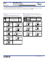
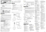
The following operating procedure describes an example of changing PV input terminal
the setting of K-type thermocouple (-199.9 to 500.0⬚C) to RTD Pt100 Thermocouple/mV/V input.............................. 12 - 13
RTD input .................................................. 11 - 12 - 13
(-199.9 to 500.0⬚C) and a measurement range of 0.0 to 200.0⬚C.
1.
Bring the operating display into view (display
appears at power on).
AL1
2
3
3. Alarm indicator
lamps
3. Alarm indicator
lamps
5.
and
AL1
4. SET/ENT
key
2. Parameter
Setpoint display
PV
2
3
4
Function
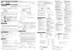
Parameter setpoint display Displays the setpoint of a parameter when it is configured.
3.
Alarm indicator lamps
2
3
4.
SET/ENT
key
5.
and
keys
AL1
2
3
AL1
7.
key once to register the setpoint.
SET/ENT
Used to switch or register a parameter. Pressing the key for more than 3 seconds allows you to switch
between the operating display and the menu for operating parameter setting display alternately.
2.
2
3
2
3
Press the
“STUP”.
4
PV
12.
OFF
1
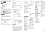
2. Setting PV Input Type (Setting First at Power-on)
K
NOTE
2
3
The indicator displays the operating display when the power is turned on. However, if PV input type has not
key to
been set, “IN” appears. In this case, first use the
display the input range code to use, then press the
key
NOTE
to register it. Then, set the maximum value (RH) and minimum
If the display is as shown on the left,
value (RL) of the PV input range (for voltage input, set the
press the
key to show the
range code for the PV input type you
maximum value (SH) and minimum value (SL) of the PV input
use. Then, register the range code
scale).
setting by pressing the
key.
The indicator is configured to the initial value of each parameter at the factory before shipment.
First check the initial values shown in 2. Lists of Parameters, in Parameters User’s Manual and change
parameter values as necessary.
J
SET/ENT
3
4
5
PV
2
T
6
4
SET/ENT
SET/ENT
•
B
7
S
8
R
Example of Temperature Input
-200°C
Example of Voltage Input
1V
1370°C
2V
4V
Set the actual
read-out
range.
0°C
800°C
Minimum value of
PV input range (RL)
Maximum value of
PV input range (RH)
PV input range
RL
Parameters to be set for temperature input
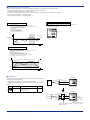
1. PV input type (IN): Set according to a sensor
2. Maximum value of PV input range (RH): Set the
maximum value of the range to be displayed.
3. Minimum value of PV input range (RL): Set the
minimum value of the range to be displayed.
(input signal)
RH
N
10
E
11
L(DIN)
12
Set the actual
read-out range.
PV input scale
13
U(DIN)
0.0m3/h
50.0m3/h
Minimum value of
PV input scale (SL)
Maximum value of
PV input scale (SH)
14
Parameters to be set for voltage input
1. PV input type (IN): Set according to an input signal
2. Maximum value of PV input range (RH): Set the maximum value of an input signal.
3. Minimum value of PV input range (RL): Set the minimum value of an input signal.
4. Position of PV input decimal point (SDP): Set the position of the decimal point for PV input display.
5. Maximum value of PV input scale (SH): Set the maximum value of the scale to be displayed.
6. Minimum value of PV input scale (SL): Set the minimum value of the scale to be displayed.
W
15
Platinel 2
16
PR20-40
17
W97Re3W75Re25
The following operating procedure describes an example of setting a K-type thermocouple (-199.9°C to 500.0°C) and a
measurement range of 0.0°C to 200.0°C.
1.
Display screen at power-on
The parameter “IN” for setting the PV input type
appears.
Displays
parameter“IN”.
PV
AL1
SET/ENT
2
3
2.
9
Thermocouple
Instrument
input range
Instrument
input range
PV input range
5V
Press the
or
key to display the required
setpoint.
The figure below shows an example of setting a
K-type thermocouple (-199.9 to 500.0°C). See the
Instrument Input Range Codes.
18
30
JPt100
31
RTD
35
Pt100
36
37
PV
Blinks during
change.
AL1
4
SET/ENT
2
3
3
Standard
signal
4
DC voltage
0.4 to 2 V
1 to 5 V
0 to 2 V
0 to 10 V
-10 to 20 mV
0 to 100 mV
40
41
50
51
55
56
4
Press the
or
key to display the required
setpoint. The figure below shows an example of
setting PV low limit alarm.
4
AL1
2
3
4
Blinks during
change.
SET/ENT
2
3
Press the
“STUP”.
key once to display the menu
The PV display in the figure above shows the error
code for input burnout (
) if PV input wiring is
not yet complete. The error code disappears when
you wire the PV input terminals correctly.
2
*
Performance in the standard condition (at 23⫾2⬚C, 55⫾10%RH, and 50/60Hz power frequency.
Note1: The accuracy is ⫾0.3⬚C of instrument range ⫾1 digit for a temperature range from 0⬚C to 100⬚C.
Note2: The accuracy is ⫾0.5⬚C of instrument range ⫾1 digit for a temperature ranges from -100⬚C to 0⬚C and 100⬚C to 200⬚C.
*
To receive a 4-20 mA DC signal, select a standard signal of 1 to 5 V DC and connect it to a 250⍀ resistor. This resistor is optional.
Model: X010-250-2 (resistor with M3.5 crimp-on terminal lugs)
Press the
key once to register the setpoint.
SET/ENT
Display menu
“STUP”.
PV
4
3
AL1
4
2
3
2
3
4
AL1
4.
Press the
“PWD”.
SET/ENT
Press the
“FUNC”.
3
4
You can take the same steps for alarm-2 type (AL2),
alarm-3 type (AL3), and alarm-4 type (AL4) that are
displayed after this.
Press the
“PWD”.
SET/ENT
key once to display the parameter
key once to display the parameter
9.
Blinks during
change.
13.
Press the
SET/ENT
Press the
key for more than 3 seconds.
This returns you to the display shown at power-on
(figure below).
SET/ENT
Displays
parameter
“PWD”.
PV
2
3
PV
4
Displays
parameter
“PWD”.
2
3
Displays
PV.
AL1
2
3
4
key once to register the setpoint.
SET/ENT
SET/ENT
2
SET/ENT
4
SET/ENT
AL1
Instrument
Measurement Accuracy
Input Range
Set the data item PV Input Type "IN" to the OFF option to leave the PV input
type undefined.
-200 to 1370⬚C
-300 to 2500⬚F
-199.9 to 999.9⬚C
0 to 2300⬚F
⫾0.1% of instrument range ⫾1 digit for temperatures
-199.9 to 500.0⬚C
equal to or higher than 0⬚C
-199.9 to 999.9⬚F
⫾0.2% of instrument range ⫾1 digit for temperatures
-199.9 to 999.9⬚C
below 0⬚C
-300 to 2300⬚F
-199.9 to 400.0⬚C
-300 to 750⬚F
0.0 to 400.0⬚C
-199.9 to 750.0⬚F
⫾0.15% of instrument range ⫾1 digit for temperatures
0 to 1800⬚C
equal to or higher than 400⬚C
32 to 3300⬚F
⫾5% of instrument range ⫾1 digit for temperatures
below 400⬚C
0 to 1700⬚C
32 to 3100⬚F
⫾0.15% of instrument range ⫾1 digit
0 to 1700⬚C
32 to 3100⬚F
⫾0.1% of instrument range ⫾1 digit
-200 to 1300⬚C
⫾0.25% of instrument range ⫾1 digit for temperatures
-300 to 2400⬚F
below 0⬚C
-199.9 to 999.9⬚C
-300 to 1800⬚F
-199.9 to 900.0⬚C
⫾0.1% of instrument range ⫾1 digit for temperatures
-300 to 1300⬚F
equal to or higher than 0⬚C
⫾0.2% of instrument range ⫾1 digit for temperatures
-199.9 to 400.0⬚C
below 0⬚C
-300 to 750⬚F
0.0 to 400.0⬚C
-199.9 to 750.0⬚F
0 to 2300⬚C
⫾0.2% of instrument range ⫾1 digit
32 to 4200⬚F
0 to 1390⬚C
⫾0.1% of instrument range ⫾1 digit
32 to 2500⬚F
⫾0.5% of instrument range ⫾1 digit for temperatures
0 to 1900⬚C
equal to or higher than 800⬚C
32 to 3400⬚F
No guarantee of accuracy for temperatures below 800⬚C
0 to 2000⬚C
⫾0.2% of instrument range ⫾1 digit
32 to 3600⬚F
-199.9 to 500.0⬚C
⫾0.1% of instrument range ⫾1 digit (Note1) (Note2)
-199.9 to 999.9⬚F
-150.0 to 150.0⬚C
⫾0.2% of instrument range ⫾1 digit (Note1)
-199.9 to 300.0⬚F
-199.9 to 850.0⬚C
-300 to 1560⬚F
⫾0.1% of instrument range ⫾1 digit (Note1) (Note2)
-199.9 to 500.0⬚C
-199.9 to 999.9⬚F
-150.0 to 150.0⬚C
⫾0.2% of instrument range ⫾1 digit (Note1)
-199.9 to 300.0⬚F
0.400 to 2.000 V
1.000 to 5.000 V
⫾0.1% of instrument range ⫾1 digit (Note)
0.000 to 2.000 V
The read-out range can be scaled between -1999 and
0.00 to 10.00 V
9999.
-10.00 to 20.00 mV
0.0 to 100.0 mV
8.
PV
SET/ENT
Select the unit from the UNIT parameter.
AL1
2
PV
4.
Displays menu
“STUP”.
AL1
■ Instrument Input Range Codes
Unspecified
3
PV
Press the
or
key to display the required
setpoint. The figure below shows an example of
setting the maximum value of PV input range to
200.0°C.
5.
PV
AL1
4
2
3
Press the
“FUNC”.
SET/ENT
SET/ENT
key once to display the menu
See “1. Setting an Alarm Setpoint” in Operations
User’s Manual when setting an alarm setpoint.
4
Displays menu
“FUNC”.
SET/ENT
SET/ENT
Instrument Input
Range Code
2
SET/ENT
PV
3
3.
Displays
parameter
“RH”.
AL1
key once to display the menu
Displays
PV.
5.
Type
7.
Displays menu
“OP.PA”.
PV
PV
Input
AL1
SET/ENT
3.
4
IMPORTANT
•
4
SET/ENT
AL1
The indicator automatically returns to the display at the time of power-on (i.e., Operating display) if no key is
operated for at least one minute.
3
Displays
parameter
“AL1”.
PV
SET/ENT
4
PV
AL1
2
Press the
key for more than 3 seconds to
call up the menu “OP.PA”.
AL1
SET/ENT
2
Press the
key once to display the parameter
“RH” (maximum value of PV input range).
SET/ENT
key for more than 3 seconds. This
returns you to the display shown at power-on (figure
below).
AL1
11.
Displays
menu “OP.PA”.
AL1
SET/ENT
The following explanation of operation for the UM351’s panel, shown in the figure, is the same as that of the UM331’s
panel.
2
SET/ENT
SET/ENT
PV
PV
Used to change numerical values. On setting displays for various parameters, you can change parameters,
setpoint. Pressing the
key decreases a numerical value, while pressing the
key causes it to
increase. You can hold down a key to gradually increase the speed of change.
7
SET/ENT
AL1
Press the
1
7
4
4
SET/ENT
If any of alarms 1 to 4 occurs, the respective alarm indicator lamp (AL1 to AL4) is lit (in orange).
SET/ENT
11. Press the
Blinks during
change.
SET/ENT
• Displays a PV value during operation.
• Displays a parameter symbol when you set a parameter.
• Displays an error code in red if the indicator fails.
2.
SET/ENT
4
SET/ENT
PV
AL1
Name of Part
Process variable (PV)
display
3
keys
4. SET/ENT key
1.
2
Press the
key for more than 3 seconds to
call up the menu “OP.PA”.
SET/ENT
Press the
or
key to display required the
setpoint. The figure below shows an example of
setting the maximum value of PV input range to
200.0°C.
keys
4
Factory-set defaults
)............PV high limit alarm
)............PV low limit alarm
)............PV high limit alarm
- 3 )......PV low limit alarm
Press the
key once to display the parameter
“AL1” (alarm-1 type).
SET/ENT
2.
If the type of input is voltage, also configure the PV
Input Decimal Point Position (SDP), Maximum value
of PV Input Scale (SH), and Minimum value of PV
Input Scale (SL) parameters that are displayed after
this.
6.
5
7
PV
4
1. Process
variable (PV)
display
UM331
2. Parameter
Setpoint
display
and
key once to register the setpoint.
Press the
key once to display the parameter
“UNIT” (PV input unit).
Displays
parameter
PV
“UNIT”.
SET/ENT
SET/ENT
5.
10.
Displays
PV.
AL1
Displays
parameter
“RH”.
PV
UM351
6.
Displays
PV.
PV
AL1
1. Names and Functions of Front Panel Parts
1. Process
variable (PV)
display
Bring the operating display into view (appears at
power-on).
SET/ENT
4
SET/ENT
1. Names and Functions of Front Panel Parts
2. Setting PV Input Type (Setting First at Power-on)
3. Changing PV Input Type
4. Changing Alarm Type
5. Setting Hysteresis in Alarm Setpoint
1.
3. Changing PV Input Type
PV
5.
Alarm-4 (terminal numbers
-
6
PV
SET/ENT
Contents
The following operating procedure describes an example of changing Alarm output terminals
alarm-1 (factory-set value: PV high limit alarm) to PV low limit alarm. Alarm-1 (terminal numbers
When you have changed alarm type, the alarm setpoint will be initial- Alarm-2 (terminal numbers
Alarm-3 (terminal numbers
ized; set the alarm setpoint again.
SET/ENT
SET/ENT
This manual describes examples of setting the types of PV input and alarm. Carrying out settings described herein allows
you to perform basic monitoring. Refer to examples of various settings to understand how to set parameters required. Refer
to “1. Parameter Map” in Parameters User’s Manual for an easy to understand explanation of setting various parameters. If you cannot remember how to carry out an operation during setting, press the
key for more than 3 seconds.
This brings you to the display (operating display) that appears at power-on.
The indicator may automatically initialize the registered operating parameter setpoints if any change is made to the
data item PV Input Type (IN), Maximum Value of PV Input Range (RH), Minimum Value of PV Input Range (RL),
PV Input Decimal Point Position (SDP), Maximum Value of PV Input Scale (SH) or Minimum Value of PV Input
Scale (SL). After a change has been made to any of these data items, be sure to verify the registered operating
parameter setpoints to ensure that they are correct. If any data item has been changed to its default, set it to a
required value.
Displays
parameter
“RL”.
PV
4. Changing Alarm Type
NOTE
key once to display the menu
14.
Press the
key once to display the parameter
“RL” (minimum value of PV input range).
Displays
menu “FUNC”.
PV
AL1
2
3
2
3
4
SET/ENT
PV
4
SET/ENT
Displays
parameter
“RL”.
AL1
2
3
5. Setting Hysteresis in Alarm Setpoint
4
The following operating procedure describes an example of setting a 5.0°C hysteresis level in the alarm setpoint.
SET/ENT
SET/ENT
1.
6.
Press the
key once to display the menu “I/O”.
15.
Press the
or
key to display the required
setpoint. The figure below shows an example of
setting the minimum value of PV input range to
0.0°C.
6.
Press the
key several times to display the
parameter “HY1” (alarm-1 hysteresis).
SET/ENT
Displays
PV.
PV
AL1
Displays
menu “I/O”.
PV
Bring the operating display into view (appears at
power-on).
2
3
4
AL1
2
3
AL1
4
2
3
Press the
key once to display the parameter
“IN” (PV input type).
SET/ENT
16.
Press the
SET/ENT
Blinks during
change.
2.
Press the
key for more than 3 seconds to
call up the menu “OP.PA”.
SET/ENT
key once to register the setpoint.
7.
Press the
setpoint.
or
Displays menu
“OP.PA”.
PV
2
3
2
3
4
AL1
4
AL1
SET/ENT
Press the
or
key to display the required
setpoint. The figure below shows an example of
changing to RTD Pt100 (-199.9 to 500.0°C).
Blinks during
change.
AL1
2
3
17.
2
3
Press the
“STUP”.
Blinks during
change.
SET/ENT
key once to display the menu
SET/ENT
8.
Press the
SET/ENT
AL1
Displays
PV.
PV
AL1
2
3
Display menu
“STUP”.
PV
key once to register the setpoint.
2
3
PV
4
AL1
SET/ENT
2
3
4
SET/ENT
You can take the same steps for alarm-2 hysteresis
(HY2), alarm-3 hysteresis (HY3), and alarm-4
hysteresis (HY4) that are displayed after this.
4
SET/ENT
4.
SET/ENT
4
4
Press the
key for more than 3 seconds.
This returns you to the display shown at power-on
(figure below).
4
SET/ENT
Press the
3
SET/ENT
PV
9.
2
PV
3.
8.
key to display the required
PV
SET/ENT
AL1
4
SET/ENT
AL1
Displays
parameter “IN”.
PV
3
4
SET/ENT
SET/ENT
7.
2
PV
SET/ENT
AL1
Displays
parameter
“HY1”.
PV
key once to register the setpoint.
PV
* If the type of input is voltage, also configure the
PV Input Decimal Point Position (SDP), Maximum
value of PV Input Scale (SH), and Minimum value
of PV Input Scale (SL) parameters that are
displayed after patameter RL.
Press the
“PWD”.
SET/ENT
key once to display the parameter
Displays
parameter
“PWD”.
PV
AL1
AL1
2
3
2
3
9.
Press the
key for more than 3 seconds.
This returns you to the display shown at power-on
(figure below).
SET/ENT
PV
4
Displays
PV.
AL1
2
3
4
4
SET/ENT
SET/ENT
SET/ENT
5.
Press the
“FUNC”.
SET/ENT
key once to display the menu
Displays menu
“FUNC”.
PV
AL1
2
3
4
SET/ENT
IM 05F01D12-02E (1)