1
2
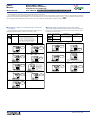
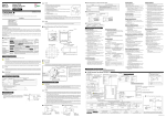
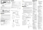
■ Functions of Active Color PV Display
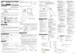
This part describes the functions of “Active Color PV Display.” PV display color is changed by the following four actions.
PV display is selectable from red-to-green or green-to-red changing action, or fixed color.
Link to alarm 1 mode (when PCMD = 2, 3) (Setting example-1)
Link to alarm 1 and 2 mode (when PCMD = 4, 5) is the same. When either of the alarms occurs, the display color is changed.
PV limit mode (when PCMD = 6, 7) (Setting example-2)
Fixed color mode (when PCMD = 0, 1) (Setting example-3)
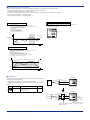
Setting Example-3 : Fixed in Red or Green
Setting Example-1 : Link to Alarm
Set the PV display color or Fixed in green mode, Setting of Fixed to red mode is also possible.
Setting parameter
PCMD (PV color mode parameter) = 0
Works linked to alarm 1.
Set “PV high limit alarm” for alarm 1 type, and “80°C” for alarm 1 setpoint.
If PCMD (PV color mode parameter) = 2, PV display color is changed from green to red
when PV input value exceeds alarm 1 setpoint.
The red-to-green changing action is selectable.
Setting parameters
PCMD (PV color mode parameter) = 2
AL1 (Alarm 1 type parameter) = 1
A1 (Alarm 1 setpoint parameter) = 80°C
HY1 (Alarm 1 hysteresis parameter) = 5°C
PV : green
°C
Alarm 1 hysteresis
Alarm 1 setpoint
A1=80°C
75°C
PV
PV : red
PV : green
Time
PV : green
Setting Example-2 : Link to PV
Set high limit “70°C” for PCCH, and low limit “20°C” for PCCL.
PV display color is changed from green to red when PV input value is out of the range.
The red-to-green changing action is selectable.
Setting parameters
PCMD (PV color mode parameter) = 6
PCCH (High limit for PV color change parameter) = 70°C
PCCL (Low limit for PV color change parameter) = 20°C
Hysteresis fixed to 0.25% is inserted where PV display color is changed.
In the example blow, where changed from red to green.
°C
High limit for PV color change parameter “PCCH” = 70°C
PV : red
70°C
PV : green
Low limit for PV color change parameter “PCCL” = 20°C
20°C
PV : red
PV
Time
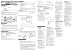
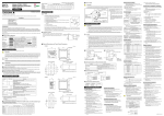
■ External RJC
UM351/UM331
External RJC is not a compensation function built in a indicator but a compensation
function working outside the indicator.
External RJC is used when input is thermocouple, and RJC=OFF.
Terminal block
Compensating wire
Thermocouple
Furnace
Using External RJC makes the accuracy of RJC higher and shortens the compensating wire.
Parameter
Name of Parameter
Setting Range
Initial Value
Symbol
External RJC setpoint
(ERJC)
-50.0 to 50.0°C, -58.0 to 122.0°F
For thermocouple input, temperature compensation value
outside the indicator can be set.
Available only when RJC=OFF.
0.0°C
32.0°F
UM351/UM331
Terminal block
Normal wiring
Thermocouple
Furnace
Example :
Setting parameters
RJC = OFF
ERJC = 25.0°C
Compensating wire
Installed in an area where
ambient temperature is
fixed.
All Rights Reserved. Copyright © 2003, Yokogawa Electric Corporation
Set the temperature in the
area using ERJC parameter.
IM 05F01D12-04E