1
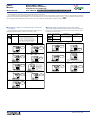
2. Lists of Parameters
* Parameters relating to PV should all be set in real numbers.
For example, use temperature values to define alarm setpoints for
temperature input.
Name of Parameter
Alarm 1-setpoint
Setting Range and Description
Initial Value
PV alarm: -100.0 to 100.0% of PV input range
User setting
PV high limit
alarm:
100.0% of
PV input range
PV low limit
alarm:
0.0% of
PV input range
(A1)
Alarm 2-setpoint
(A2)
Alarm 3-setpoint
(A3)
Parameter
Symbol
Name of Parameter
Setting Range and Description
(IN)
PV input type (PV INPUT
terminals)
11 - 12 - 13 terminals
PV input unit
OFF, 1 to 18, 30, 31, 35 to 37, 40, 41, 50, 51, 55, 56
See Instrument Input Range Codes in Initial
Settings User’s Manual .
°C: degree Celsius
°F: Fahrenheit
Max. value of PV input
range
(RH)
Alarm 4-setpoint
Min. value of PV input
range
PV peak value
Displays the maximum value of PV input during operation.
This parameter is not to be set.
PV bottom value
Displays the minimum value of PV input during operation.
This parameter is not to be set.
(RL)
(PEAK)
(SDP)
(BOTM)
PV input filter
OFF, 1 to 120 second
Used when the PV input fluctuates.
OFF
PV input bias
-100.0% to 100.0% of PV input range span
Used to correct the PV input value.
0.0% of PV
input range
span
High limit for
PV color change
When PCMD (PV color mode parameter) = 6 or 7 :
-100.0 to 100.0 % of PV input range
(FL)
(BS)
(SH)
When PCMD = 6 or 7 :
PCCH = 100.0%,
PCCL = 0.0 %
(PCCH)
(SL)
Low limit for
PV color change
(BSL)
(PCCL)
■ Setup Parameters
(RJC)
● Alarm/Communication-related Parameters
Name of Parameter
Initial Value
OFF
Alarm type code
User Setting
Alarm type
“Open/close” shows status of relay contact,
and “lit” and “unlit” shows status of lamp
°C
PV input decimal point
position (displayed
at voltage input)
Set the PV input range, however RL < RH
-Temperature input
Set the range of temperature that is actually indicated.
- Voltage input
Set the range of a voltage signal that is applied.
The scale across which the voltage signal is actually
indicated should be set using the parameters
Maximum Value of PV Input Scale (SH) and Minimum
Value of PV Input Scale (SL).
0 to 3
Set the position of the decimal point of voltagemode PV input.
0: No decimal place
1: One decimal place
2, 3: Two, three decimal places
-1999 to 9999, however SL < SH
Set the read-out scale of voltage-mode PV input.
Max. value of PV input
scale
(displayed at voltage input)
Min. value of PV input
scale
(displayed at voltage input)
Selection of PV input
OFF
burnout action
1: Up scale
2: Down scale
OFF, ON
Presence/absence of
PV input reference
junction compensation
External RJC setpoint
-50.0 to 50.0 ⬚C
-58.0 to 122.0 ⬚F
Contact
closes
if alarm
occurs
No alarm
“Open/close” shows status of relay contact,
and “lit” and “unlit” shows status of lamp
PV high limit
Open (unlit)
De-energized
on PV high limit
Closed (lit)
PV
PV low limit
Hysteresis
1
Alarm setpoint
Closed (lit)
De-energized
on PV low limit
Initial Value
User setting
(PCMD)
Alarm-1 type
(AL1)
Alarm-2 type
(AL2)
Alarm-3 type
(AL3)
Alarm-4 type
(AL4)
0: Fixed in green
1: Fixed in red
2: Link to alarm 1 (Alarm OFF:green, Alarm ON:red)
3: Link to alarm 1 (Alarm OFF:red, Alarm ON:green)
4: Link to alarm 1 and 2 (Alarm OFF:green, Alarm ON:red)
5: Link to alarm 1 and 2 (Alarm ON:red, Alarm OFF:green)
6: PV limit (Within PV range:green, Out of PV range:red)
7: PV limit (Within PV range:red, Out of PV range:green)
1
OFF
1: PV high limit (energized, no stand-by action)
2: PV low limit (energized, no stand-by action)
9: PV high limit (de-energized, no stand-by action) 2
10: PV low limit (de-energized, no stand-by action)
11: PV high limit (energized, stand-by action)
12: PV low limit (energized, stand-by action)
1
19: PV high limit (de-energized, stand-by action)
20: PV low limit (de-energized, stand-by action)
21: Fault diagnosis output
2
Turns on in case of input burnout, A/D
converter failure, or reference junction
compensation (RJC) failure.
22: FAIL output
Turns off in case of program failure, ROM
failure, RAM failure, or power failure. This
output is on during normal operation. If it
turns off, the retransmission output is set to
0%, the alarm output is set to OFF, and the
indicator stops.
1
(RTH)
(RTL)
Fault diagnosis output (Note1)
100.0
⬚C
ON
RET=1: RTL + 1 digit to 100.0% of PV
input range
100.0% of
PV input range
RET=1: 0.0% of PV input range to
RTH - 1 digit
0.0% of
PV input range
OFF: The external contact input is disabled.
1: Resets the values of the PEAK and BOTM
operating parameters to an off-to-on transition
of the DI1 input.
OFF, 201 to 1015
1
Abnormal
The alarm
output turns on.
It is effective in the following cases where;
- the power is turned on
- the alarm type is changed
SELECT display-2
registration
(C.S2)
SELECT display-3
registration
(C.S3)
See “List of Alarm Types” on the right side of this
manual for details on how these Alarm Type
parameters behave.
Alarm-1 hysteresis
0.0 to 100.0% of PV input range span
Alarm-2 hysteresis
Hysteresis can be set in the alarm setpoint.
Setting hysteresis prevents relays from
chattering.
(HY1)
(HY2)
Alarm-3 hysteresis
0.5% of PV
input range span
Password setting
Hysteresis setting for PV high limit alarm
Output
(HY3)
Alarm-4 hysteresis
Point of on-off action
(Alarm setpoint)
(PWD)
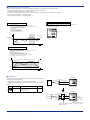
● Behavior of the PV High-limit Alarm Parameter (Alarm Type Code: 1)
PV value
Alarm hysteresis
OFF
For example, registering “231” for C.S1 allows you to
change alarm-1 setpoint in operating display.
Numbers for registering alarm SP parameter for
operating display:
Alarm-1 setpoint: 231 Alarm-2 setpoint: 232
Alarm-3 setpoint: 233 Alarm-4 setpoint: 234
Off
Alarm
contact output
On
Off
■ Useful Operating Display (SELECT Display)
(C.S4)
(LOCK)
Time
Power-on
Alarm
setpoint
SELECT display-4
registration
Key lock
Low limit of
alarm setpoint
The alarm output does not
turn on in this region even
if the PV value is below the
low limit of the alarm setpoint.
0.0 ⬚C
32.0 ⬚F
Max. value of
retransmission output
scale
Min. value of
retransmission output
scale
DI function selection
22
Normal
Treated
as normal
1
1
(C.S1)
20
Note1: Fault diagnosis output
Turns on in case of input burnout, A/D converter failure, or reference junction compensation (RJC) failure.
Note2: FAIL output
Turns off in case of program failure, ROM failure, RAM failure, or power failure. This output is on during normal operation. If it turns
off, the retransmission output is set to 0%, the alarm output is set to OFF, and the indicator stops.
Stand-by Action
1: PV
4: Loop power supply for sensor (15 V)
SELECT display-1
registration
PV
FAIL output (Note2)
21
0.0
Retransmission output
type
(DIS)
10
1
(RET)
PV color mode
19
Closed
(unlit)
Alarm setpoint
(ERJC)
Setting Range and Description
Alarm setpoint
Open (lit)
12
PV
Contact
opens
if alarm
occurs
9
Hysteresis
2
Contact
closes
if alarm
occurs
Open (lit)
PV
Open (unlit)
Alarm setpoint
Closed
(unlit)
11
Hysteresis
Min. value of
instrument
input range
Alarm type
Contact
opens
if alarm
occurs
OFF
Hysteresis
Max. value of
instrument
input range
Alarm type code
Alarm action
Alarm action
(UNIT)
(A4)
Parameter
Symbol
The table below shows the alarm types and alarm actions.
In the table, codes 1, 2, 9, and 10 are not provided with stand-by actions, while codes 11, 12, 19, and 20 are provided with
stand-by actions.
● Input-/Output-related Parameters
■ Operating Parameters
Parameter
Symbol
■ List of Alarm Types
* The “User Setting” column in the table below is provided for the customer to record setpoints.
OFF: No key lock
OFF
1: Change to any parameter prohibited
Prohibits any operating parameter or setup
parameter from being changed. The setpoint
of the LOCK parameter itself can be changed,
however.
2: Change to and display of operating parameters
prohibited
Turns off the display for setting operating
parameters, thus prohibiting any change to
the parameter settings.
(Press the SET/ENT key for more than
3 seconds to show the password check
display.)
0: Password not set
1 to 9999
Registering frequently changed parameters in the SELECT display after ordinary operating displays will allow you to
change settings easily. A maximum of four displays can be registered.
Useful
operating display
(SELECT display)
Ordinary operating
displays (example)
PV
Setting method:
Set the parameter numbers (D register numbers) you wish to register for
setup parameters C.S1 to C.S4.
For any registration number other than those above, see User’s Manual (Reference) (CD-ROM version).
PV
0
AL1
2
3
4
AL1
SET/ENT
2
3
4
key
SET/ENT
SET/ENT
On
PV display
(HY4)
Alarm-1 setting
display (example)
Hysteresis
Off
SET/ENT
key
PV value
Alarm-1 delay timer
(DY1)
An alarm is output when the delay timer expires
after the alarm setpoint is reached.
0.00 to 99.59 (min, sec.) (enabled when alarm1 type “AL1” is 1, 2, 9, 10, 11, 12, 19, and 20)
0.00
● Numbers for Registration with SELECT Display
PV
Operating Parameter
Alarm setpoint
Hysteresis
Delay timer
Alarm output
Delay timer
on
off
Time
Alarm-2 delay timer
0.00 to 99.59 (min, sec.) (enabled when alarm2 type “AL2” is 1, 2, 9, 10, 11, 12, 19, and 20)
Alarm-3 delay timer
0.00 to 99.59 (min, sec.) (enabled when alarm3 type “AL3” is 1, 2, 9, 10, 11, 12, 19, and 20)
Alarm-4 delay timer
0.00 to 99.59 (min, sec.) (enabled when alarm4 type “AL4” is 1, 2, 9, 10, 11, 12, 19, and 20)
Protocol selection
0: PC link communication
1: PC link communication (with sum check)
2: Ladder communication
7: MODBUS (ASCII)
8: MODBUS (RTU)
0: 600, 1: 1200, 2: 2400, 3: 4800, 4: 9600 (bps)
Registration Number
Setup Parameter
Registration Number
Alarm-1 setpoint (A1)
231
Alarm-1 hysteresis
919
Alarm-2 setpoint (A2)
232
Alarm-2 hysteresis
920
Alarm-3 setpoint (A3)
233
Alarm-3 hysteresis
921
Alarm-4 setpoint (A4)
234
Alarm-4 hysteresis
922
Bias (BS)
243
Filter (FL)
244
(DY2)
(DY3)
(DY4)
(P.SL)
Baud rate
0
4
(BPS)
Parity
(PRI)
Stop bit
0: None
1: Even
2: Odd
1, 2
1
1
(STP)
Data length
(DLN)
Address
(ADR)
Minimum response
time
7, 8
Fixed at 7, when the P.SL parameter is set to
MODBUS (ASCII).
Fixed at 8, when the P.SL parameter is set to
MODBUS (RTU) or Ladder Communication.
1 to 99
However, the maximum number of stations
connectable is 31.
0 to 10 (⫻ 10 ms)
8
1
0
(RP.T)
If this parameter symbol appears, press the SET/ENT key to return to the FUNC menu.
(TEST)
Caution: Do not change the setpoint of the TEST parameter, otherwise the indicator will be disabled.
IM 05F01D12-03E (2)